Article

Assessment of Direct Injected Liquefied Petroleum Gas-Diesel Blends for Ultra-Low Soot Combustion Engine Application

1
CNR–Istituto Motori, Viale Marconi, 4, 80125 Naples, Italy
2
Department of Chemical, Materials and Production Engineering, University of Naples Federico II, via Claudio, 21, 80125 Naples, Italy
*
Author to whom correspondence should be addressed.
Appl. Sci. 2020, 10(14), 4949; https://doi.org/10.3390/app10144949
Submission received: 19 June 2020 / Revised: 13 July 2020 / Accepted: 15 July 2020 / Published: 18 July 2020

Abstract

:
Technological and economic concerns correlated to fulfilling future emissions and CO2 standards require great research efforts to define an alternative solution for low emissions and highly efficient propulsion systems. Alternative fuel formulation could contribute to this aim. Liquefied petroleum gas (LPG) with lower carbon content than other fossil fuels and which is easily vaporized at ambient conditions has the advantage of lowering CO2 emissions and optimizing the combustion process. Liquefied petroleum gas characteristics and availability makes the fuel a promising alternative for internal combustion engines. The possible combination of using it in high-efficiency compression ignition engines makes it worth analyzing the innovative method of using LPG as a blend component in diesel. Few relevant studies are detectable in literature in this regard. In this study, two blends containing diesel and LPG, in volume ratios 20/80 and 35/65, respectively, were formulated and utilized. Their effects on combustion and emissions performance were assessed by performing proper experimental tests on a modern light-duty single-cylinder engine test rig. Reference operating points at conventional engine calibration settings were examined. A specific exhaust gas recirculation (EGR) parametrization was performed evaluating the LPG blends’ potential in reducing the smoke emissions at standard engine-out NOx levels. The results confirm excellent NOx-smoke trade-off improvements with smoke reductions up to 95% at similar NOx and efficiency. Unburnt emissions slightly increase, and to acceptable levels. Improvements, in terms of indicated specific fuel consumption (ISFC), are detected in the range of 1–3%, as well as the CO2 decrease proportionally to the mixing ratio.

Highlights:
  • Innovative solution to fuel a compression ignition (CI) diesel engine with low-sooting fuels;
  • Alternative fuels for diesel engines: new frontiers to exploit high-efficiency CI engines;
  • Liquefied petroleum gas (LPG)–diesel blends effective approach for ultra-low soot-NOx engine application;
  • Stable and efficient combustion for LPG–diesel blends in CI engines;
  • LPG–diesel blend storage modification for CI engine application.

1. Introduction

The concentration of CO2 is increasing due to fossil fuel combustion, and one of the most significant contributors to worldwide CO2 emissions is the transport sector. Transportation is responsible for almost 30% of the total CO2 emissions in Europe, of which 72% are attributed to road transportation. As part of the effort to reduce CO2 emissions, the 2050 target is to reach 60% less compared to the 1990 level [1]. Within this context, the use of alternatives (e.g., liquefied petroleum gas (LPG), natural gas, and alcohols, etc.) to liquid fossil fuels, combined with new combustion concepts [2] and engine technology paths (turbocharging, right-sizing, electrification, etc.) is a feasible way to achieve better efficiency and meet emissions targets. Advanced combustion approaches in a compression ignition (CI) engine have the potential of higher efficiency and face the high NOx-soot emission dilemma, as one of the main drawbacks for diesel engines [3]. However, the use of alternative fuels will further limit the soot production during the combustion process by replacing, for example, a portion of the diesel with a less-sooty fuel like LPG [4,5].
LPG, as a by-product of crude oil refining processes, is composed mainly of propane (80%) and butane (20%). In particular, the propane is like diesel fuel. It can be liquefied under 760–1030 kPa pressure at ambient temperature and mixed with diesel in any proportion. Theoretically, the high-octane number (correspondent to low cetane number) makes the fuel suitable for operating in high compression ratio CI engines. LPG fuel, in both phases, can be employed in a diesel engine. In dual-fuel combustion mode, the LPG is taken into the cylinder through a port fuel injector (PFI) into the intake manifold, and the air-LPG mixture induced into a combustion chamber. A small diesel quantity is injected for the ignition of the LPG-air mixture [6]. The LPG used in a diesel engine has been widely studied and ensures better engine performance, low particles, and smoke emissions according to the results in the literature [7].
The LPG-diesel is injected into the combustion chamber at high pressure, therefore rapidly passing to the gas phase due to the low boiling point. The quick LPG evaporation improves the atomization of the blend spray [8]. Increasing the LPG percentage will reduce the cetane number (CN), as well as the lower heating value (LHV) and the latent heat of evaporation, which causes an increase in the ignition delay [4]. However, the LPG high percentage could bring combustion noise and engine knock [9,10]. Cao et al. [9] investigated the use of LPG and diesel mixture in CI engines. The test campaign was performed using blends at various LPG ratios (10% and 30%). No variations were observed in terms of engine performance for the used fuels at a constant speed. The best results for the emissions have been obtained using the 30% LPG ratio with a penalty of hydrocarbons (HC) emission. Ma et al. [10] studied the effect of the diesel-propane blend in the CI engine. At different propane percentages, heat release rate, combustion phase, peak firing pressure, and NOx emissions increased at the same engine speed-load, while the combustion duration, smoke, CO, and HC emissions were reduced.
The experimental activity was dedicated to the evaluation of the LPG-diesel potential in terms of both emissions and thermal efficiency compared to the conventional diesel one. Two diesel-LPGs at different mass ratios, 20% and 35% in mass named “DLPG20” and “DLPG35”, respectively, were tested. Also, a hydraulic characterization was carried out in order to provide useful information for evaluating the LPG influence on injector performance. The hydraulic characterization tests were performed at the same injection strategies to have a direct comparison with the test on the single-cylinder engine (SCE). The activity was part of a research theme that aims to use the LPG–diesel mixture in a CI engine through the adaptation of the conventional injection system with few modifications. The main purpose of this study is to assess the applicability of the proposed concept and the potential in the real operating conditions. The present study, with its methodology and analysis, aims to cover the information and the scientific gap with what is present in the literature.

2. Materials and Methods

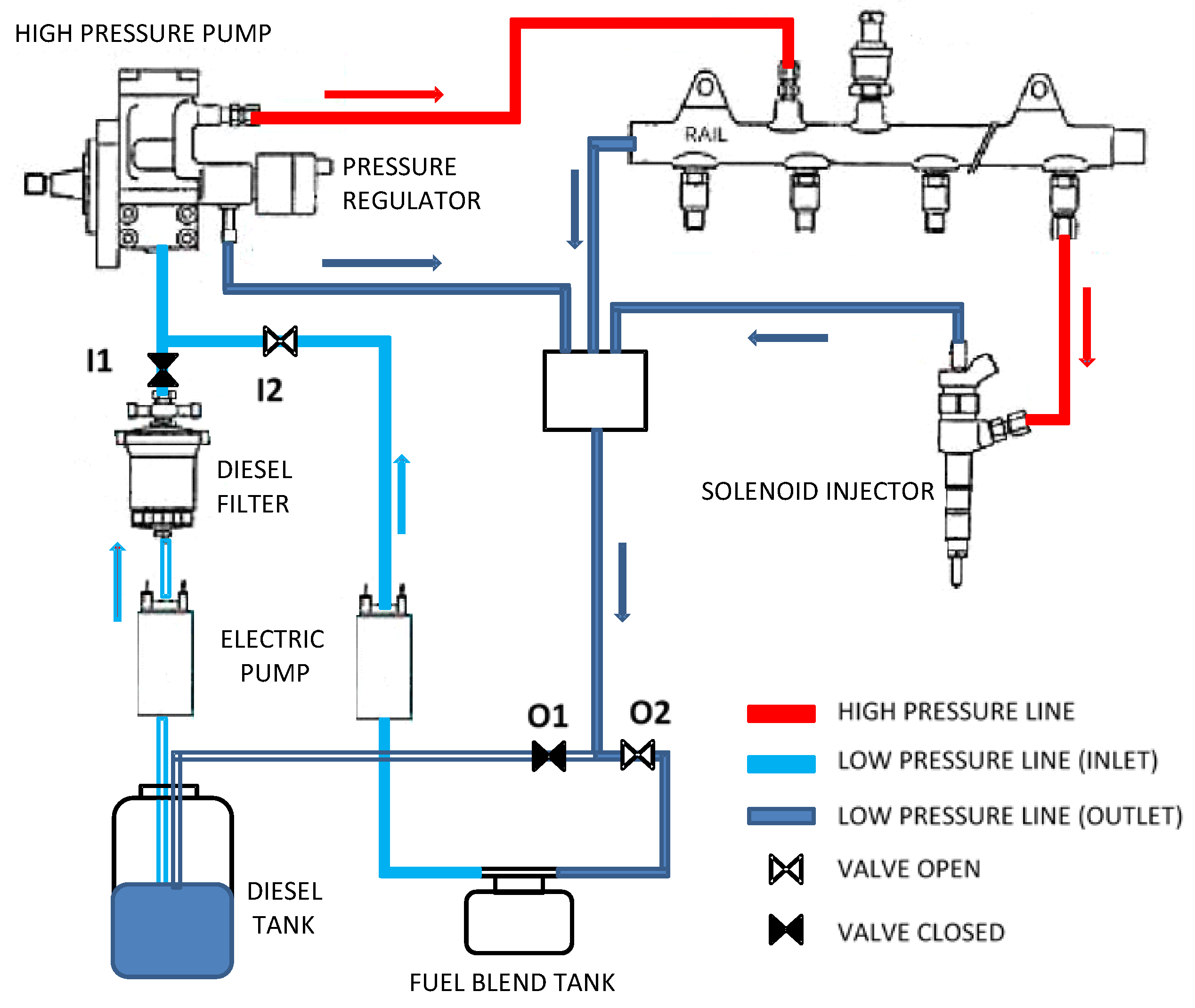
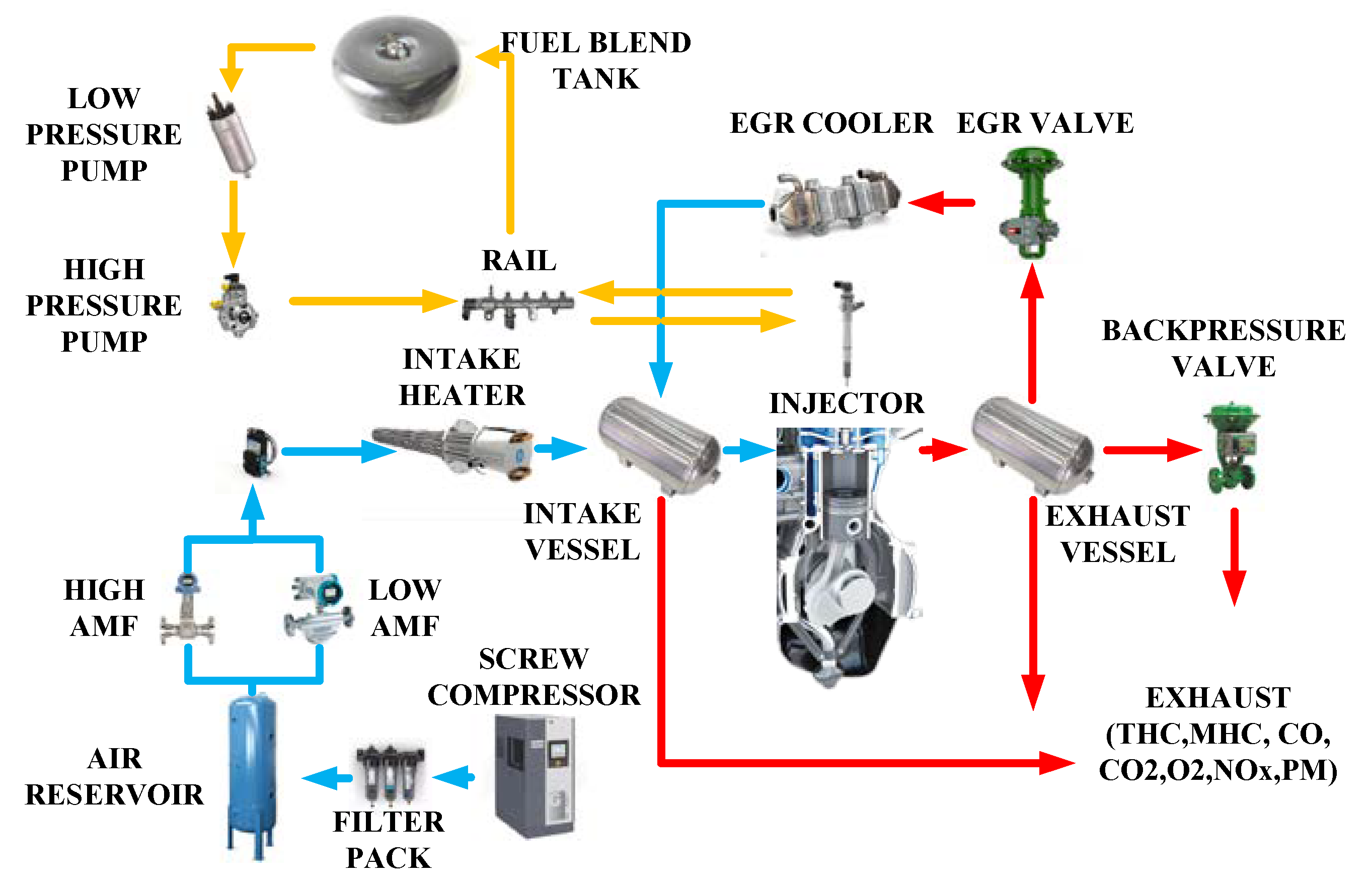
2.1. Experimental Setup

The experimental test rig employed a prototype SCE integrating the main combustion system components of a modern CI ignition engine. The fuel system was refurbished to permit the use of LPG/diesel blends. Some critical aspects were evidenced during the experimental test campaign, such as the blend temperature increase during the engine run and the need to modify the fuel system to ensure the liquid phase on supply and return fuel lines. It is worth underlining that the petroleum gas was liquid, which is LPG, at a pressure above the 5 bar pressure at ambient temperature. To this aim, the injection return line was modified to ensure sealing at higher pressures. For this reason, LPG could not be directly mixed in the diesel fuel tank, and for the storage of the mixture, a proper pressurized LPG-fuel tank was used. The tank made of anti-corrosion metal material must guarantee the absence of fluid leaks, and must also withstand pressures of 20 bar, and above the nominal working pressure of 8 bar, for safety reasons. In the LPG configuration, as illustrated in Figure 1, the fuel filter was not installed to prevent the fuel phase separation (liquid to gaseous) due to the concentrated pressure losses. The fuel tanks and system described needed to be filled every time before starting the test campaign. However, to have a more flexible system for real engine applications, further developments of the storage and fuel lines are under consideration. The injection system, fuelled by diesel-LPG, a closed pressure circuit (8 bar), was realized to avoid vaporization by reducing the risk of cavitation at the inlet of the high-pressure pump [4]. The fuelling system was modified in a way it could exploit the original diesel injection system composed of a conventional common rail solenoid injector with a 7-hole nozzle characterized by a 0.14 mm diameter and a cone angle of 148 degrees.
The other engine components were properly designed, manufactured, and assembled at the CNR-Istituto Motori laboratories. A system capable of monitoring and controlling the engine control parameters, pressure, temperature signals, and pollutant emissions was developed on Labview. Combustion metrics (indicating) were measured and calculated on the base of a piezo quartz pressure sensor. The average cycle was estimated by 128 consecutive cycles at the sampling rate of 0.1 degree and used for detailed thermodynamic analysis. For a comprehensive thermodynamic characterization of the engine system, the entire test rig was equipped with pressure and temperature sensors. An exhaust gas-analyzer model AVL CEB II and AVL315s were used to measure gaseous and smoke emission composition at the exhaust, respectively. A detailed scheme of the test cell layout is depicted in Figure 2.
Fuel consumption evaluation, as the LPG-diesel blend system was designed, was not possible through a conventional gravimetric balance. Therefore, to determine the fuel consumption, an indirect estimate of fuel consumption was obtained by equating the carbon mass in the exhaust to the carbon concentration of the fuel, estimated from the exhaust emissions (CO2, CO, and HC).
The detailed procedure for the indirect calculation of fuel consumption is given in Appendix A. The applied method was preliminarily validated by comparing the fuel consumption of diesel, using the conventional open-circuit fuelling system, measured by the gravimetric balance and the calculation methods. The maximum detected error was around 3%. The employed nozzle characteristics are listed in Table 1.
It is well known that the combustion process and its associated emissions are significantly affected by the injection process, as well as the fuel properties. To better identify their effects on the combustion process, a specific injector test campaign hydraulic characterization was associated with the engine tests. The injection flow was affected, among other factors, mainly by the viscosity, density, and especially the boiling point. Therefore, the injector, fuelled with different fuels, was hydraulically characterized by a fuel injection rate meter working on the Bosch tube principle [11]. The injected fuel amount was obtained by the relative pressure signal [12] and was proportional to the injection rate through the pipes’ geometry and the fuel chemical-physical properties [11]. The results were averaged over more than 100 strokes, and the standard deviation was around 2%. The diesel quantity was compared with those obtained at the discharge pipe by a precision balance while for the LPG blends, being the outlet at atmospheric backpressure, and in such conditions, the LPG was in the gaseous state, and it was not possible to compare the results.

2.2. Test Methodology and Fuel Characteristics

A set of four-engine partial load points were chosen for the setup of the experimental campaign. They were inside the Worldwide Harmonized Light Vehicles Test Procedure (WLTP) operating area, and therefore usable as an indicator for efficiency and emission performance at partial load conditions. In this regard, they were performed, applying a reference engine parameter calibration (rail pressure, intake pressure, swirl, exhaust gas recirculation (EGR), etc.) derived from a real four-cylinder engine with the same engine architecture of the SCE. The key-points are schematically reported in Figure 3 and named synthetically as engine speed per brake mean effective pressure (BMEP), e.g., 1500 × 5 indicates 1500 rpm per 5 bar BMEP. For this work, four operating points were selected, two speeds (1500 and 2000 rpm), and two loads (2 and 5 bar of BMEP) points at constant engine out NOx level. To better explore and analyze the LPG blends potential, a conventional pattern characterized by a pilot-main injection was employed. The start of injection (SOI) of the pulses and the main energizing time (ET) were adjusted to achieve the reference diesel combustion barycentre (MBF50) and load values; also, the EGR rate was controlled to achieve the constant NOx target. All the additional injection parameters (ET pilot, dwell time, rail pressure, etc.) were maintained constant and equal to the reference values. As regards the hydraulic characterization, both pilot and main injection, the mass flow profiles for different fuels were performed under the same injection conditions tested on the SCE.
In this regard, the following fuels were considered in this study:
  • Reference EN590 European commercial diesel;
  • Blend of 20%wt of LPG in diesel (DLPG20);
  • Blend of 35%wt of LPG in diesel (DLPG35).
Table 2 reports the main chemical and physical characteristics of the reference diesel and LPG, and the roughly estimated ones, obtained by linear interpolation.
For the sake of completeness, the EGR sweep results are presented in terms of the NOx-particulate matter (PM) trade-offs. The analysis was very effective and is a general approach employed for evaluating the potential of fuel formulations, technologies, etc. fuel–engine interaction performance and, in particular, for the critical engine control conditions in terms of NOx and PM.

3. Results and Discussion

This section is divided into three parts. The first part analyses the effects of the factors on the global injector response to different fuels through a hydraulic characterization. Next, the tested points comparison is presented in terms of performance, combustion noise, and emissions. Finally, a trade-off emission analysis carried out through the EGR sweep is shown for all the operating points using different blends comparing to a diesel one.

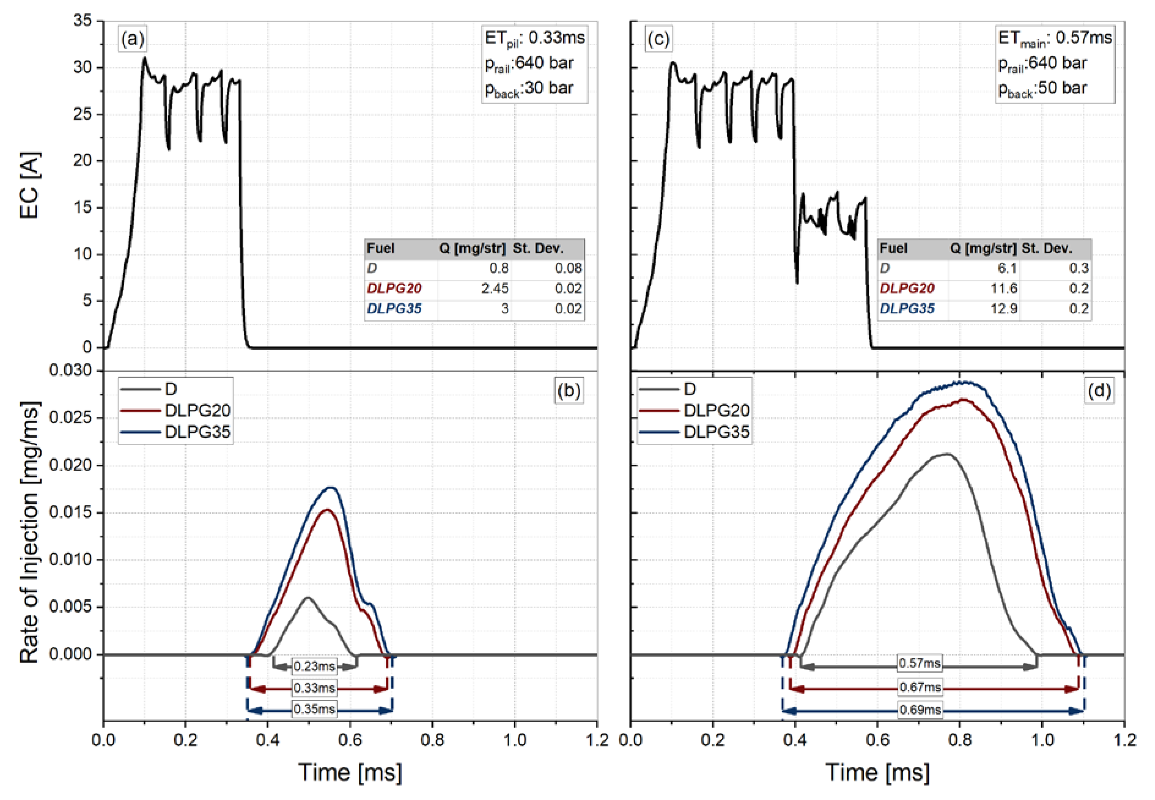
3.1. Hydraulic Characterization

In this section, the main results obtained in the study are analyzed. The focus is pointed to the description of the hydraulic results, showing the injection rate shape characteristics of each tested fuels. Figure 4 shows the rate of injection (ROI) traces for all the fuels used in the test campaign, respectively. The injection rate, therefore, the fuel injection quantity, as discussed above, is obtained by the pressure signal, the pipes’ geometric characteristics, and the fuel chemical-physical characteristics, reported in Table 2 [4]. ROI profiles with two different energizing times, which correspond to a pilot and main injections for the 1500 × 2 test case at the injection pressures of 640 bar, are shown in Figure 4 for all tested fuels. Both tests were carried out in the engine-like backpressure conditions (pback), at 30, and 50 bar for the pilot and main injection, respectively.
Regarding the injector performance, there is a hydraulic delay defined as the time between the electric command and the fuel injection; more details are available in the literature [13]. The different viscosity, as well as the compressibility of the blends (due to the presence of LPG) in comparison to diesel fuel, justifies the differences in the dynamic and injection timing. The hydraulic delay is reduced proportionally to the LPG percentage, in the range 0.35–0.4 ms, while for the conventional diesel is higher by around 15%. Similar considerations also for the closing phase, with greater durations in the range 0.1–0.12 ms for the blends, keeping constant the energizing time (ET). Therefore, different amounts of delivered fuel have been registered at the same ET; the values are inserted in Figure 4c,d. The trends observed for this operating point can be extended to the other points tested and are not reported here for brevity. In general, the hydraulic characterization has confirmed the blends do not alter the injector performance except for the different opening and closing delays of the mixture, which can be solved through an appropriate calibration of the engine map.

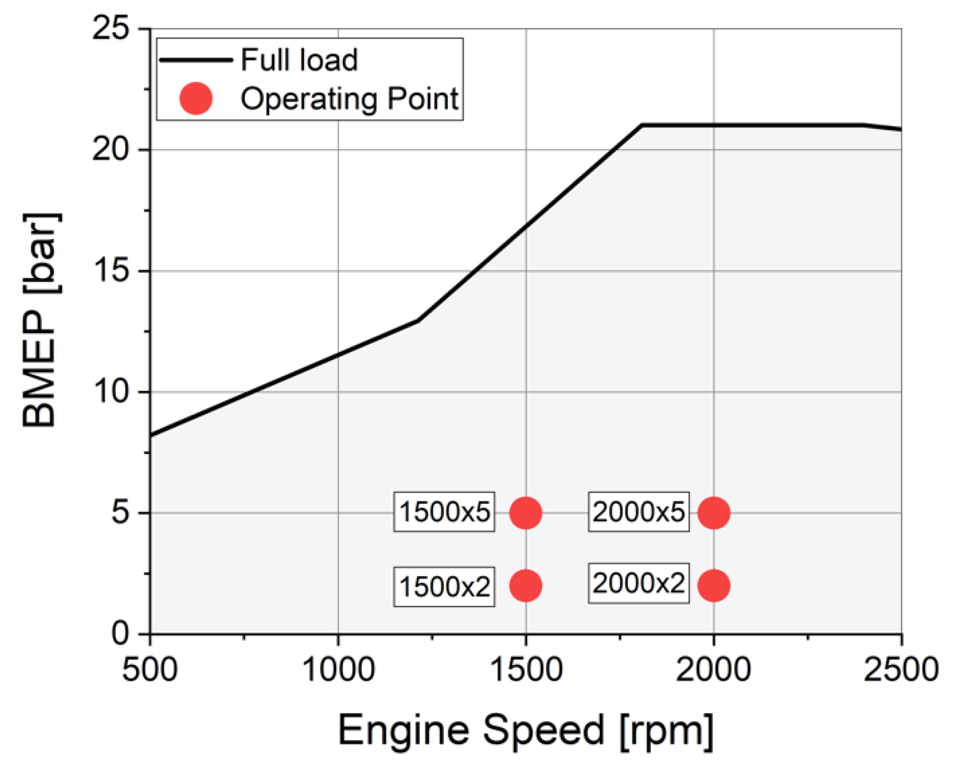
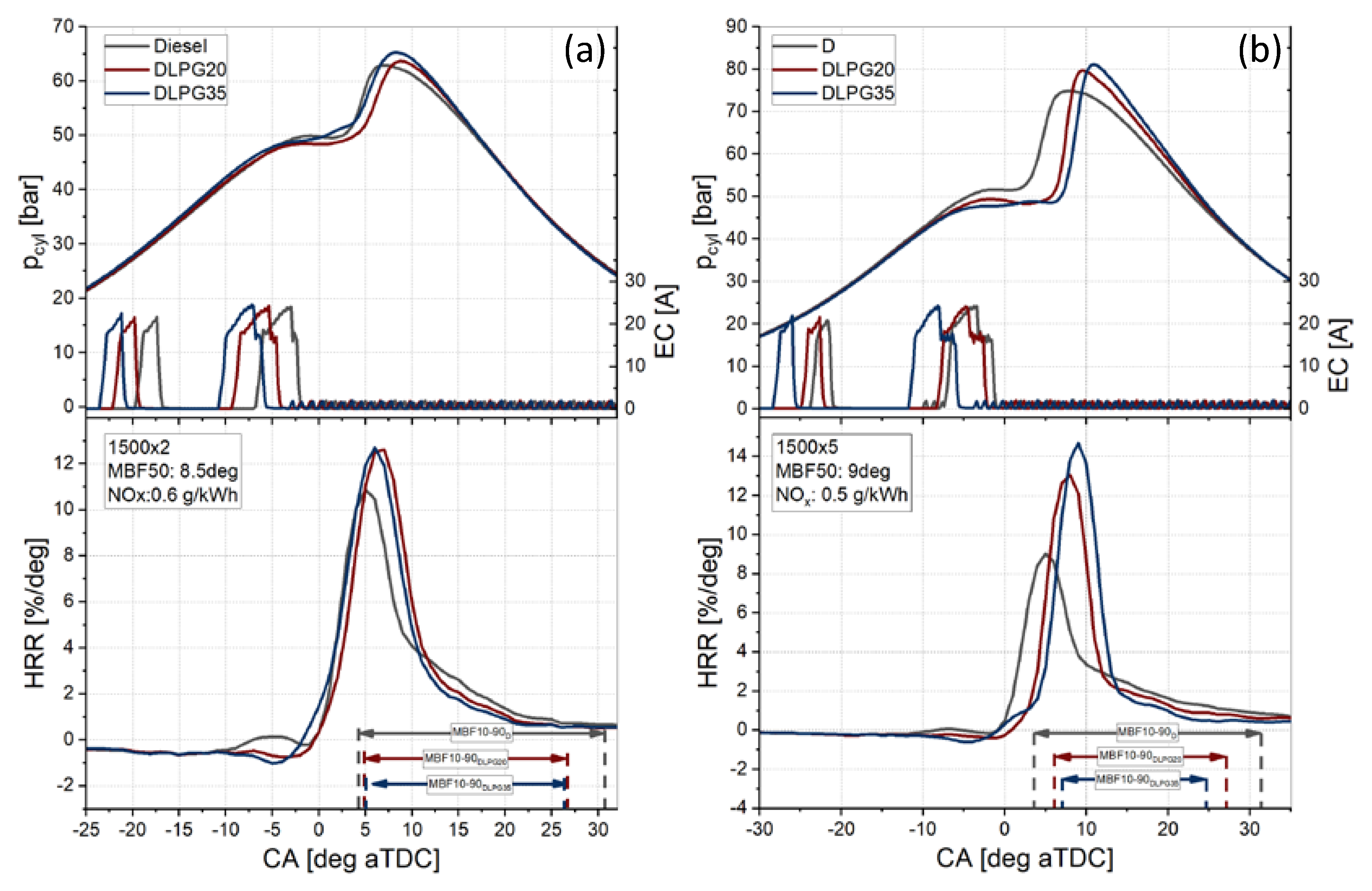
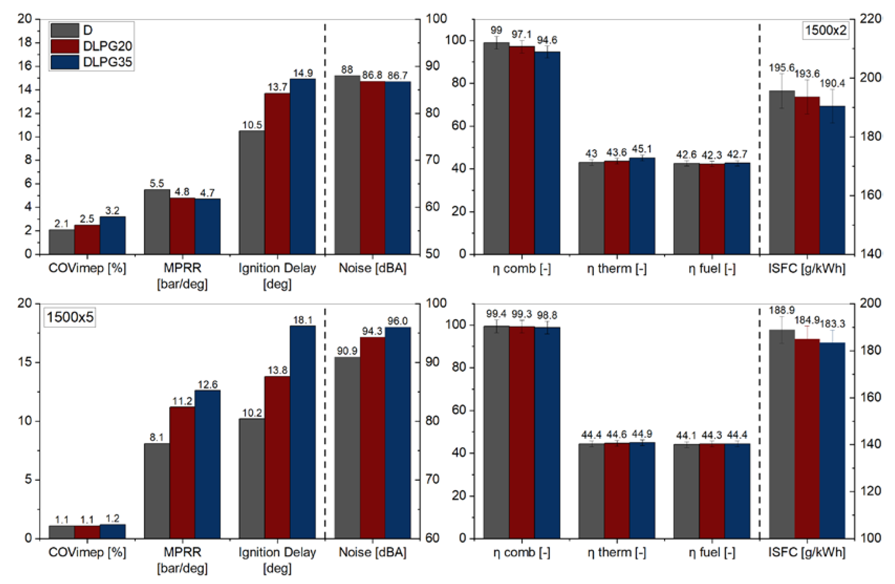
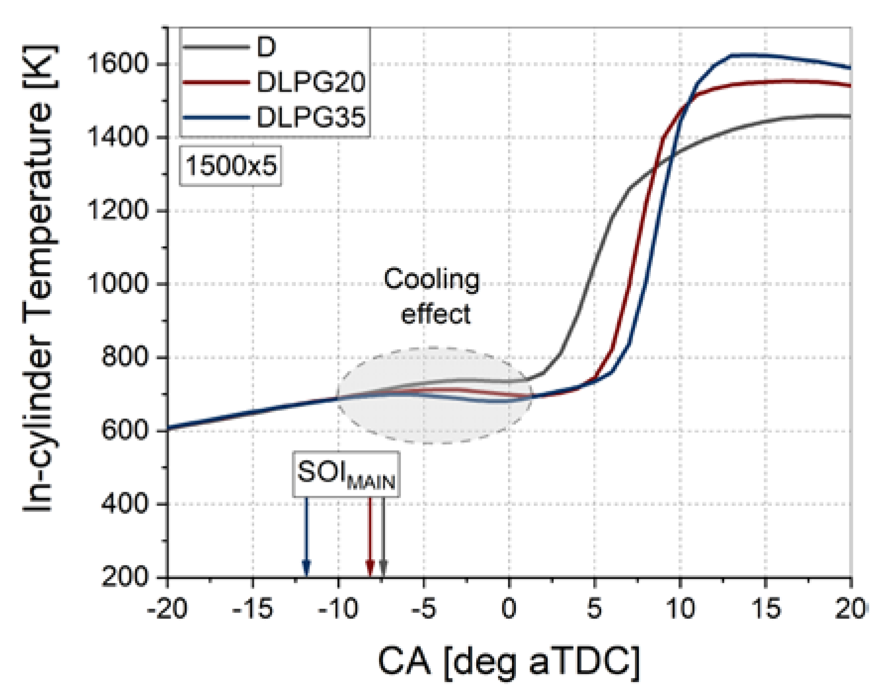
3.2. Combustion Analysis

In this section, the assessment of the fuel blends’ performance on combustion characteristics and emissions is regarded at 1500 rpm. For each DLPG blend, and each operating point, the EGR and the SOI levels were varied to achieve the NOx and combustion center targets.
Figure 5 shows the in-cylinder pressure, rate of heat release (HRR), and the injection pattern for operating 1500 × 2 and 1500 × 5 at constant MBF50 and NOx emissions. Advancement of the injection pattern is needed for the blends to achieve the MBF50 reference value, increasing the premixed combustion phase, combustion peaks and burning rates as illustrated in Figure 5. At higher loads, the LPG effect is even more evident. Indeed, the lower cetane rating of the blends increases the chemical delay and confirms an overall longer ignition delay of 3-4 degrees and 5-8 degrees (Figure 6), for DLPG20 and DLPG35, respectively.
Figure 5 provides a further representation of the combustion duration (MBF10-90) for diesel and LPG blends. Moreover, the effect of varying the engine load on the angular ignition delay can also be drawn. It increases with the load due to the cooling effect of LPG, which in turn lowers the in-cylinder charge temperature proportional to the fuel amount. The LPG cooling effect is detectable in the interval −10 to 5 CA, as also demonstrated in Figure 6, which distinguishes a reduction of the in-cylinder temperature up to a maximum of 30 and 60 °C for DLPG20 and DLPG35, respectively. In the case, the low-temperature heat release phase related to the pilot injection, practically disappear, being involved almost entirely into the main combustion phase. As the engine load increases, the higher ignition delay and then the premixed combustion phase reduce the combustion duration with advantages in terms of cycle conversion efficiency, as shown in Figure 6. The efficiency benefits are confirmed with an indicated specific fuel consumption (ISFC) reduction, as shown in Figure 6, of about 1–2% for DLPG20 and 3% for DLPG35. Slight differences in terms of combustion are observed at 2 bar of load, while at 5 bar, the prominent premixed phase, in comparison to only diesel case, causes an increase of the maximum pressure rise rate (MPRR) and noise combustion. For both blends, the combustion noise values are over the acceptable “comfort” limit of 90 dBA [10], and to reduce it, a more complex multi-injection pattern [4], out of the scope of this study, is required. The covariance of indicated mean effective pressure (COVIMEP), as an indicator of the cycle-to-cycle combustion process stability, shows any significant drift in comparison to diesel.
Figure 6 also displays combustion efficiencies (ηcomb). Despite the consistent differences at lower loads, at higher loads, they are not significant, and in the range of variation of 0.5%. The lower ηcomb is a consequence of the higher CO and HC emissions explicable by the worsening of the air–fuel spray interaction inside the combustion chamber and linked to the presence of over-lean regions and fuel trapped into the crevices [14]. HC and CO emissions will be further discussed in the following paragraphs. Indeed, at higher loads, the higher adiabatic in-cylinder conditions temperatures convert more CO into CO2 while comprehensively oxidizing the fuel.
The thermal efficiency, ηtherm, being a function of, among other parameters, the exhaust temperature shows a trend in which the blends have an advantage over diesel [15]. In particular, at 2 bar of BMEP, the ηtherm increase of about 0.6% and 2.1% for DLPG20 and DLPG35, respectively. The increase, as explained before, relates to the blends cooling effect on the in-cylinder charge temperature before the combustion, as illustrated in Figure 7, making the combustion more premixed [16]. The global efficiency (ηfuel) shows approximately the same trend as ηtherm. The relationships for the calculation of efficiencies are reported in Appendix B.
The following analysis discusses the LPG effects on the overall performances in terms of specific emissions at constant engine-out NOx. For an easier comparison among the blends, the results are reported in Figure 8 as radar plots. DLPG20 and DLPG35 are compared with diesel at the same engine calibration and the NOx engine-out emissions.
Figure 8 displays the specific emissions for all test points and fuels. The blends show a relevant increase of HC emission, and in particular using DLPG35. At engine load 2 bar, they are about two times higher than diesel, while at the highest load, DLPG20 has values as diesel, and only for DGPL35, the values are higher by about 50%. This is attributed to its ignition-related properties, evaporation behavior, and blends composition. The higher CO emissions related to the LPG mass ratio is observed for both tested points because of the longer ignition delay of LPG blends, which causes overmixing due to the evaporation characteristics combined with the relatively high engine swirl number [7]. The smoke emissions reduction is significant compared to diesel and in the range 94–99%. The reduced in-cylinder fuel-rich zones or any exposure to high-temperature combustion products are a precondition for the reduction of soot. Due to the high volatility of LPG, which in the vapor phase reaches high specific volumes, it probably inhibits the formation of fuel-rich areas, soot precursor. Therefore, based on the results obtained, it can be observed that the spray formation using a diesel-LPG mixing is sufficiently inclined to resist the formation of smoke [7]. Indeed, a higher hydrogen/carbon ratio characterizes the tested LPG blends compared to the diesel one (Table 2), with benefits on CO2 emissions that combined with the higher thermal efficiencies lead to higher efficiencies, proportional to the LPG amount, and up to 10%, for the blends. The EGR rates do not vary regardless of the fuel used for all tested points in the range 35–40%.

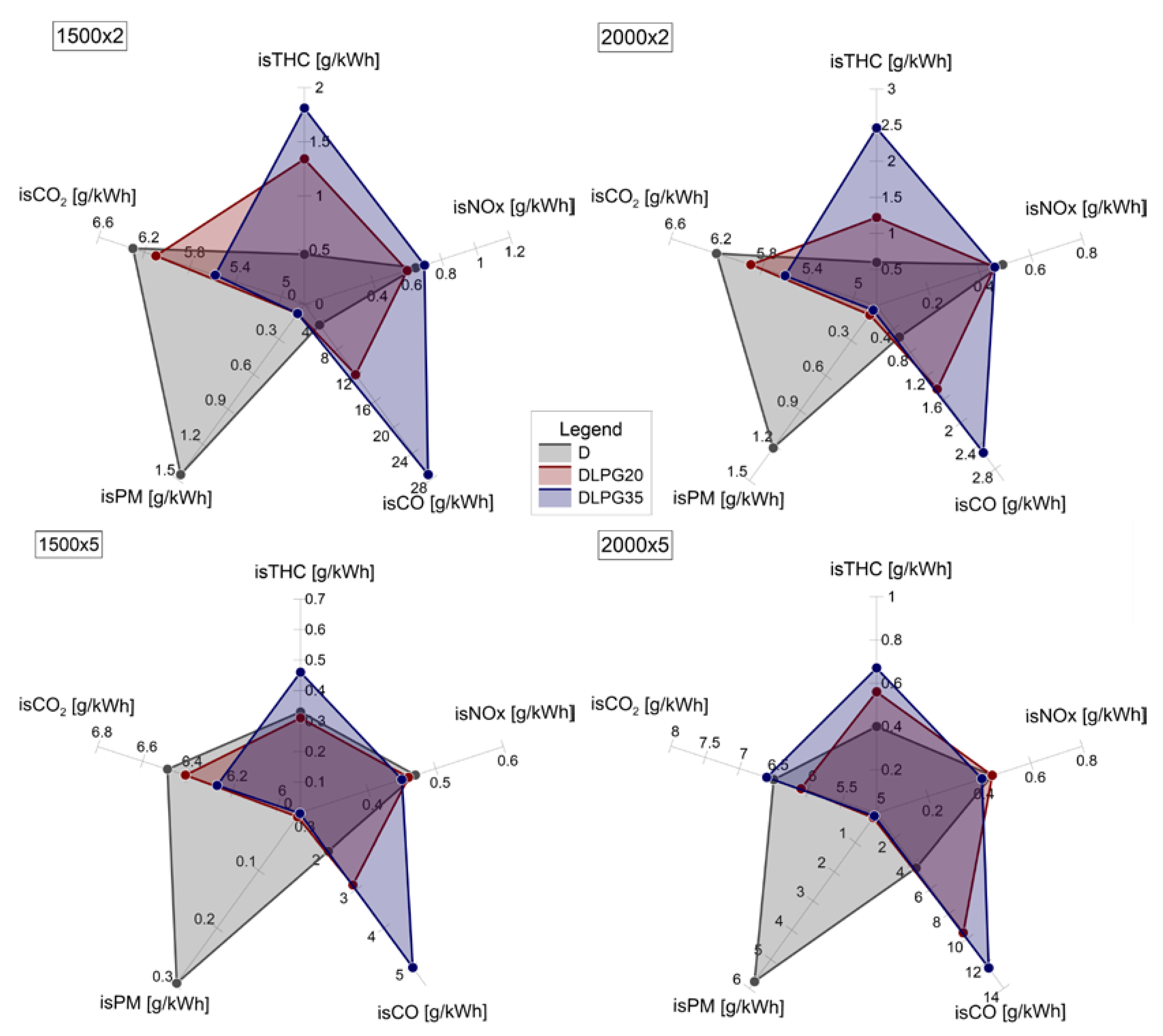
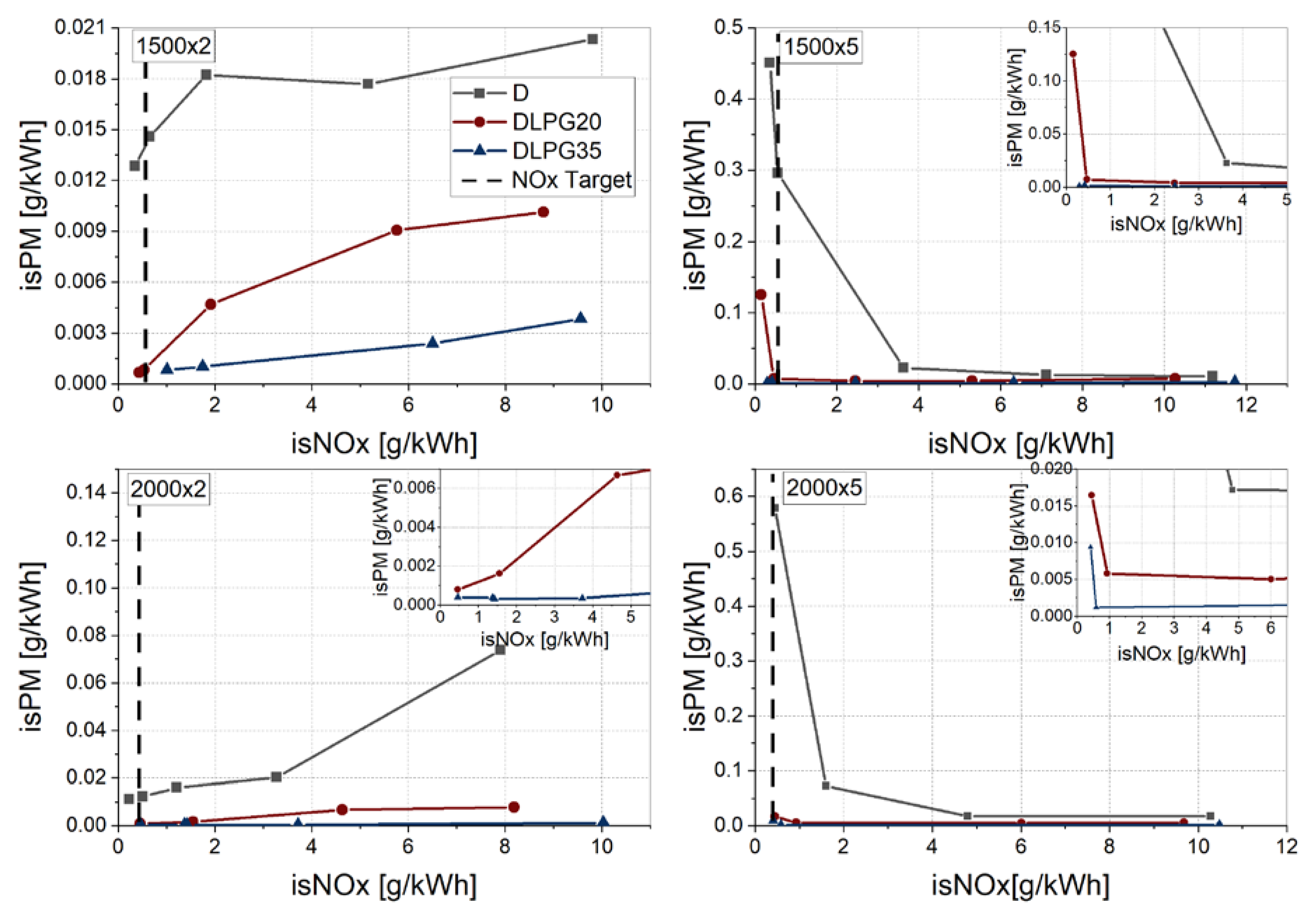
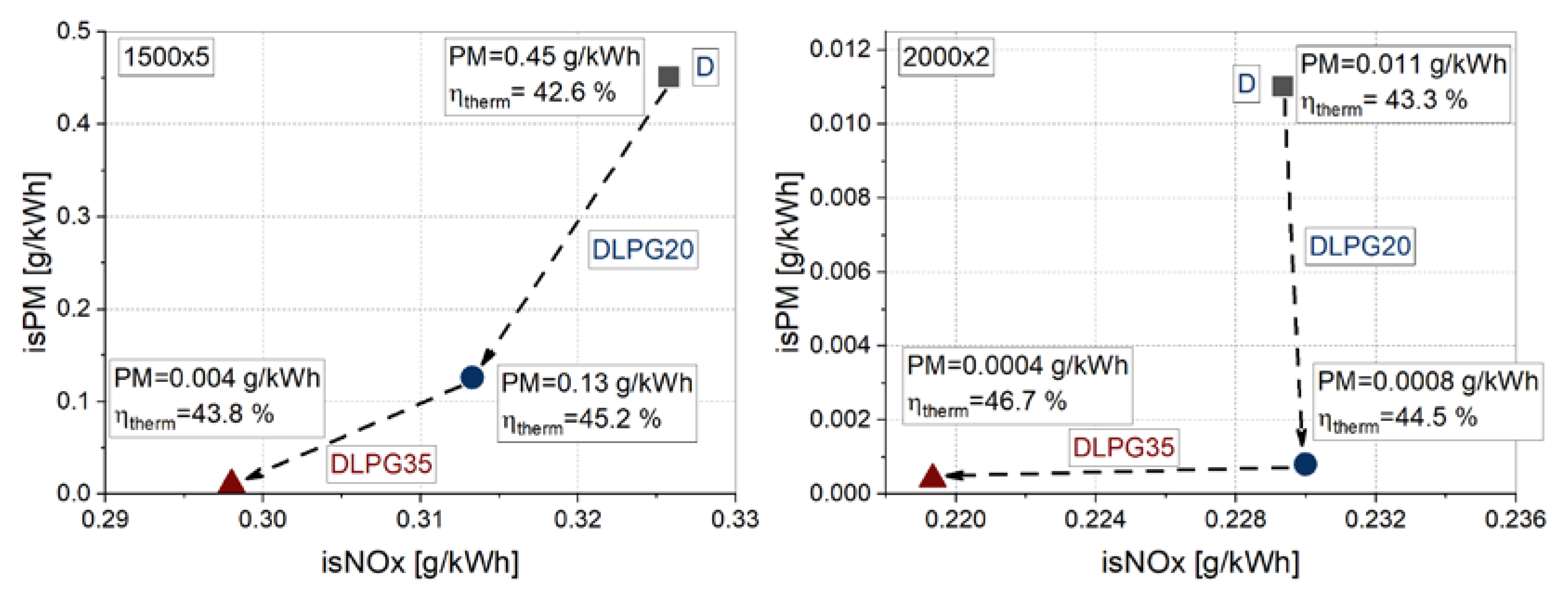
3.3. Trade-Offs by Exhaust Gas Recirculation (EGR) Sweep

The effect of diesel-LPG blends on the PM reduction effectiveness was carried out employing EGR sweeps at different engine loads and speeds. The PM emissions of all key-points plotted against the NOx values are shown in Figure 9. The engine operating conditions (intake pressure, rail pressure, exhaust backpressure, intake temperature) were the same during the tests. Dashed lines, representative of the post-Euro6 NOx target, are displayed and used as a reference for the specific comparison. As shown in Figure 9, the trade-off based on diesel, showing high levels of PM and NOx for all tested points, is drastically improved, employing the LPG blend fuel, in the range 90–95% in PM, depending on the load. By adopting the highest EGR rate in the case of blends, characterized by lower cetane numbers and lower evaporation temperatures, both NOx and PM were reduced simultaneously below reference targets.
In particular, significant benefits are shown at a higher load, of about 95% in terms of PM is observed. This result is significant considering that, these points are particularly critical for PM engine control, and is one of the operating points with the greatest contributing factor in applying an emission estimation procedure of the test emission cycle [17,18]. Therefore, the PM emission index improvement in these points appear significantly favorable for the engine performance over the WLTP procedure when the LPG blend is used.
In deeper detail, Figure 10 shows the detailed trend in the post-Euro6 region, as well as the zoom of the area highlighted in the previous figure. The PM benefit by adopting the highest EGR ratio is explored, and corresponds to the last trade-off point of Figure 9. The test points of 1500 × 5 and 2000 × 2 are reported. Starting from the diesel reference, adopting the DPLG20 a PM reduction of 70% in 1500 × 5 and 93% for 2000 × 2 is observed at the same engine calibration setup. By increasing the LPG percentage up to 35%, a further reduction of 93% and 50% is obtained for 1500 × 5 and 2000 × 2, respectively. In general, soot-less levels can be achieved without deterioration of thermal efficiency, indicated in the box (Figure 10) for each tested point, thanks to the promotion of the premixing thanks to the LPG blends. The effectiveness shown allows reaching very low PM emissions in the whole operating range. The LPG blend guarantees significant benefits even in the engine operating areas where the NOx values are very low, and soot control particularly sensitive. It is proper to specify the PM results obtained by using the LPG blends are close to the limit-sensitive thresholding of the instrument used. For this reason, future characterization with appropriate tools will be performed, such as a fast particle analyzer or micro-soot sensor.

4. Conclusions

A comprehensive engine test investigation using LPG–diesel blends was carried out. The approach and the tests were designed and aimed at demonstrating the feasibility and the potential of the application of a new concept using LPG–diesel blends with any injection system modifications.
  • The first part of the activity was devoted to analyzing the effects of using LPG diesel blends with a conventional common rail diesel injector. The hydraulic characterization assessed the effects of the different compressibility and viscosity of the blends, causing an increase in the injection duration, estimated to be approximately 0.1 ms for both tests carried out. On the other hand, a reduction of the hydraulic delay of 0.35–0.4 ms, and proportionally to the LPG content in the blend, was noted. Therefore, fuel-injected values for almost double the diesel amounts are observed, at the same ET, by using the LPG blend. In general, the blends do not alter the injector performance except for the different opening and closing delays, which can be solved through an appropriate calibration of the engine map.
  • Concerning the engine test campaign, the results confirmed the need for optimizing the conventional injection strategy (pilot-main) to be appropriate for the DLPG application. Indeed, the lower CN of the DLPG seems critical for HC emissions and combustion efficiency. Optimization should be oriented to improve the charge reactivity during the low-temperature heat release phase and shape the premixed combustion phase for combustion noise control.
  • It is worth highlighting that LPG blends are very effective in PM emission suppression that is about 90–95% at very low NOx targets. Acceptable penalties on HC and CO are detected. Based on the presented results, DLPG20 is the best fuel compromise between engine performance and emissions at a constant engine setting.
  • In general, soot-less levels can be achieved without deterioration of the thermal efficiency and test-to-test repeatability (COVIMEP), thanks to the promotion of the premixing thanks to the LPG blends.
Future activities will be addressed to develop the fuelling system, with reference to the design and realization of a proper fuel mixing system able to vary in real-time the fuel blending ratio. Then, further activities will be oriented to optimize the engine calibration setting in the whole engine operating area to evaluate the full potential of applying this new concept.

Author Contributions

Data curation, R.I.; investigation, R.I. and G.D.B.; methodology, M.C.; supervision, C.B.; writing—original draft, R.M. All authors have read and agreed to the published version of the manuscript.

Funding

This research received no external funding.

Acknowledgments

The authors would like to acknowledge C. Rossi, B. Sgammato and A. Schiavone for their technical support.

Conflicts of Interest

The authors declare no conflict of interest.

Definitions/Abbreviations

BMEPBrake Mean Effective Pressure
CACrank Angle Degrees
CICompression Ignition
COCarbon Monoxide
CO2Carbon Dioxide
cylcylinder
ECEnergizing Current
EGRExhaust Gas Recirculation
ETEnergizing Time
degdegree
HCHydrocarbons
HRRHeat Release Rate
IMEPIndicated Mean Effective Pressure
IMEPCOVCovariance of IMEP
isXIndicated Specific Emissions
ISFCIndicated Specific Fuel Consumption
LHVLower Heating Value
LPGLiquefied Petroleum Gas
MBFMass Burning Fraction
MBF10-90Combustion Duration
MBF5050% Mass Burning Fraction
MPRRMaximum Pressure Rise Rate
NOxNitrogen Oxide
pbackBackpressure
PFIPort Fuel Injection
PMParticulate Matter
prailRail Pressure
PcylIn-Cylinder Pressure
QInjected amount
ROIRate of Injection
SCESingle-Cylinder Engine
SOIStart of Injection
TDCTop Dead Centre
WLTPWorldwide Harmonized Light Vehicles Test Procedure
ηcombCombustion efficiency
ηfuelGlobal efficiency
ηthermalThermal efficiency

Appendix A

The fuel consumptions for both tested fuels are calculated by the carbon balance method using measured emissions of carbon dioxide (CO2) and other carbon-related emissions (HC, CO). The equation is shown below:
= 2 n O 2 n p x ˜ H 2 O + n p ( 1 x ˜ H 2 O ) ( x ˜ C O * + 2 x ˜ C O 2 * + 2 x ˜ O 2 * + x ˜ N O * + 2 x ˜ N O 2 * ) r
where the dry and wet mole fraction are linked by:
x ˜ i = ( 1 x ˜ H 2 O ) x ˜ i *
and
n p = n x ˜ C H b a + ( 1 x ˜ H 2 O ) ( x ˜ C O * + x ˜ C O 2 * )
x ˜ H 2 O = m 2 n x ˜ C O * + x ˜ C O 2 * [ 1 + x ˜ C O * ( K x ˜ C O 2 * ) + ( m 2 n ) ( x ˜ C O * + x ˜ C O 2 * ) ]
x ˜ H 2 = x ˜ H 2 O   x ˜ C O * K x ˜ C O 2 *
x ˜ N 2 = 3.773   n O 2   n p ( 1 x ˜ H 2 O ) ( x ˜ N O * + x ˜ N O 2 * ) 2
For species i, the wet molar fraction is indicated as x ˜ i , while x ˜ i * , the dry molar fraction; x ˜ C H b / a is the wet molar fraction of HC concentration. K varies in the range 1.5–5.5 for lean mixtures, while for the stoichiometric one from 2.5–4.5. It is possible to calculate the fuel amount based on the experimental airflow data.

Appendix B

The relationship for the calculation of the global (ηfuel) and combustion (ηcomb) efficiencies are:
η c o m b = 1 m m i x · L H V m i x Q l o s t ( H C , C O )
η f u e l = 1 I S F C · L H V m i x
where:
L H V m i x = x · L H V L P G + ( 1 x ) · L H V D   [ k J k g ]
I S F C = m m i x P i n d   [ g k W h ]
The percentage of the LPG in the blend has been quantified on mass basis (x) in according to the following equation:
x = m L P G m L P G + m d

References

  1. CO2 Emissions from Cars: Facts and Figures. Available online: https://www.europarl.europa.eu/pdfs/news/expert/2019/3/story/20190313STO31218/20190313STO31218_en.pdf (accessed on 18 April 2019).
  2. Martin, J.; Boehman, A.; Topkar, R.; Chopra, S.; Subramaniam, U.; Chen, H. Intermediate combustion modes between conventional diesel and RCCI. SAE Int. J. Engines 2018, 11, 835–860. [Google Scholar] [CrossRef]
  3. Di Blasio, G.; Belgiorno, G.; Beatrice, C. Effects on performances, emissions and particle size distributions of a dual fuel (methane-diesel) light-duty engine varying the compression ratio. Appl. Energy 2017, 204, 726–740. [Google Scholar] [CrossRef]
  4. Marialto, R.; Sequino, L.; Di Blasio, G.; Cardone, M.; Beatrice, C.; Ianniello, R.; Fontana, G. Combustion and Emission Characteristics of a Diesel Engine Fuelled with Diesel-LPG Blends. SAE Tech. Pap. 2019. [Google Scholar] [CrossRef]
  5. Cardone, M.; Mancaruso, E.; Marialto, R.; Sequino, L.; Vaglieco, B.M. Characterization of Combustion and Emissions of a Propane-Diesel Blend in a Research Diesel Engine. SAE Tech. Pap. 2016. [Google Scholar] [CrossRef]
  6. Aydin, M.; Irgin, A.; Çelik, M.B. The impact of diesel/LPG dual fuel on performance and emissions in a single cylinder diesel generator. Appl. Sci. 2018, 8, 825. [Google Scholar] [CrossRef] [Green Version]
  7. Alam, M.; Goto, S.; Sugiyama, K.; Kajiwara, M.; Mori, M.; Konno, M.; Motohashi, M.; Oyama, K. Performance and Emissions of a DI Diesel Engine Operated with LPG and Ignition Improving Additives. SAE Tech. Pap. 2001. [Google Scholar] [CrossRef]
  8. Mancaruso, E.; Marialto, R.; Sequino, L.; Vaglieco, B.M.; Cardone, M. Investigation of the Injection Process in a Research CR Diesel Engine using Different Blends of Propane-Diesel Fuel. SAE Tech. Pap. 2015. [Google Scholar] [CrossRef]
  9. Cao, J.; Bian, Y.Z.; Qi, D.H.; Cheng, Q.; Wu, T. Comparative investigation of diesel and mixed liquefied petroleum gas/diesel injection engines. Proc. Inst. Mech. Eng. Part D J. Automob. Eng. 2004, 218, 557–565. [Google Scholar] [CrossRef]
  10. Ma, Z.; Huang, Z.; Li, C.; Wang, X.; Miao, H. Effects of fuel injection timing on combustion and emission characteristics of a diesel engine fueled with diesel- propane blends. Energy Fuels 2007, 21, 1504–1510. [Google Scholar] [CrossRef]
  11. Bosch, W. The Fuel Rate Indicator: A New Measuring Instrument for Display of the Characteristics of Individual Injection. SAE Tech. Pap. 1966, 660749. [Google Scholar] [CrossRef]
  12. Montanaro, A.; Allocca, L.; Beatrice, C.; Ianniello, R. Outwardly Opening Hollow-Cone Diesel Spray Characterization under Different Ambient Conditions. SAE Tech. Pap. 2018. [Google Scholar] [CrossRef]
  13. Litzinger, T.; Stoner, M.; Hess, H.; Boehman, A. Effects of oxygenated blending compounds on emissions from a turbocharged direct injection diesel engine. Int. J. Engine Res. 2000, 1, 57–70. [Google Scholar] [CrossRef]
  14. Rakopoulos, D.C.; Rakopoulos, C.D.; Kakaras, E.C.; Giakoumis, E.G. Effects of ethanol–diesel fuel blends on the performance and exhaust emissions of heavy duty DI diesel engine. Energy Convers. Manag. 2008, 49, 3155–3162. [Google Scholar] [CrossRef]
  15. Sanli, A.; Ozsezen, A.N.; Kilicaslan, I.; Canakci, M. The influence of engine speed and load on the heat transfer between gases and in-cylinder walls at fired and motored conditions of an IDI diesel engine. Appl. Therm. Eng. 2008, 28, 1395–1404. [Google Scholar] [CrossRef]
  16. Al-Hasan, M. Effect of ethanol–unleaded gasoline blends on engine performance and exhaust emission. Energy Convers. Manag. 2003, 44, 1547–1561. [Google Scholar] [CrossRef]
  17. Di Blasio, G.; Belgiorno, G.; Beatrice, C. Parametric Analysis of Compression Ratio Variation Effects on Thermodynamic, Gaseous Pollutant and Particle Emissions of a Dual-Fuel CH4-Diesel Light Duty Engine. SAE Tech. Pap. 2017. [Google Scholar] [CrossRef]
  18. Di Blasio, G.; Bonura, G.; Frusteri, F.; Beatrice, C.; Cannilla, C.; Viscardi, M. Experimental Characterization of Diesel Combustion Using Glycerol Derived Ethers Mixtures. SAE Int. J. Fuels Lubr. 2013, 6, 940–950. [Google Scholar] [CrossRef]
Figure 1. Detailed scheme of the fuel-injection system [4].
Applsci 10 04949 g001
Figure 2. Single-cylinder engine (SCE) test cell layout.
Applsci 10 04949 g002
Figure 3. Engine operating points in the area of interest for this test campaign.
Applsci 10 04949 g003
Figure 4. Mass flow rate (c,d), energizing current (a,b), and fuel amount (table) for all fuels.
Applsci 10 04949 g004
Figure 5. Pressure, rate of heat release (HRR), injection energizing pattern, and combustion duration at 1500 × 2 (a) and 1500 × 5 (b) at constant engine-out NOx.
Applsci 10 04949 g005
Figure 6. Covariance of indicated mean effective pressure (COVIMEP), maximum pressure rise rate (MPPR), ignition delay, and noise (left) and efficiency performances (right) for all test points.
Applsci 10 04949 g006
Figure 7. LPG cooling effect at 1500 × 5.
Applsci 10 04949 g007
Figure 8. Specific emissions comparison among all fuels and operating points.
Applsci 10 04949 g008
Figure 9. Specific trade-offs NOx-particulate matter (PM) by exhaust gas recirculation (EGR) sweep for all operating points and fuels. The dashed lines are indicative of post-Euro6 levels.
Applsci 10 04949 g009
Figure 10. NOx-PM by varying the fuel at the highest EGR rate at 1500 × 5 and 2000 × 2.
Applsci 10 04949 g010
Table 1. SCE characteristics.
ParametersUnitsSpecifications
Specific displacementl/cyl0.5
Bore × Stroke mm82 × 90.4
Compression Ratio-16.5
Valves per cylinder-4
Nozzle hole number-7
Nozzle cone opening angledeg155
Actuating type-Solenoid
Table 2. Fuels proprieties of diesel–liquefied petroleum gas (LPG) blends [4].
Fuel NameDIESELDLPG20DLPG35LPG
LPG content w/w [%]02035100
Liquid density [kg/m3]836772723514
Mass LHV [MJ/kg]42.543.243.846.1
Heat of evaporation [kJ/kg]260294320430
Stoichiometric /F [-]14.6715.415.616.7
Boiling point [°C]362--−42
Autoignition Temperature [°C]250--365–470
H/C [-]1.92.32.53.4
Kinematic viscosity [m2/s]2.5 × 10−65.0 × 10−66.9 × 10−61.5 × 10−5

