Article

Experimental Comparison of Diesel and Crude Rapeseed Oil Combustion in a Swirl Burner

Department of Energy Engineering, Faculty of Mechanical Engineering, Budapest University of Technology and Economics, Műegyetem rkp. 3., 1111 Budapest, Hungary
Appl. Sci. 2020, 10(14), 4907; https://doi.org/10.3390/app10144907
Submission received: 29 June 2020 / Revised: 15 July 2020 / Accepted: 15 July 2020 / Published: 17 July 2020
(This article belongs to the Special Issue Applications of Alternative Fuels)

Abstract

:

Featured Applications

Gas turbines, boilers, small-scale combined heat and power generation.

Abstract

In pursuing maximum energy efficiency, local utilization of various crude fuels came into view. The present paper compares the combustion characteristics of standard diesel oil and crude rapeseed oil; the latter is an excellent model for high-viscosity liquid fuels. The combustion tests were performed in a 15 kW atmospheric turbulent swirl burner; the liquid fuels were atomized by a plain-jet airblast atomizer. Firstly, the acoustic signal is evaluated, since the instabilities of swirl combustion are accompanied by characteristic pressure fluctuations. The spectral analysis was performed by Wavelet transform, which fits excellently to the acoustic spectrum of combustion noise. This multi-scale technique features increased spectral resolution at lower frequencies at the expense of lower temporal resolution, providing excellent performance at both low-frequency, well-localized components and high-frequency, broadband phenomena. The joint probability density function of two characteristic frequencies was plotted with the result that flame acoustics match for the two fuels. Secondly, their pollutant emissions were compared and evaluated under similar conditions with the conclusion that crude rapeseed oil can substitute diesel oil in a limited operating range. Note that the distinct material properties already mean differences in all atomization, evaporation, and mixing characteristics, hence, the latter result is not intuitive.

1. Introduction

Renewable liquid fuel utilization has a turbulent history with a general conclusion that our energy demand massively surpasses the potential of arable fields. Fuel crop production, the source of first-generation biofuels, endangers food security [1]. It is predicted by the IEA that oil utilization for power generation will drop in the future [2], however, biofuels for transportation are on a stable incline [3], highlighting aviation [4]. These all can be realized by using waste-to-fuel technologies, like producing biodiesel from waste cooking oil [5], harvesting algae ponds [6], and using peak shaving to convert electricity into fuel when there is excessive power available from principally renewable sources [7]. These three examples are the second, third and fourth generation of biofuels, respectively. The relevance of liquid fuels in the future of energy is secured by their high power-to-weight ratio, i.e., battery development is approaching 1 MJ/kg energy density, while the lower heating value of liquid hydrocarbons is exceeding 40 MJ/kg [8]. Even though the loss during energy conversion is higher for combustion engines, the difference makes it evident that liquid fuels will remain in active use for decades in both transportation and aviation. The few-factor difference in the offered mileage of a vehicle is due to physical limits, since more energy can be stored in hydrocarbon molecules than in ions. Consequently, liquid fuel combustion research is still a critical field, regardless of negative mainstream media communications. To reduce our dependence on fossil fuels, local utilization of alternative energy sources requires a well-established background to help the industry to exploit them. Due to the wide range of physical and chemical properties of alternative fuels, understanding the similarities and differences compared to conventional fuels is essential to safely perform the increase in the renewable content or change to a fully alternative fuel operation.
Most renewable fuels are oxygenated by their nature [9], which is favorable from the pollutant emission point of view in internal combustion engines [10]. The renewable fuels can be light (LRF), such as alcohols [11,12] or heavy (HRF), like animal fat [13], pyrolysis oil and straight vegetable oils [14,15]. Representatives of the former category are significantly easier to utilize; the currently available technologies are capable of handling them. Nevertheless, chemical compatibility issues might require alternative materials in the fuel system [16]. HRF types require special care. For instance, either the burner [17] or the atomizer [18] may feature depositions over time, which should be addressed to avoid extremely short maintenance intervals. The advantage of liquid fuels is that they can be easily stored and transported. Consequently, they are excellent in increasing the electrical supply safety; hence, thermal power plants running on gaseous fuel can usually seamlessly switch to liquid fuel. The chemical conversion of crude vegetable oils to lighter fuel types [9] solves numerous operational problems, such as poor spray quality, insufficient evaporation and, hence, inadequate fuel-air mixing. These issues all lead to a bad fuel economy combined with increased pollutant emissions. Even though the way forward seems clear, building a biorefinery in less-populated rural areas might lead to an increased carbon footprint overall, and the high investment costs might not be returned at all [19]. Therefore, the direct utilization possibilities of HRF should be addressed. For this purpose, the combustion of standard diesel oil and crude rapeseed oil were compared. The latter fuel is an excellent representative of HRF; not only rapeseed oil combustion can profit from the present study.
An overview of HRF utilization by fellow researchers and their key findings is shown in Table 1. The conclusion is the following: stable combustion is possible up to a few times ten percent HRF content, but more concentrated blends usually result in either unstable operation or excessive pollutant emission. However, novel concepts offer seamless operation. The key challenges of HRF combustion are summarized in the following.
The very first process in liquid fuel combustion is atomization. Highly viscous liquids show a significantly lower tendency to breakup [26]. To overcome this issue, there are three ways. The first one is using water-oil emulsion, which features micro-explosions when heated above the boiling point of the water [27]. The resulting very fine spray evaporates quickly, and the presence of H2O molecules near the fuel also helps in reducing the NOX emission by lowering the concentration of atomic oxygen [28]. The nearly double heat capacity of H2O compared to CO2 and N2 lowers the adiabatic flame temperature as well, prolonging the maintenance intervals. Nevertheless, the higher H2O concentration promotes hot corrosion of steel parts downstream. The downside of H2O addition is that a water purification plant is required to avoid the deposition of minerals inside the combustion chamber, leading to decreased heat transfer and contamination issues. A highly practical solution is the use of a unique atomizer [29]. Nevertheless, the traditional way is preheating the fuel to an adequate temperature range [30]. This solution is even more economical if the waste heat of combustion can be used for this purpose. Since there is no latent heat to cover, this versatile solution was also used in the present case. Atomization characteristics will be discussed in Section 2.2, based on an earlier work [31], which focused on the spray measurement of various liquids, including both the presently investigated diesel and crude rapeseed oils in a wide parameter range.
The second process is evaporation. Fuels with low volatility are almost impossible to ignite under atmospheric conditions, hence it is a common practice that the warmup and shutdown procedures of the combustion chamber are performed by using a conventional light fuel [18], such as diesel oil in transportation and natural gas in power generation. The evaporation of the above-mentioned water–oil emulsion, exploiting micro-explosions, was studied by Hsuan et al. [32], demonstrating the quicker evaporation of heavy fuel oil (HFO) sample compared to neat fuel utilization. The evaporation of heavy fuels is still less known, since the outer surface of the droplet might solidify even for kerosene gel [33]. Significant crust formation was similarly observed for HFO [34], featuring pores on the surface [35] where the oil inside left the droplet when evaporated. To overcome this issue, atomization with steam [30] might help, substituting air with an H2O atmosphere in the vicinity of the fuel nozzle. The drawback of this technology is that treated water is required, which is abundant in thermal power plants using steam turbines, but uneconomical for the majority of applications. Since the present study focuses on the combustion of crude rapeseed oil, its evaporation characteristics will not be covered in the latter part of this paper; it was published in an earlier study [36]. The purpose of this paragraph was to introduce the difficulties in heavy oil combustion, which usually lead to excessive emissions due to the inhomogeneous flame temperature field. HFO is much more viscous and less volatile than any HRF, nevertheless, the unsaturated bonds and the natural oxygen content both facilitate polymerization. Hence, a similar systematic study on HRF would lead to a better understanding of the proper conditions for their combustion. Consequently, the substitution of light and heavy fuels, even with proper preheating for favorable atomization characteristics, is far from trivial.
Modern combustion chambers, in which flame radiation is less favorable, highly lean mixtures in swirl burners are combusted [37] since the NOX concentration nearly doubles with every 50 K increase in flame temperature [38]. Such an operation is limited by thermoacoustic instabilities [39] besides the theoretical limit in air-to-fuel equivalence ratio, λ~2 for most hydrocarbon fuels [40]. Hence, the operating point should approach the lean blowout limitation as much as possible by design. It was found in an earlier work that stable combustion of crude rapeseed oil is confined to the weak swirl region in atmospheric combustion [41]. However, the acoustic characteristics of liquid fuel combustion are rare in the public literature, which was the primary motivation of this study.
The acoustic spectrum of V-shaped turbulent flames is confined below 1.5–2 kHz [42,43]; the dominant frequencies are located at a few hundred Hz [44,45]. However, with weak swirl, when the flame is straight, the combustion-related frequencies can also be found at higher frequencies [46]. In engineering practice, temporal signals are typically evaluated by using Fast Fourier Transform (FFT) [44]. Nevertheless, the spectrum contains significant noise besides fluctuating harmonic components. To overcome this issue, Wavelet transform (WT) can be used, which enables the use of various base functions [47]. The superiority of WT over FFT in combustion diagnostics was first published by Nair and Lieuwen [48]. Chaudhuri and Cetegen [49] followed their motivation for lean, non-swirl flames, analyzing the frequency domain up to 200 Hz. Dey et al. [50] used the WT of the CH* signal, sampled at 5 kHz, for the lean blowout prediction of a swirl-stabilized LPG flame. Idahosa et al. [51] also investigated a swirling propane flame, however, their frequency range was limited to 500 Hz. Note that the majority of the above-cited papers all focus on gaseous fuel combustion, hence data on liquid fuel combustion are already a novelty. The fundamental and practical details of the comparison of FFT and WT will be discussed in Section 2.3.
Substituting a conventional light fuel with HRF raises numerous practical questions. The scientific contribution of the present study is that it covers the required steps from fuel preparation through pollutant emission to acoustic noise analysis to highlight the possibilities of the direct substitution of standard diesel oil with crude rapeseed oil, which is an excellent representative of HRF. The acoustic signal of combustion was evaluated by using WT instead of the conventional FFT to compare the pressure signal. This step is also crucial in fuel substitution to avoid thermoacoustic instabilities, distinct heat release pattern, and hence combustion chamber damage. The present paper concludes that the pollutant emissions of crude rapeseed oil combustion exceed that of diesel oil, and the acoustic behavior is highly similar. Consequently, if the stable operation of a more viscous fuel can be provided, the substitution can be performed with a minimal impact on the acoustic conditions of the combustion chamber. The finding of the present study can be directly applied in combustion systems utilizing straight vegetable oils, e.g., in boilers, furnaces, and gas turbines. However, the general discussion of the method facilitates a better understanding of the requirements of alternative fuel utilization for several other applications.

2. Materials and Methods

This section starts with the introduction of the experimental setup, followed by the characterization of the swirl burner. Fuel atomization is detailed in the second subsection, also considering the effect of fuel preheating. The third subsection discusses the practical aspects of WT, highlighting its advantages over the commonly used FFT for the spectral analysis of combustion noise.

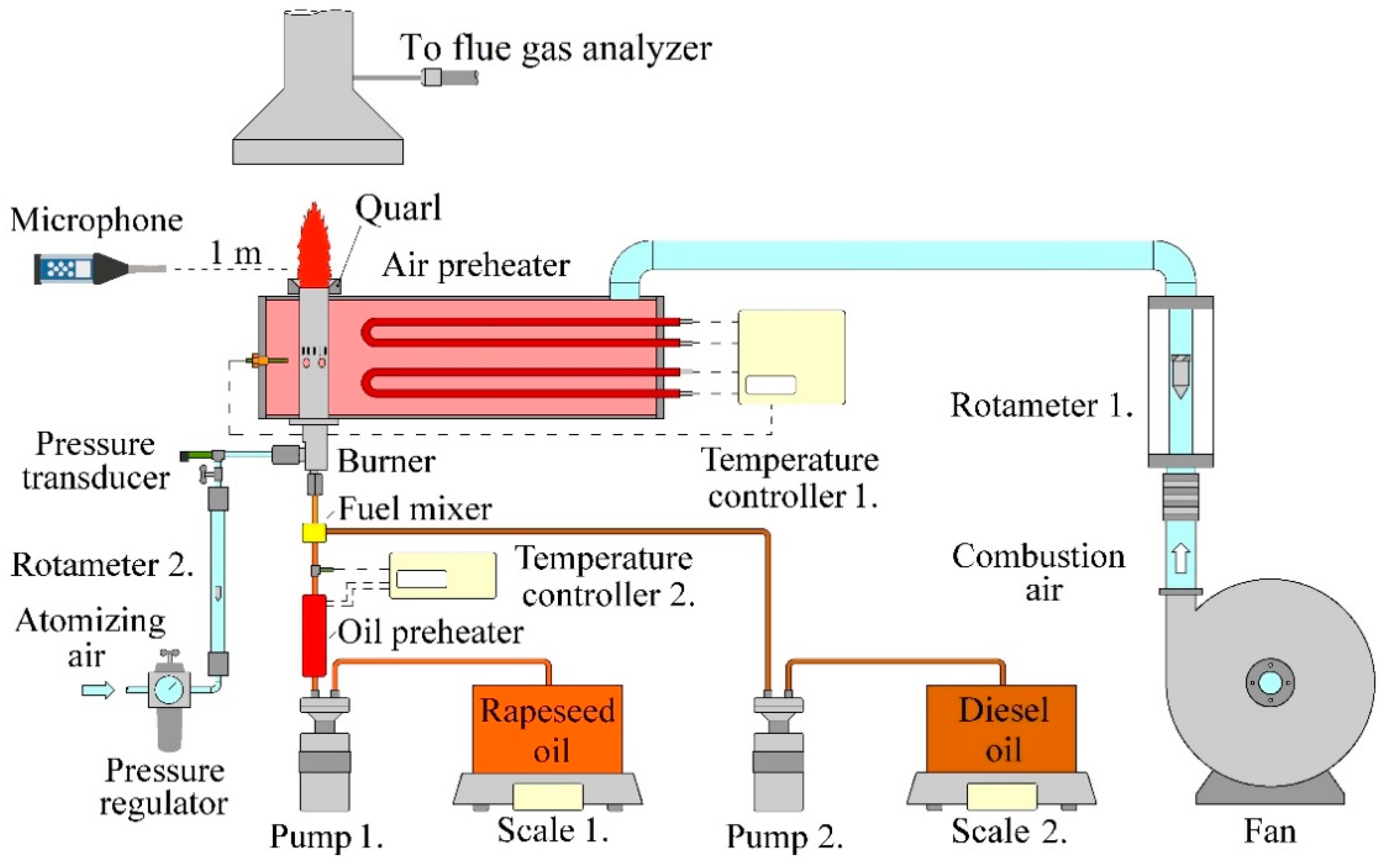
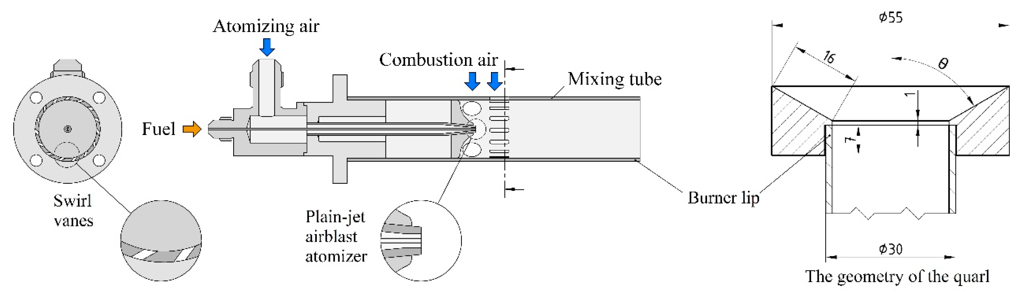
2.1. Experimental Setup

Figure 1 shows the atmospheric combustion test rig. The combustion air flow rate was controlled by a continuously adjustable frequency converter, determining primary λ, which is presented through the paper. The air flow temperature was increased to 400 °C by heater filaments before entering the burner. Standard diesel oil (D, EN590:2014) and crude rapeseed oil (R) were both pumped from their respective tanks to the fuel manifold. Since R has excessive viscosity at 20 °C, a liquid preheater increased its temperature to 150 °C to facilitate atomization and hence vaporization. The atomizing air was taken at 5 bar and 20 °C from the high-pressure air network of the laboratory. The combustion power was set to 15 kW in all cases. To enhance flame stability, quarls can be effectively used for swirl combustion [52]. In the present case, a 15° quarl with a 16 mm slant height was installed on the burner lip to extend the blowout limitation. However, it was used for comparison only in the case of diesel oil combustion, since crude rapeseed oil combustion was principally limited by low fuel evaporation through the swirl number, S [41]. The calculation of S is detailed in reference [46] for the present setup, while its definition is shown by Equation (1)
S = G φ / ( G x · R ) .  
where Gφ is the axial flux of the angular momentum, Gx is the axial thrust, and R is the inner radius of the burner. In the following, the burner without the quarl is further referred to as baseline (BL). Hence, diesel and rapeseed oil combustion in this configuration is noted as BL-D and BL-R. The setup with the 15° quarl is called Q15-D since the quarl was only effective in the case of diesel oil combustion. The reason to evaluate this case is the demonstration of the sensitivity of the combustion noise to the burner geometry. An SVAN 971 noise analyzer (Svantek, Warsaw, Poland) was placed at the height of the burner lip, 1 m away from the burner centerline. Its sensitivity was 28.74 mV/Pa, and the sampling rate was 12 kHz at 16 bit. The combined expanded uncertainty of both S and λ was below 5% at 95% level of significance in all the cases. A Testo 350 analyzer (Testo AG, Titisee-Neustadt, Germany) was used to measure the O2, NOX, and CO concentrations in the flue gas. The uncertainty of O2 measurement was 0.1 v/v%, while those of NOX and CO were below 10 ppm, also considering that all the pollutants were corrected to 15% O2 level.
The lean premixed prevaporized burner, which was used in a Capstone C-30 micro gas turbine (Capstone Turbine Corporation, Los Angeles, CA, USA) earlier, is shown in Figure 2. Its mixing tube is 75.5 mm long from the atomizer nozzle tip to the burner lip, and its inner diameter is 26.8 mm. The diameters of the atomizing air annulus are 0.8 mm inside and 1.6 mm outside. The inner diameter of the central fuel pipe is 0.4 mm. The lowest value of the atomizing gauge pressure, pg, of the plain-jet airblast atomizer was 0.3 bar, which was enough to avoid droplet combustion, and hence excessive pollutant emission. The elevated atomizing free jet is also reducing S through increasing Gx in Equation (1) besides generating a finer spray. The spray characteristics are discussed in detail in Section 2.2.
The burner features fifteen 45°, fixed swirl vanes; their cross-section is shown on the left side of Figure 2. Due to the fixed geometry, the swirl number increased with the combustion air flow rate. To avoid the accumulation of fuel droplets near the nozzle, hence the coking [53], four circular slots are located below the swirl vanes; they reduce S since they do not swirl the air. In the present case, the straight flame was observed at S < 0.52, which was followed by a transitory regime at 0.52 < S < 0.81. This regime was characterized by a sudden transition between straight and V-shaped flames at around 1 Hz. At S > 0.81, a fully developed V-shaped flame was observed, in accordance with the observations discussed in the literature [54]. Rapeseed oil combustion was limited to straight flame shape in this setup, i.e., to S < 0.52 [41]. A straight and a V-shaped flame are shown in Figure 3, which were recorded at two subsequent measurement points. The structure of the straight flame is helical, however, there is an outer recirculation zone (ORZ) and an inner recirculation zone (IRZ) in the case of V-shaped flames [55]. These torus-shaped flow structures are responsible for transporting back hot gas and reactive radicals to facilitate the ignition of the upstream mixture.
There were several parameters varied in this measurement setup. The most important ones from the theoretical combustion characteristics point of view are pg, λ, and S. Besides, the fuel type, and the used quarl are also noted in Table 2, summarizing all the evaluated configurations in this paper.

2.2. Atomization Characteristics

The purpose of atomization is to generate fine droplets that evaporate inside the mixing tube to supply the flame front with homogeneous fuel vapor-air mixture. Atomization is sensitive to both fluid dynamical and fuel properties. Hence, the relevant physical parameters are summarized in Table 3 at the respective fuel inlet temperatures. Rapeseed oil was preheated to 150 °C, principally, to reduce its viscosity to a similar value to that of diesel oil. Since the thermal power was identical and R is an oxygenated fuel, the required mass flow rate was slightly higher.
Estimation of the volume-to-surface diameter, SMD, requires the following non-dimensional numbers for airblast atomization [56]. The Ohnesorge number, Oh, is calculated from material properties and nozzle geometry as
Oh = μ F / ( σ · d 0 · ρ F ) 0.5
where µF is the dynamic viscosity of the fuel, σ is the surface tension, d0 is the inner diameter of the fuel pipe, and ρF is the density of the fuel. Oh was 0.0358 and 0.0367 for D and R, respectively. The fluid dynamical conditions are represented by the Weber number
We = w R 2 · d 0 · ρ A / σ
where wR is the relative velocity between the air and fuel, and subscript A represents air. Both wR and ρA were calculated by assuming an adiabatic expansion [36]. The last required non-dimensional number for SMD estimation is the air-to-fuel mass flow ratio, AFR. Now, SMD can be estimated as
S M D d 0 = ( A · We 0.5 + B · ( μ F / ρ F ) 25 ° C ( μ F / ρ F ) 150 ° C · Oh ) · ( 1 + 1 A F R )
where A = 0.477 and B = 0.35 for D and 0.2 for R are empirical constants determined for this atomizer. Nevertheless, it is envisioned that these parameters hold for other airblast atomizers as well [31].
Table 4 and Table 5 show the estimated SMD values and We and AFR for both fuels. Since the preheating of R decreased both the viscosity and surface tension below these parameters of D, and the densities are similar, SMD of R is slightly smaller than that of D at all pg values. As a consequence, their evaporation characteristics are also similar [36] if crust formation can be omitted, providing similar conditions for combustion. The slightly higher We of R compared to D is due to the lower σ. However, AFR decreases as identical thermal power requires a higher fuel flow rate of R due to the difference in their lower heating value.

2.3. The Continuous Wavelet Transform

The temporal pressure signal of Case 1 is shown in Figure 4a, where blowout occurs at 1 s. To gather spectral data, Fourier analysis is commonly used. Figure 4b shows the spectrogram of the above signal that consists of 214 samples at 12 kHz sampling frequency, i.e., 1.37 s. The previously mentioned FFT is excellent for steady operation, however, this transient state cannot be characterized well by this technique. Hence, the signal is cut into shorter parts, and FFT is performed on all of them, which is the Short-Time Fourier transform (STFT). The best resolution was achieved at a window size of 512 samples and 50% overlapping, which is still not ideal for identifying the governing dynamics that precede flame blowout.
The continuous wavelet transform (CWT) of the raw pressure signal is shown in Figure 4c by using a Morse wavelet (time-bandwidth product parameter: 60 and symmetry parameter: 3). The white dashed line sets a boundary for the cone of influence under which the edge effect might excessively bias the result, i.e., this region should be omitted from the evaluation. While the STFT is characterized by a homogeneous time-to-frequency window aspect ratio, the CWT provides poor time and fine frequency resolution at low frequencies, which ends up with the opposite in the high-frequency regime. The time-to-frequency aspect ratio continuously decreases by a factor of 2 in each step due to the high-pass filtering nature of the CWT [57]. Since frequencies well below 100 Hz are typically out of interest [58], the poor time resolution at lower frequencies does not affect the analysis. At a few hundred Hz, the temporal resolution reveals the amplitude fluctuations in the time domain, while the frequency resolution is ~20 Hz. Since combustion is a broadband phenomenon [59], accurate resolution in the frequency domain is not mandatory for control logic. The high temporal resolution also contributes to the understanding of the evolution of the frequency peaks. This phenomenon is facilitated by the variation in the speed of sound through the heat release oscillation.
Four frequencies are emphasized in the present study, following the representative results of Figure 4. They are f1 = 230 Hz, f2 = 500 Hz f3 = 1600 Hz, and f4 = 3200 Hz. The first two are associated with the recirculation zones in V-shaped flames, while the latter two dominate the straight flames. The peak near 200 Hz is typically in the focus of blowout and flame transfer function investigations of V-shaped flames [60,61,62].
To address the uneven behavior of the temporal series of CWT magnitudes in the scalogram, it is a possibility to filter the results to a single frequency, then perform a further transform on it. This procedure in FFT is well-known in the field of bearing diagnostics to find nonlinear signal sources, e.g., cracks in the rings or a damaged ball. This step removes the harmonic components, hence the non-periodic terms will remain. The scalogram of the CWT coefficients at f1 is shown in Figure 5, showing no apparent deterministic behavior. The effective frequency axis is practically limited to 115 Hz, according to the Nyquist–Shannon sampling theorem. The plots of other frequencies show largely different, similarly stochastic scalograms, even in the neighborhood. However, the histogram of the CWT coefficients turned to be a useful tool to characterize combustion. Naturally, the CWT coefficients vary in a closely stochastic way when the flame is present.
When blowout is approached, the emerging fluctuations due to the reigniting and downstream convected burning mixture [48] result in low CWT coefficients since the inspected frequency associated with the given mode is not fed. Therefore, the histogram is dominated by the low-amplitude coefficients. CWT seems a better choice, nevertheless, the former method is computationally intensive, following a power law. The analyzed 214 samples took 556 ms for the CWT algorithm, which still allows a real-time signal analysis. Nevertheless, the process was finished in 3.6 ms in the case of STFT in the MATLAB (MathWorks, Natick, MA, USA) software environment. However, the Discrete Wavelet transform of a signal with a few selected frequency components is significantly faster, matching the computational time of the STFT.
Besides spectral analysis, other authors [63,64] have made significant achievements by counting the forbidden patterns in the acoustic signal and setting a threshold for blowout alarm. It has to be noted that this approach did not work properly for the presently evaluated liquid fuel combustion cases. Similarly, phase space attractors [65] failed to provide any consequent trend. This is the reason why only spectral transformation and temporal data analysis was performed in this work.

3. Results and Discussion

This section is divided into three parts. The first one details the acoustic signal of both BL-D and Q15-D in the case of various flame shapes and highly lean conditions, which precede flame blowout. Since it was proven in Section 2.3 that the results of a spectral transformation show chaotic behavior, flame characteristics require statistical analysis to derive the deterministic part of the pressure fluctuation signal, hence, both 1D and 2D (joint) histograms are used for acoustic data evaluation. The second subsection focuses on the comparison of R and D combustion, using 2D histograms. The third subsection discusses the pollutant emission analysis of the evaluated cases.

3.1. Spectral Analysis of Diesel Oil Combustion

All practical signals contain stochastic and deterministic parts. An efficient control system requires the proper filtering of the deterministic part, i.e., feeding it with a high signal-to-noise ratio. For this purpose, the probability of the measured temporal pressure signal is analyzed in this subsection. Figure 6 shows the histogram of the pressure signal of 214 datapoints of D combustion at the observed three flame shapes and right before the blowout, corresponding to Cases 2–5. Note that the latter state was also characterized by a V-shaped flame. All the histograms of the pressure signal follow a normal distribution, hence, a normal probability density function (PDF) was fitted to all subplots in Figure 6a by using the fitdist function of Matlab. This algorithm estimates the standard deviation through the unbiased estimate of the variance. A PDF is added to all further 1D histograms of the pressure signal, which follows a normal distribution as well.
The straight flame was dominated by higher frequencies, and its overall sound pressure level was also higher, as discussed in a previous work [46]. The noise emission of the transitory flame was similar, however, the V-shaped flame was characterized by lower noise, which decreased until blowout. This finding is also supported by the histograms as they became narrower as the blowout is approached. Figure 6b shows the joint histogram of the CWT coefficients at f1 and f2. The dominance of f1 over f2 is apparent in both the straight and V-shaped flames, as the distribution of the joint histogram is flatter in the horizontal direction. However, the CWT coefficients at f1 and f2 are closely equal in both the transitory and the V-shaped regime. A similar result was reached in cases where the flame blowout occurred in the straight flame shape with the modification in the characteristic frequencies, which were f3 = 1600 Hz and f4 = 3200 Hz.
The flame blowout occurred in the transitory regime in Case 1, which was shown in Figure 4 in detail. For comparison, the results of BL-D and Q15-D (Case 6) are shown in Figure 7, as the latter setup belongs to a stable flame, well below the blowout limitation. The difference is only the presence of a quarl. The histogram of the pressure signal is similar, however, Q15-D is flatter, and the large amplitude fluctuations drive the microphone electronics to saturation more often. This phenomenon is interesting since the microphone is capable of detecting 140 dB overall sound pressure level, Lp, while this value was only 97 dB in the present case, which is enormous as the scale is logarithmic. Moreover, the measurement series included straight flames with Lp > 100 dB without observing the saturation of the noise analyzer. The answer is the sudden change in flame shapes, occurring as a hammer blow, which is a subcritical Hopf bifurcation [58,66,67]. Hence, the change requires the passing of a certain threshold with hysteresis; then, there is a sudden jump in the mathematical characteristics.
The axis limits of the joint histograms in Figure 7 were doubled compared to those of Figure 6, while the number of bins was similarly 30 in both axes to cover a broader range in CWT magnitudes. In Case 1, the similar amplitudes of f1 and f2, which were observed previously, do not characterize the pre-blowout phase, as the joint histogram is not confined to lower amplitudes. Nevertheless, Case 6 shows a slightly more stochastic behavior with the dominance of f1, similar to BL-D. Consequently, flame blowout detection requires a deeper understanding of the signal structure of the given flame.
The joint histograms in Figure 6 showed that if the blowout is approached, the CWT coefficients decrease in Case 5. Figure 8 presents the histograms of both the pressure signal and CWT coefficients of f1 and f2 of Q15-D at subsequent measurement points (Cases 7–10), starting from the one where blowout occurred in Case 5. As blowout approaches, the PDF of the acoustic signal also shows a steepening distribution, similar to the blowout, even in Figure 6. The last stable point at λ = 2.01 already seems unstable based on both histogram plots, nevertheless, the blowout occurred at a slightly higher combustion air flow rate. It was mentioned earlier that a theoretical flammability limitation is λ~2 under atmospheric conditions. Consequently, a portion of combustion air passed the combustion zone, similar to the experiments of Hadef et al. [68] due to the high flow rates.
Concluding from the results, either a shape parameter of a fitted PDF or the decreasing CWT coefficients at characteristic frequencies imply flame blowout. Nevertheless, the computational effort required for the former method is significantly lower. It is free from the selection of frequencies, which may be different for various burner configurations.

3.2. Spectral Comparison of Diesel and Rapeseed Oil Combustion

In liquid fuel combustion, atomization, evaporation, and mixing with combustion air all impact the flame characteristics. Figure 9 shows the comparison of four BL-R, BL-D, and Q15-D setups (Cases 11–22) at the same measurement conditions. Since only the straight R flame was possible in the present measurement setup, the analysis is confined to the weak swirl regime. Since this flame shape was dominated by the higher frequencies, CWT coefficients at f3 = 1600 Hz and f4 = 3200 Hz were used in the joint histograms.
The results of BL-R and BL-D notably differ from that of Q15-D, showing that the geometry has a significant impact on the acoustic field. Apparently, f3 slightly dominates the combustion process over f4 in these cases, except in the last row, where they have nearly equal influence. BL-R and BL-D show similar characteristics, which means that acoustics has a low sensitivity on the fuel type in the presently investigated setup. In the light of the mentioned differences in Section 1 and Section 2, this is a satisfying result, as there is no need for an updated control algorithm for rapeseed oil combustion. Nevertheless, various fuels might have different stability characteristics, e.g., R was only stable at S < 0.52 in the present case. Experiments with Q15-R were also initiated, but failed since there was not enough heat transferred back to the upstream mixture as the flame diameter increased in the quarl.
It was proven that the governing frequencies of the two fuels show similar statistical behavior, hence thermoacoustic instabilities due to an alternative fuel are improbable. Nevertheless, depositions [17] and limited combustion stability [52] should be considered during the transition from conventional fuel to HRF. An open question for future research is the prediction and control of HRF flames near blowout. Such an investigation might notably benefit from the advantages of Wavelet transform over the widely used STFT.

3.3. Pollutant Emission

The emissions of the three observed flame states are shown in Figure 10, corresponding to the presented acoustic analysis in Figure 6. Straight flame (Case 2) is characterized by moderate NOX and CO emission. To further reduce NOX, the V-shaped flame is desired (Case 4). However, CO emission increases significantly, which also means decreased combustion efficiency. This result is mitigated in a closed combustion chamber; the primary goal of V-shaped flames is suppressing NOX, which is fulfilled in this case. This particular burner was designed to ensure <10 ppm NOX. The transitory state (Case 3) showed similar CO emission to the straight flame, however, NOX emission doubled due to the flickering flame between the straight and V-shaped states. The sudden ignition, identified as subcritical Hopf bifurcation, promptly increases the gas temperature, facilitating NOX formation. Case 5, the state near blowout, was characterized by excessive CO emission, hence the flue gas analyzer was plugged off to save the sensor from excessive pollutant concentration (>5000 ppm).
The emissions of BL-R, BL-D, and Q15-D cases, shown in Figure 9, are shown in Figure 11. Rapeseed oil shows similar NOX and CO emission compared to D, apart from the λ = 0.73 cases. The lower volatility, and hence less time for proper mixing, generate slightly higher overall emissions in the case of R, however, the two fuels are practically substitutable from an emissions point of view as well. The outstanding NOX peak in Case 11 is due to the low atomizing pressure, pg = 0.3 bar. This result is not answered by either the smaller SMD, shown in Table 4 and Table 5, or the slightly slower evaporation of R [36]. Hence, this is a probable root cause of the crust formation on the larger droplets, already observed for HFO [34,35].
NOX emission of Q15-D exceeded that of BL-D under the same condition when the primary λ was below one. However, the trend turned when the fuel–air mixture inside the mixing tube was lean, achieving low NOX emission. Nevertheless, the CO emission notably increased in parallel. The CO emission of Q15-D was always lower than that of either BL-R or BL-D. In Cases 19–21, it was at least halved, compared to the other cases.
The emission data show that proper spray formation in HRF combustion is essential for low emissions due to a hypothesized crust formation. Hence, as possible future research, evaluation of the evaporation of various droplet sizes in the range of ten micrometers would reveal relevant physical behavior for a wide range of applications. It was proven that even small geometrical modifications could significantly reduce pollutant emissions. Even though the present study focused on the baseline burner and the use of a quarl, other geometric modifications of the burner may lead to a further reduction in pollutant emissions.

4. Conclusions

The present paper discussed the experimental analysis of crude rapeseed oil flame, highlighting the differences and similarities with standard diesel oil combustion, facilitating the understanding of conditions where the two fuels are equivalent. The tests were performed in a 15 kW burner operated in the open atmosphere. To extend the blowout stability, a 15° quarl was installed on the burner lip in the case of diesel oil combustion. After discussing the atomization characteristics and the evaporation of heavy renewable fuels (HRF), an acoustic analysis was performed, using Wavelet transform. Then, the pollutant emission of the investigated cases is discussed. Based on the results, the following conclusions were derived:
1.
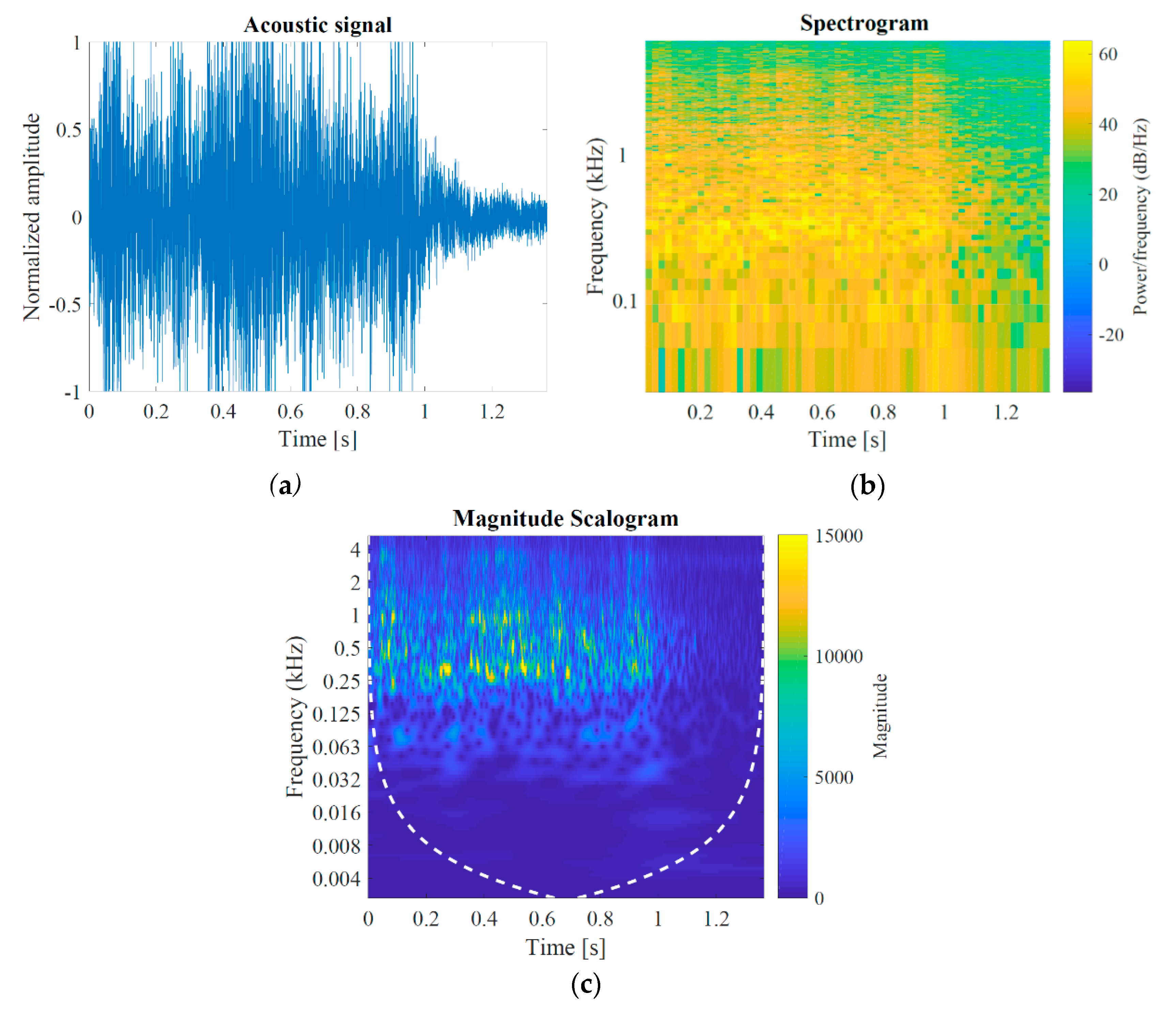
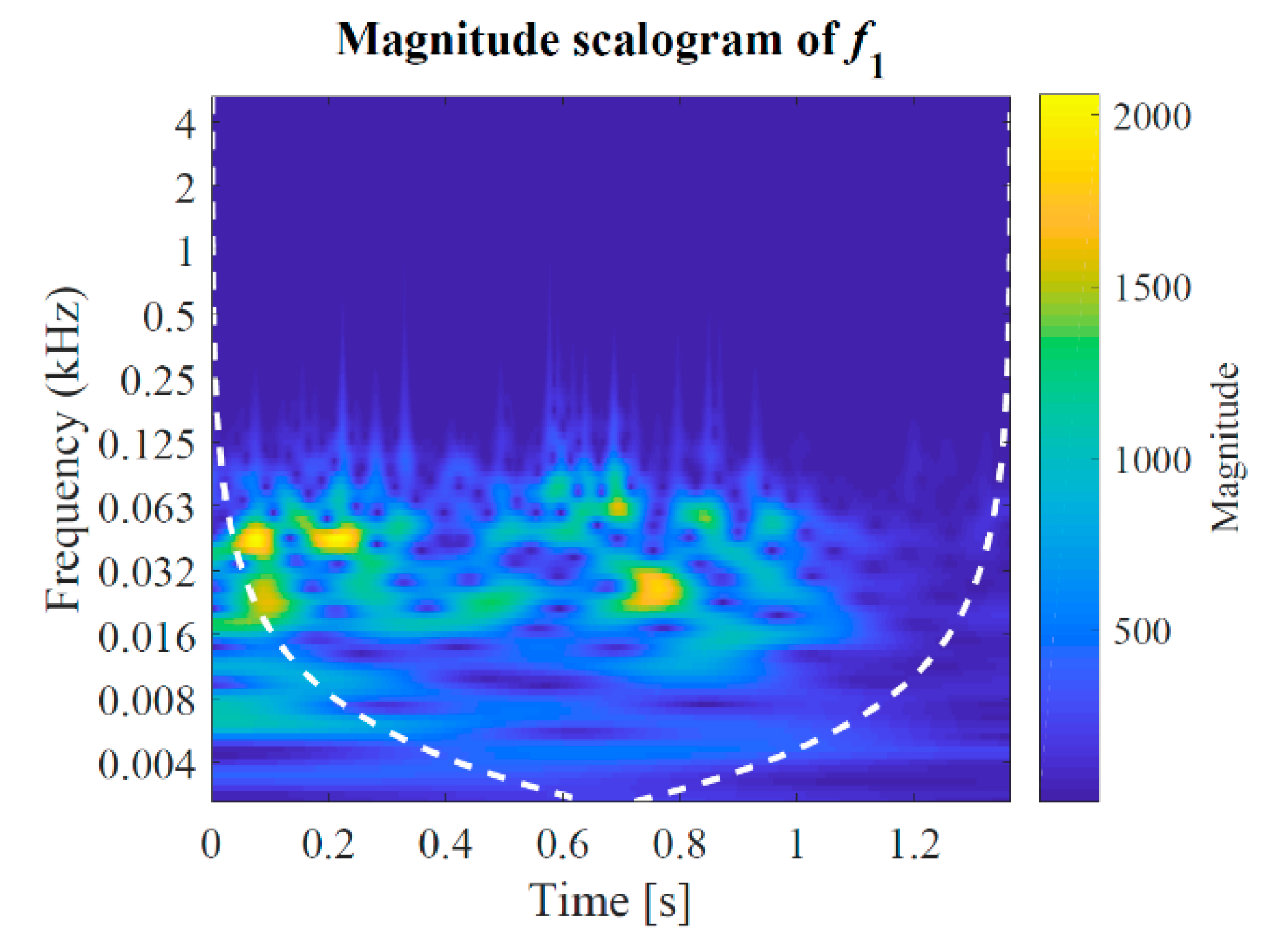
Swirl combustion is characterized by narrow-band frequencies at a few hundred Hz; however, high-frequency components can be located in a wider band. Therefore, Wavelet transform is an excellent tool to evaluate the temporal signal, as it is a multi-scale technique, properly fitting to the acoustic signal of a flame;
2.
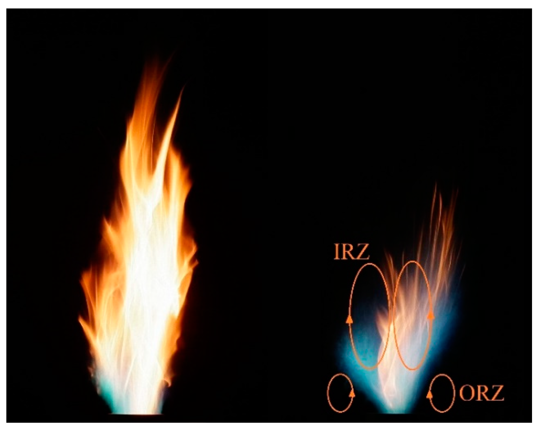
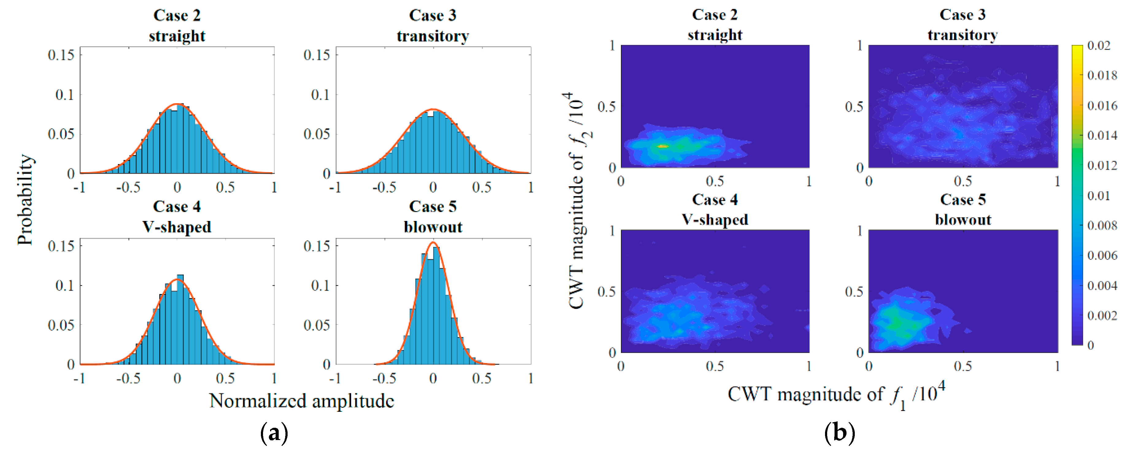
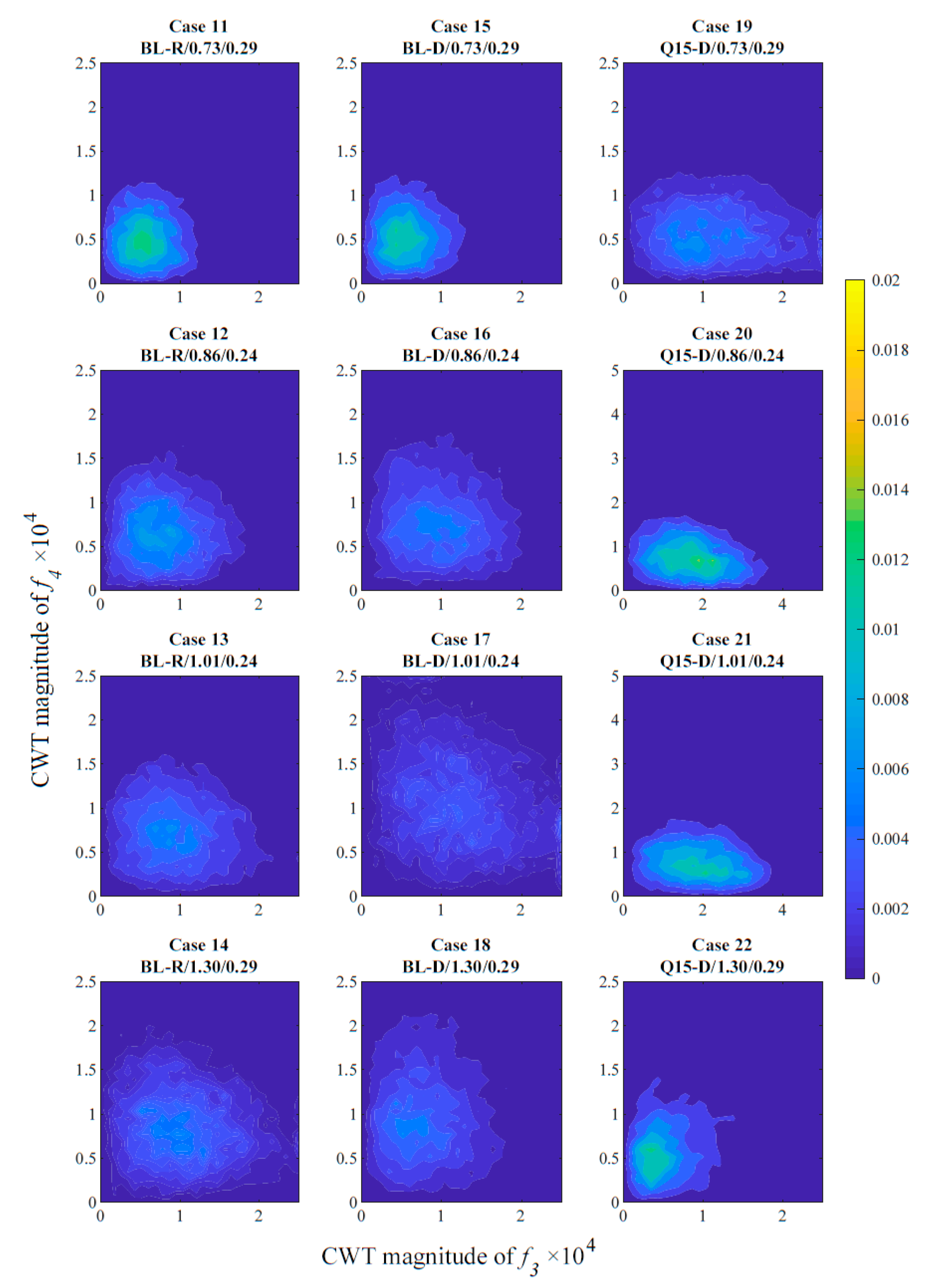
Frequencies of f1 = 230 Hz, f2 = 500 Hz, f3 = 1600 Hz, f4 = 3200 Hz were found to dominate the investigated spectra. The joint histogram of the wavelet coefficients and single histogram of the pressure signal was evaluated as the spectrum showed stochastic magnitude variation. Stable V-shaped flames, which were observed only in the case of diesel oil combustion, were governed by f1 and f2, while the characteristic frequencies of straight flames were f3 and f4. Flame blowout was accompanied by decreasing amplitudes of both pressure fluctuations and wavelet coefficients;
3.
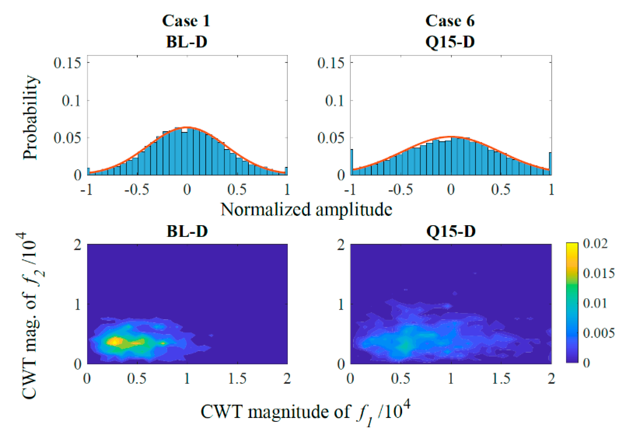
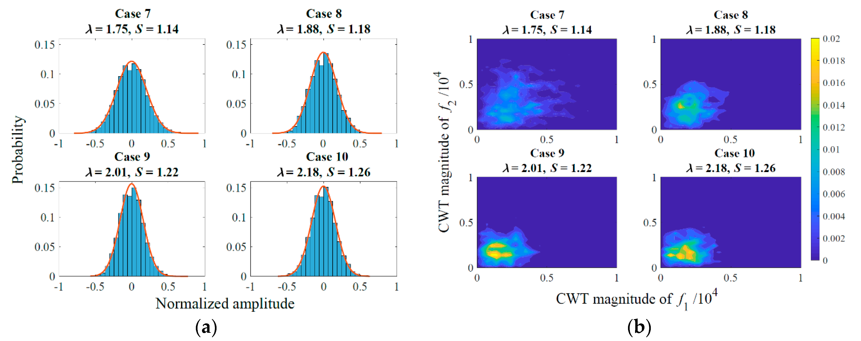
Combustion of rapeseed oil and diesel oil were found to be similar from an acoustic point of view. The joint histogram of the governing frequencies showed identical shape. However, flame acoustics differed notably when a 15° quarl was put on the burner lip, indicating that the analysis is highly sensitive to the burner geometry;
4.
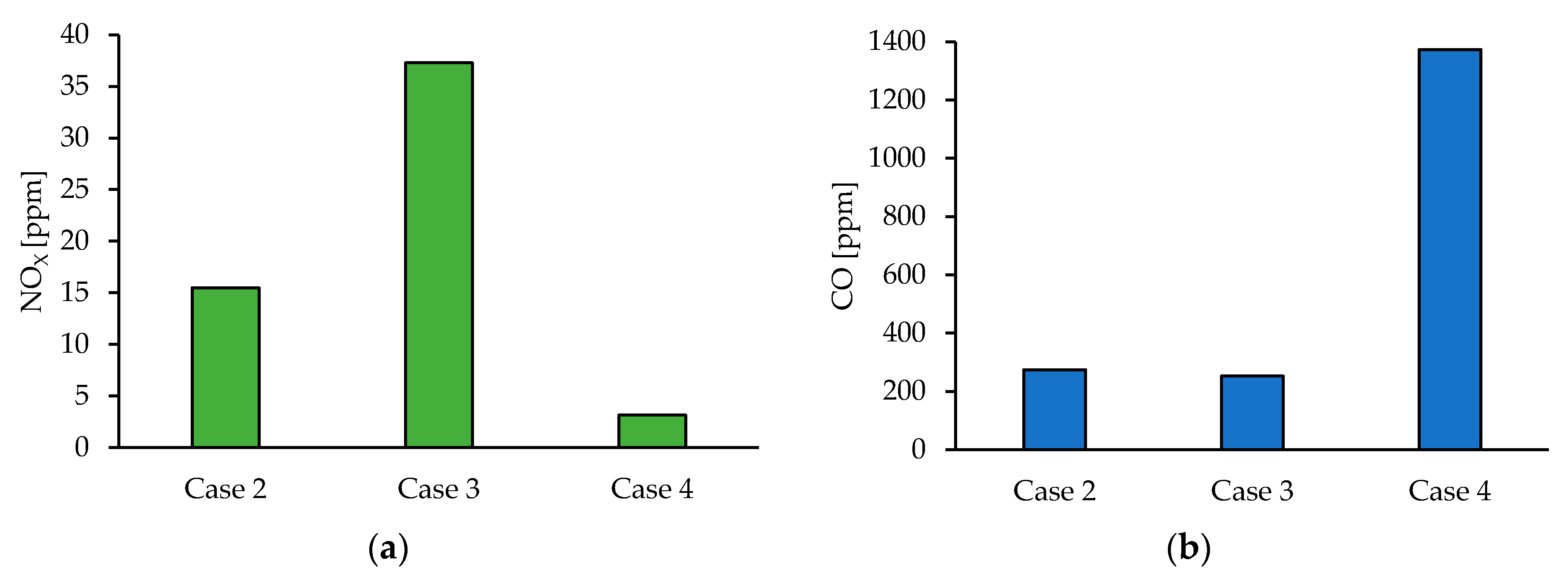
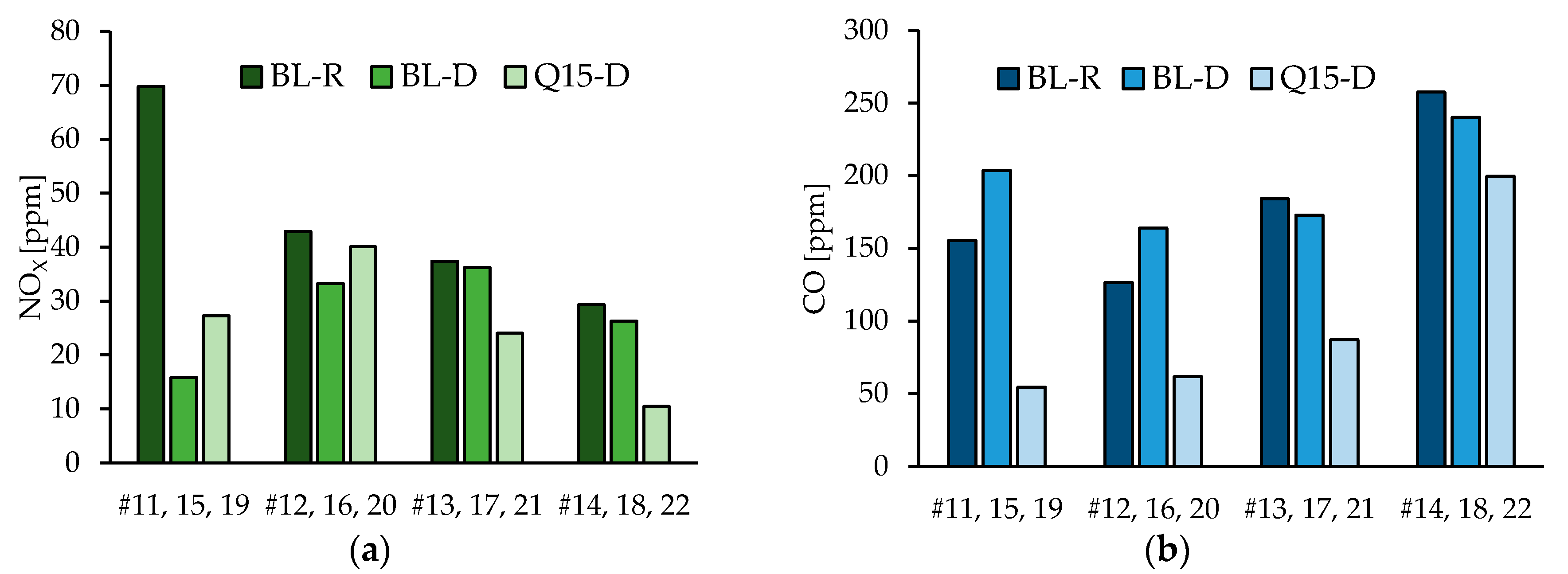
Pollutant emission of rapeseed oil combustion slightly exceeded that of diesel oil combustion. The quarl affected the pollutant emissions favorably in the case of diesel oil combustion since the rapeseed oil flame was blown out with a quarl. Rapeseed oil combustion might result in high NOX emission when the droplet size is small due to the possibility of crust formation, hence hindering the evaporation process.
The conclusions of the present research can be directly used in steady-operating applications such as boilers, furnaces, and gas turbines, especially in rural areas where crude vegetable or other waste oils might be an economically favorable energy source. There are several opportunities for future research since the combustion of HRF types might require special attention. Lowering the viscosity through preheating is a traditional method; however, crust formation might only be relevant above a certain droplet size. Determining this limitation would facilitate the spreading of the utilization of various HRFs. Wavelet transform was proven to be a powerful tool to filter the acoustic signal to analyze the flame behavior, which might be useful for predicting flame blowout for HRF combustion. Pollutant emission of simple burners can be optimized by, e.g., using a properly designed quarl. Such a feature might offer a reduced NOX and CO emission. All the measurement data and evaluation Matlab code will be available upon request.

Funding

This paper was supported by the National Research, Development and Innovation Fund of Hungary, project No. OTKA-FK 124704, BME NC TKP2020 Thematic Excellence Program, and the János Bolyai Research Scholarship of the Hungarian Academy of Sciences.

Conflicts of Interest

The author declares no conflict of interest.

References

  1. Chen, H.-G.; Zhang, Y.-H.P. New biorefineries and sustainable agriculture: Increased food, biofuels, and ecosystem security. Renew. Sustain. Energy Rev. 2015, 47, 117–132. [Google Scholar] [CrossRef]
  2. IEA. Installed Power Generation Capacity by Source in the Stated Policies Scenario, 2000–2040. Available online: https://www.iea.org/data-and-statistics/charts/installed-power-generation-capacity-by-source-in-the-stated-policies-scenario-2000-2040 (accessed on 1 May 2020).
  3. IEA. Renewables. Available online: https://www.iea.org/reports/global-energy-review-2020/renewables (accessed on 20 June 2020).
  4. Feuvre, P.L. Are Aviation Biofuels Ready for Take off? Available online: https://www.iea.org/commentaries/are-aviation-biofuels-ready-for-take-off (accessed on 20 June 2020).
  5. Mandolesi De Araújo, C.D.; De Andrade, C.C.; e Silva, E.D.S.; Dupas, F.A. Biodiesel production from used cooking oil: A review. Renew. Sustain. Energy Rev. 2013, 27, 445–452. [Google Scholar] [CrossRef]
  6. Adeniyi, O.M.; Azimov, U.; Burluka, A. Algae biofuel: Current status and future applications. Renew. Sustain. Energy Rev. 2018, 90, 316–335. [Google Scholar] [CrossRef]
  7. Brynolf, S.; Taljegard, M.; Grahn, M.; Hansson, J. Electrofuels for the transport sector: A review of production costs. Renew. Sustain. Energy Rev. 2018, 81, 1887–1905. [Google Scholar] [CrossRef]
  8. Channiwala, S.A.; Parikh, P.P. A unified correlation for estimating HHV of solid, liquid and gaseous fuels. Fuel 2002, 81, 1051–1063. [Google Scholar] [CrossRef]
  9. Chiong, M.C.; Chong, C.T.; Ng, J.H.; Lam, S.S.; Tran, M.V.; Chong, W.W.F.; Mohd Jaafar, M.N.; Valera-Medina, A. Liquid biofuels production and emissions performance in gas turbines: A review. Energy Convers. Manag. 2018, 173, 640–658. [Google Scholar] [CrossRef] [Green Version]
  10. Liu, S.; Chen, W.; Zhu, Z.; Jiang, S.; Ren, T.; Guo, H. A review of the developed new model biodiesels and their effects on engine combustion and emissions. Appl. Sci. 2018, 8, 2303. [Google Scholar] [CrossRef] [Green Version]
  11. Siwale, L.; Kristóf, L.; Adam, T.; Bereczky, A.; Mbarawa, M.; Penninger, A.; Kolesnikov, A. Combustion and emission characteristics of n-butanol/diesel fuel blend in a turbo-charged compression ignition engine. Fuel 2013, 107, 409–418. [Google Scholar] [CrossRef]
  12. Kim, H.Y.; Ge, J.C.; Choi, N.J. Effects of Ethanol—Diesel on the Combustion and Emissions from a Diesel Engine at a Low Idle Speed. Appl. Sci. 2020, 10, 4153. [Google Scholar] [CrossRef]
  13. Toldrá-Reig, F.; Mora, L.; Toldrá, F. Trends in biodiesel production from animal fatwaste. Appl. Sci. 2020, 10, 3644. [Google Scholar] [CrossRef]
  14. Seljak, T.; Buffi, M.; Valera-Medina, A.; Chong, C.T.; Chiaramonti, D.; Katrašnik, T. Bioliquids and their use in power generation—A technology review. Renew. Sustain. Energy Rev. 2020, 129, 109930. [Google Scholar] [CrossRef]
  15. Mahfouz, A.; Moneib, H.A.; El-fatih, A.; El-Sherif, A.F.; Ayoub, H.S.; Emara, A. Comparative study among waste cooking oil blends flame spectroscopy as an alternative fuel through using an industrial burner. Renew. Energy 2020, 159, 893–907. [Google Scholar] [CrossRef]
  16. Lehto, J.; Oasmaa, A.; Solantausta, Y.; Kytö, M.; Chiaramonti, D. Review of fuel oil quality and combustion of fast pyrolysis bio-oils from lignocellulosic biomass. Appl. Energy 2014, 116, 178–190. [Google Scholar] [CrossRef]
  17. Prussi, M.; Chiaramonti, D.; Riccio, G.; Martelli, F.; Pari, L. Straight vegetable oil use in Micro-Gas Turbines: System adaptation and testing. Appl. Energy 2012, 89, 287–295. [Google Scholar] [CrossRef]
  18. Buffi, M.; Seljak, T.; Cappelletti, A.; Bettucci, L.; Valera-Medina, A.; Katrašnik, T.; Chiaramonti, D. Performance and emissions of liquefied wood as fuel for a small scale gas turbine. Appl. Energy 2018, 230, 1193–1204. [Google Scholar] [CrossRef]
  19. Nevrlý, V.; Šomplák, R.; Putna, O.; Pavlas, M. Location of mixed municipal waste treatment facilities: Cost of reducing greenhouse gas emissions. J. Clean. Prod. 2019, 239, 118003. [Google Scholar] [CrossRef]
  20. Buffi, M.; Cappelletti, A.; Seljak, T.; Katrašnik, T.; Valera-Medina, A.; Chiaramonti, D. Emissions and Combustion Performance of a Micro Gas Turbine Powered with Liquefied Wood and its Blends. In Proceedings of the 9th International Conference on Applied Energy, Cardiff, UK, 21–24 August 2017; Volume 142, pp. 297–302. [Google Scholar]
  21. Kaushik, L.K.; Muthukumar, P. Thermal and economic performance assessments of waste cooking oil /kerosene blend operated pressure cook-stove with porous radiant burner. Energy 2020, 206, 118102. [Google Scholar] [CrossRef]
  22. Akinyemi, O.S.; Jiang, L. Development and combustion characterization of a novel twin-fluid fuel injector in a swirl-stabilized gas turbine burner operating on straight vegetable oil. Exp. Therm. Fluid Sci. 2019, 102, 279–290. [Google Scholar] [CrossRef]
  23. Akinyemi, O.S.; Jiang, L.; Hernandez, R.; McIntyre, C.; Holmes, W. Combustion of straight algae oil in a swirl-stabilized burner using a novel twin-fluid injector. Fuel 2019, 241, 176–187. [Google Scholar] [CrossRef]
  24. Murugan, S.; Ramaswamy, M.C.; Nagarajan, G. Performance, emission and combustion studies of a DI diesel engine using Distilled Tyre pyrolysis oil-diesel blends. Fuel Process. Technol. 2008, 89, 152–159. [Google Scholar] [CrossRef]
  25. Park, H.Y.; Han, K.; Kim, H.H.; Park, S.; Jang, J.; Yu, G.S.; Ko, J.H. Comparisons of combustion characteristics between bioliquid and heavy fuel oil combustion in a 0.7 MWth pilot furnace and a 75 MWe utility boiler. Energy 2020, 192, 116557. [Google Scholar] [CrossRef]
  26. Faeth, G.M.; Hsiang, L.P.; Wu, P.K. Structure and breakup properties of sprays. Int. J. Multiph. Flow 1995, 21, 99–127. [Google Scholar] [CrossRef]
  27. Dryer, F.L. Water addition to practical combustion systems—Concepts and applications. Symp. Combust. 1977, 16, 279–295. [Google Scholar] [CrossRef]
  28. de Jager, B.; Kok, J.B.W.; Skevis, G. The effects of water addition on pollutant formation from LPP gas turbine combustors. Proc. Combust. Inst. 2007, 31, 3123–3130. [Google Scholar] [CrossRef]
  29. Seljak, T.; Pavalec, K.; Buffi, M.; Valera-Medina, A.; Katrasnik, T.; Chiaramonti, D. Challenges and Solutions for Utilization of Bioliquids in Microturbines. J. Eng. Gas Turbines Power 2019, 141, 031401. [Google Scholar] [CrossRef] [Green Version]
  30. Kun-Balog, A.; Sztankó, K. Reduction of pollutant emissions from a rapeseed oil fired micro gas turbine burner. Fuel Process. Technol. 2015, 134, 352–359. [Google Scholar] [CrossRef]
  31. Urbán, A.; Malý, M.; Józsa, V.; Jedelský, J. Effect of liquid preheating on high-velocity airblast atomization: From water to crude rapeseed oil. Exp. Therm. Fluid Sci. 2019, 102, 137–151. [Google Scholar] [CrossRef]
  32. Hsuan, C.Y.; Hou, S.S.; Wang, Y.L.; Lin, T.H. Water-In-Oil emulsion as boiler fuel for Reduced NOx emissions and improved energy saving. Energies 2019, 12, 1002. [Google Scholar] [CrossRef] [Green Version]
  33. Yang, D.; Xia, Z.; Huang, L.; Ma, L.; Feng, Y.; Xiao, Y. Exprimental study on the evaporation characteristics of the kerosene gel droplet. Exp. Therm. Fluid Sci. 2018, 93, 171–177. [Google Scholar] [CrossRef]
  34. Khateeb, A.A.; Elbaz, A.M.; Guida, P.; Roberts, W.L. Influence of Asphaltene Concentration on the Combustion of a Heavy Fuel Oil Droplet. Energy Fuels 2018, 32, 12981–12991. [Google Scholar] [CrossRef] [Green Version]
  35. Elbaz, A.M.; Khateeb, A.A.; Roberts, W.L. PM from the combustion of heavy fuel oils. Energy 2018, 152, 455–465. [Google Scholar] [CrossRef] [Green Version]
  36. Józsa, V.; Csemány, D. Evaporation of renewable fuels in a lean premixed prevaporized burner. Period. Polytech. Mech. Eng. 2016, 60, 82–88. [Google Scholar] [CrossRef] [Green Version]
  37. Lefebvre, A.H.; Ballal, D.R. Gas Turbine Combustion, 3rd ed.; CRC Press: Boca Raton, FL, USA, 2010; ISBN 9781420086058. [Google Scholar]
  38. Correa, S.M. A Review of NOx Formation Under Gas-Turbine Combustion Conditions. Combust. Sci. Technol. 1993, 87, 329–362. [Google Scholar] [CrossRef]
  39. Noiray, N.; Denisov, A. A method to identify thermoacoustic growth rates in combustion chambers from dynamic pressure time series. Proc. Combust. Inst. 2017, 36, 3843–3850. [Google Scholar] [CrossRef]
  40. Glassman, I.; Yetter, R. Combustion, 4th ed.; Academic Press: Burlington, VT, USA, 2008; ISBN 978-0-12-088573-2. [Google Scholar]
  41. Józsa, V.; Kun-Balog, A. Stability and emission analysis of crude rapeseed oil combustion. Fuel Process. Technol. 2017, 156, 204–210. [Google Scholar] [CrossRef]
  42. Singh, A.V.; Yu, M.; Gupta, A.K.; Bryden, K.M. Thermo-acoustic behavior of a swirl stabilized diffusion flame with heterogeneous sensors. Appl. Energy 2013, 106, 1–16. [Google Scholar] [CrossRef]
  43. Khalil, A.E.E.; Gupta, A.K. Acoustic and heat release signatures for swirl assisted distributed combustion. Appl. Energy 2017, 193, 125–138. [Google Scholar] [CrossRef] [Green Version]
  44. Candel, S.; Durox, D.; Schuller, T.; Bourgouin, J.-F.; Moeck, J.P. Dynamics of Swirling Flames. Annu. Rev. Fluid Mech. 2014, 46, 147–173. [Google Scholar] [CrossRef]
  45. Gotoda, H.; Hayashi, K.; Tsujimoto, R.; Domen, S.; Tachibana, S. Dynamical Properties of Combustion Instability in a Laboratory-Scale Gas-Turbine Model Combustor. J. Eng. Gas Turbines Power 2016, 139, 041509. [Google Scholar] [CrossRef]
  46. Novotni, G.I.; Józsa, V. Sound Pressure Level Analysis of a Liquid-Fueled Lean Premixed Swirl Burner with Various Quarls. Acoustics 2020, 2, 10. [Google Scholar] [CrossRef] [Green Version]
  47. Chui, C.K. An Introduction to Wavelets, 1st ed.; Academic Press: San Diego, CA, USA, 1992; ISBN 9780121745844. [Google Scholar]
  48. Nair, S.; Lieuwen, T. Acoustic Detection of Blowout in Premixed Flames. J. Propuls. Power 2005, 21, 32–39. [Google Scholar] [CrossRef]
  49. Chaudhuri, S.; Cetegen, B.M. Blowoff characteristics of bluff-body stabilized conical premixed flames with upstream spatial mixture gradients and velocity oscillations. Combust. Flame 2008, 153, 616–633. [Google Scholar] [CrossRef]
  50. Dey, D.; Chaudhari, R.R.; Mukhopadhyay, A.; Sen, S.; Chakravorti, S. A cross-wavelet transform aided rule based approach for early prediction of lean blow-out in swirl-stabilized dump combustor. Int. J. Spray Combust. Dyn. 2015, 7, 69–89. [Google Scholar] [CrossRef]
  51. Idahosa, U.; Basu, S.; Miglani, A. System Level Analysis of Acoustically Forced Nonpremixed Swirling Flames. J. Therm. Sci. Eng. Appl. 2014, 6, 031015. [Google Scholar] [CrossRef]
  52. Józsa, V.; Kun-Balog, A. Effect of quarls on the blowout stability and emission of pollutants of a liquid-fueled swirl burner. J. Eng. Gas Turbines Power 2018, 140, 111502. [Google Scholar] [CrossRef]
  53. Broumand, M.; Albert-Green, S.; Yun, S.; Hong, Z.; Thomson, M.J. Spray combustion of fast pyrolysis bio-oils: Applications, challenges, and potential solutions. Prog. Energy Combust. Sci. 2020, 79, 100834. [Google Scholar] [CrossRef]
  54. Beér, J.M.; Chigier, N.A. Combustion Aerodynamics; Robert, E., Ed.; Krieger Publishing Company, Inc.: London, UK, 1972. [Google Scholar]
  55. Stöhr, M.; Boxx, I.; Carter, C.; Meier, W. Dynamics of lean blowout of a swirl-stabilized flame in a gas turbine model combustor. Proc. Combust. Inst. 2011, 33, 2953–2960. [Google Scholar] [CrossRef] [Green Version]
  56. Lefebvre, A.H.; McDonell, V.G. Atomization and Sprays, 2nd ed.; CRC Press: Boca Raton, FL, USA, 2017; ISBN 978-1-4987-3625-1. [Google Scholar]
  57. Addison, P.S. The Illustrated Wavelet Transform Handbook; IOP Publishing Ltd.: Edinburgh, UK, 2002; ISBN 0750306920. [Google Scholar]
  58. Huang, Y.; Yang, V. Dynamics and stability of lean-premixed swirl-stabilized combustion. Prog. Energy Combust. Sci. 2009, 35, 293–364. [Google Scholar] [CrossRef]
  59. Reed, R.J. North American Combustion Handbook, 3rd ed.; North American Mfg. Co.: Cleveland, OH, USA, 1997; ISBN 9780960159635. [Google Scholar]
  60. Idahosa, U.; Saha, A.; Xu, C.; Basu, S. Non-premixed acoustically perturbed swirling flame dynamics. Combust. Flame 2010, 157, 1800–1814. [Google Scholar] [CrossRef]
  61. Komarek, T.; Polifke, W. Impact of Swirl Fluctuations on the Flame Response of a Perfectly Premixed Swirl Burner. J. Eng. Gas Turbines Power 2010, 132, 061503. [Google Scholar] [CrossRef]
  62. Zhou, H.; Huang, Y.; Meng, S. Response of non-premixed swirl-stabilized flames to acoustic excitation and jet in cross-flow perturbations. Exp. Therm. Fluid Sci. 2017, 82, 124–135. [Google Scholar] [CrossRef]
  63. Gotoda, H.; Kobayashi, H.; Hayashi, K. Chaotic dynamics of a swirling flame front instability generated by a change in gravitational orientation. Phys. Rev. E 2017, 95, 022201. [Google Scholar] [CrossRef] [PubMed]
  64. Hayashi, Y.; Funatsu, M.; Kobayashi, H.; Gotoda, H. Nonlinear analysis on dynamical motion of combustion instability in a laboratory-scale gas turbine model combustor. In Proceedings of the 8th European Combustion Meeting, Dubrovnik, Croatia, 18–21 April 2017; pp. 2505–2507. [Google Scholar]
  65. Kabiraj, L.; Sujith, R.I. Nonlinear self-excited thermoacoustic oscillations: Intermittency and flame blowout. J. Fluid Mech. 2012, 713, 376–397. [Google Scholar] [CrossRef]
  66. Oberleithner, K.; Stöhr, M.; Im, S.H.H.; Paschereit, C.O.; St, M.; Im, S.H.H.; Paschereit, C.O. Linear stability analysis of turbulent swirling combustor flows: Impact of flow field and flame shapes on the PVC. In Proceedings of the European Combustion Meeting—2015, Budapest, Hungary, 30 March–2 April 2015. [Google Scholar]
  67. Ebi, D.; Denisov, A.; Bonciolini, G.; Boujo, E.; Noiray, N.; Denisov, A.; Bonciolini, G.; Noiray, N.; Ebi, D.; Denisov, A.; et al. Flame dynamics intermittency in the bi-stable region near a subcritical hopf bifurcation. In Turbo Expo: Power for Land, Sea, and Air, Proceedings of the Turbomachinery Technical Conference and Exposition; American Society of Mechanical Engineers: Charlotte, NC, USA, 26–30 June 2017; ISBN 978-0-7918-5085-5. [Google Scholar]
  68. Hadef, R.; Merkle, K.; Lenze, B.; Leuckel, W. An experimental study of airblast atomizer spray flames. J. Inst. Energy 2000, 73, 50–55. [Google Scholar]
Figure 1. The combustion test rig.
Applsci 10 04907 g001
Figure 2. The investigated burner and the used quarl.
Applsci 10 04907 g002
Figure 3. Straight flame state near the end of the transitory regime (left, pg = 0.3 bar, λ = 1.1, and S’ = 0.82) and V-shaped flame (right, pg = 0.3 bar, λ = 1.23, and S’ = 0.91) of BL-D [46].
Applsci 10 04907 g003
Figure 4. (a) Raw acoustic signal at blowout of Case 1. (b) Spectrogram of the signal at 29 window size and 50% overlapping. (c) Magnitude scalogram of the signal by using a Morse wavelet.
Applsci 10 04907 g004
Figure 5. CWT (continuous wavelet transform) of the CWT coefficients at f1 = 230 Hz.
Applsci 10 04907 g005
Figure 6. (a) Histograms of the pressure signal at characteristic flame shapes. (b) Joint histograms of CWT coefficients at f1 and f2 of Cases 2–5.
Applsci 10 04907 g006
Figure 7. Histogram of the pressure signal (top) and joint histogram of CWT coefficients of f1 and f2 (bottom) of Cases 1 and 6.
Applsci 10 04907 g007
Figure 8. Combustion in V-shaped mode until blowout at pg = 0.3 bar and Q15-D: Cases 7–10. (a) Histograms of the pressure signal and (b) joint histograms of the CWT coefficients at f1 and f2 (bottom).
Applsci 10 04907 g008
Figure 9. Comparison of BL-R (left, Cases 11–14), BL-D (middle, Cases 15–18), and Q15-D (right, Cases 19–22) at the same conditions at each row. The first number after the setup name notes λ, which is followed by S. The points picked at similar S values in the weak swirl regime. Note the doubled axis limits in Cases 20 and 21.
Applsci 10 04907 g009
Figure 10. (a) NOX and (b) CO emissions of Cases 2–4, shown Figure 6.
Applsci 10 04907 g010
Figure 11. (a) NOX and (b) CO emissions of Cases 11–22, shown Figure 9.
Applsci 10 04907 g011
Table 1. Literature survey of heavy renewable fuels (HRF) utilization.
Fuel (Blends)PlatformKey FindingsReferences
waste cooking oil (WCO) and dieselindustrial burnerNeat WCO combustion is unstable. 20% WCO + 80% diesel oil blend provides a stable flame.[15]
pyrolysis bio-oilsindustrial burnerPyrolysis bio-oil combustion is possible with low emissions; however, a system upgrade is required.[16]
sunflower oil (SFO) and dieselmicro gas turbine15% and 30% SFO–diesel oil blends provided smooth operation with increased CO and NOX emissions.[17]
liquefied wood and ethanolmicro gas turbineStable combustion and energy generation is possible, but CO and unburnt fuel emission is excessive.[18,20]
WCO and kerosenestove burnerStable combustion up to the investigated 50% blend; however, CO and NOX emissions slightly increase.[21]
soybean and algae oilsatmospheric burnerA novel atomizer design allowed stable operation and low emission without fuel preheating.[22,23]
tire pyrolysis oil (TPO) and dieseldiesel engineNeat TPO leads to unstable combustion. Blends show lower NOX and higher CO and HC emission.[24]
C-heavy oil and crude jatropha oil (CJO)utility boilerNote that CJO is lighter fuel than C-heavy oil. NOX emission and wall heat flux were both decreased in the case of a 79 MW utility boiler.[25]
Table 2. List of the investigated cases and their properties.
Case No.pg [Bar]S [–]λ [–]FuelGeometry
Case 10.60.791.51DBL
Case 20.30.390.70DBL
Case 30.30.681.1DBL
Case 40.30.811.34DBL
Case 50.30.951.75DBL
Case 60.60.791.51DQ15
Case 70.30.951.75DQ15
Case 80.30.981.88DQ15
Case 90.31.012.01DQ15
Case 100.31.042.18DQ15
Case 110.450.290.73RBL
Case 120.80.240.86RBL
Case 131.10.241.01RBL
Case 141.60.291.30RBL
Case 150.450.290.73DBL
Case 160.80.240.86DBL
Case 171.10.241.01DBL
Case 181.60.291.30DBL
Case 190.450.290.73DQ15
Case 200.80.240.86DQ15
Case 211.10.241.01DQ15
Case 221.60.291.30DQ15
Table 3. Fuel properties of diesel oil at 25 °C and crude rapeseed oil at 150 °C [31,41].
PropertyDiesel OilCrude Rapeseed Oil
Thermal power [kW]1515
Lower Heating Value [MJ/kg]4337
Fuel flow rate [g/s]0.350.4
Dynamic viscosity [mPa s]3.453.28 (40.7 at 25 °C)
Density [kg/m3]830833 (920 at 25 °C)
Surface tension [mN/m]2824
Table 4. Estimated properties of diesel oil atomization at various pg.
pg [Bar]SMD [µm]We [–]AFR [–]
0.327.17790.778
0.4522.011210.948
0.619.314381.09
0.817.118301.25
1.115.123631.45
1.613.331431.73
Table 5. Estimated properties of crude rapeseed oil atomization at various pg.
pg [Bar]SMD [µm]We [–]AFR [–]
0.322.89080.681
0.4518.013070.829
0.615.516780.953
0.813.521351.09
1.111.727571.27
1.610.136661.51

