Studies of Buried Layers and Interfaces of Tungsten Carbide Coatings on the MWCNT Surface by XPS and NEXAFS Spectroscopy

 , ,
, ,  , , and
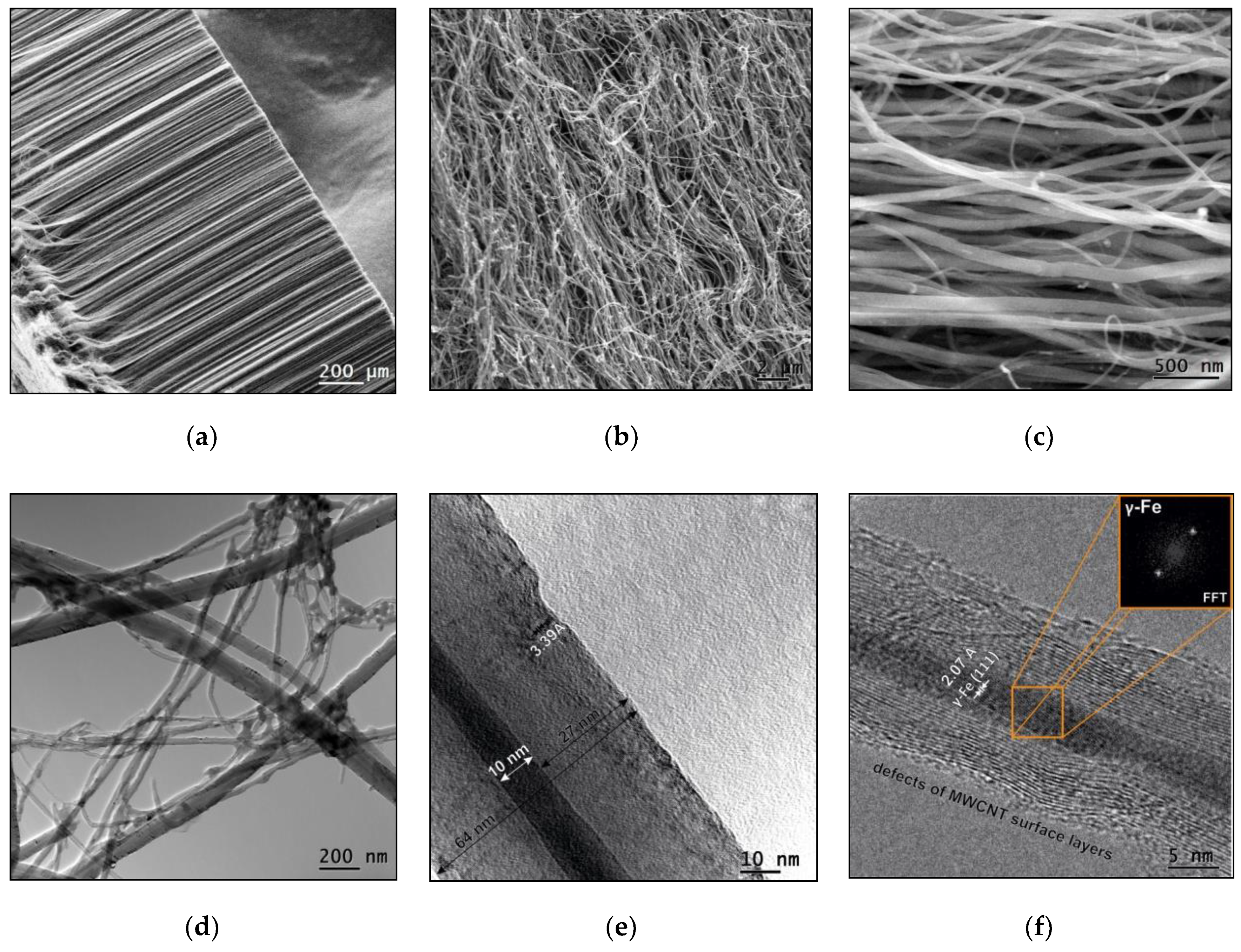
Abstract
1. Introduction
2. Materials and Methods
2.1. Materials
2.2. Experimental Details
2.2.1. Synthesis of MWCNTs
2.2.2. Synthesis of (Pyrolytic WC)/MWCNT Nanocomposites
2.3. Characterization
3. Results and Discussion
3.1. Initial MWCNT Research
3.2. (Pyrolytic WC)/MWCNT Nanocomposite Research
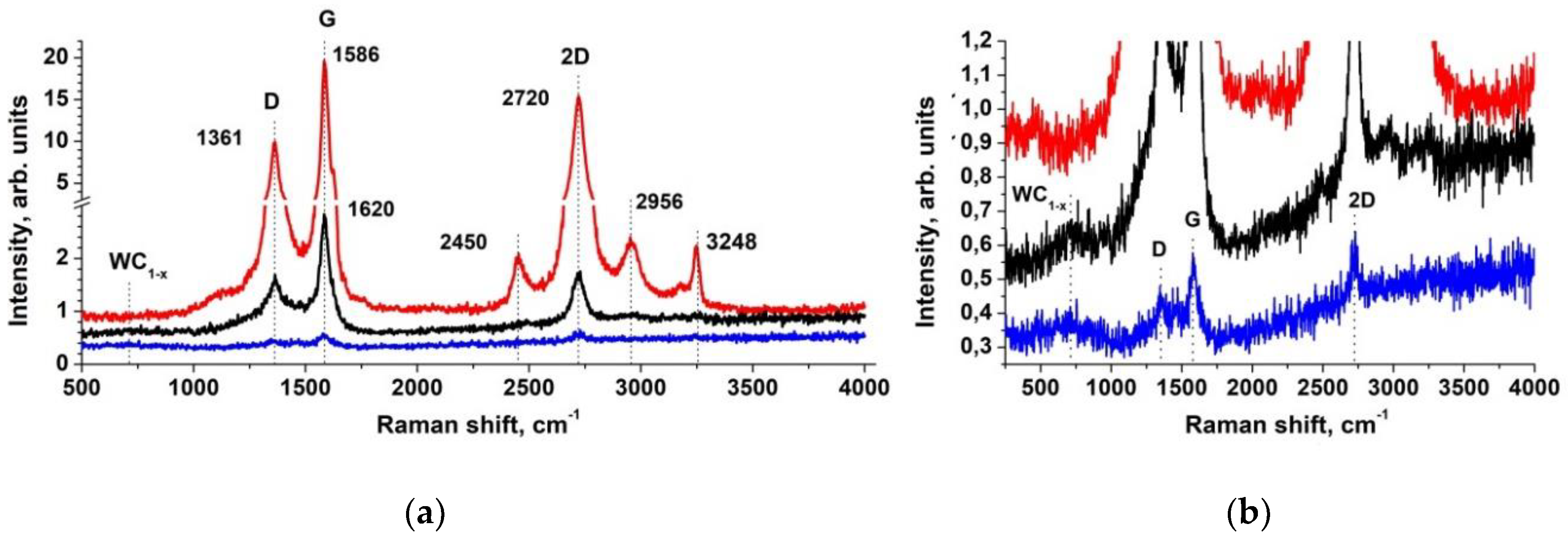
3.3. Raman Spectra of the Nanocomposites and Initial MWCNTs
3.4. NEXAFS Spectroscopy Research of the Nanocomposites and Initial MWCNTs
3.5. XPS Research of the Nanocomposites and Initial MWCNTs
4. Conclusions
Supplementary Materials
Author Contributions
Funding
Acknowledgments
Conflicts of Interest
References
- Siegbahn, K.; Nordling, C.; Fahlman, A.; Hamrin, K.; Hedman, J.; Nordberg, R.; Johansson, C.; Bergmark, T.; Karlsson, S.-E.; Lindgren, I.; et al. ESCA: Atomic, Molecular and Solid-State Structure Studied by Means of Electron Spectroscopy, 3rd ed.; Almqvist and Wiksells: Uppsala, Sweden, 1967. [Google Scholar]
- Siegbahn, K.; Nordling, C.; Johansson, G.; Hedman, J.; Heden, P.-F.; Hamrin, K.; Gelius, U.; Bergmark, T.; Werme, L.O.; Manne, R.; et al. ESCA Applied to Free Molecules, 1st ed.; North-Holland: Amsterdam, The Netherlands, 1969. [Google Scholar]
- Brundle, C.R.; Baker, A.D. Electron Spectroscopy: Theory, Techniques and Applications (Volume 1); Academic Press: London, UK, 1977. [Google Scholar]
- Brundle, C.R.; Baker, A.D. Electron Spectroscopy: Theory, Techniques and Applications (Volumes 2–5); Academic Press: London, UK, 1978–1984. [Google Scholar]
- Briggs, D.; Seah, M.P. Practical Surface Analysis, Auger and X-ray Photoelectron Spectroscopy (Volume 1); John Wiley& Sons: Chichester, UK, 1990. [Google Scholar]
- Hufner, S. Photoelectron Spectroscopy, Principles and Applications; Springer: Berlin/Heidelberg, Germany, 1995. [Google Scholar]
- Smith, G.C. Quantitative Surface Analysis for Materials Science; The Institute of Metals: London, UK, 1991. [Google Scholar]
- Watts, J.F. X-ray Photoelectron Spectroscopy. Vacuum 1994, 45, 653–671. [Google Scholar] [CrossRef]
- Briggs, D.; Grant, J.T. Surface Analysis by Auger and X-Ray Photoelectron Spectroscopy; IM Publication: Chichester, England, 2003. [Google Scholar]
- Hufner, S.; Schmidt, S.; Reinert, F. Photoelectron Spectroscopy—An Overview. Nucl. Instrum. Methods Phys. Res. Sect. A 2005, 547, 8–23. [Google Scholar] [CrossRef]
- Fadley, C.S. X-ray photoelectron spectroscopy: Progress and perspectives. J. Electron. Spect. Relat. Phenom. 2010, 178–179, 2–32. [Google Scholar] [CrossRef]
- Hofmann, S. Auger- and X-Ray Photoelectron Spectroscopy in Materials Science; Springer: Berlin/Heidelberg, Germany, 2013. [Google Scholar]
- Greczynski, G.; Hultman, L. X-ray photoelectron spectroscopy: Towards reliable binding energy referencing. Prog. Mater. Sci. 2020, 107, 100591. [Google Scholar] [CrossRef]
- Seah, M.P.; Dench, W.A. Quantitative electron spectroscopy of surfaces: A standard data base for electron inelastic mean free paths in solids. Surf. Interface Anal. 1979, 1, 2–11. [Google Scholar] [CrossRef]
- Rao, C.N.R.; Cheetham, A.K. Science and technology of nanomaterials: Current status and future prospects. J. Mater. Chem. 2001, 11, 2887–2894. [Google Scholar] [CrossRef]
- Daoush, W.M.; Lim, B.K.; Mo, C.B.; Nam, D.H.; Hong, S.H. Electrical and mechanical properties of carbon nanotube reinforced copper nanocomposites fabricated by electroless deposition process. Mater. Sci. Eng. A 2009, 247, 513–514. [Google Scholar] [CrossRef]
- Eder, D. Carbon Nanotube-Inorganic Hybrids. Chem. Rev. 2010, 110, 1348–1385. [Google Scholar] [CrossRef]
- Ebbesen, T. Wetting, filling and decorating carbon nanotubes. J. Phys. Chem. Solids 1996, 57, 951–955. [Google Scholar] [CrossRef]
- Rakov, E.G. Chemistry of Carbon Nanotubes. In Nanomaterials Handbook; Golotsi, Y., Ed.; CRC Press: Boca Raton, FL, USA, 2006; Volume 56, pp. 105–175. [Google Scholar]
- Mu, S.C.; Tang, H.L.; Qian, S.H. Hydrogen storage in carbon nanotubes modified by microwave plasma etching and Pd decoration. Carbon 2006, 44, 762–767. [Google Scholar] [CrossRef]
- Gao, C.; Li, W.; Maekawa, T. Magnetic Carbon Nanotubes: Synthesis by Electrostatic Self-Assembly Approach and Application in Biomanipulations. J. Phys. Chem. B 2006, 110, 7213–7220. [Google Scholar] [CrossRef]
- Zhao, X.; Jiang, P.; Chu, W.; Mu, S.; Liu, D.; Song, L.; Liu, L.; Luo, S.; Zhang, Z.; Xiang, Y.; et al. The growth of carbon nanostructures in the channels of aligned carbon nanotube. Carbon 2006, 44, 1298–1352. [Google Scholar] [CrossRef]
- Tersoff, J. A barrier falls. Nature 2003, 424, 622–623. [Google Scholar] [CrossRef] [PubMed]
- Kadomtseva, A.V.; Vorotyntsev, A.V.; Vorotyntsev, V.M.; Petukhov, A.N.; Ob’edkov, A.M.; Kremlev, K.V.; Kaverin, B.S. Effect of the Catalytic System Based on Multi-Walled Carbon Nanotubes Modified with Copper Nanoparticles on the Kinetics of Catalytic Reduction of Germanium Tetrachloride by Hydrogen. Russ. J. Appl. Chem. 2015, 88, 595–602. [Google Scholar] [CrossRef]
- Sivkov, V.N.; Ob’edkov, A.M.; Petrova, O.V.; Nekipelov, S.V.; Mingaleva, A.E.; Kremlev, K.V.; Kaverin, B.S.; Semenov, N.M.; Kadomtseva, A.V.; Gusev, S.A.; et al. Synchrotron, X-Ray, and Electron Microscopic Studies of Catalyst Systems Based on Multi-walled Carbon Nanotubes Modified by Copper Nanoparticles. Phys. Solid State 2020, 62, 214–222. [Google Scholar] [CrossRef]
- Liu, Q.; Ren, W.; Chen, Z.-G.; Liu, B.; Yu, B.; Li, F.; Cong, H.; Cheng, H.-M. Direct synthesis of carbon nanotubes decorated with size-controllable Fe nanoparticles encapsulated by graphitic layers. Carbon 2008, 46, 1417–1423. [Google Scholar] [CrossRef]
- Fang, Z.Z.; Wang, X.; Ryu, T.; Hwang, K.S.; Sohn, H.Y. Synthesis, sintering, and mechanical properties of nanocrystalline cemented tungsten carbide—A rewiew. Int. J. Refract. Met. Hard. Mater. 2009, 27, 288–299. [Google Scholar] [CrossRef]
- Rees, E.J.; Essaki, K.; Brady, C.D.A.; Burstein, G.T. Hydrogen electrocatalysts from microwave-synthesized nanoparticlulate carbides. J. Power Sources. 2009, 188, 75–81. [Google Scholar] [CrossRef]
- Wang, R.; Tian, C.; Wang, L.; Wang, B.; Zhang, H.; Fu, H. In situ simultaneous synthesis of WC/graphitic carbon nanocomposite as a highly efficient catalyst support for DMFC. Chem. Commun. 2009, 21, 3104–3106. [Google Scholar] [CrossRef]
- Antolini, E.; Gonzalez, E.R. Tungsten-based materials for fuel cell applications. Appl. Catal. B Environ. 2010, 96, 245–266. [Google Scholar] [CrossRef]
- Kim, C.H.; Hur, Y.G.; Lee, S.H.; Lee, K.-Y. Hydrocracking of vacuum residue using nano-dispersed tungsten carbide catalyst. Fuel 2018, 233, 200–206. [Google Scholar] [CrossRef]
- Colton, R.J.; Huang, J.-T.J.; Rabalais, J.W. Electronic structure of tungsten carbide and its catalytic behavior. Chem. Phys. Lett. 1975, 34, 337–339. [Google Scholar] [CrossRef]
- Keller, N.; Pietruszka, B.; Keller, V. A new one-demensional tungsten carbide nanostructured material. Mater. Lett. 2006, 60, 1774–1777. [Google Scholar] [CrossRef]
- Shi, X.; Yang, H.; Sun, P.; Shao, G.; Duan, X.; Zhen, X. Synthesis of multi-walled carbon nanotube-tungsten carbide composites by the reduction and carbonization process. Carbon 2007, 45, 1735–1742. [Google Scholar] [CrossRef]
- Li, G.; Ma, C.; Tang, J.; Sheng, J. Preparation and electrocatalytic property of WC/carbon nanotube composite. Electrochim. Acta 2007, 52, 2018–2023. [Google Scholar] [CrossRef]
- Zhao, Z.; Fang, X.; Li, Y.; Wang, Y.; Shen, P.K.; Xie, F.; Zhang, X. The origin of the high performance of tungsten carbides/carbon nanotubes supported Pt catalysts for methanol electrooxidation. Electrochem. Commun. 2009, 11, 290–293. [Google Scholar] [CrossRef]
- Rahsepar, M.; Pakshir, M.; Nikolaev, P.; Safavi, A.; Palanisamy, K.; Kim, H. Tungsten carbide on directly grown multi-walled carbon nanotubes as a co-catalyst for methanol oxidation. Appl. Catal. B. Environ. 2012, 127, 265–272. [Google Scholar] [CrossRef]
- Wang, L.; Du, T.; Cheng, J.; Xie, X.; Yang, B.; Li, M. Enhanced activity of urea electrooxidation on nickel catalysts supported on tungsten carbide/carbon nanotubes. J. Power Sources. 2015, 280, 550–554. [Google Scholar] [CrossRef]
- Kremlev, K.V.; Ob’edkov, A.M.; Semenov, N.M.; Kaverin, B.S.; Ketkov, S.Y.; Vilkov, I.V.; Andreev, P.V.; Gusev, S.A.; Aborkin, A.V. Synthesis of hybrid materials based on multi-walled carbon nanotubes decorated with WC1-x nanocoatigs of various morphologies. Tech. Phys. Lett. 2019, 45, 41–44. [Google Scholar] [CrossRef]
- Aborkin, A.V.; Saikov, I.V.; Berbentsev, V.D.; Ob’edkov, A.M.; Sytschev, A.E.; Alymov, M.I. The Use of Gas Extrusion for the Synthesis of a High-Strength Composite Based on a 5xxx Series Aluminum Alloy Strengthened with Carbon Nanostructures. Tech. Phys. Lett. 2020, 46, 207–210. [Google Scholar] [CrossRef]
- Sivkov, V.N.; Lomov, A.A.; Vasil’ev, A.L.; Nekipelov, S.V.; Petrova, O.V. X-Ray and Synchrotron Studies of Porous Silicon. Semiconductors 2013, 47, 1051–1057. [Google Scholar] [CrossRef]
- Sivkov, D.; Petrova, O.; Mingaleva, A.; Ob’edkov, A.; Kaverin, B.; Gusev, S.; Vilkov, I.; Isaenko, S.; Bogachuk, D.; Skandakov, R.; et al. The Structure and Chemical Composition of the Cr and Fe Pyrolytic Coatings on the MWCNTs Surface According to NEXAFS and XPS Spectroscopy. Nanomaterials 2020, 10, 374. [Google Scholar] [CrossRef] [PubMed]
- Obiedkov, A.M.; Kaverin, B.S.; Egorov, V.A.; Semenov, N.M.; Ketkov, S.Y.; Domrachev, G.A.; Kremlev, K.V.; Gusev, S.A.; Perevezentsev, V.N.; Moskvichev, A.N.; et al. Macroscopic cylinders on the basis of radial-oriented multi-wall carbon nanotubes. Lett. Mater. 2012, 2, 152–156. [Google Scholar] [CrossRef]
- Gorovikov, S.A.; Molodtsov, S.L.; Follath, R. Optical design of the high-energy resolution beamline at a dipole magnet of BESSY II. Nucl. Instrum. Methods Phys. Res. A 1998, 411, 506–512. [Google Scholar] [CrossRef]
- Fedoseenko, S.I.; Vyalikh, D.V.; Iossifov, I.F.; Follath, R.; Gorovikov, S.A.; Püttner, R.; Schmidt, J.S.; Molodtsov, S.L.; Adamchuk, V.K.; Gudat, W.; et al. Commissioning results and performance of the high-resolution Russian-German Beamline at BESSY II. Nucl. Instrum. Methods Phys. Res. A 2003, 505, 718–728. [Google Scholar] [CrossRef]
- Kim, J.; Jang, J.-H.; Lee, Y.-H.; Kwon, Y.-U. Enhancement of electrocatalytic activity of platinum for hydrogen oxidation reaction by sonochemically synthesized WC1-x nanoparticles. J. Power Sources. 2009, 193, 441–446. [Google Scholar] [CrossRef]
- Huang, W.; Wang, Y.; Luo, G.; Wei, F. 99.9% purity multi-walled carbon nanotubes by vacuum high-temperature annealing. Carbon 2003, 41, 2585–2590. [Google Scholar] [CrossRef]
- Sun, L.; Fouere, J.-C.; Sammet, T.; Hatzistergos, M.; Efstathiadis, H. Spectroscopic ellipsometry (SE) and grazing X-ray reflectometry (GXR) analyses on tungsten carbide films for diffusion barrier in copper metallization schemes. Thin Solid Film. 2004, 455–456, 519–524. [Google Scholar] [CrossRef]
- Gao, X.-H.; Wang, C.-B.; Guo, Z.-M.; Geng, Q.-F.; Theiss, W.; Liu, G. Structure, optical properties and thermal stability of Al2O3-WC nanocomposite ceramic spectrally selective solar absorbers. Opt. Mater. 2016, 58, 219–225. [Google Scholar] [CrossRef]
- Abad, M.D.; Sánchez-López, J.C.; Cusnir, N.; Sanjines, R. WC/a-C nanocomposite thin films: Optical and electrical properties. J. Appl. Phys. 2009, 105, 033510. [Google Scholar] [CrossRef]
- Hutchins, M.G.; Abu-Alkhair, O.; El-Nahass, M.M.; Abd El-Hady, K. Structural and optical characterization of thermally evaporated tungsten trioxide (WO3) thin films. Mater. Chem. Phys. 2006, 98, 401–405. [Google Scholar] [CrossRef]
- Kuzmin, A.; Purans, J.; Cazzanelli, E.; Vinegoni, C.; Mariotto, G. X-ray diffraction, extended x-ray absorption fine structure and Raman spectroscopy studies of WO3 powders and (1-x)WO3-y *xReO2 mixtures. J. Appl. Phys. 1998, 84, 5515. [Google Scholar] [CrossRef]
- Boulova, M.; Lucazeau, G. Crystallite Nanosize effect on the Structural Transitions of WO3 Studied by Raman Spectroscopy. J. Solid State Chem. 2002, 167, 425–434. [Google Scholar] [CrossRef]
- Ingham, B.; Chong, S.V.; Tallon, J.L. Layered Tungsten Oxide-Based Organic-Inorganic Hybrid Materials: An Infrared and Raman Study. J. Phys. Chem. B 2005, 109, 4936–4940. [Google Scholar] [CrossRef]
- He, D.; Pu, J.; Wang, L.; Zhang, G.; Wang, Y.; Xue, Q. Investigation of Post-deposition Annealing Effects on Microstructure, Mechanical and Tribological Properties of WC/a-C Nanocomposite Coatings. Tribol. Lett. 2016, 63, 14. [Google Scholar] [CrossRef]
- Debus, J.; Schindler, J.J.; Waldkirch, P.; Goeke, S.; Brümmer, A.; Biermann, D.; Bayer, M. Indication of worn WC/C surface locations of a dry-running twin-screw rotor by the oxygen incorporation in tungsten-related Raman modes. Appl. Phys. Lett. 2016, 109, 171601. [Google Scholar] [CrossRef]
- Ross-Medgaarden, E.I.; Wachs, I.E. Structural Determination of Bulk and Surface Tungsten Oxides with UV-vis Diffuse Reflectance Spectroscopy and Raman Spectroscopy. J. Phys. Chem. C 2007, 111, 15089–15099. [Google Scholar] [CrossRef]
- De Wijs, G.A.; De Groot, R.A. Amorphous WO3: A first-principles approach. Electrochim. Acta 2001, 46, 1989–1993. [Google Scholar] [CrossRef]
- Gabrusenoks, J.V.; Cikmach, P.D.; Lusis, A.R.; Kleperis, J.J. J. Electrochromic colour centres in amorphous tungsten trioxide thin films. Solid State Ion. 1984, 14, 25–30. [Google Scholar] [CrossRef]
- El Mrabet, S.; Abad, M.D.; López-Cartes, C.; Martínez-Martínez, D.; Sánchez-López, J.C. Thermal Evolution of WC/C Nanostructured Coatings by Raman and In Situ XRD Analysis. Plasma Process. Polym. 2009, 6, S444–S449. [Google Scholar] [CrossRef]
- Baserga, A.; Russo, V.; Di Fonzo, F.; Bailini, A.; Cattaneo, D.; Casari, C.S.; Li Bassi, A.; Bottani, C.E. Nanostructured tungsten oxide with controlled properties: Synthesis and Raman characterization. Thin Solid Film. 2007, 515, 6465–6469. [Google Scholar] [CrossRef]
- Yang, B.Q.; Wang, X.P.; Zhang, H.X.; Wang, Z.B.; Feng, P.X. Effect of substrate temperature variation on nanostructured WC films prepared using HFCVD technique. Mater. Lett. 2008, 62, 1547–1550. [Google Scholar] [CrossRef]
- Abad, M.D.; Muñoz-Márquez, M.A.; El Mrabet, S.; Justo, A.; Sánchez-López, J.C. Tailored synthesis of nanostructured WC/a-C coatings by dual magnetron sputtering. Surf. Coat. Technol. 2010, 204, 3490–3500. [Google Scholar] [CrossRef]
- Pu, J.; He, D.; Wang, L. Effects of WC phase contents on the microstructure, mechanicalproperties and tribological behaviors of WC/a-C superlattice coatings. Appl. Surf. Sci. 2015, 357, 2039–2047. [Google Scholar] [CrossRef]
- Kummer, K.; Sivkov, V.N.; Vyalikh, D.V.; Maslyuk, V.V.; Bluher, A.; Nekipelov, S.V.; Bredow, T.; Mertig, I.; Mertig, M.; Molodtsov, S.L. Oscillator strength of the peptide bond p* resonances at all relevant x-ray absorption edges. Phys. Rev. B 2009, 80, 155433. [Google Scholar] [CrossRef]
- Sivkov, V.N.; Ob’edkov, A.M.; Petrova, O.V.; Nekipelov, S.V.; Kremlev, K.V.; Kaverin, B.S.; Semenov, N.M.; Gusev, S.A. X-Ray and Synchrotron Investigations of Heterogeneous Systems Based on Multi-walled Carbon Nanotubes. Phys. Solid State 2015, 57, 197–204. [Google Scholar] [CrossRef]
- Henke, B.L.; Gullikson, E.M.; Devis, J.L. X-ray interactions: Photoabsorption, scattering, transmission and reflection at E=50–30000 eV, Z=1–92. At. Data Nucl. Data Tables 1993, 54, 181–342. [Google Scholar] [CrossRef]
- Jeong, H.-K.; Noh, H.-J.; Kim, J.-Y.; Jin, M.H.; Park, C.Y.; Lee, Y.H. X-ray absorption spectroscopy of graphite oxide. Eur. Lett. 2008, 82, 67004. [Google Scholar] [CrossRef]
- Madix, R.J.; Solomon, J.L.; Stöhr, J. The orientation of the carbonate anion on Ag (110). Surf. Sci. 1988, 197, L253–L259. [Google Scholar] [CrossRef]
- Chen, J. Selective Activation of C_H and C==C Bonds on Metal Carbides: A Comparison of Reactions of n-Butane and 1,3-Butadiene on Vanadium Carbide Films on V(110). J. Catal. 1995, 154, 80–90. [Google Scholar] [CrossRef]
- Kapoor, R.; Oyama, S.T.; Friihberger, B.; DeVries, B.D.; Chen, J.G. Characterization of early transition metal carbides and nitrides by NEXAFS. Catal. Lett. 1995, 34, 179–189. [Google Scholar] [CrossRef]
- Chen, J.G. NEXAFS investigations of transition nitrides, carbides, sulfides and other interstitial compounds. Surf. Sci. Rep. 1997, 30, 1–152. [Google Scholar] [CrossRef]
- Skryleva, E.A.; Parkhomenko, Y.N.; Karnaukh, I.M.; Zhukova, E.A.; Karaeva, A.R.; Mordkovich, V.Z. XPS characterization of MWCNT and C60-based composites. Fuller. Nanotub. Carbon. Nanostruct. 2016, 24, 535–540. [Google Scholar] [CrossRef]
- Singer, G.; Siedlaczek, P.; Sinn, G.; Rennhofer, H.; Mičušík, M.; Omastová, M.; Unterlass, M.M.; Wendrinsky, J.; Milotti, V.; Fedi, F.; et al. Acid Free Oxidation and Simple Dispersion Method of MWCNT for High-Performance CFRP. Nanomaterials 2018, 8, 912. [Google Scholar] [CrossRef] [PubMed]
- Ago, H.; Kugler, T.; Cacialli, F.; Salaneck, W.R.; Shaffer, M.S.P.; Windle, A.H.; Friend, R.H. Work Functions and Surface Functional Groups of Multiwall Carbon Nanotubes. J. Phys. Chem. B 1999, 103, 8116–8121. [Google Scholar] [CrossRef]
- Okpalugo, T.I.T.; Papakonstantinou, P.; Murphy, H.; McLaughlin, J.; Brown, N.M.D. High resolution XPS characterization of chemical functionalised MWCNTs and SWCNTs. Carbon 2005, 43, 153–161. [Google Scholar] [CrossRef]
- Minati, L.; Speranza, G.; Bernagozzi, I.; Torrengo, S.; Toniutti, L.; Rossi, B.; Ferrari, M.; Chiasera, A. Investigation on the Electronic and Optical Properties of Short Oxidized Multi-walled Carbon Nanotubes. J. Phys. Chem. C 2010, 114, 11068–11073. [Google Scholar] [CrossRef]
- Dupin, J.-C.; Gonbeau, D.; Vinatier, P.; Levasseur, A. Systematic XPS studies of metal oxides, hydroxides and peroxides. Phys. Chem. Chem. Phys. 2000, 2, 1319–1324. [Google Scholar] [CrossRef]
- Moulder, J.F.; Stickle, W.F.; Sobol, P.E.; Bomben, K.D. Handbook of X-Ray Photoelectron Spectroscopy; Chastain, S., King, R.C., Eds.; Physical Electronics, Inc.: Eden Prainc, MN, USA, 1995. [Google Scholar]
- Hakansson, K.L.; Johansson, H.I.P.; Johansson, L.I. High-resolution core-level study of hexagonal WC(0001). Phys. Rev. B. 1994, 49, 2035–2039. [Google Scholar] [CrossRef]
- Chen, Z.; Qin, M.; Chen, P.; Jia, B.; He, Q.; Qu, X. Tungsten carbide/carbon composite synthesized by combustion-carbothermal reduction method as electrocatalyst for hydrogen evolution reaction. Int. J. Hydrogen Energy 2016, 41, 13005–13013. [Google Scholar] [CrossRef]
- Makówka, M.; Pawlak, W.; Konarski, P.; Wendler, B.; Szymanowski, H. Modification of magnetron sputter deposition of nc-WC/a-C(:H) coatings with an additional RF discharge. Diam. Relat. Mater. 2019, 98, 107509. [Google Scholar] [CrossRef]
- Morent, R.; De Geyter, N.; Leys, C.; Gengembre, L.; Payen, E. Comparison between XPS- and FTIR-analysis of plasma-treated polypropylene film surfaces. Surf. Interface Anal. 2008, 40, 597–600. [Google Scholar] [CrossRef]
- Fajardo-Díaz, J.L.; López-Urías, F.; Muñoz-Sandoval, E. Chloride functionalized carbon nanotube sponge: High charge capacity and high magnetic saturation. Carbon 2020, 164, 324–326. [Google Scholar] [CrossRef]
- Bhosale, N.Y.; Mali, S.S.; Hong, C.K.; Kadam, A.V. Hydrothermal synthesis of WO3 nanoflowers on etched ITO and their electrochromic properties. Electrochim. Acta 2017, 246, 1112–1120. [Google Scholar] [CrossRef]
- Yadav, P.V.K.; Reddy, Y.A.K.; Ajitha, B.; Reddy, V.R.M. Oxygen partial pressure dependent UV photodetector performance of WO3 sputtered thin films. J. Alloys Compd. 2020, 816, 152565. [Google Scholar] [CrossRef]
- Wang, X.G.; Jang, Y.S.; Yang, N.H.; Yuan, L.; Pang, S.J. XPS and XRD study of the electrochromic mechanism of WOx films. Surf. Coat. Technol. 1998, 99, 82–86. [Google Scholar] [CrossRef]
- Shpak, A.P.; Korduban, A.M.; Medvedskij, M.M.; Kandyba, V.O. XPS studies of active elements surface of gas sensors based on WO3−x nanoparticles. J. Electron. Spectros. Relat. Phenom. 2007, 156–158, 172–175. [Google Scholar] [CrossRef]
- Dalavi, D.S.; Devan, R.S.; Patil, R.A.; Patil, R.S.; Ma, Y.-R.; Sadale, S.B.; Kim, I.Y.; Kim, J.-H.; Patil, P.S. Efficient electrochromic performance of nanoparticulate WO3 thin films. J. Mater. Chem. C 2013, 1, 3722–3728. [Google Scholar] [CrossRef]
- Kundu, S.; Wang, Y.; Xia, W.; Muhler, M. Thermal Stability and Reducibility of Oxygen-Containing Functional Groups on Multi-walled Carbon Nanotube Surfaces: A Quantitative High-Resolution XPS and TPD/TPR Study. J. Phys. Chem. C 2008, 112, 16869–16878. [Google Scholar] [CrossRef]
- Wang, J.; Chen, W.; Wang, X.; Wang, E. N-doped graphene supported WxC composite material as an efficient non-noble metal electrocatalyst for hydrogen evolution reaction. Electrochim. Acta 2017, 251, 660–671. [Google Scholar] [CrossRef]
- Zhang, X.; Zhou, J.; Liu, C.; Li, K.; Shen, W.; Lin, Z.; Li, Z.; He, Y.; Lin, N.; Zhang, X.; et al. Effects of Ni addition on mechanical properties and corrosion behaviors of coarse-grained WC-10(Co, Ni) cemented carbides. Int. J. Refract. Met. Hard Mater. 2019, 80, 123–129. [Google Scholar] [CrossRef]
- Xie, F.Y.; Gong, L.; Liu, X.; Tao, Y.T.; Zhang, W.H.; Chen, S.H.; Meng, H.; Chen, J. XPS studies on surface reduction of tungsten oxide nanowire film by Ar+ bombardment. J. Electron Spectros. Relat. Phenom. 2012, 185, 112–118. [Google Scholar] [CrossRef]
- NIST Electron Inelastic-Mean-Free-Path Database: Version 1.2. Available online: www.nist.gov/srd/nist-standard-reference-database-71 (accessed on 16 June 2020).


© 2020 by the authors. Licensee MDPI, Basel, Switzerland. This article is an open access article distributed under the terms and conditions of the Creative Commons Attribution (CC BY) license (http://creativecommons.org/licenses/by/4.0/).
Share and Cite
Sivkov, D.; Nekipelov, S.; Petrova, O.; Vinogradov, A.; Mingaleva, A.; Isaenko, S.; Makarov, P.; Ob’edkov, A.; Kaverin, B.; Gusev, S.; et al. Studies of Buried Layers and Interfaces of Tungsten Carbide Coatings on the MWCNT Surface by XPS and NEXAFS Spectroscopy. Appl. Sci. 2020, 10, 4736. https://doi.org/10.3390/app10144736
Sivkov D, Nekipelov S, Petrova O, Vinogradov A, Mingaleva A, Isaenko S, Makarov P, Ob’edkov A, Kaverin B, Gusev S, et al. Studies of Buried Layers and Interfaces of Tungsten Carbide Coatings on the MWCNT Surface by XPS and NEXAFS Spectroscopy. Applied Sciences. 2020; 10(14):4736. https://doi.org/10.3390/app10144736
Chicago/Turabian StyleSivkov, Danil, Sergey Nekipelov, Olga Petrova, Alexander Vinogradov, Alena Mingaleva, Sergey Isaenko, Pavel Makarov, Anatoly Ob’edkov, Boris Kaverin, Sergey Gusev, and et al. 2020. "Studies of Buried Layers and Interfaces of Tungsten Carbide Coatings on the MWCNT Surface by XPS and NEXAFS Spectroscopy" Applied Sciences 10, no. 14: 4736. https://doi.org/10.3390/app10144736
APA StyleSivkov, D., Nekipelov, S., Petrova, O., Vinogradov, A., Mingaleva, A., Isaenko, S., Makarov, P., Ob’edkov, A., Kaverin, B., Gusev, S., Vilkov, I., Aborkin, A., & Sivkov, V. (2020). Studies of Buried Layers and Interfaces of Tungsten Carbide Coatings on the MWCNT Surface by XPS and NEXAFS Spectroscopy. Applied Sciences, 10(14), 4736. https://doi.org/10.3390/app10144736