1. Introduction
Today, technological developments in wind energy are aimed at controlling ever larger turbines, as the longer the blades are, the more torque is produced to install higher-capacity generators. The size of the most sold turbines currently has a sweeping area of 12,272 m
2 (125 m in diameter) and generates up to 7.5 MW [
1]. Nonetheless, as of 2016, more and more wind turbines with a sweeping area diameter of 174 m and a production of 9.5 MW are being used [
2]. The most recent launch on the market is the V164-10 wind turbine with a sweeping area diameter of 164 m and 10 MW of production, available for sale now and ready to be installed until 2021 [
3]. According to the specifications of these large wind turbines, the rotor shaft height is 110 m and requires a nominal wind speed between 10 and 25 m/s [
2,
3] with an unobstructed air flow.
However, in places where there are less wind resources, it is necessary to install “small wind turbines.” The IEC 61400-1: 2014 standard requires that small wind turbines have a rotor swept area of less than 200 m
2 (16 m in diameter), a voltage of less than 1000 V AC or 1500 V DC, and a nominal wind speed of between 6 and 10 m/s [
4]. According to the global wind atlas, there is a significant wind potential as at least 50% of the globe has an average wind speed greater than 6.04 m/s at 10 m high [
5]. The limitation is that these areas include urban areas with tall buildings, roofs, wooded areas, cliffs, or mountains that suggest atypical wind behavior with turbulence and gusts [
4]. Therefore, it is necessary that wind turbines operate with different wind speeds and take full advantage of this natural resource. For each size and aerodynamic model of turbine, there is a tip speed ratio (TSR) that relates the wind speed to the rotation speed of the rotor [
6]. To maintain the TSR at optimal values with wind speeds greater than nominal, the pitch angle of the blades must be controlled to reduce the effects of wind force on the rotor and decrease the rotor speed [
7,
8].
The control model used in standard wind conditions is a derivative-integral-proportional (PID) or any of its variants, but for atypical wind conditions, it is no longer valid, because the sensitivity of the rotor rotation speed to the pitch angle varies in different ways [
9,
10]. This variation is nonlinear and implies a control response according to the magnitude of the change in wind speed [
11].
A fuzzy logic controller (FLC) interprets the knowledge acquired in a set of mathematical rules, and obtains solutions through fuzzy inference, so it is possible to compensate for the nonlinearity of perturbations caused by wind speed randomness [
12]. Fuzzy inference rules are adjusted according to human experience, intuition, wind range classification, and deductive reasoning [
13,
14,
15]. Typically, an FLC consists of two input signals, the error in the controlled variable (eτ) and the variation in the error of the controlled variable (Δeτ), and an output variable. In wind energy applications, the output is the set point of the pitch angle. In [
16,
17,
18,
19,
20], the authors used active power as the input variable, and in [
21,
22,
23], the generator shaft speed was used as the controlled variable. In [
24] researches use as inputs the error of the active power and generator shaft speed. In [
25] is added a third variable, used the error power, variation of the power error and generator shaft speed error. In [
26] is proposed changing the input variables to wind speed and the error of generator shaft speed. Finally, in [
27] is used as input the voltage and the error in voltage. All these FLC applications got better performance than a PID controller, however, they do not report their performance when drastic changes in wind speed occur [
28].
Unlike existing solutions, this article proposes a control strategy based on diffuse logic, where the membership functions of the controller are hierarchically determinate by three levels of control. The first level of control is based on the operating regions of a wind turbine, and a mathematical model is used to obtain the values of nominal wind speed, cut-in speed, and cut-off speed. In the second level, a statistical analysis is carried out with values of the mean, standard deviation, and range of wind speed variability at the installation site; with this analysis, the range of typical wind speed values close to the mean is determined where the system is considered stable, and wind speed values greater than this range are considered as gusts. For the third level of control, the error in the controlled variable and the change in the magnitude of the error are used to obtain fine control response. Additionally, this controller is innovative in proposing a wind speed measurement system in front of the turbine. When a gust of wind is detected, the controller can anticipate the position of the blade and avoid an overshoot of the force of the wind that could damage the turbine.
The proposed control model will be implemented in a three-bladed wind turbine with a swept area of 140 m2 and a 14 kW permanent magnet synchronous generator (PMSG). Finally, a comparison is made between the proposed control strategy and that performed by a conventional controller to quantify the difference between the controllers.
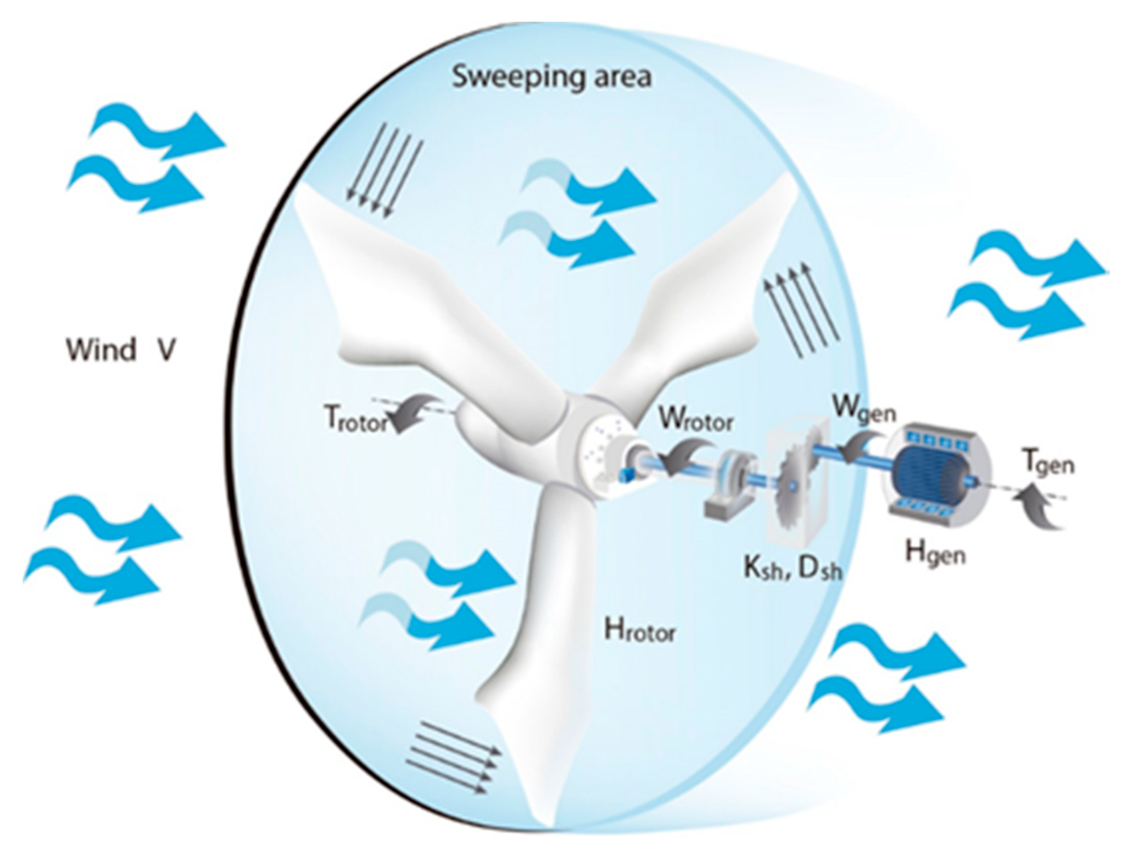
2. Wind Turbine Generator Systems
In a wind generation system, the rotor converts the kinetic energy of the wind into mechanical energy, and, in turn, spins the generator shaft, multiplying the rotation speed by means of a gearbox [
29]. To analyze the mechanical part, a simplified two-mass model is used, represented in Equations (1) to (9) [
30]. The rotor torque and the generator electromechanical torque act in opposition, and the resulting torque generates a speed on the rotor shaft
wr and speed on the generator shaft
wg.
where
ktg and
dtg are the constants of elasticity and damping, respectively, of the mechanical two-mass model [
18].
θm is the gearbox angular position.
Hr and
Hg are the rotor inertial and generator inertial moments, respectively, and they are calculated according to:
where
Pn is the nominal power,
Jg is the known inertia of the generator, and the inertia of the rotor
Jr can be approximated according to:
where
mr is the mass of the rotor and blades, and R is the length of the blade.
The torque of the rotor
Tr extracted by the blades is determined from the wind
v that crosses the sweeping area, and it is described with the following equation [
31]:
The wind density is
ρ and
Cp is the power coefficient.
Cp can be calculated in relation to TSR λ and the pitch angle
β by an approximate method described in Equation (7) [
32]:
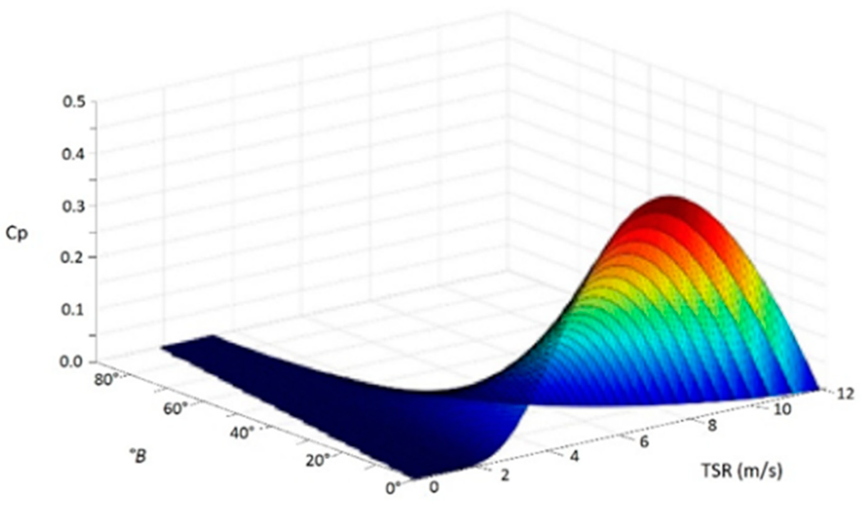
where Ω is the rotation frequency in rad/s. In
Figure 1, the influence of the pitch angle in
Cp is shown.
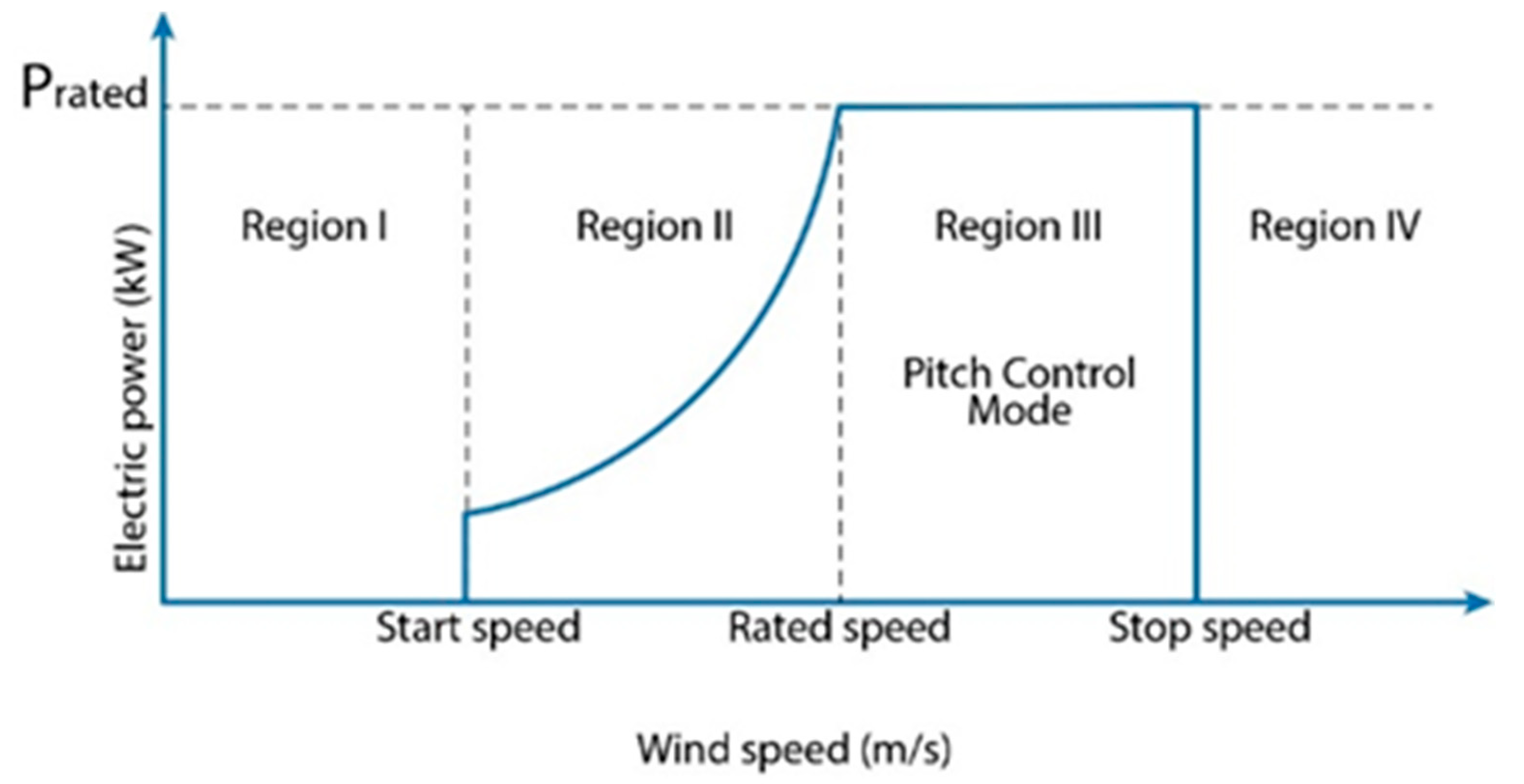
For this reason, with the pitch angle, it is possible to control speed, acceleration, and deceleration in the rotor, and mechanical stress in the system and electrical current overshoots are reduced [
7]. According to the wind speed, the operation of the turbine is divided into four regions, in each of which the objective of the pitch control is different. In region I, the wind is not sufficient to move the rotor; the blade must be in the flag position to avoid possible movement. The objective of pitch control in region II is to maximize energy production through maximum power point tracking (MPPT), as, in this region, the rotor begins to rotate and limits the nominal wind speed. In region III, the wind speed is higher than the nominal speed and pitch control is required to keep the nominal rotation speed constant; the limit is the maximum design wind speed. For region IV, it is required to stop the rotation of the rotor for safety, so the blades should be in the flag position [
33,
34]. The regions of operation of a wind turbine are shown in
Figure 2.
A PMSG is mostly used in wind turbines as its characteristics allow efficient operation at variable speed and does not require additional energy consumption [
35]. To mathematically represent a PMSG, it is divided into two axes, the d-axis, representing the rotor winding, and the q-axis, displaced by synchronous rotation, 90 electrical degrees in the stator. Voltages
d-q are given respectively by the following equations [
36]:
where
Ld and
Lq are the inductances,
Rd and
Rq are the resistances, and
Id and
Iq are the currents, in axes
d and
q, respectively.
φf represents magnetic flux.
Electromechanical torque
Tg can be expressed as [
37]:
where
Pp is a pair of poles of the generator and
ωref is the reference speed for MPPT calculated from the generated power
P and is represented using the following equation:
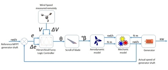
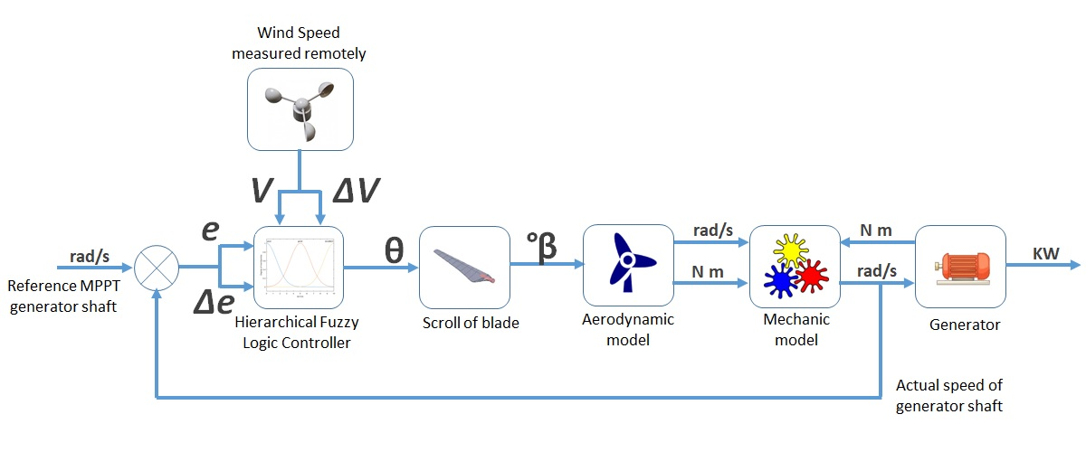
A schematic of the mathematical model of a wind turbine is shown in
Figure 3.
3. Methodology
This methodology describes the development of a pitch controller for a small horizontal-axis wind turbine (S-HAWT) considering wind randomness in turbulent places using fuzzy logic and wind measurements resolved over time at enough distance upstream of the rotor.
The membership functions of the controller are determined hierarchically by three levels of control. In the first level, the mathematical model is used to obtain the values of nominal wind speed, cut-in speed, and cut-off speed. In the second level, a statistical analysis of the wind speed variability is carried out at the installation site to determine the typical values of stable wind speed and those considered to be gusts. To anticipate a gust of wind, it is proposed to install a wind speed measurement system far enough away to allow time for the actuator to adapt the pitch angle. In the third level of control, the error of the controlled variable and the change in the magnitude of the error are used to obtain a fine control response.
3.1. Wind Turbine Especifications
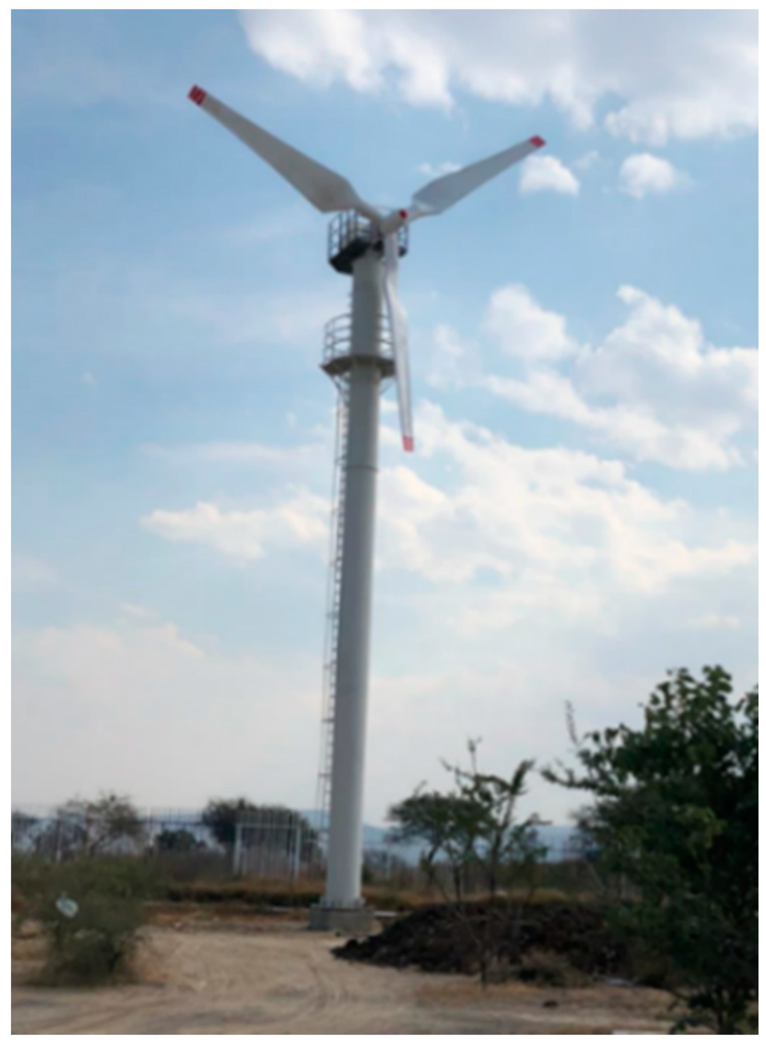
The test system is a 14 kW three-bladed wind turbine with a swept area of 134 m
2 and a tower height of 18 m from the ground to the rotor shaft. It has a gearbox with a gear ratio of 1:2.1 that transmits the movement of the rotor shaft to the generator shaft. In the rotor nose is the pitch angle positioning mechanism, which is actuated by a 0.5 HP direct current motor at 1750 rpm coupled to a reducer with a 60:1 transmission ratio; the motion is transmitted to each blade by a conical gear system. The mechanical design of the pitch angle movement increases the torque to reduce the effects of wind in the blades and to rotate without restriction; however, the speed is considerably reduced to 3°/s. The operating range of the pitch angle is between 0° and 90°, with 0° being the maximum possible wind power extracted, and 90° being where the wind does not impact the blades, making the rotor stop rotating. The S-HAWT installed on Universidad Autónoma de Querétaro (UAQ), airport campus, is shown in
Figure 4.
Each blade is made of fiberglass and polyester resin, weighing 260 kg each. Each blade is 6.4 m long and 1.2 m at its widest point, and the aerodynamic profile design is classified as NACA 6812 according to the National Advisory Committee on Aeronautics (NACA). The system has a nacelle equipped with a PMSG with a nominal power of 14 kW at 14.6 rad/s speed.
Table 1 indicates the design characteristics of the PMSG.
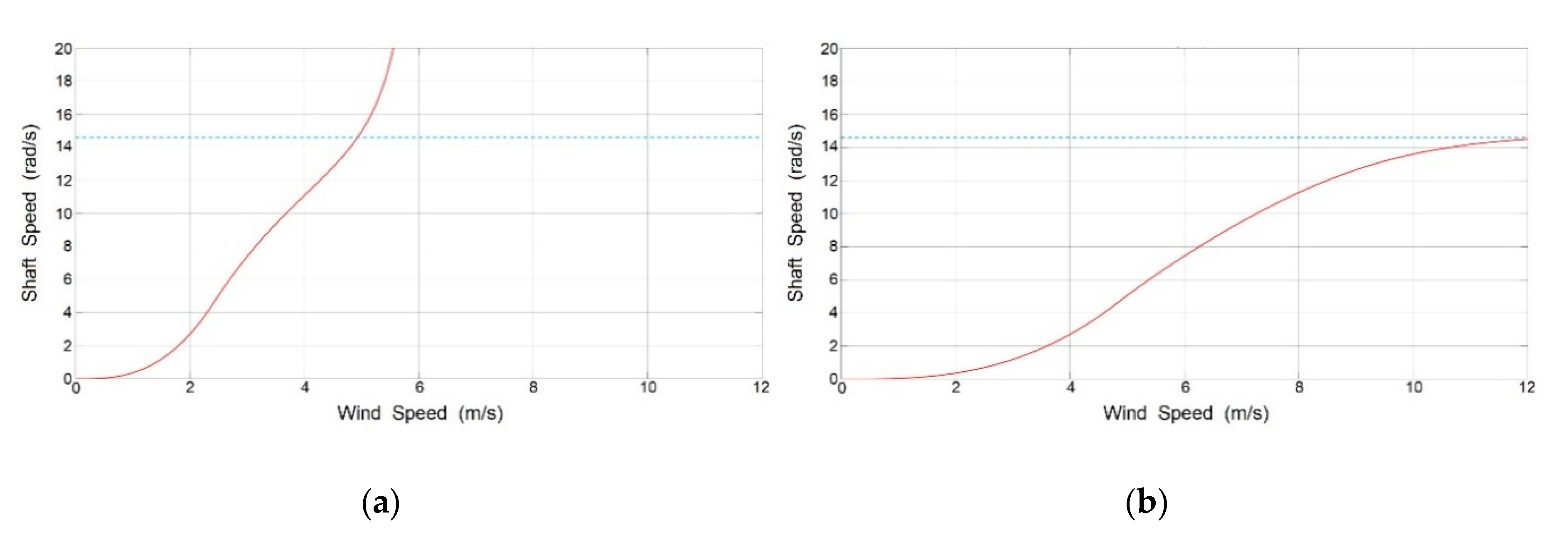
To determine the operational limits of the wind turbine, mathematical models of the aerodynamic system, mechanical system, and generator are used. MatLab-Simulink software [
38] and a HP Zbook 15 G4 workstation with Xeon 3.0 GHz processor and 32 GB RAM (64 bit) [
39] were used for simulations. A wind speed ramp from 0 to 15 m/s was simulated as the input variable. The results are shown in
Figure 5.
3.2. Local Wind Conditions Analysis
This research incorporates a meteorological study with data collected in the last 7 years in weather station #76628 SMN-CONAGUA, geographically located at 20°37′24.1″ N and 100° 22′06.0″ W at an altitude of 1969 m a.s.l. The data were collected at a ground level height of 18 m. A statistical analysis of meteorological variables was carried out, to analyze the factors that affect the wind behavior and operation of the wind turbine. A summary of this statistical analysis is shown in
Table 2.
In the relative frequency distribution, the data are grouped by each unit and the range of wind speeds that occur on more occasions is determined. The results obtained indicate that speeds between 3 and 4 m/s occurred 19.44% of the time. Values greater than 10 m/s had a recurrence of less than 1%, so they will not be considered for decision-making, and the controller will consider them as the cut-off wind speed. The average wind speed was 4.44 m/s with a standard deviation of 1.98 m/s, so wind speeds between the range of 2.46 and 6.42 m/s will be considered stable winds for controller decision-making. A histogram of wind speed with relative frequencies for each unit of magnitude of speed is shown in
Figure 6.
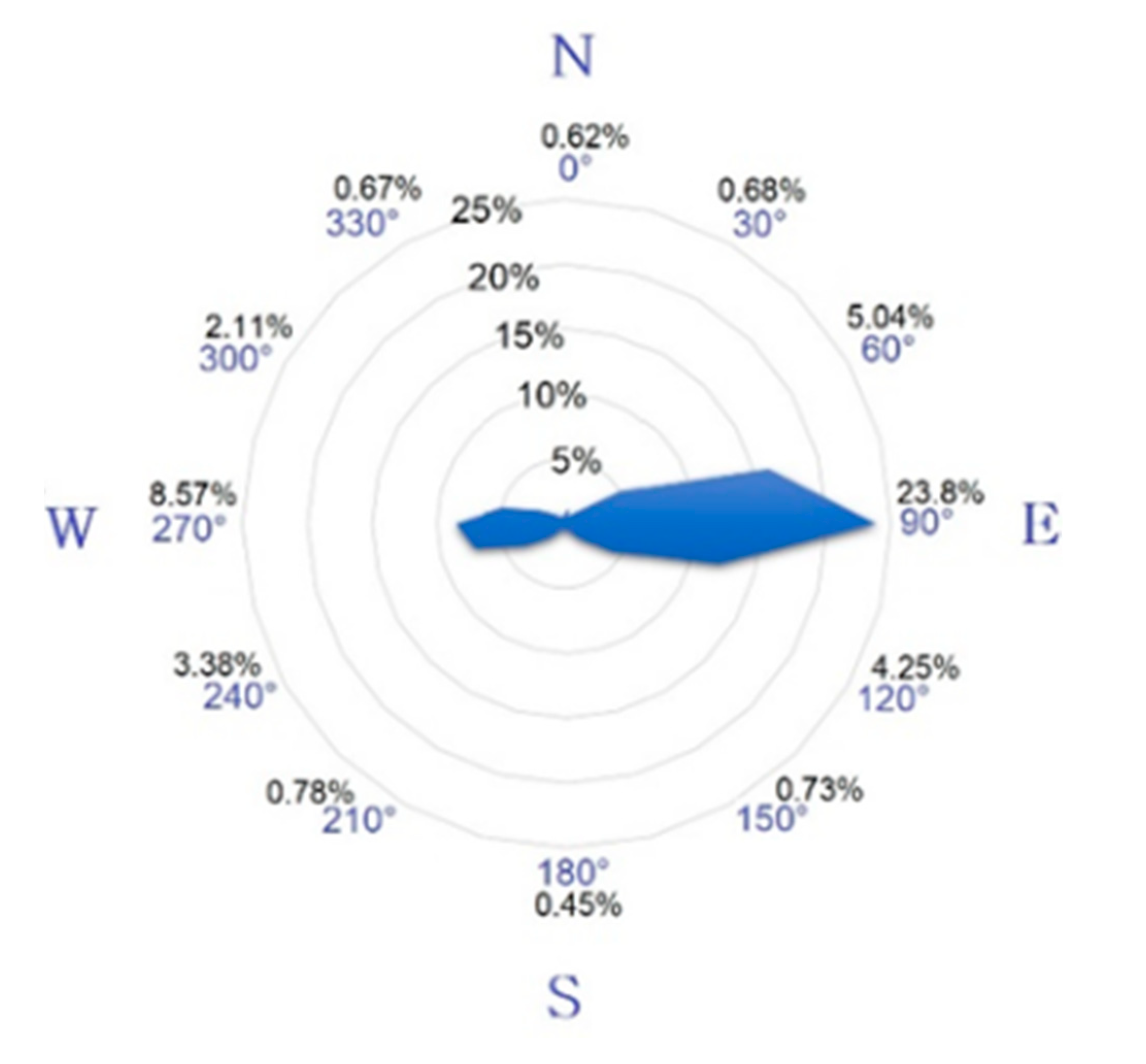
Information on the wind direction at the installation site is also obtained; a direction mode of 83.3° (east to west) was obtained, which is interpreted as prevailing winds, where the range between 70° and 110° represents 72% of the recurrence in the wind direction. A summary of the wind direction data is shown in
Figure 7.
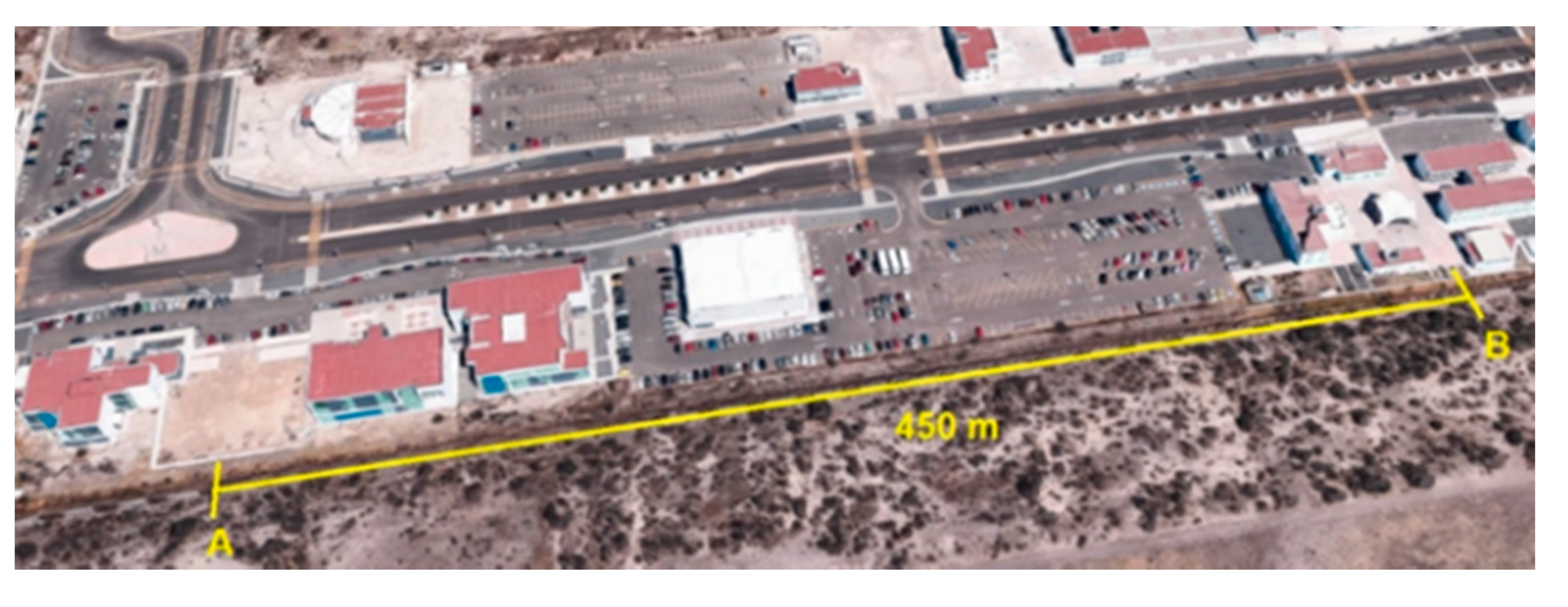
3.3. Place of Anemometer Instalation
With a wind speed meter located far enough to detect a gust, the controller gives the actuator the signal of the setpoint to adjust the pitch angle in advance, and by the time the gust is in the turbine, the rotor does not generate an overshoot of force that rotates the turbine above the cut-off speed, as this can cause damage to the mechanical system.
The data to determine the appropriate distance for the placement of an anemometer are the maximum rotation speed of the pitch angle equivalent to 3°/s; therefore, the time for the pitch angle to rotate from 0° to 90° is 30 s. In addition, the minimal speed considered for a gust is 10 m/s and the maximum wind speed historically presented at the installation site is 15 m/s, so the distance calculated to detect a wind speed of 15 m/s, 30 s in advance, is 450 m.
The mean of communication between the anemometer and controller located in the tower is carried out using the MODBUS industrial communication protocol with a transmission speed of 19,200 bps and a maximum distance of 1200 m [
40], so the delay in communication is not considerable.
The locations of the wind turbine and the proposed place for the installation of the anemometer are shown in
Figure 8.
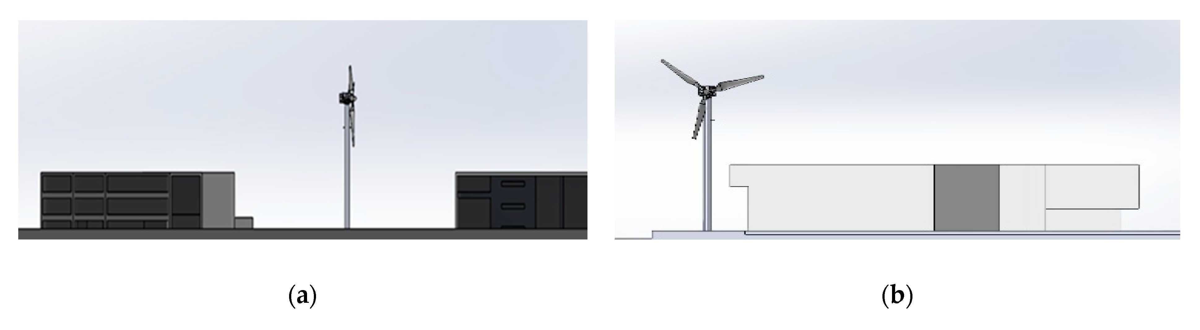
A dimensional analysis of the nearby buildings located in a straight line between the wind turbine and the anemometer is carried out to verify that the wind path is not affected and the wind speed measurements are not altered. Scale diagrams of the wind turbine and the buildings, with the height differences between buildings and the wind turbine, are shown in
Figure 9.
3.4. Hierarchical Fuzzy Logic Controller
An FLC is developed in three stages [
13,
14,
15].
- (1)
Fuzzification, converts the numerical value of the input variables into functions of belonging, based on intuition, deduction, data classification, or inductive reasoning.
- (2)
Fuzzy rules, using simple language statements, typically described in the Mamdani inference method, which is described by the following equation:
where the input variables
X1 and
X2 with constant values
A1 and
A2, respectively, generate the output variable
Y with a constant value
B.
- (3)
Defuzzification, converts the result of fuzzy rules to a numerical value of the output variable.
In this proposed hierarchical fuzzy logic controller (HFLC), the inputs for the controller are the value of wind speed
v, the value of the change in wind speed Δ
v, the error between rotor speed
ωgen and MPPT rotor speed
ωref, and the variation in error of generator speed Δ
eωgen. The input variables are described in the following equations:
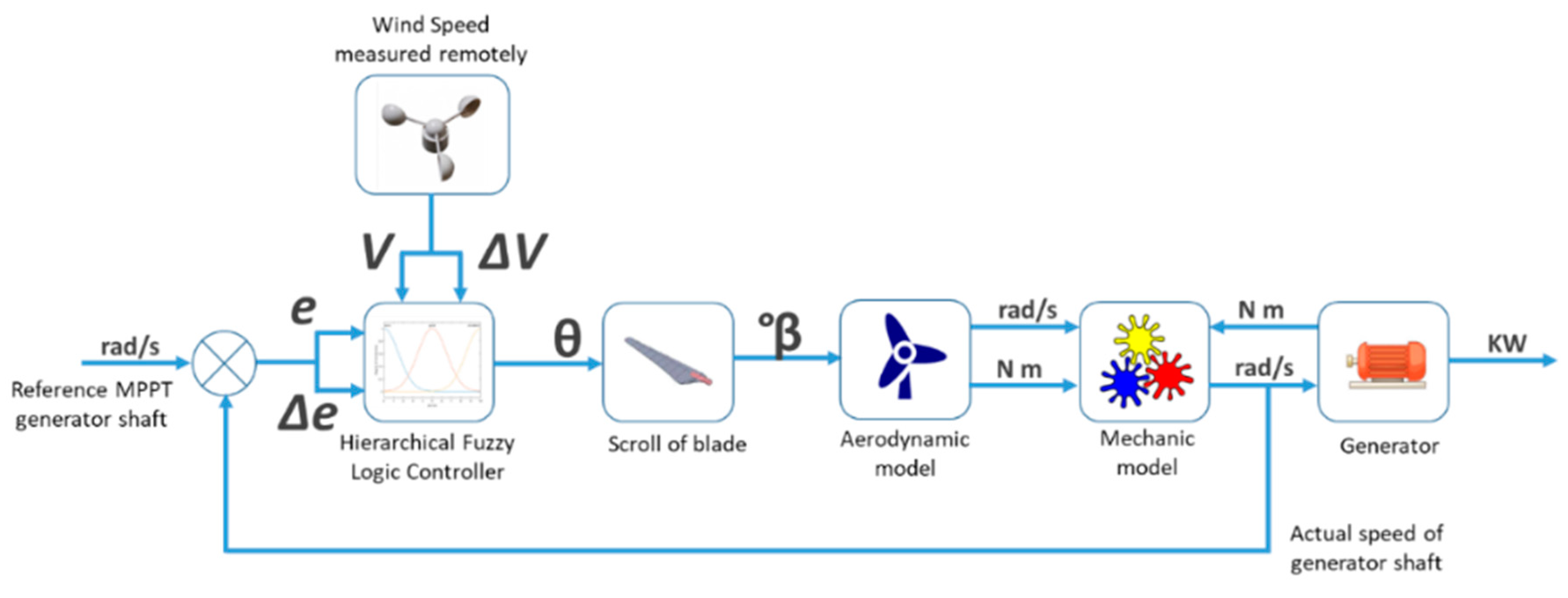
The proposed HFLC scheme for the pitch angle is shown in
Figure 10.
In this HFLC strategy, different levels of control are proposed. When the anemometer detects higher than nominal wind speeds in advance, or a significant change in wind speed, the controller anticipates the angle position. The closed loop of the rotor shaft speed determines the fine adjustment.
First level. According to the wind speed, the turbine’s operating region is located. Three linguistic levels are assigned for each region of operation with the following names: Region 1 (R_1), Region 2 y 3 (R_23), and Region 4 (R_4). The membership functions for wind speed are shown in
Figure 11.
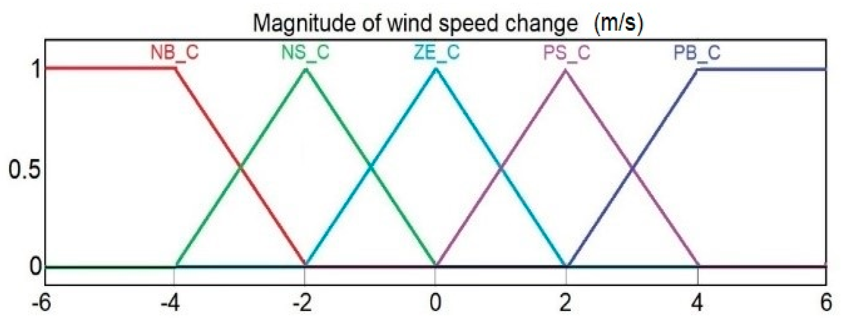
Second level. According to the magnitude of the change in wind speed. In region 2 and 3, it is important to consider changes in wind speed, as an abrupt change can accelerate the rotor and cause current spikes, saturate the generator, or physically damage the wind turbine. When a change in wind speed is detected in the anemometer at 450 m, the pitch angle moves in advance depending on the value of the magnitude of the change. Five linguistic levels are assigned for each magnitude of the change with the following names: Negative big (NB_C), negative small (NS_C), Zero (ZE_C), positive small (PS_C), and positive big (PB_C). The membership functions for changes in wind speed value are shown in
Figure 12.
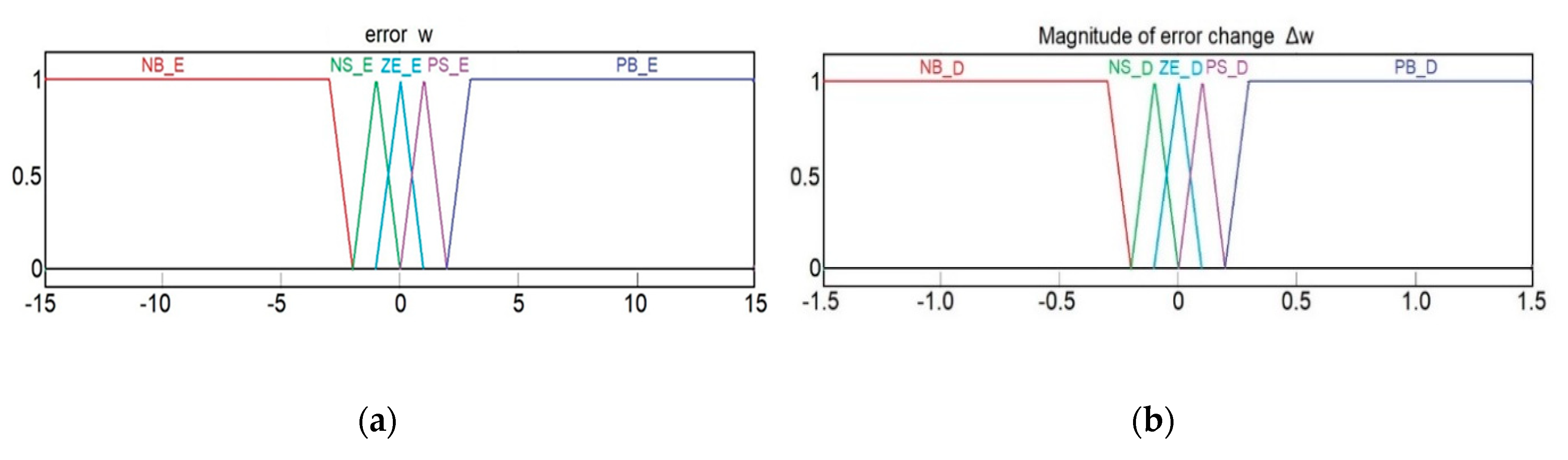
Third level. If there is no significant wind speed change, the level of control is based on finding the optimum angle to generate as much energy as possible, for which it considers the rotation speed error between the rotor speed and nominal speed, as well as the magnitude of the variation in the same error. Five linguistic levels are assigned according to the magnitude of the error with the following names: Negative big (NB_E), negative small (NS_E), Zero (ZE_E), positive small (PS_E), and positive big (PB_E). In addition, five linguistic levels are assigned according to the magnitude of the change in error value with the following names: Negative big (NB_D), negative small (NS_D), Zero (ZE_D), positive small (PS_D), and positive big (PB_D). These membership functions are shown in
Figure 13.
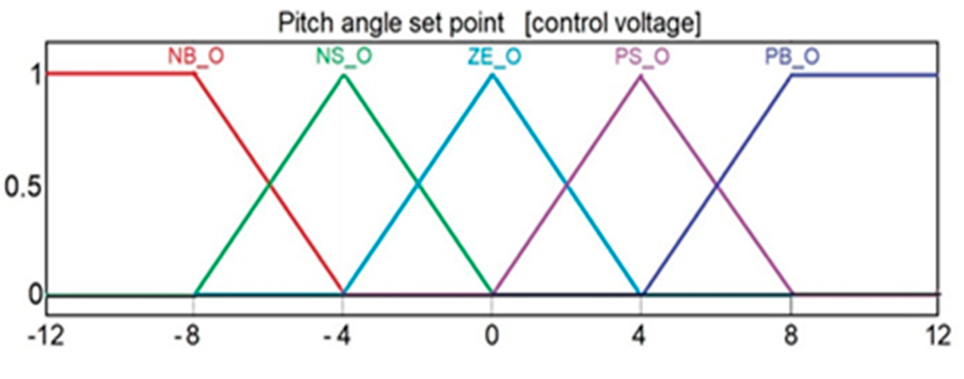
The output value has five linguistic levels with the following names: Negative big (NB_O), negative small (NS_O), Zero (ZE_O), positive small (PS_O), and positive big (PB_O). The membership functions for output in terms of the control voltage are shown in
Figure 14.
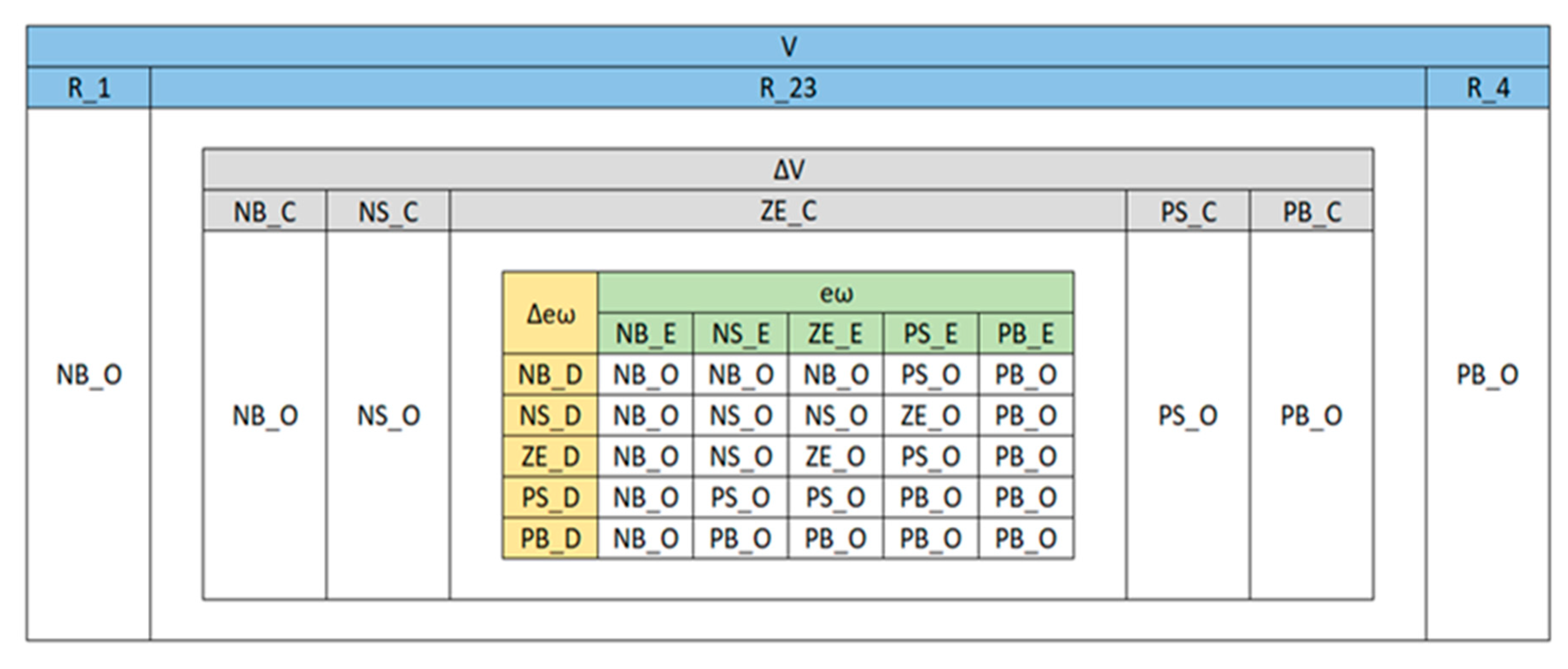
The relationships between input and output variables of the HFLC are defined by describing rules for each type of process behavior depending on the input variables, and these rules are defined using the linguistic variables. Authors propose 34 control rules for HFLC that were defined by their experience and knowledge. A Mamdani-type inference system is proposed, and input and output variables are generated using the triangular membership function. The centroid method is used for the defuzzification process. The rules for each level of control are shown in
Figure 15.
4. Discussion
To validate the algorithm, authors propose the use of a simulation with different wind speed values, where different circumstances were tuned for the algorithm to work at all levels. Step forms were used to represent the drastic changes in wind speed. The wind speed model used is shown in
Figure 16.
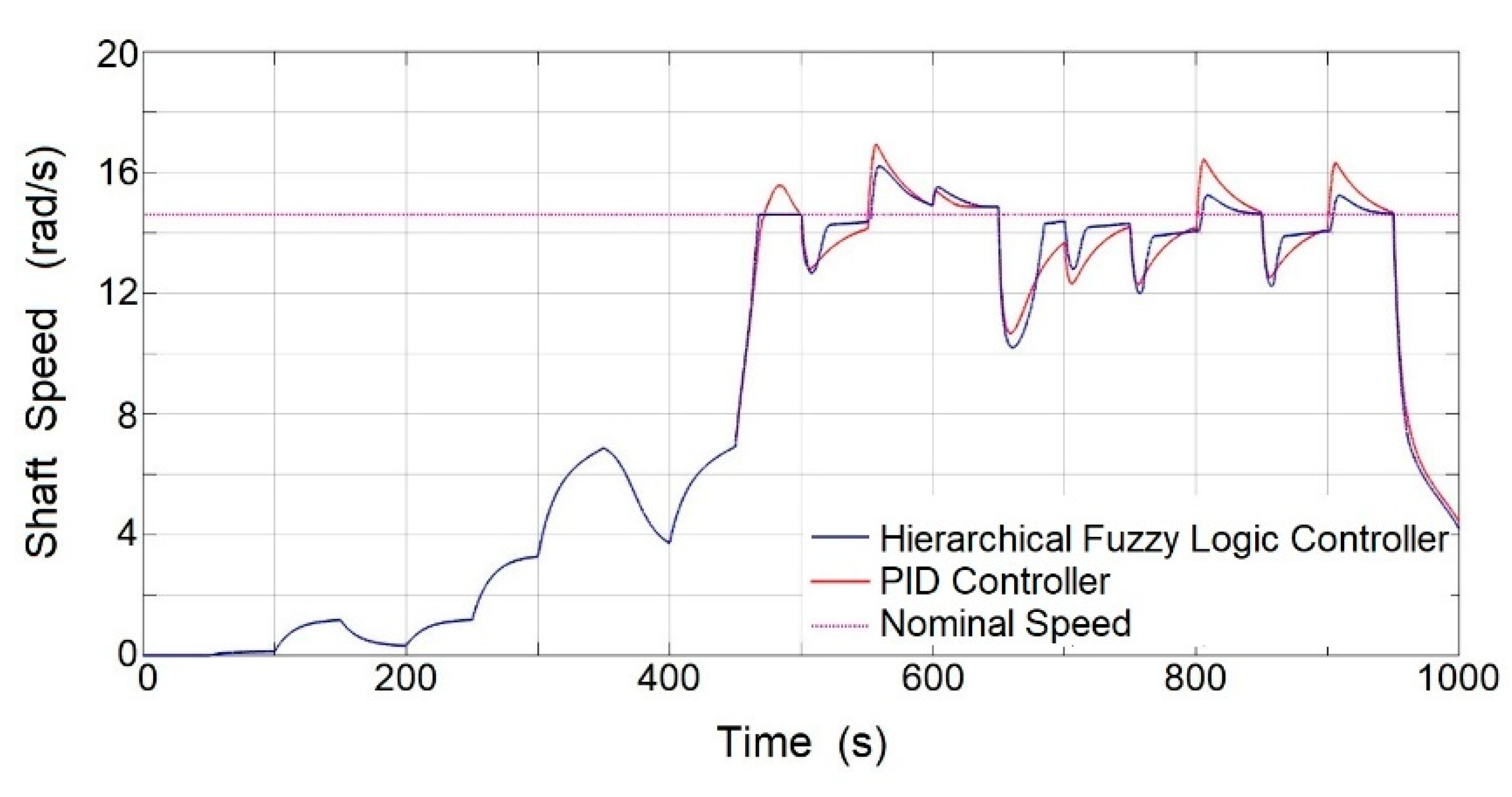
HFLC performance was compared against the performance of a classic PID controller without anticipated wind speed measuring to corroborate the advantages of locating a remote anemometer. The results obtained reflected in the rotation speed of the generator shaft are shown in
Figure 17. It is observed that before 450 s, the speed values of the generator shaft are lower than the nominal value. After 450 s, the rotation speed is maintained around the nominal speed of 14.6 rad/s, and it is observed that the HFLC makes the changes as fast as the drastic changes in the wind speed. In addition, the controller detects changes in the magnitude of the error and executes a response action with a value selected by the programmer that responds as quickly as is convenient according to different circumstances. By contrast, the controller based on a mathematical model has a control response proportional to the magnitude of the error in any circumstance.
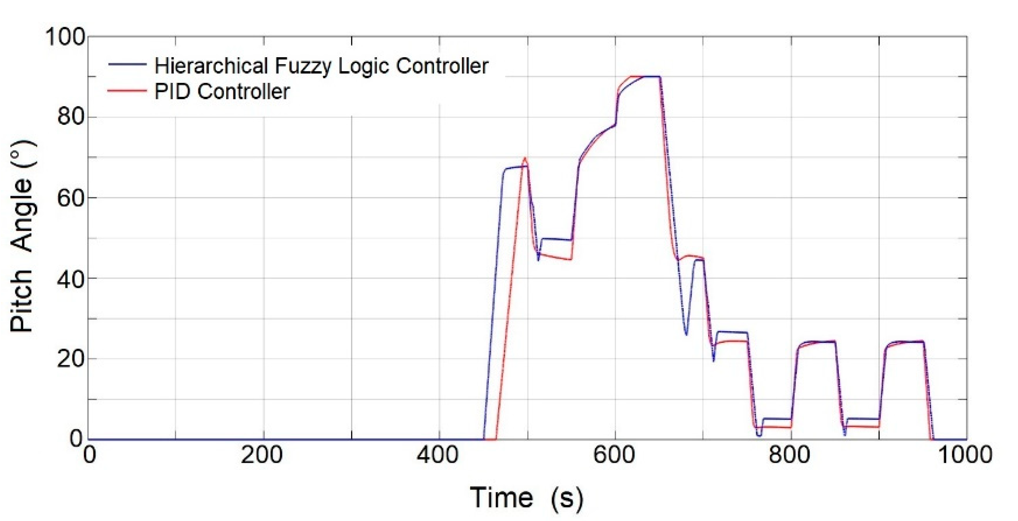
In
Figure 18, the pitch angle movement is documented, and it is observed at 450 s that the controller detects a drastic change in wind speed, the pitch angle movement starts immediately, and the PID controller without anticipated wind speed measuring starts movement 20 s later. It is also observed that with the HFLC, the actuator moves long distances until reaching the small error range, which results in a lower error in the generator shaft speed. On the other hand, the PID controller dampens the paths of the actuator as the error is reduced, so reduction with the error in the generator shaft speed is slower.
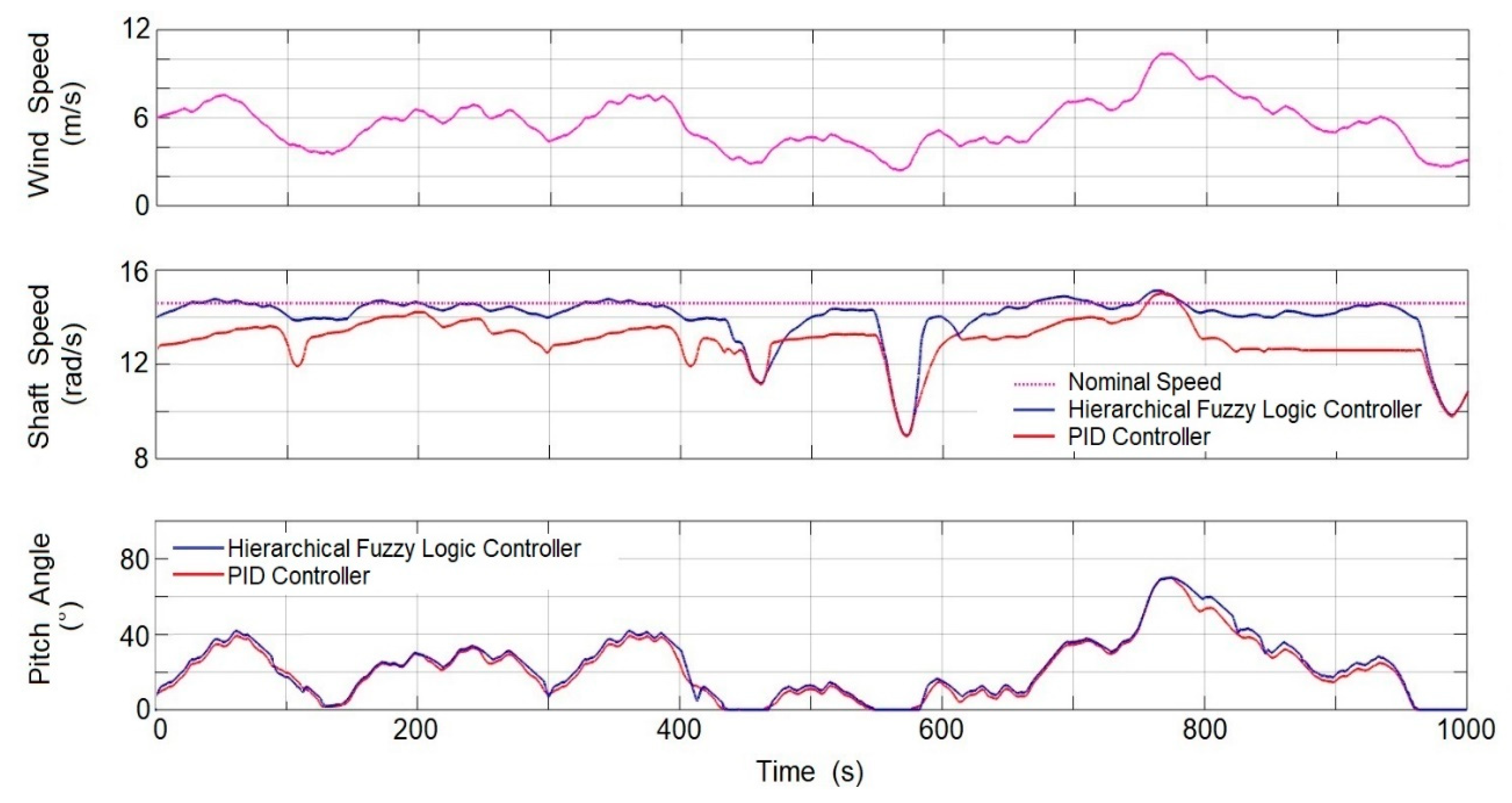
To carry out the experiment, only real winds in the predominant direction between 70° and 110° are considered, which represents 72% of the annual time. When the wind direction is in another direction range, the controller switches to a conventional PID controller. The development of the algorithm in real operating conditions is shown in
Figure 19.
Graphical results show that an HFLC has a better performance than a PID controller, as the value of the rotation speed of the generator shaft is always closer to the value of the nominal speed. According to a variable integration procedure, the average speed of the generator shaft with the HFLC is 14.159 rad/s, while with the PID controller, it was 12.753 rad/s. In general terms, the proposed control algorithm proved to be more efficient in the region of operation III, maintaining the nominal rotation speed of the generator up to 11% longer with respect to the controlled PID. This result is very significant because the longer the speed the generator shaft is at the nominal value, in the region of operation II, the more electrical energy will be produced, and in region III, generation losses due to magnetic saturation in the generator will be avoided. This result confirmed that a controller based on fuzzy logic, and in advance of the measurement of wind speed, has a better performance when programmed with decision criteria based on the experience of the programmer and statistical wind speed data, compared to a controlled PID or any of its variants because the latter reacts under a mathematical model.
5. Conclusions
In this document, a methodology for the development of an HFLC for a S-HAWT has been presented. This size of turbines is installed where the wind resources are limited; however, at the height to the center of the rotor axis, the wind is usually atypical, because at this height, the path of the wind encounters obstacles such as buildings, trees, mountains, or hillsides, which cause turbulence and gusts of wind. In these atypical wind conditions, the use of a conventional pitch angle controller parameterized from a mathematical model such as a PID controller is not reliable, because the variability in the speed and direction of the wind makes this variable behave more as a disturbance to the system than as a stable input variable.
Furthermore, the response of the mechanical system of pitch angle is usually slow because it moves a large amount of blade mass; a slow system prevents the obtaining of an adequate response to wind gusts. The experiment showed that when the rotor rotates at a slower speed than the nominal speed, a gust of wind can go unnoticed, as it would hardly move a large amount of mass, but when the rotor rotates at near the nominal speed, a wind gust could greatly accelerate the rotor such that it would easily exceed the nominal speed and it would be difficult to control the generated inertia, causing damage to the tower structure and the generator.
To solve this problem, the methodology developed proposes to install a wind speed measurement system at a calculated distance where the movement of the mechanical system of the pitch angle will anticipate the position of the setpoint angle and minimize the effects of the wind gust on the rotation of the turbine. A statistical analysis of the wind resources at the installation site, to determine the average of the magnitude of the meteorological variables and their frequency distribution, helps to set the control limits, define the HFLC membership functions, and give greater flexibility to the controller in the decision-making.
The results showed faster changes in the pitch angle position, which maintained the rotation speed of the generator shaft at nominal values, but not with a conventional PID controller where speeds greater than the nominal were obtained for prolonged times. With the HFLC, the pitch angle displacement is extended until the error in the rotation speed of the generator shaft is reduced. When the error is minimal, the pitch angle displacement changes sharply in search of a new position, while with the PID controller, the pitch angle changes to a new position before the error is reduced, so the response speed of the actuator is smoother. This means that the mechanical design for the pitch angle shift when using an HFLC must be robust to withstand mechanical shock.
Finally, with the HFLC, the nonlinearities of the system are compensated, avoiding oscillations in the mechanical system of the pitch angle, mechanical fatigue of the rotor is reduced, and better turbine performance is obtained.
With these results, it is demonstrated than an HFLC developed with this methodology shows a better performance than a conventional PID controller applied in the S-HAWT. Therefore, the document presents a great contribution of low cost, which will help researchers, manufacturers, and developing countries where the wind resources have not yet been fully utilized, with a tool for the control of the pitch angle in the S-HAWT that simplifies and motivates the use of renewable energies.
Author Contributions
Conceptualization, E.C.-N. and J.C.J.-C.; methodology, E.C.-N.; system control, E.C.-N. and R.V.C.-S.; experiments, E.C.-N. and R.V.C.-S.; software, R.V.C.-S. and G.R.-L.; hardware, J.C.J.-C.; validation, J.G.R.-M. and G.R.-L.; formal analysis, M.T.-P.; investigation, E.C.-N.; resources, J.C.J.-C.; data curation, J.G.R.-M. and G.R.-L.; discussion, M.T.-P. and J.C.J.-C.; writing—original draft preparation, E.C.-N.; writing—review and editing, M.T.-P. and J.G.R.-M.; visualization, E.C.-N.; supervision, J.C.J.-C.; project administration, J.C.J.-C.; funding acquisition, J.C.J.-C. All authors have read and agreed to the published version of the manuscript.
Funding
This research received no external funding.
Acknowledgments
This work was supported by Investigación y Posgrado of the Facultad de Ingeniería and Universidad Autónoma de Querétaro.
Conflicts of Interest
Authors declare no conflict of interest.
References
- Wang, L.; Liu, X.; Kolios, A. State of the art in the aeroelasticity of wind turbine blades: Aeroelastic modelling. Renew. Sustain. Energy Rev. 2016, 64, 195–210. [Google Scholar] [CrossRef]
- González-González, A.; Jimenez-Cortadi, A.; Galar, D.; Ciani, L. Condition monitoring of wind turbine pitch controller: A maintenance approach. Measurement 2018, 123, 80–93. [Google Scholar] [CrossRef]
- MHI Vestas Offshore Wind A/S Dusager 4, 8200 Aarhus, Denmark. MHI Vestas Launches the First 10 MW Wind Turbine in History. Available online: https://mhivestasoffshore.com/mhi-vestas-launches-the-first-10-mw-wind-turbine-in-history/#:~:text=The%20offshore%20wind%20industry’s%20long,is%20available%20for%20sale%20now (accessed on 17 June 2018).
- IEC. Small Wind Turbines; IEC 61400-2:2013; IEC: Geneva, Switzerland, 2013; Volume 3, p. 11. [Google Scholar]
- Global Wind Atlas. V2.3 November 2018. Available online: www.https://globalwindatlas.info/area/Mexico (accessed on 17 June 2018).
- Bibave, R.; Kulkarni, V. A novel maximum power point tracking method for wind energy conversion system: A review. In Proceedings of the International Conference on Computation of Power, Energy, Information and Communication (ICCPEIC), Chennai, India, 28–29 March 2018. [Google Scholar]
- Novaes-Menezes, E.J.; Araújo, A.M.; Da Silva, N.S.B. A review on wind turbine control and its associated methods. J. Clean. Prod. 2018, 174, 945–953. [Google Scholar] [CrossRef]
- Menon, M.; Ponta, F. Dynamic aero elastic behavior of turbine rotors in rapid pitch-control actions. Renew. Energy 2017, 107, 327–339. [Google Scholar] [CrossRef]
- Behera, S.; Subudhi, B.; Pati, B.B. Design of PI controller in pitch control of wind turbine: A comparison of PSO and PS Algorithm. Int. J. Renew. Energy Res. 2016, 6, 1. [Google Scholar]
- Kumar, D.; Chatterjee, K. A review of conventional and advanced MPPT algorithms for wind energy systems. Renew. Sustain. Energy Rev. 2016, 1, 957–970. [Google Scholar] [CrossRef]
- Amulya, M.; Prashanth, C.; Vijaya, M. Controlling flicker caused due to power fluctuations by using individual pitch control for a variable speed DFIG based wind turbine. Int. Res. J. Eng. Technol. 2017, 4, 286–293. [Google Scholar]
- Chamorro, H.R.; Riaño, I.; Gerndt, R.; Zelinka, I.; Gonzalez-Longatt, F.; Sood, V.K. Synthetic inertia control based on fuzzy adaptive differential evolution. Int. J. Electr. Power Energy Syst. 2019, 105, 803–813. [Google Scholar] [CrossRef]
- Elfergani, A.; Elsharif, M.A.A.; Hamd, R.H.A.; Saad, S.M.; Naily, N.E.; Mohamed, F.A. Advanced self-tuned pitch angle control based on fuzzy logic for grid connected variable-speed wind turbine system. In Proceedings of the IEEE 9th International Renewable Energy Congress (IREC), Hammamet, Tunisia, 20–22 March 2018. [Google Scholar]
- Ayrir, W.; Ourahou, M.; El-Hassouni, B.; Haddi, A. Direct torque control improvement of a variable speed DFIG based on a fuzzy inference system. Math. Comput. Simul. 2018, 167, 308–324. [Google Scholar] [CrossRef]
- Mazouz, F.; Belkacem, S.; Ouchen, S.; Harbouche, Y.; Abdessemed, R. Fuzzy Control of a Wind System Based on the DFIG; Lecture Notes in Networks and Systems; Springer: Cham, Switzerland, 2018; pp. 173–181. [Google Scholar]
- Slah, H.; Mehdi, D.; Lassaad, S. Advanced control of a PMSG wind turbine. Int. J. Mod. Nonlinear Theory Appl. 2016, 5, 1–10. [Google Scholar] [CrossRef]
- Kesraoui, M.; Lagraf, S.A.; Chaib, A. Aerodynamic power control of wind turbine using fuzzy logic. In Proceedings of the IEEE 3rd International Renewable and Sustainable Energy Conference (IRSEC), Marrakech & Ouarzazate, Marrakech, Morocco, 10–13 December 2015. [Google Scholar]
- Ben-Smida, M.; Sakly, A. Fuzzy pitch angle control for grid connected variable-speed wind turbine system. In Proceedings of the IEEE 7th International Renewable Energy Congress, Hammamet, Tunisia, 22–24 March 2016. [Google Scholar]
- Slimen, A.; Tlijani, H.; Dhaoui, M.; Younes, R.B. Intelligent control of wind pump based on PMSG using pitch control. In Proceedings of the IEEE 14th International Multi-Conference on Systems, Signals and Devices (SSD), Marrakech Tensift El Haouz, Marrakech, Morocco, 30 March 2017. [Google Scholar]
- Al-Toma, A.S.; Taylor, G.A.; Abbod, M. Intelligent pitch angle control scheme for variable speed wind generator systems. In Proceedings of the IEEE 52nd International Universities Power Engineering Conference (UPEC), Crete, Grece, 28–31 August 2017. [Google Scholar]
- Habibi, H.; Rahimi, H.; Howard, I. Power maximization of variable-speed variable-pitch wind turbines using passive adaptive neural fault tolerant control. Front. Mech. Eng. 2017, 12, 377–388. [Google Scholar] [CrossRef]
- Zheng, X.; Ding, D.; Li, P. Power stable regulation of direct-drive permanent magnet wind. In Power System Using Pitch and Torque Control; Electrical Engineering Department, Harbin Institute of Technology: Harbin, China, 2015. [Google Scholar]
- Narasimalu, S.; Chellaiah, B. Pitch angle control for horizontal axis wind turbine: A comparative study. In Proceedings of the IEEE Asian Conference on Energy, Power and Transportation Electrification (ACEPT), Singapore, 24–26 October 2017. [Google Scholar]
- Tiwari, R.; Ramesh, N.; Sanjeevikumar, P. Fuzzy logic-based pitch angle controller for PMSG-based wind energy conversion system. In Advances in Smart Grid and Renewable Energy; Springer: Singapore, 2017; pp. 277–286. [Google Scholar]
- Van, T.L.; Nguyen, T.H.; Lee, D.C. Advanced pitch angle control based on fuzzy logic for variable-speed wind turbine systems. IEEE Trans. Energy Convers. 2015, 30, 578–587. [Google Scholar] [CrossRef]
- Renuka, T.K.; Reji, P. Frequency control of wind penetrated hydro-dominated power system. In Proceedings of the IEEE International Conference on Technological Advancements in Power and Energy (TAP Energy), Kollam, India, 24–26 June 2015. [Google Scholar]
- Zeddini, M.A.; Pusca, R.; Mansouri, M.N.; Mimouni, M.F. TSK fuzzy controller of wind-turbine self-excited induction generator for remote site applications. In Proceedings of the IEEE 16th International Conference on Sciences and Techniques of Automatic Control and Computer Engineering (STA), Monastir, Tunisia, 21–23 December 2015. [Google Scholar]
- Chavero-Navarrete, E.; Trejo-Perea, M.; Jáuregui-Correa, J.C.; Carrillo-Serrano, R.V.; Ríos-Moreno, G. Expert control systems implemented in a pitch control of wind turbine: A review. IEEE Access 2019, 7, 13241–13259. [Google Scholar] [CrossRef]
- Chavero-Navarrete, E.; Trejo-Perea, M.; Jáuregui-Correa, J.C.; Carrillo-Serrano, R.V.; Ríos-Moreno, J.G. Expert control systems for maximum power point tracking in a wind turbine with PMSG: State of the art. Appl. Sci. 2019, 9, 2469. [Google Scholar] [CrossRef]
- Muyeen, S.M.; Hasan-Ali, M.; Takahashi, R.; Murata, T.; Tamura, J.; Tomaki, Y.; Sasano, E. Comparative study on transient stability analysis of wind turbine generator system using different drive train models. IET Renew. Power Gener. 2007, 1, 131–141. [Google Scholar] [CrossRef]
- Giannakis, A.; Karlis, A.; Karnavas, Y.L. A combined control strategy of a DFIG based on a sensorless power control through modified phase-locked loop and fuzzy logic controllers. Renew. Energy 2018, 121, 489–501. [Google Scholar] [CrossRef]
- Yang, B.; Yu, T.; Shu, H.; Zhang, Y.; Chen, J.; Sang, Y.; Jiang, L. Passivity-based sliding-mode control design for optimal power extraction of a PMSG based variable speed wind turbine. Renew. Energy 2018, 119, 577–589. [Google Scholar] [CrossRef]
- Soued, S.; Ebrahim, M.A.; Ramadan, H.S.; Becherif, M. Optimal blade pitch control for enhancing the dynamic performance of wind power plants via metaheuristic optimizers. IET Electr. Power Appl. 2017, 11, 1432–1440. [Google Scholar] [CrossRef]
- Asghar, A.B.; Liu, X. Estimation of wind turbine power coefficient by adaptive neuro-fuzzy methodology. Neurocomputing 2017, 238, 227–233. [Google Scholar] [CrossRef]
- Honrubia-Escribano, A.; Gómez-Lázaro, E.; Fortmann, J.; Sørensen, P.; Martin-Martinez, S. Generic dynamic wind turbine models for power system stability analysis: A comprehensive review. Renew. Sustain. Energy Rev. 2018, 81, 1939–1952. [Google Scholar] [CrossRef]
- Gong, J.; Xie, R. MPPT Control by using a U-P Curve for PMSG based small wind turbines. J. Energy Eng. 2015, 142, 138–149. [Google Scholar] [CrossRef]
- Eisa, S.A. Modeling dynamics and control of type-3 DFIG wind turbines: Stability, Q Droop function, control limits and extreme scenarios simulation. Electr. Power Syst. Res. 2019, 166, 29–42. [Google Scholar] [CrossRef]
- MATLAB, version 9.5.0.944444 (R2018b); The MathWorks Inc.: Natick, MA, USA, 2018.
- Hewlett-Packard, Palo Alto, CA, USA. 2018. Available online: https://support.hp.com/mx-es/product/hp-zbook-15-g4-mobile-workstation/14840009/document/c05490313 (accessed on 1 June 2020).
- Modbus Organization. MODBUS Application Protocol Specification V1.1b3. 2012. Available online: www.modbus.org (accessed on 1 June 2020).
Figure 1.
The influence of the pitch angle in Cp. If the value of β increases, Cp decreases.
Figure 1.
The influence of the pitch angle in Cp. If the value of β increases, Cp decreases.
Figure 2.
Operating regions of a wind turbine. In region III, pitch control is used to counteract strong winds and keep the nominal rotation speed constant.
Figure 2.
Operating regions of a wind turbine. In region III, pitch control is used to counteract strong winds and keep the nominal rotation speed constant.
Figure 3.
Schematic of the mathematical model of a wind turbine. All bodies exposed to an airflow experience an aerodynamic force that can be broken down into a pulling force in the wind direction and a lifting force perpendicular to the wind direction, which is the force that will cause the rotor to turn.
Figure 4.
Three-blade wind turbine installed on Universidad Autónoma de Querétaro (UAQ).
Figure 4.
Three-blade wind turbine installed on Universidad Autónoma de Querétaro (UAQ).
Figure 5.
In (a), a pitch angle of 0° was used and the wind turbine starts rotating with a wind speed of 1 m/s; in addition, nominal rotation speed in the generator shaft was reached at 14.6 rad/s at a wind speed of 4.9 m/s. In (b), a pitch angle movement from 0° to 60° was simulated to determine the wind speed to where the pitch system can decrease the wind force on the blades. It is observed that with a wind speed of 11.83 m/s and at an angle of 60°, the nominal speed on the generator shaft is reached. With a higher wind speed of 11.83 m/s, the pitch angle must be positioned at 90°.
Figure 6.
Histogram of wind speed with relative frequencies for each unit of magnitude of speed.
Figure 6.
Histogram of wind speed with relative frequencies for each unit of magnitude of speed.
Figure 7.
Wind direction distribution.
Figure 7.
Wind direction distribution.
Figure 8.
Installation area of the wind turbine and anemometer. Letter A indicates the installation site of the wind turbine, and letter B is the installation site for the anemometer.
Figure 8.
Installation area of the wind turbine and anemometer. Letter A indicates the installation site of the wind turbine, and letter B is the installation site for the anemometer.
Figure 9.
Scale perspective of the wind turbine and nearby buildings. (a) Side view, (b) front view.
Figure 9.
Scale perspective of the wind turbine and nearby buildings. (a) Side view, (b) front view.
Figure 10.
Proposed hierarchical fuzzy logic controller (HFLC) scheme for the pitch angle.
Figure 10.
Proposed hierarchical fuzzy logic controller (HFLC) scheme for the pitch angle.
Figure 11.
Membership functions for wind speed.
Figure 11.
Membership functions for wind speed.
Figure 12.
Membership functions for changes in wind speed value.
Figure 12.
Membership functions for changes in wind speed value.
Figure 13.
Membership functions for: (a) Error of generator shift speed, (b) magnitude of error changes.
Figure 13.
Membership functions for: (a) Error of generator shift speed, (b) magnitude of error changes.
Figure 14.
Membership functions for output value.
Figure 14.
Membership functions for output value.
Figure 15.
Outline of the control rules at each hierarchical level.
Figure 15.
Outline of the control rules at each hierarchical level.
Figure 16.
Wind speed values used for simulation. In the first 100 s, there are winds corresponding to region 1. Between 100 and 450 s, the wind turbine is maintained in region 2 with values lower than the nominal speed. After 450 s, the wind turbine is in region 3. Only between 600 s and 650 s are there values from region 4.
Figure 17.
Rotation speed of generator shaft. Differences in performance between the HFLC and the PID controller are observed. The HFLC shows better performance as, in operating region III, it greatly reduces the error in the speed of the rotor shaft with respect to nominal speed.
Figure 17.
Rotation speed of generator shaft. Differences in performance between the HFLC and the PID controller are observed. The HFLC shows better performance as, in operating region III, it greatly reduces the error in the speed of the rotor shaft with respect to nominal speed.
Figure 18.
Pitch angle movement. There is also a difference in the pitch angle paths, where the HFLC makes sudden (peak-shaped) changes in the angle path, while the PID controller makes smooth changes.
Figure 18.
Pitch angle movement. There is also a difference in the pitch angle paths, where the HFLC makes sudden (peak-shaped) changes in the angle path, while the PID controller makes smooth changes.
Figure 19.
Experiment with real wind conditions. The behavior of the wind at the time of the experiment is shown in the upper part of the figure. The comparison of the generator shaft rotation speed using the HFLC and PID controllers is shown in the middle of the figure. The pitch angle movement with both controllers is shown in the lower part of the figure.
Table 1.
Permanent magnet synchronous generator (PMSG) specifications.
Table 1.
Permanent magnet synchronous generator (PMSG) specifications.
| Nominal Power | 14 kW | Frequency | 20.33 Hz |
|---|
| Voltage | 385 V | F.P. | 0.94 |
| Current | 22.2 A | Ins. Class | H |
| Nominal Speed | 135 RPM | Service | Continuous |
| Frame | TC5V | Inc. Temp | 80 °C |
| Class | IP32 | Weight | 650 Kg |
Table 2.
Statistical analysis of meteorological variables.
Table 2.
Statistical analysis of meteorological variables.
| Meteorological Variables | Wind Speed (m/s) at 18 m Height | Temperature (°C) | Relative Humidity (%) | Atmospheric Pressure (mbar) |
|---|
| Mean | 4.44 | 17.72 | 58.26 | 806.99 |
| Standard Error | 0.01 | 0.03 | 0.13 | 0.01 |
| Median | 4.24 | 16.88 | 57.00 | 807.05 |
| Mode | 3.62 | 14.25 | 98.67 | 807.27 |
| Std. Deviation | 1.98 | 6.27 | 26.20 | 2.27 |
| Variance | 2.72 | 39.52 | 688.25 | 5.15 |
| Range | 15.00 | 37.57 | 95.50 | 15.70 |
| Minimum | 0.00 | 0.23 | 4.50 | 798.85 |
| Maximum | 15.00 | 37.80 | 100.00 | 814.55 |
© 2020 by the authors. Licensee MDPI, Basel, Switzerland. This article is an open access article distributed under the terms and conditions of the Creative Commons Attribution (CC BY) license (http://creativecommons.org/licenses/by/4.0/).

 ,
, 


