Article

Chatter and Stability Analysis of the Slender Composite Boring Bar with Constrained Damping Layer

1
College of Mechanical and Electronic Engineering, Shandong University of Science and Technology, Qingdao 266590, China
2
Engineering Training Center, Shandong University of Science and Technology, Qingdao 266590, China
*
Authors to whom correspondence should be addressed.
Appl. Sci. 2020, 10(13), 4537; https://doi.org/10.3390/app10134537
Submission received: 27 May 2020 / Revised: 25 June 2020 / Accepted: 28 June 2020 / Published: 30 June 2020
(This article belongs to the Section Acoustics and Vibrations)

Abstract

:
This study investigates the chattering stability of the composite boring bar with a constrained damping layer during the deep-hole boring process in depth. Based on the Euler-Bernoulli beam theory, the regenerative chattering linear kinetic model of the composite boring bar with a constrained damping layer was established, and the computational formulas of the rotating speed of the spindle and the corresponding limit cutting depth were derived. By analyzing the chattering stability, the cutting stability lobe curves of the composite boring bar with a constrained damping layer were plotted so as to reveal the effects of the materials of both base layer and constrained layer, the ply angle, the damping composite structure (free or constrained damping structure) and the thickness of various layers on the chattering stability of the boring bar. Through the analysis of dynamic stiffness, the chatter stability analysis theory of a composite boring bar with a constrained damping layer is verified.

1. Introduction

With the development of modern industrial technology, deep-hole processing now has witnessed more and more extensive applications in many domains, accompanied by increasingly high requirements on processing precision and quality [1]. High-precision deep-hole boring has become difficult in machining since cutting chattering is extremely easily generated during the machining process. This can be attributed to a great length-to-diameter ratio and small dynamic rigidity of the metal-boring bar, thereby reducing processing quality and machining quality on the surface of the workpiece. Accordingly, the machining requirements can hardly be satisfied, and the cutter’s service life would be shortened. Research demonstrates that a steel cutter may reach the performance limit in mechanical processing when the overhanging length-to-diameter ratio exceeds 4 (L/D > 4). Further increasing the overhanging length-to-diameter ratio may result in chattering. By contrast, because of great rigidity, a hard alloy cutter may have an overhanging length-to-diameter ratio of up to 6. Therefore, how to reduce the chattering of the boring bar has become a research hotspot.
In terms of control mode, the vibration attenuation techniques for a boring bar can be divided into active vibration attenuation, semi-active vibration attenuation, and passive vibration attenuation techniques. As a control strategy, an active-control vibration isolation system achieves active control of the vibration via the input energy based on the detected vibration signal. Despite favorable adaptation to various vibration isolation environments, the active-control vibration isolation system consumes a great amount of energy and may be unstable sometimes.
Semi-active damping attenuation refers to realizing real-time regulation without the input of energy. Semi-active control vibration isolation can change some of the system’s characteristics, such as system rigidity, and adjust the vibration in accordance with damping in different vibration environments, which only requires low external energy input and has a relatively simple structure.
The passive control vibration isolation system only relies on the system’s elastic components and damping or the additive dynamic vibration absorber to realize the suppression of chattering. In terms of vibration attenuation principle, the passive vibration isolation of the cutter can be divided into material vibration attenuation, friction vibration attenuation, damping vibration attenuation, and dynamic vibration attenuation.
Material vibration attenuation refers to using high-strength high-performance materials to enhance the cutter quality and static rigidity, thereby achieving the goal of chattering prevention. Andrénet al. conducted cutting tests on boring cutters with different materials and measured their dynamic characteristics by examining their vibration damping performances [2]. Lee et al. found that the composite boring bar made up of high-rigidity asphalt-based carbon fiber epoxy composites exceeded the common tungsten-alloy (W-ally) boring bar in terms of higher rigidity and damping compared to [3]. Moreover, the experimental results demonstrated that the boring bar exhibited no obvious chattering at a length-do-diameter ratio of 10.7 [3]. Through comparison, Wang Jun et al. concluded that the carbon fiber boring bar with composite structure performed better than the hard-alloy boring bar in vibration damping performance [4]. Jing Qingwu, Guo Zhi et al. developed a kind of composite boring bar consisting of hard alloy YT14 and 45 steel and found that the inherent frequency of the novel composite boring bar was higher than that of the traditional boring bar [5]. Wu Nengzhang et al. performed cutting tests on both ordinary and composite vibration-attenuation boring bars under the same cutting conditions [6]. The results showed that the chattering amplitude of the composite boring bar was far below that of the ordinary boring bar, suggesting the favorable vibration suppression performance of the composite boring bar. Wang Min et al. proposed a friction-based vibration attenuation boring bar to suppress the vibration via the Coulomb friction damping generated by the friction oscillator [7]. By embedding the friction damper into the boring bar, Evita Edhi and Tetsutaro Hoshi achieved a satisfactory friction vibration attenuation effect of the boring bar in accordance with the mass of the permanent block, the mass of the vibration core, and the spatial relation between them. Accordingly, the friction vibration attenuation was achieved, and high-frequency chattering at around 10,000 Hz was effectively suppressed [8]. Du Jingxuan et al. proposed a kind of particle damping boring bar [9]. By adding particles to the ordinary boring bar, the vibration energy can be consumed by the collision and friction among particles.
Using dynamic vibration attenuation, an additive mass block is connected to the vibration system by elastic components. The generated force under the action of the additive mass equals the excitation force in magnitude but is opposite in direction. Accordingly, the vibration can be eliminated or weakened. Moradi et al. designed the dynamic vibration absorber for the vibration attenuation boring bar and optimized various parameters [10]. Xie Feng et al. found that the boring bar, including the embedded-in metal damping core with large density, exhibited a better damping effect than the boring bars with single structures, such as flat structures and circular structures [11]. He Miao et al. transformed the vibration at the cutter bit into the vibration of the dynamic vibration absorber to achieve the damping effect and dissipated the vibration energy with the use of the injected damping oil [12]. Kang Wei et al. pointed out that although the dynamic damping composite boring bar with two degrees of freedom (DOFs) had slightly lower first-order inherent frequency than the composite dynamic damping boring bar, they were superior to the conventional dynamic damping boring bar and the composite dynamic damping boring bar in terms of amplitude-frequency response characteristics, time-domain response characteristics, and static properties, which thus exhibited a stronger adaptive capacity to large length-to-diameter and high-speed processing requirements [13].
Damping vibration attenuation aims to accelerate the loss of the vibration energy and thereby achieve the goal of vibration attenuation by increasing the system’s damping coefficient. Based on the basic theories in elastic mechanics, He Jiangsan et al. established the mathematical model of the laminated composite damping boring bar. However, the model can hardly be analytically solved because of the coupling in the differential equation of motion [14]. Li Hongjun et al. found that changing the thickness of the metallic sheath at the outer layer of the composite-structure damping boring bar imposed great effect on the dynamic rigidity but only slightly affected the static rigidity and the first-order inherent frequency. By contrast, the change of the diameter of the damping greatly affected the first-order inherent frequency (i.e., the critical rotating speed and the dynamic rigidity) but only slightly affected the static rigidity [15]. Xia Feng et al. proposed a constrained damping boring bar consisting of the boring tool head, the matrix layer, the damping layer, and the constraint layer [16]. In their work, the high-rigidity material combined with the lightweight high-damping material in the formation of a layer structure. During the flexural vibration of the boring bar, shear strain and shear stress were produced in the damping layer to dissipate the vibration energy. Tan Jun et al. developed a damping boring bar composed of the external boring bar and the internal damping absorber, including damping elements, and carried out vibration tests on the vibration attenuation boring bar and the ordinary boring bar, with same overhanging lengths [17]. Through comparison, they found that the vibration attenuation boring bar exhibited greater first-order and second-order frequency range than the ordinary boring bar to adequately avoid the cutting resonance. Meng Fanchong et al. designed a dual-boring-bar cutting system with multiple slender holes. Under the damping effect of the slender holes, the chattering of the cutting system during the boring process can be suppressed, and the surface quality in deep-hole machining and the service life of the cutter can be enhanced [18]. Based on the principle of particle collision damping vibration attenuation, Bijuet al. developed a novel vibration attenuation boring bar, in which the cavity was arranged on the front end of the boring bar and the damping particles filled the cavity. The collision of particles led to energy dissipation so as to achieve the goal of vibration attenuation [19].
Through a literature review, both active and semi-active vibration attenuation techniques are executed based on a set of automatic control systems. In addition, the active vibration attenuation technique requires an energy device, while a semi-active vibration attenuation technique needs the use of intelligent materials. These two methods also exhibit certain shortcomings, including fairly complex structure, high cost, and low reliability. Currently, the two techniques are only at the laboratory research stage. By contrast, the passive vibration attenuation technique is a simple chattering suppression method with a simple structure and no external energy input. Additionally, the passive vibration attenuation method is simple, practicable, and economical, which is now extensively applied in engineering applications and generally regarded as the first choice for vibration isolation [4]. In addition, as the diameter of the boring bar decreases, that is, the ratio of length to diameter increases, there is no enough high-density mass block in the boring bar to consume energy; therefore, dynamic vibration reduction is not considered for slender boring bars.
Currently, carbon-fiber composites have also witnessed extensive applications in the processing of composite-structure boring bars, owing to their excellent specific rigidity, fatigue resistance, and vibration attenuation performance. Meanwhile, damping technology also witnesses increasingly mature applications in reducing mechanical vibration. After the deformation of the composite boring bar with constrained damping structure under force, various layers are under different force conditions. Due to the high damping characteristics of high-polymer materials in a transition state, different stresses and strains are generated above and below the damping layer, which can consume energy and suppress the vibration peak in a fairly broad frequency band, thereby effectively lowering the vibration amplitude.
Based on the passive damping technology of boring bars, the chatter stability of a composite slender boring bar with a constrained damping layer is studied when boring a deep hole with a large ratio of the diameter to the length. A chatter stability model, considering the material and thickness of the damping, constraint, and base layers, is proposed. Under the assumption that only the influence of the cutting depth with respect to the cutting force is considered, the stable solutions are obtained by solving equations of motion. Then, through the dynamic stiffness analysis, the correctness of the chatter stability model is verified, and the calculation method of the thickness of each material layer is proposed. Finally, the feasibility of this method is verified by the changing trend of the lobes.

2. Dynamic Modeling of Composite Boring Bar with Constrained Damping Layer

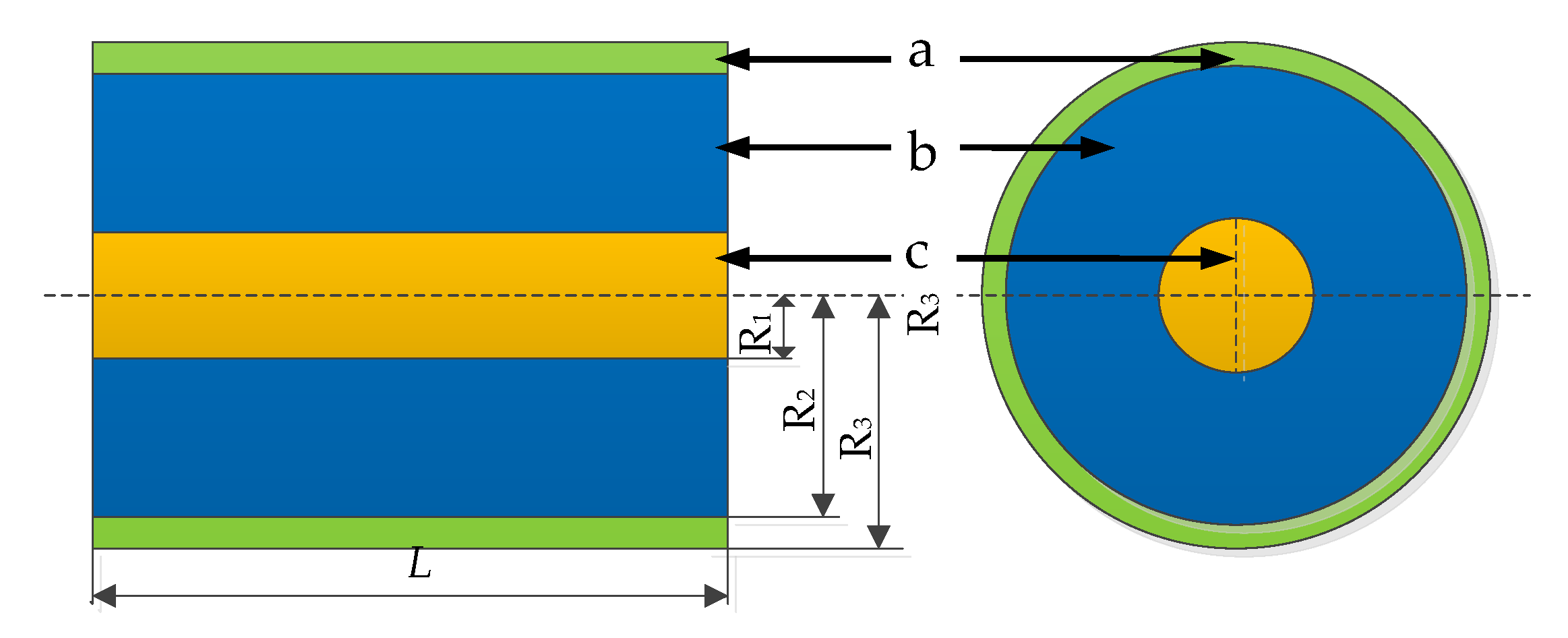
The structural model of a composite boring bar with a constrained layer is shown in Figure 1, wherein L is the overhanging length of boring bar; R1, R2, and R3 are the radii of the base layer, the damping layer, and the constrained layer respectively.
The dynamic modeling of a composite boring bar with a constrained damping layer is shown in Figure 2.
The vibration differential equation of a boring bar with a constraint layer based on the Euler-Bernoulli beam theory can be obtained.
2 x 2 ( ( E I ) equiv 2 y ( x , t ) x 2 ) + ( ρ A ) equiv 2 y ( x , t ) t 2 = f ( x , t ) = Δ F ( t ) δ ( x L )
where y(x,t) is the displacement of the cross-section on the boring bar from the origin o to x at time t; (EI)equiv and (ρA)equiv is the equivalent bending stiffness and surface density of the constrained damping structure, respectively; δ denotes the Dirac delta function; f(x,t) is the distributed force; ∆F(t) is the equivalent concentrated force of f(x,t).
{ ( E I ) equiv = ( E I ) 1 + ( E I ) 2 + ( E I ) 3 ( ρ A ) equiv = ( ρ A ) 1 + ( ρ A ) 2 + ( ρ A ) 3
where (EI)1, (EI)2, and (EI)3 are the bending stiffness of matrix, damping layer, and constraint layer of boring bar, respectively; (ρA)1,(ρA)2, and (ρA)3 denote the surface density of matrix, damping layer, and constraint layer of boring bar, respectively.
The bending stiffness and surface density of the composite matrix are as follows,
{ ( E I ) 1 = π 4 Q ¯ 11 ( r N + 1 4 r 1 4 ) ( ρ A ) 1 = π ρ 1 ( r N + 1 2 r 1 2 )
where Q ¯ 11 is the off-axis stiffness coefficient of composite matrix [20]; rN+1 and r1 are the radii of the Nth layer and the first layer in the matrix layer, respectively; ρ1 is the material density of the matrix layer. Similarly, the bending stiffness and surface density of the damping and constraint layer of boring bar are given by,
{ ( E I ) 2 = π E 2 ( ( 2 R 2 ) 4 ( 2 R 1 ) 4 ) 64 ( ρ A ) 2 = π ρ 2 ( R 2 2 R 1 2 )
{ ( E I ) 3 = π E 3 ( ( 2 R 3 ) 4 ( 2 R 2 ) 4 ) 64 ( ρ A ) 3 = π ρ 3 ( R 3 2 R 2 2 )
where E2 and E3 are the elastic modulus of the damping layer and the constrained layer, respectively; ρ2 and ρ3 are the material density of the damping layer and the constraint layer, respectively.
The main mode shape of the boring bar is expressed as
y ( x , t ) = i = 0 Y i ( x ) sin ( ω t + ϕ ) = i = 0 ( C 1 sin β x + C 2 cos β x + C 3 s h β x + C 4 c h β x ) sin ( ω i t + ϕ )
where C1, C2, C3, C4 and ϕ are constants.
The boring bar is taken to be clamped-free, the boundary conditions for which are
y ( 0 , t ) = 0 , d y ( 0 , t ) d x = 0 , d 2 y ( l , t ) d x 2 = 0 , d 3 y ( l , t ) d x 3 = 0
By substituting Equation (7) into Equation (6), one has
cos β i L c h β i L = 1
Y i ( x ) = cos β i x c h β i x + cos β i L + c h β i L sin β i L s h β i L ( sin β i x s h β i x )
The natural frequency of the boring bar is taken to be
ω i = β i 2 ( E I ) equiv ( ρ A ) equiv
Based on the orthogonal properties of the mode shape function as the equation given by Equation (8), Equation (1) can be converted to Equations (11) and (12).
M i q ¨ i ( t ) + K i q i = f i ( t )
f i ( t ) = 0 L Δ F ( t ) Y i ( x ) δ ( x L ) d x
where Mi and Ki are the i-th modal mass and i-th modal stiffness, respectively. These quantities are given by
M i = 0 L ( ρ A ) e q u i v Y i 2 ( x ) d x
K i = 0 L ( E I ) e q u i v ( Y i ( x ) ) 2 d x
If material damping is considered, and the i-th damping ratio of the structure is set to ξi, then Equation (11) can be changed to
M i q ¨ i ( t ) + 2 ξ i M i K i q ˙ i + K i q i = f i ( t )
According to the theory of vibration mechanics, ξi can be expressed as
ξ i = C 2 M i ω i = η k m 2 M i ω i
where m and k are the mass and static stiffness of the composite boring bar with a constrained damping layer, and η is the structural loss factor of the composite boring bar with constrained damping. k is obtained from
k = 3 ( E I ) equiv L 3 = 3 π ( D 1 4 E 1 + ( D 2 4 D 1 4 ) E 2 + ( D 3 4 D 2 4 ) E 3 ) 64 L 3
where D1, D2, and D3 are the diameter of the matrix, the damping layer, and the constraint layer, respectively.
The structural loss factor η is given as follows
η = α S 1 S 2 1 + ( 2 + S 2 ) S 1 + ( 1 + S 2 ) ( 1 + α 2 ) S 1 2
where α is the loss factor of the damping layer material, S1 is the shear parameter, and S2 is the stiffness parameter. S1 and S2 are given as
S 1 = 1 ( 1 + S 2 ) ( 1 + α 2 )
S 2 = 4 E 3 ( R 3 R 2 ) ( R 3 + R 2 2 ) 3 E 1 R 1 4 + E 3 ( R 3 4 R 2 4 )
According to [11], η is a function of S2 and increases with the increase of S2. Therefore, in order to obtain the best damping effect, the maximum value S2max of the stiffness parameter S2 is needed, when R1 and R3 are known, by deriving S2 from R2 as follows:
d S 2 d R 2 = e R 1 4 ( 2 R 3 3 4 R 2 3 6 R 2 2 R 3 ) + 2 e 2 ( R 3 7 3 R 3 5 R 2 2 + 3 R 2 4 R 3 3 R 3 R 2 6 ) ( R 1 4 + e ( R 1 4 R 2 4 ) ) 2 = 0
where e = E3/E1, and make dS2/dR2 = 0, Equation (21) can be changed into
e R 1 4 ( 2 R 3 3 4 R 2 3 6 R 2 2 R 3 ) + 2 e 2 ( R 3 7 3 R 3 5 R 2 2 + 3 R 2 4 R 3 3 R 3 R 2 6 ) = 0
Through the above formula, R2 corresponding to S2 with maximum S2max can be obtained.
It is assumed that only the influence of cutting depth on cutting force is considered.
Because the cutting force is related to the dynamic cutting depth that depends on the regeneration effect, so Equation (12) can be written as
f i ( t ) = 0 L Δ F ( t ) Y i ( x ) δ ( x L ) d x = K c b Y i ( L ) [ y ( L , t ) y ( L , t T ) ] = K c b Y i 2 ( L ) [ q i ( t ) q i ( t T ) ]
where Kc is the coefficient per unit cutting depth in the feed direction; b is the cutting depth.
Generally, the lower modes are easily excited, and the chatter frequency is slightly higher than the first natural frequency of the system [21]. Therefore, the first frequency of the boring bar is only considered in the analysis. Hence, the dynamic equation of the composite boring bar with the constrained layer damping structure is expressed as
q ¨ 1 ( t ) + 2 ξ 1 ω 1 q ˙ 1 ( t ) + ω 1 2 q 1 ( t ) = K c b Y 1 2 ( L ) ( q 1 ( t ) q 1 ( t T ) ) M 1
Equation (25) is obtained by using Laplace transform on Equation (24)
s 2 + 2 ξ 1 ω 1 s + ω 1 2 = K c b Y 1 2 ( L ) ( 1 e T s ) M 1
Let s = σ ± iω, the value of s depends on the system stability:
  • If σ > 0, the system is unstable;
  • If σ < 0, the system is stable;
  • If σ = 0, the system is under the critical state between stable and unstable.
Let σ = 0, by substituting s = c into Equation (25) after Laplace transform; the following expression can be derived
ω c 2 + 2 ξ 1 ω 1 ω c i + ω 1 2 K c b Y 1 2 ( L ) ( 1 e i T ω c ) M 1 = 0
where ωc denotes the chatter frequency.
According to the Euler formula eix = cos(x) − isin(x), Equation (26) above is expanded and the real part and the imaginary part are separated; therefore, one can get
M 1 ( ω c 2 ω 1 2 ) = K c b Y 1 2 ( L ) ( 1 cos ( T ω c ) )
2 M 1 ξ 1 ω 1 ω c = K c b Y 1 2 ( L ) sin ( T ω c )
Combining Equations (27) and (28), one can get
T ω c = ( 2 j + 1 ) π + 2 arctan ( 2 ξ 1 ω 1 ω c ω c 2 ω 1 2 ) ,   j = 0 , 1 , 2 , 3
where T = 60/n.
The spindle speed n and cutting depth blim are obtained in the critical state of the system, as follows
n = 60 ω c ( 2 j + 1 ) π + 2 arctan ( 2 ξ 1 ω 1 ω c ω c 2 ω 1 2 ) ,   j = 0 , 1 , 2 , 3
b lim = 2 ξ 1 ω 1 ω c K c Y 1 2 ( L ) sin ( 2 arctan ( 2 ξ 1 ω 1 ω c ω c 2 ω 1 2 ) ) 0 L ( ρ A ) equiv Y 1 2 ( x ) d x
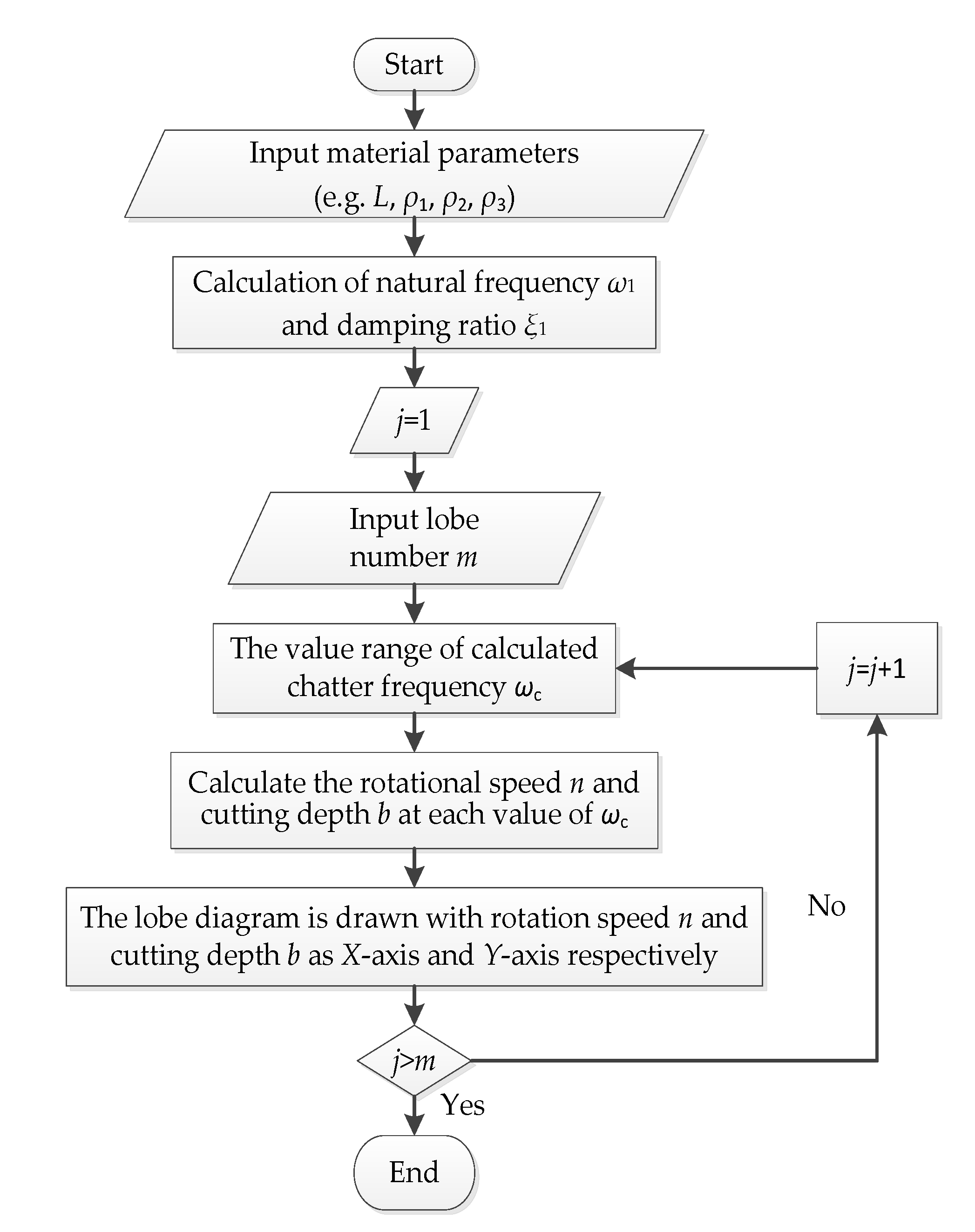
The stability lobes can be calculated by the following steps:
(1)
Determine the material of each layer and geometric parameters of the boring bar;
(2)
Solve the corresponding first-order natural frequency w1 according to Equation (10);
(3)
Scan the chatter frequency wc by using the natural frequency w1 as the reference;
(4)
According to Equation(18), the corresponding structure damping ratio ξi is worked out;
(5)
According to Equations (30) and (31), the spindle speed n and the cutting depth blim under the critical stable state of the system are calculated;
(6)
Select the new j and calculate the adjacent lobes.
The flow chart is shown in Figure 3.

3. Numerical Simulation Results

In this example, the graphite/epoxy resin, carbon/epoxy resin, and steel are selected as the matrix materials, and their mechanical properties are shown in Table 1, Table 2 and Table 3, respectively. The damping layer materials are PMMA, Teflon, and POM, and their mechanical properties are shown in Table 4. It can be seen from [22] that the boring bar corresponding to YG20C is of good cutting stability, and its mechanical properties are shown in Table 5. The composite matrix is paved with 30 layers in the same thickness- in the form of [±θ]30.
The cutting stiffness coefficient per unit cutting thickness is taken as Kc = 2339.1 N/mm2. The relation between the critical cutting width blim and the spindle speed n is drawn by Matlab, according to Equations (30) and (31).
In Figure 3, Figure 4, Figure 5 and Figure 6, the diameter of the matrix and the outer circle of the restraint layer are D1 = 1.5 and D3 = 3 mm, respectively. From Equation (22), D2 = 2.69 mm.

3.1. Effect of Different Base Materials on the Stability of the Boring Bar

Figure 4 displays the relations between the critical cutting width blim and the rotating speed of the spindle n when different base materials were used in the boring bars. The damping layer and the constrained layer of the boring bar were made up of Teflon and YG20C, respectively. To be specific, the ply angle of the composite was set as θ = 0°. As shown in Figure 4a–d, the composite boring bar exhibited greater unconditional and conditional limit cutting depths blim than the metal-boring bar under the same physical sizes and rotating speeds. Meanwhile, the carbon/epoxy boring bar was more stable than the graphite/epoxy boring bar, with more gentle lobe curves. Similarly, with the increasing length-to-diameter ratio, both unconditional and conditional limit cutting depths blim dropped, accompanied by a decline in the rotating speed of the main shaft at the critical stable state. Therefore, when using the boring bar with a larger length-to-diameter ratio, the rotating speed of the main shaft should be higher so as to ensure stability in deep-hole boring.

3.2. Effects of Different Damping Layers on the Stability of the Boring Bar

Figure 5 shows the relationships between the critical cutting width blim and the rotating speed of the spindle n when different damping materials were used in the boring bars. The base layer and the constrained layer were made up of carbon/epoxy and YG20C, respectively. The ply angle of the composite was set as θ = 0°. It can be observed from Figure 5a–d that the Teflon boring bar was superior to the PMMA and POM boring bars with the same geometrical sizes in terms of absolute stable region. By comparing the chattering stability lobe curves, the POM boring bar had the smallest absolute stable region while the Teflon boring bar exhibited gentler curves. However, within a certain velocity range, the unconditional critical cutting depth blim of the POM boring bar was the smallest. The phenomenon remained unchanged with the increase of the length-to-diameter ratio.

3.3. Effect of the Ply Angle of the Base on the Stability of the Boring Bar

Figure 6 displays the relation curves between the critical cutting width blim and the rotating speed of the spindle n when the ply angle of the base is set as different values. The base layer and the constrained layer of the boring bar were made up of carbon/epoxy and YG20C, respectively. With the increasing ply angle θ, the lobe curves moved downward in the coordinate plane, both the unconditional and conditional limit cutting depths decreased, and the unconditional stable region shrank. Meanwhile, the lobe curves became steeper, and the conditional stable region was also narrowed. As the length-to-diameter ratio increased, both the unconditional and conditional cutting depths dropped, while the unconditional stable region expanded.

3.4. The Effect of the Constrained Layer on the Stability of the Boring Bar

For reasonable comparison, it was assumed that the maximum diameter of the boring bar was fixed, and D1, D2, and D3 were set as 1.5, 2.69, and 3 mm in case of the constrained layer, while D1, D2, and D3 were set as 1.5, 3, and 3 mm without the setting of the constrained layer. The base, the damping layer, and the constrained layer of the boring bar were made up of carbon/epoxy, Teflon, and YG20C, respectively. The relation curves between the critical cutting width blim and the rotating speed of the spindle under different conditions were plotted, as the results show in Figure 7. Under the same geometrical size, the stability lobe curves of the boring bar with both a constrained layer and a damping layer were much higher than the curves of the boring bar with only the damping layer, suggesting significantly greater stable region after the addition of the constrained layer. Accordingly, the composite boring bar with the constrained layer can achieve more remarkable cutting stability. The cutting stability can be enhanced by the addition of the constrained layer at an arbitrary length-to-diameter ratio.

3.5. Effect of the Thicknesses of Various Layers on the Stability of the Boring Bar

Finally, by fixing the length-to-diameter ratio of the boring bar at 33.3 (i.e., L/D = 33.3) and changing the thicknesses of various layers, the relation curves between the critical cutting width blim and the rotating speed of the main shaft n under different conditions were plotted, as shown in Figure 8. It should be noted that the base, the damping layer, and the constrained layer of the boring bar were made up of carbon/epoxy, Teflon, and YG20C, respectively, and the ply angle of the composite was set as 0°. To be specific, Figure 8a displays the condition when only the thickness of the base layer changed, from which it can be observed that the cutting stability of the boring bar was improved with the increasing thickness of the base. Figure 8b displays the condition when only the thickness of the damping layer changed, from which it can be observed that the cutting stability of the boring bar was enhanced as the damping layer became thicker. Figure 8c displays the condition when only the thickness of the constrained layer changed, from which it can be observed that the cutting stability of the boring bar was also improved with the increase of the constrained thickness. In Figure 8d, R3 was fixed at 1.5 mm (i.e., R3 = 1.5 mm), and the optimal values of R2 when the value of R1 was set as different values were calculated according to Equation (27). In other words, the thicknesses of the base layer, the damping layer, and the constrained layer were simultaneously changed and the thickness of each layer is listed in Table 6 (H1 = R1, H2 = R2R1, H3 = R3R2).
As shown in Figure 8d, the lobe curve first increased and then dropped with the increase of H1 and H3 and the decrease of H2. When the overall diameter of the boring bar D was fixed, there existed certain optimal thickness ratios among three layers, corresponding to the optimal stability of the boring bar.

4. Analysis and Discussion

4.1. Rigidity Analysis

According to the above analysis, the lobe curves moved downwards with the increasing length-to-diameter ratio of the boring bar, accompanied by a decline in the minimum cutting depth and the increase of the corresponding rotating speed in the stable region. As the length of the boring bar increased, the static rigidity of the boring bar decreased, and the cutter head on the end of the boring bar cannot bear great force to avoid heavy deformation. Therefore, the cutting depth should be set as a low value to ensure safety. When the cutting depth remained unchanged, the required rotating speed of the main shaft in stable cutting decreased with the increase of the length-to-diameter ratio. However, the stable region expanded towards the region with high rotating speed. Accordingly, the conditional cutting depth range expanded with the increase of the rotating speed of the boring bar.
It can also be observed from the lobe curves in Figure 4 that the boring bar with a composite base exhibited a greater cutting depth and a wider stable region than that with a metal base. However, the cutting depths of these boring bars dropped with the increasing length-to-diameter, while the areas of the stable regions increased with the increase of the rotating speed of the spindle. In particular, the carbon fiber/epoxy composite boring bar operated best in stability. According to Equation (31), the minimum cutting depth blim can be calculated. It was found that the minimum cutting depth was in direct proportion to the product of inherent frequency, the damping ratio, and the modal mass. The stability of the composite also depended on the ply angle of the carbon fiber beam. As shown in Figure 6, the stability of the composite dropped with the increasing ply angle, which can be attributed to the established mechanical model of the boring bar based on the Euler-Bernoulli beam theory. The boring bar was only subjected to horizontal force, and the carbon fiber beam can bear great bending stress at a ply angle of 0°. Therefore, only the most stable condition at a ply angle of 0° was selected in this study for calculation.
The minimum cutting depth is related to the related parameters in Equation (31) and the dynamic rigidity during the rotation of the boring bar.
Previous studies have demonstrated that the maximum cutting depth is proportional to the product of the structure’s damping ratio and the static bending rigidity when the angle of the cutting edge and the materials to be processed were the same. In other words, the maximum cutting depth was in direct proportion to the dynamic rigidity.
The dynamic rigidity, denoted as Kd, can be calculated according to Equation (32).
K d = 0.2427 L ξ 1 ω 1 2 ( ρ A ) equiv
Next, the stability characteristics of the boring bar were analyzed from the perspective of dynamic rigidity. Table 7, Table 8, Table 9, and Table 10 list the calculated dynamic rigidities of various boring bars. Through comparison, the dynamic rigidity of the boring bar with the carbon/epoxy base layer was greater than that of the boring bar with the graphite/epoxy base layer. The boring bar using Teflon damping materials also exceeded the boring bars with PMMA and POM damping materials in dynamic rigidity. The dynamic rigidity of the boring bar at a ply angle of 0° was greatest, while the dynamic rigidity of the boring bar at a ply angle of 90° was smallest. After the addition of the constrained layer, the dynamic rigidity of the boring bar was enhanced by 2.8 times, i.e., the boring bar with the constrained layer exhibited better stability. The variation tendencies of the dynamic rigidity in Table 7, Table 8, Table 9, and Table 10 were consistent with the variation rules in Figure 4, Figure 5, Figure 6, Figure 7, and Figure 8. For the composites with greater dynamic rigidity, the lobe curve was slightly higher and the corresponding minimum cutting thickness was greater than those of the composites with smaller dynamic rigidity.

4.2. Estimation of the Optimal Thicknesses of Various Layers

According to the analysis in Section 4.1, the stability of the boring bar is closely related to the change of the dynamic rigidity. Based on the theory of structural loss factor and viscous damping theory of the constrained damping beam, the loss factors is twice of the first-order damping coefficient ξ1, a factor that affects the change of dynamic rigidity.
η = 2ξ1
Substituting Equation (33) into Equation (32), the expression of dynamic stiffness is obtained.
K d = 0.12135 L η ω 1 2 ( ρ A ) equiv
Substitute Equation (18) into Equation (34), and combine Equation (19) to get Equation (35).
K d = 0.12135 L ω 1 2 ( ρ A ) equiv α 1 1 + α 2 1 ( 1 + 2 S 2 ) 1 + S 2
By substituting Equation (20) into Equation (35), the dynamic stiffness related to the geometric dimension of the composite boring, the material parameters, and the vibration characteristics can be expressed.
K d = 0.12135 L ω 1 2 ( ρ A ) equiv α 1 1 + α 2 1 ( 1 + E 1 R 1 4 + E 3 ( R 3 4 R 2 4 ) 2 E 3 ( R 3 R 2 ) ( R 3 + R 2 2 ) 3 ) 1 + 4 E 3 ( R 3 R 2 ) ( R 3 + R 2 2 ) 3 E 1 R 1 4 + E 3 ( R 3 4 R 2 4 )
Through the above analysis, when the maximum size of the boring bar R3 was unchanged, the change ranges of the thicknesses of the base layer and the damping layer (R1 and R2) were determined, i.e., the optimization of the thickness of various layers can be transformed from Equation (22) into solving the optimal value of max{Kd} at the boundary described in Equation (37).
{ 0 R 1 R 3 R 1 R 2 R 3
When the hanging length l of boring bar is 100 mm and the outer diameter R3 is 3 mm, the radii of the base layer and the damping layer in the composite boring bar are calculated as R1 = 0.4828 and R2 = 1.0172 mm, respectively. The optimal thicknesses of various layers can be calculated as H1 = 0.4828, H2 = 0.5344, and H3 = 0.4828 mm. In a proportional format, H1:H2:H3 = 1:1.11:1.
As shown in Figure 9, when the thicknesses of the constrained layer and the damping layer are changed simultaneously, but the sum is fixed, the lobe curves of the chattering stability are different. When the damping layer becomes thicker and the constrained layer becomes thinner, the stability lobe curves first rise and then drop, thereby validating the feasibility of the present optimization method.

5. Conclusions

This study focuses on the chattering stability of the composite boring bar with a constrained damping layer during the boring process. Based on the Euler-Bernoulli beam theory, the regenerative chattering mechanical model of the composite boring bar with a constrained damping layer was established. Using the equivalent bending rigidity, the equivalent surface density, and the damping calculation method of the constrained damping boring bar, the expressions of the critical cutting width blim and the rotating speed of the spindle n were derived. The main conclusions are described below.
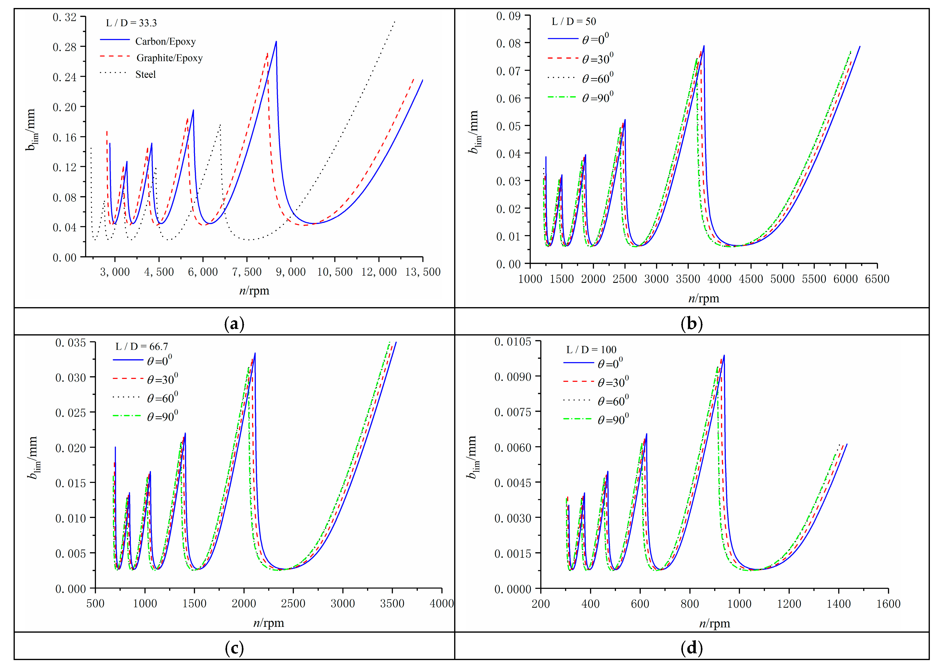
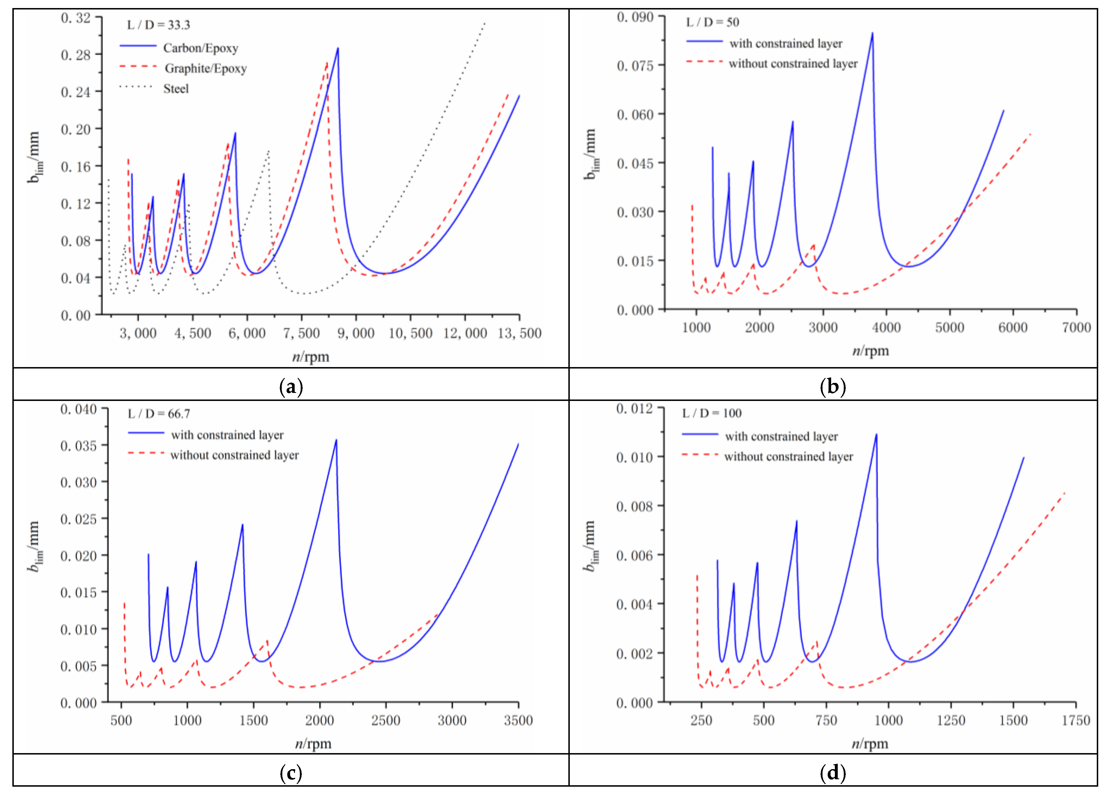
(1) The composite boring bar with a constrained damping layer exhibited a greater limit cutting width than the metal-boring bar. When using the slender boring bar for small and deep-hole processing, the base layer with different materials and thicknesses significantly affected the cutting stability of the boring bar even though the diameter (i.e., the thickness) of the base layer was quite small. The boring bar with the thicker base layer was more stable.
Both the ply angle of the base and the thickness of the constrained layer imposed an obvious effect on the cutting stability of the composite boring bar. The boring bar with the constrained layer was stable at a ply angle of 0°.
(2) The material of the damping layer was also the main factor that affected the stability of the composite boring bar. The material of the damping layer significantly affected the cutting stability of the boring bar, even when the diameter of the damping layer was fairly small.
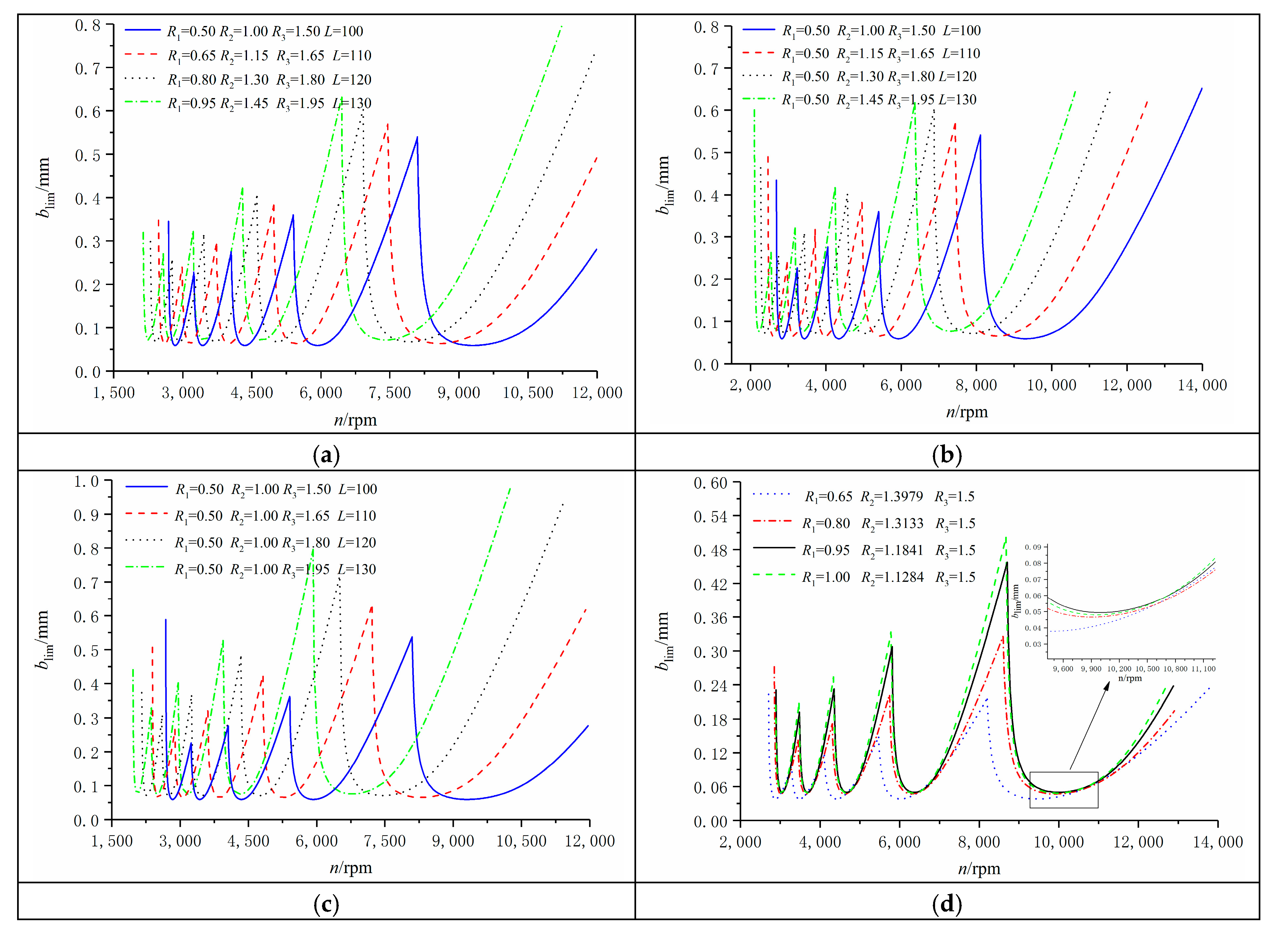
(3) When various materials and the overall geometrical size of the constrained damping composite boring bar were unchanged, the stability of the boring bar first increased and then dropped with the increasing thicknesses of various layers. Accordingly, there exists an optimal thickness proportion of the thicknesses of various layers in the composite boring bar so as to reach the most favorable stability.
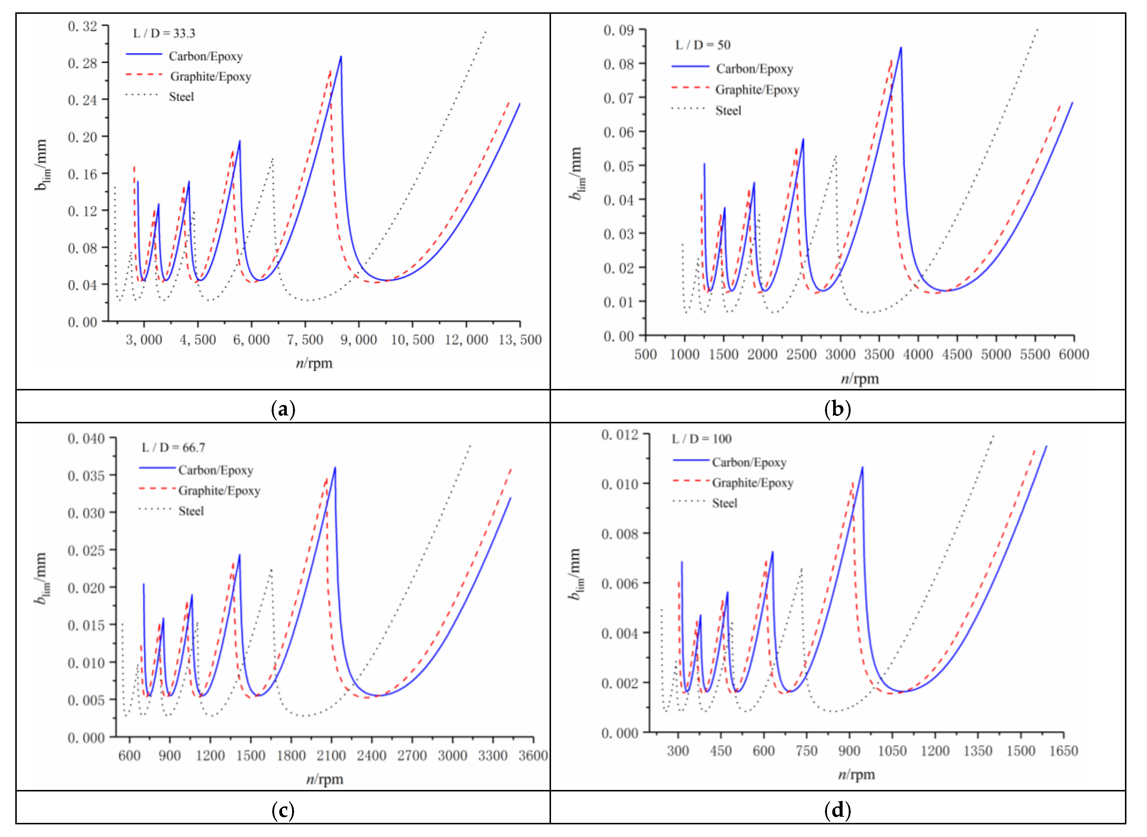
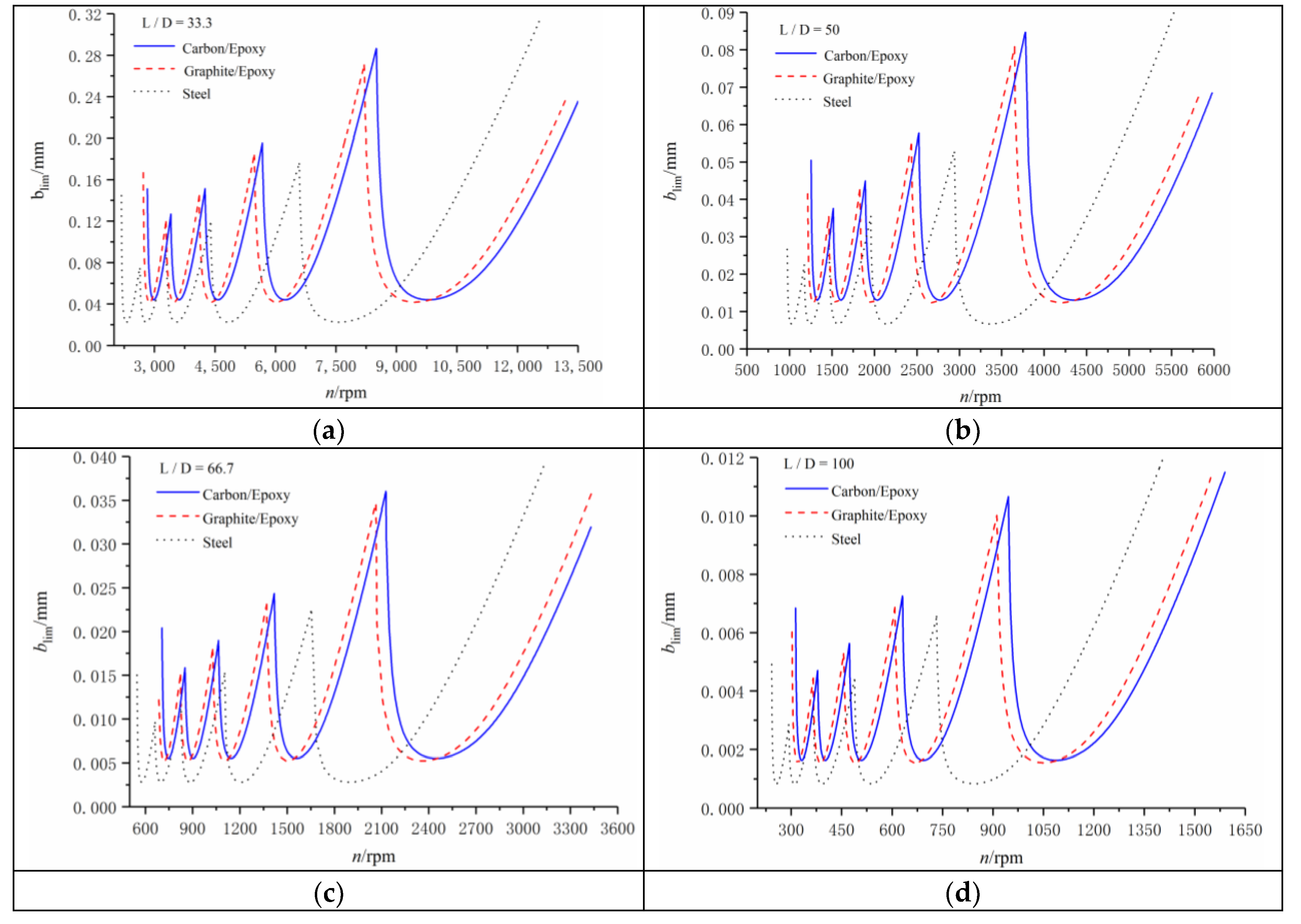
(4) When using the boring bar with a large diameter-to-length ratio for deep-hole boring, the rotating speed of the spindle and the unconditional cutting depth should be set as low values to ensure boring stability. Meanwhile, the conditional cutting depth increased. Furthermore, the above conclusions were still applicable to the increasing length-to-diameter ratio.
This work is part of a project that focuses on the study of chatter stability in cutting processes with a composite tooling system. The experimental verification of the presented model using real boring bars will be the subject of a study in the future.
See Table A1 for the important parameters in the paper.

Author Contributions

Y.R. proposed the main idea and the validation method; J.Z. and H.W. derived the equations in the model, coded the computer program, and obtained the calculations; W.H. wrote the manuscript and drew the figures; C.F. and C.Z. helped perform the analysis with constructive discussions. All authors have read and agreed to the published version of the manuscript.

Funding

This work was supported by the National Natural Science Foundation of China (Grant No.11672166), and China Postdoctoral Science Foundation Funded Project (Grant No.2016M5922165).

Conflicts of Interest

The authors declare that there is no conflict of interest regarding the publication of this paper.

Appendix A. Variable Comment Table

Table A1. Important parameter annotation table.
VariableNote
y(x,t)The displacement of the cross-section on the boring bar from the origin o to x at time t
Yi(x)The i-th mode function
(EI)equivThe equivalent bending stiffness
variablenote
(ρA)equivThe equivalent surface density
variablenote
R1 The radius of base layer
R3The radius of constrained layer
ξiThe i-th damping ratio
S2The stiffness parameter
F(t)The equivalent concentrated force of f(x,t)
αThe loss factor of the damping layer material
LThe overhanging length of boring bar
δThe Dirac delta function
kThe static stiffness
variablenote
η The structural loss factor
variablenote
R2The radius of damping layer
KcCutting force coefficient
S1The shear parameter
f(x,t)The distributed force
ωiThe i-th natural frequency

References

  1. Wang, L.P.; Yang, S.Z.; Yang, Z.J. Research situation and development trend of vibration drilling at home and abroad. Mach. Des. Manuf. Eng. 1999, 28, 1–4. [Google Scholar]
  2. Andren, L.; Hakansson, L.; Brandt, A. Identification of dynamic properties of boring bar vibrations in a continuous boring operation. Mech. Syst. Signal. Process. 2004, 18, 869–901. [Google Scholar] [CrossRef] [Green Version]
  3. Lee, D.G.; Hwang, H.Y.; Kim, J.K. Design and manufacture of a carbon fiber epoxy rotating boring bar. Compos. Struct. 2003, 60, 115–124. [Google Scholar] [CrossRef]
  4. Wang, J.; Wu, F.H.; Han, Y.L. Boring bar design with laminar composite structure and research on properties. Chin. Mech. Eng. 2013, 24, 711–715. [Google Scholar]
  5. Jing, Q.W.; Guo, Z.; Li, C.S. Calculation of the model of novel anti-vibration composite boring bar with ABAQUS. J. Mater. Met. 2013, 12, 217–330. [Google Scholar]
  6. Wu, N.Z.; Zhou, L.P. Mathematical model and finite element analysis for a new type of boring bar made of composite materials. J. Xihua Univ. 2005, 24, 22–25. [Google Scholar]
  7. Wang, M.; Qu, B.X.; Zan, T. A Boring Bar Structure Based on Friction Damping. Patent CN101508029, 19 August 2009. [Google Scholar]
  8. Edhi, E.; Hoshi, T. Stabilization of high frequency chatter vibration in fine boring by friction damper. Precis. Eng. 2001, 25, 224–234. [Google Scholar] [CrossRef]
  9. Du, J.X. Study on Theory and Experiments for Damping Tools with High Slenderness Ratio. Master’s Thesis, North University of China, Taiyuan, China, 2013. [Google Scholar]
  10. Moradi, H.; Bakhtiari, N.F.; Movahhedy, M.R. Tuneable vibration absorber design to suppress vibrations: An application in boring manufacturing process. J. Sound Vib. 2008, 318, 93–108. [Google Scholar] [CrossRef]
  11. Xie, F.; Wang, W.X.; Lei, X.B. Design and simulation of flat boring bar with two material combination structures. J. Syst. Simul. 2017, 29, 1290–1296. [Google Scholar]
  12. He, M. Dynamic Characteristics Analysis and Optimization Design of Dynamic Damping Boring Bar. Master’s Thesis, Southeast University, Nanjing, China, 2018. [Google Scholar]
  13. Kang, W. The Design and Performance Analysis of Boring Bar with 2-DOF Dynamic Vibration Absorber. Master’s Thesis, Yanshan University, Qinhuangdao, China, 2013. [Google Scholar]
  14. He, J.S. Dynamic analysis of boring bar with laminated damping. Trans. Nonferrous Met. Soc. China 1995, 5, 144–148. [Google Scholar]
  15. Li, H.J. The Design of Composite Damping Boring Bar. Master’s Thesis, Yanshan University, Qinhuangdao, China, 2008. [Google Scholar]
  16. Xia, F. Development of Constrained Damping Boring Bar. Master’s Thesis, Shandong University, Jinan, China, 2014. [Google Scholar]
  17. Tan, J.; Fang, H.; Zhao, Q.J. Trial-produce and vibration reduction performance analysis of built-in damping boring bar. Mod. Manuf. Eng. 2019, 3, 86–91. [Google Scholar]
  18. Meng, F.C.; Guan, S.X.; Wang, Z.Z. Study on suppression of deep hole boring chatter by thin hole damping. Tool Eng. 2018, 52, 68–72. [Google Scholar]
  19. Biju, C.V.; Shunmugam, M.S. Investigation into effect of particle impact damping (PID) on surface topography in boring operation. Int. J. Adv. Manuf. Technol. 2014, 75, 1219–1231. [Google Scholar] [CrossRef]
  20. Ren, Y.S.; Du, X.S.; Sun, S.S. Structural damping of thin-walled composite one-cell beams. J. Vib. Shock 2012, 31, 141–146. [Google Scholar]
  21. Tobias, S.A. Vibration of Machine Tools; Translated by Department of Mechanical Manufacturing Tianjin University; China Machine Press: Beijing, China, 1977; pp. 203–205. [Google Scholar]
  22. Tian, J.S. Analysis Prediction of Regenerative Chatter Stability for Passive Constrained Damping Layer Composite. Master’s Thesis, Shandong University of Science and Technology, Qingdao, China, 2018. [Google Scholar]
  23. Saravanos, D.A.; Varelis, D.; Plagianakos, T.S. A shear beam finite element for the damping analysis of tubular laminated composite beam. J. Sound Vib. 2006, 291, 802–823. [Google Scholar] [CrossRef]
  24. Sino, R.; Baranger, T.N.; Chatelet, E.; Jacque, T.G. Dynamic analysis of a rotating composite shaft. Compos. Sci.Technol. 2008, 68, 337–345. [Google Scholar] [CrossRef] [Green Version]
  25. Akoussan, K.; Boudaoud, H.; Daya, E.M. Vibration modeling of multilayer compositestructures with viscoelastic layers. Mech. Adv. Mater. Struct. 2015, 22, 136–149. [Google Scholar] [CrossRef]
  26. Bhimaraddi, A. Sandwich beam theory and the analysis of constrained layer damping. J. Sound Vib. 1995, 179, 591–602. [Google Scholar] [CrossRef]
  27. Liu, Y.; Liu, Z.Q.; Song, Q.H. Optimization and damping performance of constrained damping boring bar. Chin. J. Aeronaut. 2016, 376, 1992–2002. [Google Scholar]
Figure 1. Structure diagram of the boring bar of composite material with damping of the constrained layer. (a) The constrained layer; (b) the damping layer; (c) the base layer.
Applsci 10 04537 g001
Figure 2. Dynamic model of a boring rod of composite material with damping of the constrained layer.
Applsci 10 04537 g002
Figure 3. Flow chart of algorithm.
Applsci 10 04537 g003
Figure 4. Relations between the critical cutting width blim and the rotating speed of the spindle n with respect to different base materials used, in which L denotes the length and L/D denotes the length-to-diameter of the boring bar, respectively, (a) L = 100 mm and L/D = 33.3, (b) L = 150 mm and L/D = 50, (c) L = 200 mm and L/D = 66.7, and (d) L = 300 mm and L/D = 100.
Applsci 10 04537 g004
Figure 5. Relations between the critical cutting width blim and the rotating speed of the spindle n with respect to different damping materials used, in which L denotes the length and L/D denotes the length-to-diameter of the boring bar, respectively, (a) L = 100 mm and L/D = 33.3, (b) L = 150 mm and L/D = 50, (c) L = 200 mm and L/D = 66.7, and (d) L = 300 mm and L/D = 100.
Applsci 10 04537 g005
Figure 6. Relationships between the critical cutting width blim and the rotating speed of the spindle n when the ply angle of the base was set as different values, in which L denotes the length and L/D denotes the length-to-diameter of the boring bar, respectively, (a) L = 100 mm and L/D = 33.3, (b) L = 150 mm and L/D = 50, (c) L = 200 mm and L/D = 66.7 and (d) L = 300 mm and L/D = 100.
Applsci 10 04537 g006
Figure 7. Relationships between the critical cutting width blim and the rotating speed of the spindle n, with or without constrained layer, in which L denotes the length and L/D denotes the length-to-diameter of the boring bar, respectively. (a) L = 100 mm and L/D = 33.3, (b) L = 150 mm and L/D = 50, (c) L = 200 mm and L/D = 66.7, and (d) L = 300 mm and L/D = 100.
Applsci 10 04537 g007
Figure 8. The influence of the diameter (thickness) of each material layer on the chatter stability of the boring bar. (a) The change of thickness for the substrate layer, (b) The change of thickness for the damping layer, (c) The change of thickness for the constrained layer, and (d) The optimal thickness of the damping layer.
Applsci 10 04537 g008
Figure 9. Influence of the thickness of the restraint layer and the damping layer on chatter stability.
Applsci 10 04537 g009
Table 1. Mechanical properties of graphite/epoxy resin [23].
ρ(kg/m3)E11(GPa)E22(GPa)G12(GPa)G23(GPa)ν12η1(%)η2(%)η4(%)η5 = η6(%)
167225.88.73.53.50.340.652.342.892.89
Table 2. Mechanical properties of carbon/epoxy resin [24].
ρ(kg/m3)E11(GPa)E22(GPa)G12(GPa)G23(GPa)ν12η1(%)η2(%)η4(%)η5 = η6(%)
1446.2172.77.23.763.760.30.454.227.057.05
Table 3. Mechanical properties of steel.
ρ(kg/m3)E(GPa)G(GPa)ν
768020779.60.3
Table 4. Mechanical properties of viscoelastic materials [3,25,26].
NumbersMaterialsρ(kg/m3)E(GPa)Gv(GPa)αν
1PMMA11801010.10.3
2Teflon22800.50.260.050.4
3POM142026100.10.39
Table 5. Mechanical properties of constraint layer materials [27].
Materialsρ(kg/m3)E(GPa)ν
YG20C13,4004000.3
Table 6. The value of thickness corresponding to each layer.
H1(mm) H2(mm) H3(mm)
0.650.747970.1021
0.80.51330.1867
0.950.23410.3159
10.12840.3716
Table 7. The dynamic characteristics of different matrix materials.
MaterialsL(m)ξ1ω1 (rad/s)(ρA)equiv(kg)Kd(N/m)
Carbon/Epoxy0.10.0245281756.20.026648.8185
Graphite/Epoxy0.10.023571694.80.027044.3639
Table 8. The dynamic characteristics of damping materials.
MaterialsL(m)ξ1ω1 (rad/s)(ρA)equiv(kg)Kd(N/m)
PMMA0.10.0245181737.30.025746.1570
Teflon0.10.0245281756.20.026648.8185
POM0.10.012281578.80.030022.2866
Table 9. The dynamic characteristics of ply angles.
θL(m)ξ1ω1 (rad/s)(ρA)equiv(kg)Kd(N/m)
0.10.0245281756.20.026648.8185
30°0.10.0245531732.40.026647.5721
60°0.10.0245831704.50.026646.1084
90°0.10.0245871700.60.026645.9051
Table 10. The dynamic characteristics with and without constraint layer.
L(m)ξ1ω1 (rad/s)(ρA)equiv(kg)Kd(N/m)
with constraint layer 0.10.0245281756.20.026648.8185
without constraint layer0.10.0414781310.10.010117.4509

