Article

A Strain-Transfer Model of Surface-Bonded Sapphire-Derived Fiber Bragg Grating Sensors

1
School of Instrumentation Science and Opto-electronics Engineering, Beihang University, Xueyuan Road No. 37, Haidian District, Beijing 100191, China
2
Changcheng Institute of Metrology and Measurement, Huanshan Village, Wenquan Town, Haidian District, Beijing 100095, China
3
School of Mechatronics Engineering, Henan University of Science and Technology, Xiyuan Road No. 48, Jianxi District, Luoyang 471000, Henan Province, China
*
Author to whom correspondence should be addressed.
Appl. Sci. 2020, 10(12), 4399; https://doi.org/10.3390/app10124399
Submission received: 12 June 2020 / Revised: 22 June 2020 / Accepted: 23 June 2020 / Published: 26 June 2020
(This article belongs to the Section Optics and Lasers)

Abstract

:
An improved strain-transfer model was developed for surface-bonded sapphire-derived fiber Bragg grating sensors. In the model, the core and cladding of the fiber are separated into individual layers, unlike in conventional treatment that regards the fiber as a unitive structure. The separation is because large shear deformation occurs in the cladding when the core of the sapphire-derived fiber is heavily doped with alumina, a material with a high Young’s modulus. Thus, the model was established to have four layers, namely, a core, a cladding, an adhesive, and a host material. A three-layer model could also be obtained from the regressed four-layer model when the core’s radius increased to that of the cladding, which treated the fiber as if it were still homogeneous material. The accuracy of both the four- and three-layer models was verified using a finite-element model and a tensile-strain experiment. Experiment results indicated that a larger core diameter and a higher alumina content resulted in a lower average strain-transfer rate. Error percentages were less than 1.8% when the four- and three-layer models were used to predict the transfer rates of sensors with high and low alumina content, respectively.

1. Introduction

Fiber-optic strain, twist, and torsion sensors have played an important role in structural-integrity monitoring because their compact size, light weight, and immunity to electromagnetic interference represent significant advantages [1,2,3,4,5,6,7]. Between these, strain sensors are generally embedded into or bonded to the surface of the host material. The strain on the host material transfers to fiber sensors through adhesive and polymeric coating, and is then measured by the sensitive structure in the fiber core. Unfortunately, strain loss inevitably occurs in the transfer process because of shear deformation of the intermedium between fiber and host material. Thus, strain-transfer theory was developed to describe the actual strain-transfer process [8,9,10,11,12,13,14,15,16,17,18,19,20,21,22,23]. In the case of embedded strain sensors, an analytical model based on force equilibrium and compatibility was developed to present the real strain on the host material on the basis of a number of realistic assumptions, such as materials behaving in a linear elastic manner, and the existence of a perfect bond [8]. The multilayer-interface strain-transfer mechanism is usually analyzed using simplified geometrical and physical functions [9]. The transfer model was improved by considering the influence of the sensor on strain distribution in the host material [10]. Strain-transfer analysis was conducted with the viscoelastic properties of the host material considered to describe the interfacial shear–stress relationship [16]. To investigate the interfacial-failure mechanism, the strain-transfer model was also extended to diagnose local interfacial debonding [18]. In the case of surface-bonded sensors, various stacking parameters of carbon-fiber-reinforced polymer laminates were analyzed by establishing a finite-element (FE) model [20]. The sensor was tested under fatigue load to derive the transfer formula in response to dynamic strain [23]. A strain-transfer model was also presented to study the influence of coating [24]. However, the above models were all based on the common single-mode fiber, and are probably not suitable for strain sensors containing sapphire-derived fibers (SDFs). The SDF is a specific fiber with an alumina dopant in the fiber core [25], and the sapphire-derived fiber Bragg grating (SDFBG) showed potential for strain measurement in temperatures as high as 950 °C [26,27,28,29]. The Young’s modulus of alumina (about 500 GPa) is much higher than that of silica (about 72 GPa); therefore, deformation resistance of a core with a high alumina content is much higher than that of pure silica cladding, leading to the shear deformation of the cladding and strain loss. Although many investigations were conducted on the strain-transferring mechanism between optic fiber and host material, they were all based on the assumption that the fiber possessed an approximately homogeneous elastic property, which is probably reasonable because both the core and cladding of the fiber are mainly made of silica. The pure silica approximation, however, could not be used in our case because of the alumina dopant in the core of the SDF. Therefore, the application of traditional strain-transfer models is quite limited in SDFBG-based strain measurement.
In this paper, an improved four-layer strain-transfer model for surface-bonded SDFBG sensors was theoretically developed and experimentally demonstrated. The four layers were a core, cladding, an adhesive, and a host material, and the cladding was analyzed as an individual layer of the medium in order to reflect strain loss. When the core’s radius increased to that of the cladding, however, the cladding layer disappeared, and the four-layer model regressed to a three-layer model. The FE model and the static-tensile-strain experiment were conducted using a universal testing machine to verify both the four- and three-layer models. Good agreement was achieved between theoretical predictions and experiment results. A larger core diameter and a higher alumina content led to a lower strain-transfer rate. Errors (less than 2%) were obtained when the four- and three-layer models were used to predict the average strain-transfer rate (ASTR) of SDFBGs with high and low alumina content, respectively.

2. Theoretical Approach

The four-layer sensing model for the surface-bonded SDFBG test system had a core, cladding, an adhesive, and a host material, and the grating was located in the center of the core, as shown in Figure 1. The homocentric cylindrical optic-fiber cladding and core were mounted on the host material, with the adhesive filled in between the two. When the core’s radius increased to that of the cladding, the cladding layer disappeared, and the four-layer model regressed to a three-layer model that only had a core, an adhesive, and a host material, as shown in Figure 2. Like traditional models [8,11,20,22], the three-layer model treated the core and cladding as essentially the same homogeneous material. The stress state in the four-layer model is presented in Figure 3. Some assumptions were made before the analytical model could be built:
1)
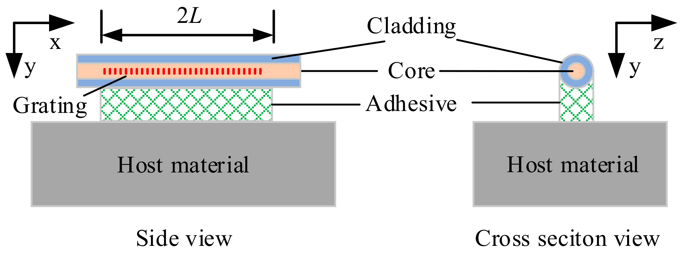
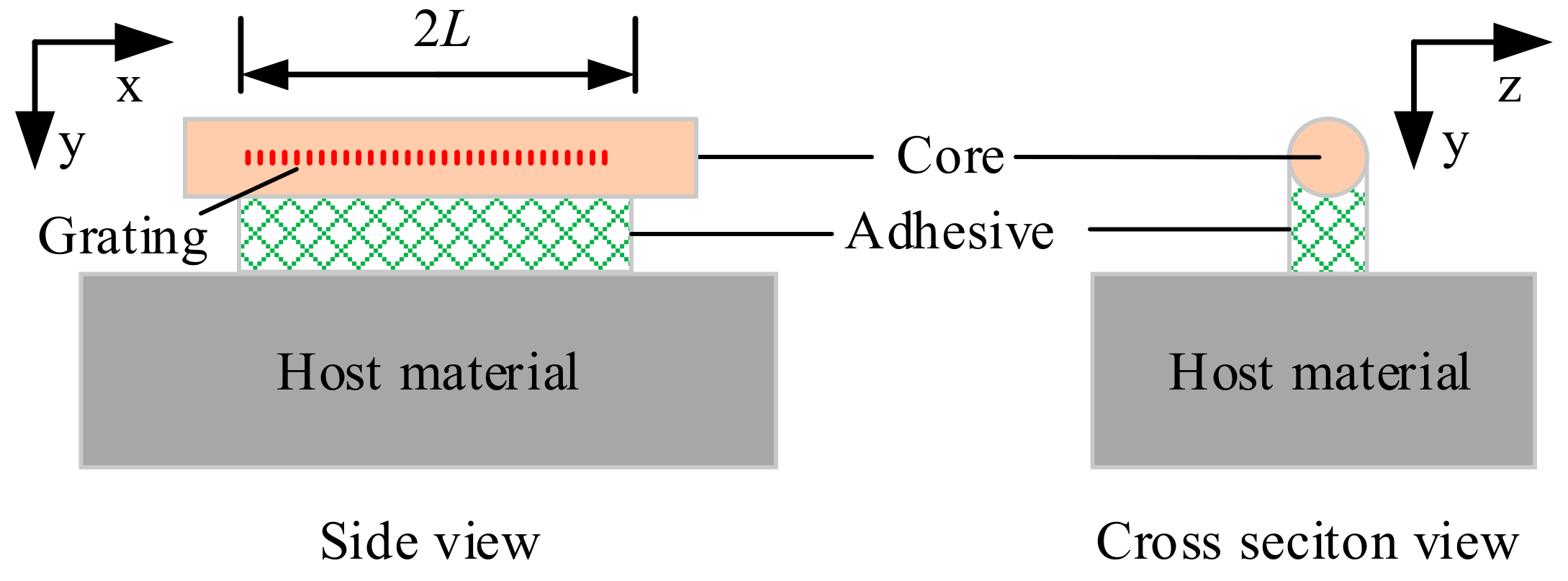
The SDF core, cladding, adhesive layer, and monitored substrate were to be made of linear, elastic, homogeneous materials.
2)
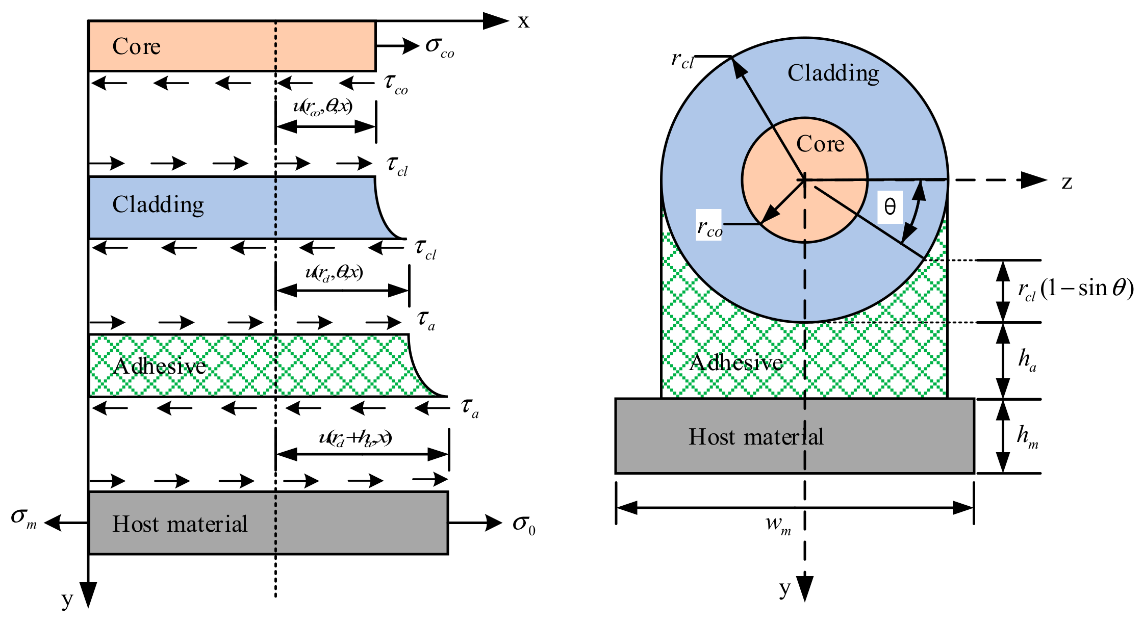
The adhesive layer was to be closely bonded to the SDF and substrate materials, with no relative slip. Shear stress and displacement at the interface between the two different media were to be at the same amplitude.
3)
Both the adhesive layer and the cladding layer were to only be subject to shear strain. This is because the Young’s modulus of the adhesive layer and the cladding layer would be much smaller than that of the heavily doped alumina core and the substrate material.
In this model, subscripts co, cl, a, and m represent core, cladding, adhesive, and host material, respectively. τ , σ , ε , and γ are shear stress, normal stress, shear strain, and normal strain, respectively; G and E represent shear modulus and Young’s modulus; and r , L , h , θ , and w are radius, half-bond length of the adhesive, height, angle, and width, respectively.
The Young’s modulus of the SDF core was determined by its alumina content, and it could be expressed as percentage m of its volume in the Al2O3–SiO2 binary system. Thus, by using the addition model [30], the Young’s modulus of the core could be calculated as
E c o = m E A l 2 O 3 + ( 1 m ) E S i O 2 ,
where E A l 2 O 3 and E S i O 2 are the Young’s moduli of alumina and silica, respectively.
As shown in Figure 3, difference in the displacement along the optic-fiber axis (x- co-ordinate axis) between the core–cladding and the cladding–adhesive interfaces could be described as
u ( r c l , θ , x ) u ( r c o , θ , x ) = r c o r c l γ c l ( r , θ , x ) d r = 1 G c l r c o r c l τ c l ( r , θ , x ) d r
According to Assumption 2, shear stresses at the interface between core and cladding are equal in amplitude, namely, τ c l ( r c o , θ , x ) = τ c o ( r c o , θ , x ) . Shear stresses in the cladding were assumed to be inverse to the radius, and could be given by
τ c l ( r , θ , x ) = τ c l ( r c o , θ , x ) r c o r = τ c o ( r c o , θ , x ) r c o r .
According to Her and Huang [24], displacement continuity at the interface between cladding and core could be derived from Equation (2) using the stress relationship in Equation (3), and given as
u c l ( r c l , θ , x ) = u a ( r c l , θ , x ) = r c l G c l · ln r c l r c o · τ ( r c l , θ , x ) + u c o ( r c o , θ , x ) ,
where u c o ( r c l , θ , x ) can be replaced with u c o ( r c l , x ) because the displacement of the core was regarded as independent from the angle.
The shear strain of the adhesive is defined as
τ a ( r c l , θ , x ) = γ a · G a = u m ( r c l + h a , x ) u a ( r c l , θ , x ) r c l ( 1 sin θ ) + h a · G a .
When Equation (4) is substituted into Equation (5), the shear stress of the cladding can be rewritten as
τ c l ( r c l , θ , x ) = u m ( r c l + r a , x ) u c o ( r c o , x ) r c l ( 1 sin θ ) + h a G a + r c l G c l ln r c l r c o .
The equilibrium equation for the cladding is
r c l · 0 π τ c l ( r c l , θ , x ) d θ · d x r c o · 0 2 π τ c l ( r c o , θ , x ) d θ · d x = 0 .
Substituting Equation (6) into Equation (7) yields
0 2 π τ c l ( r c o , θ , x ) d θ = r c l r c o 0 π u m ( r c l + r a , x ) u c o ( r c o , x ) r c l ( 1 sin θ ) + h a G a + r c l G p ln r c l r c o d θ .
The equilibrium equation for the core is
d σ c o · π r c o 2 + r c o · 0 2 π τ c o ( r c o , θ , x ) d θ · d x = 0 .
By deriving Equation (9) for x and incorporating it into Equation (8), we obtain
d 2 σ c o d x 2 + r c l π r c o 2 ( σ m E m σ c o E c o ) 0 π 1 r c l ( 1 sin θ ) + h a G a + r c l G c l ln r c l r c o d θ
The equilibrium equation for the four-layer structure can be expressed as
π r c o 2 σ c o = ( σ 0 σ m ) w m h m .
Substituting Equation (11) into Equation (10) yields
d 2 σ c o d x 2 k 2 σ c o E c o = k 2 π r c o 2 w m h m + E m E c o σ 0 ,
where
k = 1 π r c o π r c o 2 w h m 1 E m + 1 E c o 0 π 1 r c l ( 1 sin θ ) + h a G a + r c o G c l ln r c l r c o d θ
The general solution for the differential of Equation (12) can be given as
σ c o = c 1 sinh k x + c 2 cosh ( k x ) + k 2 π r c o 2 w h c l + E m E c o σ 0 ,
where constant coefficients c 1 and c 2 are determined by the following boundary conditions at the ends of the core:
σ c o ( ± L ) = 0 .
Therefore, stress on the optical fiber could be obtained through the following equation:
σ c o = σ 0 π r c o 2 w h c l + E m E c o 1 cosh ( k x ) cosh ( L x )
Substituting stress–strain relationships σ c o = ε c o E c o and σ 0 = ε 0 E m into Equation (12) yields
ε c o ε 0 = 1 1 + π r c o 2 w h c l E c o E m 1 cosh ( k x ) cosh ( L x ) .
The ASTR is defined as
T = 1 2 L L L 1 1 + π r c o 2 w h c l E c o E m 1 cosh ( k x ) cosh ( L x ) d x .

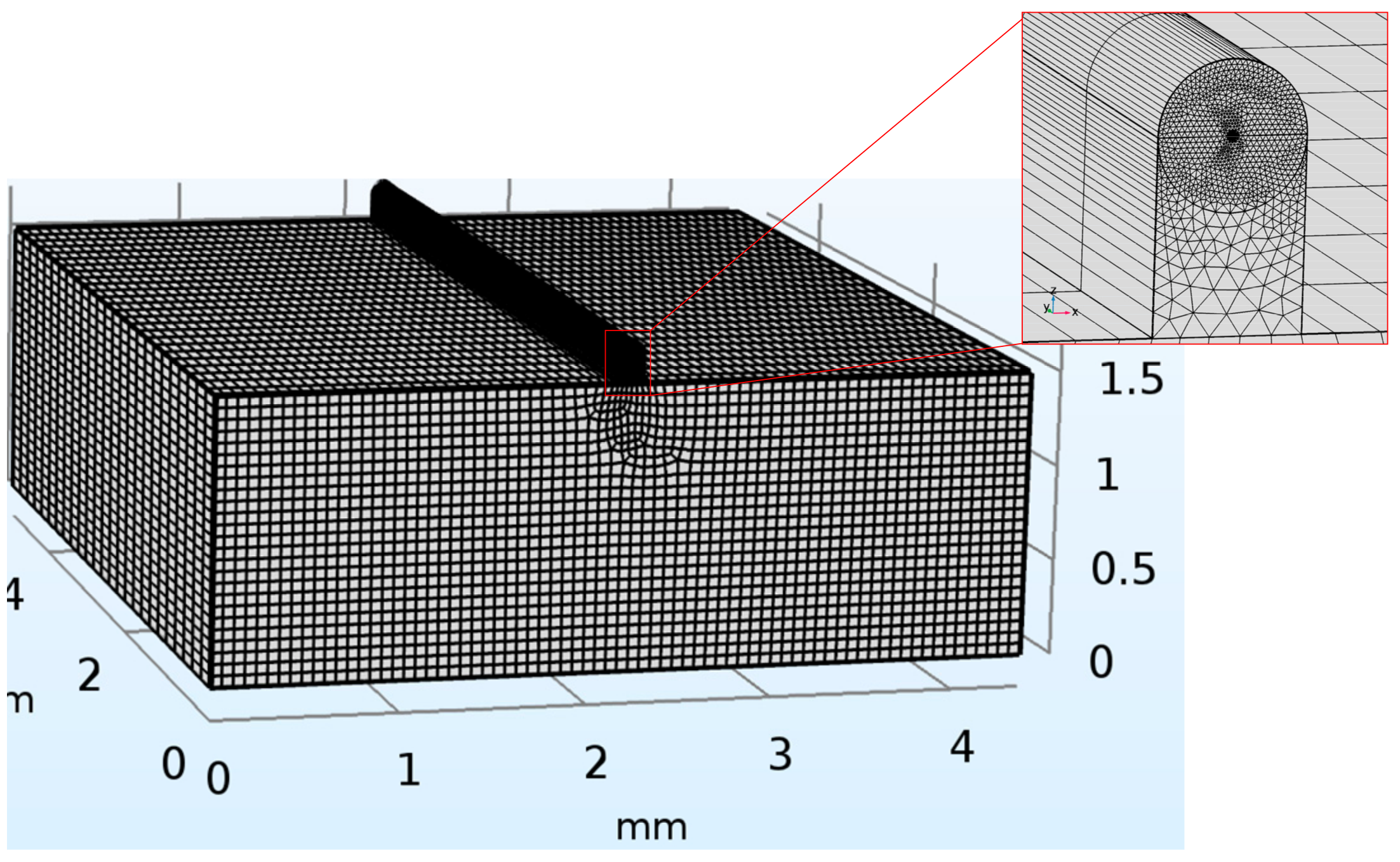
3. Finite Element Analysis

The FE model is usually generated to validate analytical models. Unlike in previous studies [10,22,31] that mainly focused on the strain-transfer medium except for the fiber, the FE simulation in this section was used to study the effects of an alumina dopant in the fiber core. In order to obtain the appropriate adhesive size for the FE model, however, the half-bond length and the bottom thickness of the adhesive layer had to first be analyzed using the three-layer model ( r c o = r c l in Equation (14) with no alumina dopant (m = 0)). The relevant physical characteristics of the materials and the size of each layer are listed in Table 1 and Table 2, respectively. Results are shown in Figure 4. A half-bond length of L = 5 mm and a bottom thickness of h a = 0.1 mm were selected, as a relatively high ASTR (over 90%) had been obtained in these conditions. The FE model was then established using COMSOL Multiphysics 5.3 (COMSOL Co., Ltd., Stockholm, Sweden) commercial software. Mesh generation is shown in Figure 5.
The influence of the fiber core’s radius and alumina content on the ASTR was studied. Figure 6 shows the simulated results calculated from both the analytical four-layer model and the FE model. When the core’s radius increased to the cladding’s radius (62.5 μm), the ASTRs of the four-layer model for different alumina contents were approximately equal to the corresponding rates from the three-layer model (see black rectangle in Figure 6). Simulated results indicated that ASTRs generally experienced a decreasing trend as the core’s radius increased from 5 to 62.5 μm. For example, when the alumina content was 50 mol %, ASTRs from the four-layer and FE models decreased from 97.2% to 77.6% and 92.1% to 76.4%, respectively. This could mainly be attributed to two factors. First, cladding thickness decreased with the core’s increasing radius, which was beneficial to the efficient transfer of strain from the adhesive to the core. Second, increasing radius reduced the normal stress on the cross section of the core because normal stress is approximately inversely proportional to the core’s radius, as shown in Equation (11). Although both factors mitigated each other, the latter was proven to be stronger, which led the ASTR to decrease with the core’s increasing radius. In addition, increasing alumina content also led to a decrease in ASTRs. When the core’s radius was fixed at a certain value, such as 30 μm, ASTRs from the four-layer and FE models decreased from 95.3% to 84.1% and 91.5% to 85.9%, respectively. Significant strain loss resulted from large shear deformation that occurred in cladding.
Errors of the four- and three-layer models from the FE model are shown in Figure 7. For the cases where there was no- and low-alumina content (m = 0 mol % and m = 4 mol %), the three-layer model achieved smaller error percentages than those of the four-layer model. This was reasonable because the three-layer model assumed homogeneous material within the fiber region, which was consistent with the fact that the fiber was still mainly composed of silica. Therefore, the three-layer model was more suitable than the four-layer model for predicting transfer efficiency when there was no or low alumina dopant in the core. For cases of high alumina content (m = 50 mol % and m = 100 mol %), however, error percentages of the four-layer model from the FE model were significantly smaller than those of the three-layer model. The change in errors indicated that the core and cladding needed to be treated as separate layers instead of a unit because the Young’s modulus of the alumina/silica core was much higher than that of the silica cladding. As a result, the four-layer model was a better choice than the three-layer model to predict ASTR for the fiber with high alumina content.

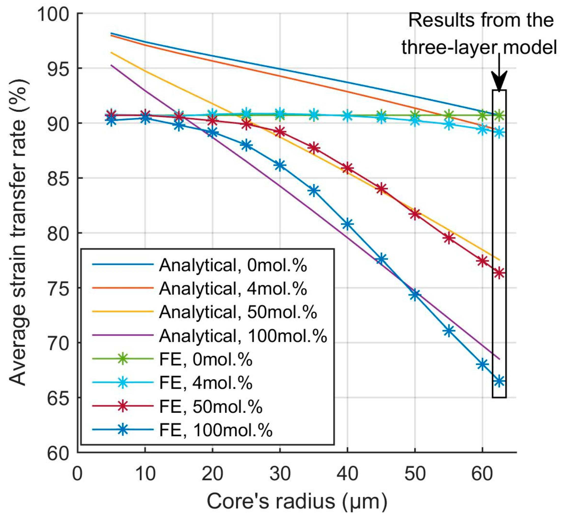
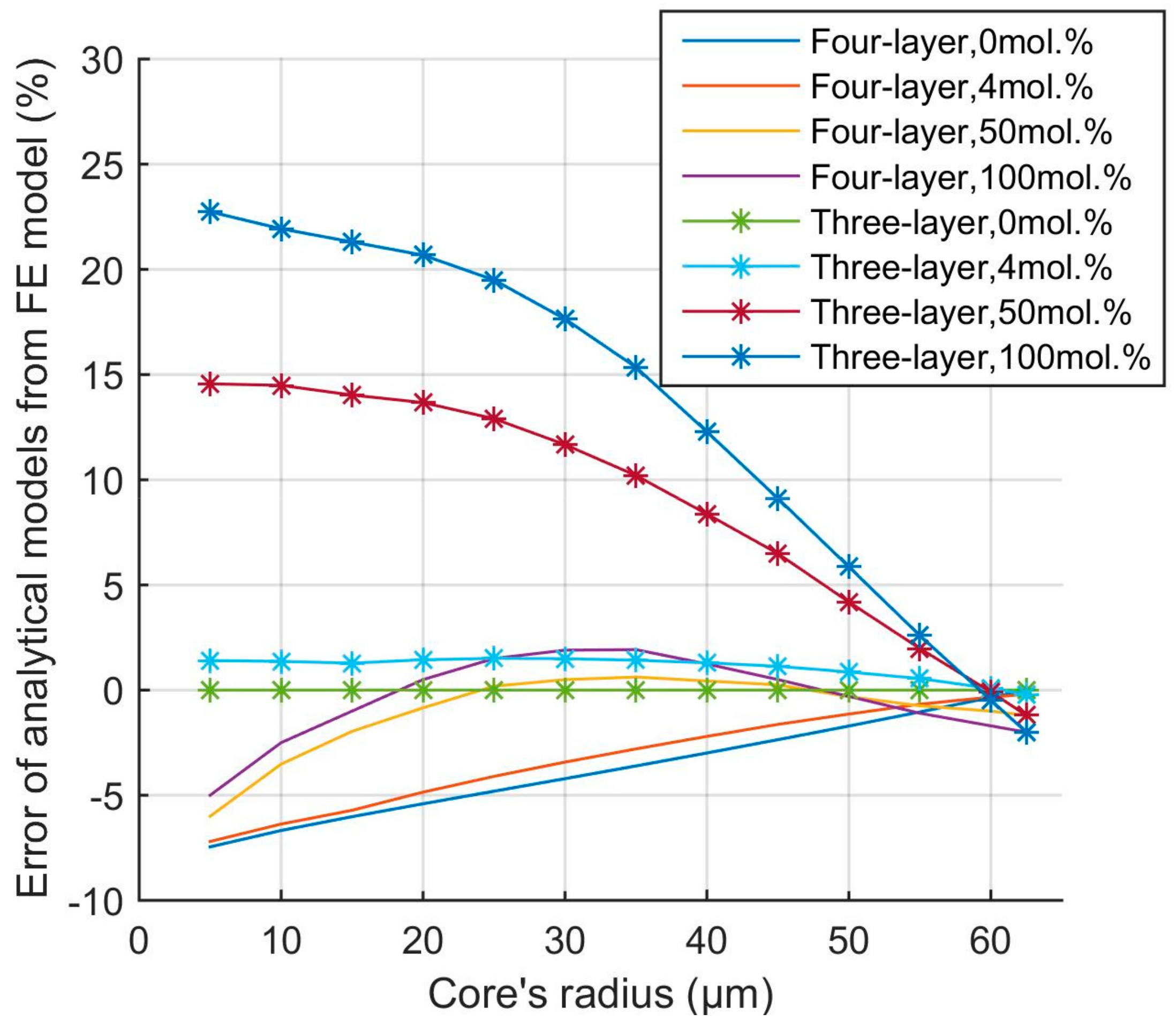
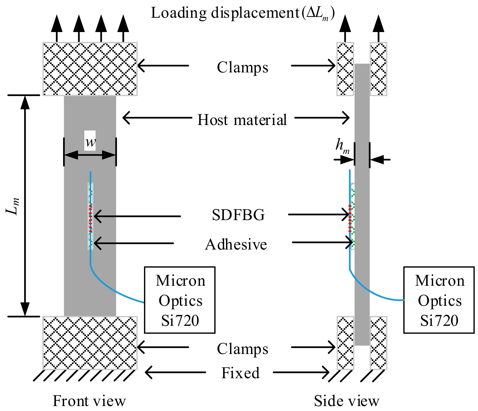
4. Experiment and Discussion

As listed in Table 3, three different kinds of SDFBGs with the same cladding radius were used in uniaxial tensile tests. Among them, SDBG-1 had the highest alumina content and largest core radius. Compared to SDFBG-1, SDFBG-2 had similar alumina content but a smaller core radius, while SDFBG-3 had lower alumina content but a similar core radius. These gratings were all fabricated with a 1550 nm central wavelength and 10 mm length by a near-infrared femtosecond laser in accordance with the point-by-point method.
Strain measured by the SDFBG sensor is expressed as
ε = Δ λ K ,
where Δ λ is the resonant-wavelength shift of the SDFBG induced by axial strain, and K is the axial-strain sensitivity, which is defined by [32]
K = 1 λ 0 1 1 2 n p 12 c o r e ν c o r e p 11 c o r e + p 12 c o r e ,
where λ 0 is the selected resonant wavelength. Refractive index n , two photoelastic constants p 12 c o r e and p 11 c o r e and Poisson ratio ν c o r e of the core were all determined by alumina content m and could be calculated by using the additive model [30] via each component’s bulk parameter in Table 4:
n = m n A l 2 O 3 + ( 1 m ) n S i O 2 p 11 c o r e = m p 11 A l 2 O 3 + ( 1 m ) p 11 S i O 2 p 12 c o r e = m p 12 A l 2 O 3 + ( 1 m ) p 12 S i O 2 ν c o r e = m ν A l 2 O 3 + ( 1 m ) ν S i O 2
The SDFBG was mounted onto a GH3536 specimen in load control to calibrate strain sensitivity using a universal testing machine C40 (MTS Systems, Co., Minnesota, USA). The schematic diagram and experiment setup are shown in Figure 8 and Figure 9, respectively. The adhesive was fabricated with half-bond length of 5 mm and bottom thickness of 0.1 mm. Static-displacement load was applied to the upper end of the specimen, while the nether end was fixed. Loaded strain was defined as ε = Δ L m / L m , where L m is the length of the specimen between two clamps at the initial stage, and Δ L m is the elongation of the specimen under static tensile loading. The reflection spectrum of the SDFBG was adopted by an optical sensing analyzer Si720 (Micron Optics, Inc., Atlanta, USA) with a spectral resolution of 0.25 pm.
The strain experiment was carried out at room temperature (about 20 °C) from 0 to 1000 με, with a step of 100 με. Theoretical and experiment results are listed in Table 5. Experimental ASTRs were obtained by dividing theoretical sensitivities by the corresponding experimental sensitivities. Compared to SDFBG-2, SDFBG-1 had a 20.3 μm larger core radius, but 5.4% lower experimental ASTR. Meanwhile, compared to SDFBG-3, SDFBG-1 had a 45.1 mol % higher alumina content, but a 3.6% lower experimental ASTR. As expected, the larger core diameter and higher alumina content led to lower ASTRs. Errors in the absolute value of the FE, and four- and three-layer models were calculated from the experiment results, as shown in Table 5. Results of the FE model were generally consistent for all gratings, and the highest error percentage was only 1.1%, mainly due to measurement uncertainty of the model parameters, such as adhesive size, alumina content, and core radius. Low error percentages (0.9% and 0.8%) for the four-layer model were obtained when the ASTRs of SDFBG-1 and -2 were predicted, while a high error percentage (5.2%) was obtained when the ASTR of SDFBG-3 was predicted. In contrast, high error percentages (9.2% and 14.7%) for the three-layer model were obtained when the ASTRs of SDFBG-1 and -2 were predicted, while a low error percentage (0.3%) was obtained when the ASTR of SDFBG-3 was predicted. Considering that SDFBG-1 and -2 had higher alumina content than that of SDFBG-3, the four- and three-layer models were proved to be suitable for calculating the ASTRs of SDFBGs with a high and low alumina content, respectively.

5. Conclusions

In this paper, an improved surface-bonded SDFBG strain-transfer model was theoretically proposed and experimentally demonstrated. The SDFBG with a high alumina content was considered an inhomogeneous material in the fiber region, and the measurement structure was abstracted into core, cladding, adhesive, and host material. The transfer function of the analytical model was derived according to shear-lag theory. Strain-transfer characteristics were analyzed using the four- and three-layer, and FE models. The core’s radius and the higher alumina content were found to have a significant effect on the ASTR. Simulation results indicated that the larger core’s radius and the higher content resulted in a lower transfer rate. For example, the ASTR calculated from the four-layer model decreased by about 20% when the alumina content was fixed at 50 mol %, and the core’s radius increased from 5 to 62.5 μm, while the ASTR decreased by about 8% when the core’s radius was fixed at 30 μm, and the alumina content increased from 0 to 100 mol %. The accuracy of the proposed model was verified by the strain experiment on a universal testing machine. The ASTR decreased by about 5% when the core’s radius increased from 10.5 to 30.8 μm, or alumina content increased from 4.5 to 49.6 mol %. The four- and three-layer models were found to be preferable for predicting the transfer rates of sensors with a high and low alumina content, respectively, and error percentages of less than 0.9% were obtained. This research can be used to instruct practical applications of and guarantee accurate measurements by SDFBG strain sensors.

Author Contributions

Conceptualization, P.Z. and Z.W.; methodology, P.Z.; validation, L.Z.; formal analysis, S.C.; investigation, Z.S.; writing—original-draft preparation, P.Z. All authors have read and agreed to the published version of the manuscript.

Funding

This research was funded by the National Natural Science Foundation of China, grant number 51575032.

Conflicts of Interest

The authors declare no conflict of interest.

References

  1. Zhang, X.; Peng, W.; Shao, L.; Pan, W.; Yan, L. Strain and temperature discrimination by using temperature-independent FPI and FBG. Sensor. Actuat. A Phys. 2018, 272, 134–138. [Google Scholar] [CrossRef]
  2. Liu, Y.; Wang, D. Fiber in-line Fabry-Perot interferometer with offset splicing for strain measurement with enhanced sensitivity. IEEE Photonic. J. 2018, 10, 1–8. [Google Scholar] [CrossRef]
  3. Tian, K.; Farrell, G.; Wang, X.; Yang, W.; Xin, Y.; Liang, H.; Lewis, E.; Wang, P. Strain sensor based on gourd-shaped single-mode-multimode-single-mode hybrid optical fibre structure. Opt. Express. 2017, 25, 18885–18896. [Google Scholar] [CrossRef] [PubMed] [Green Version]
  4. Liu, Y.; Lang, C.; Wei, X.; Qu, S. Strain force sensor with ultra-high sensitivity based on fiber inline Fabry-Perot micro-cavity plugged by cantilever taper. Opt. Express. 2017, 25, 7797–7806. [Google Scholar] [CrossRef]
  5. Liu, Y.; Qu, S.; Qu, W.; Que, R. A Fabry–Perot cuboid cavity across the fibre for high-sensitivity strain force sensing. J. Optics 2014, 16, 1054011–10540117. [Google Scholar]
  6. Leal-Junior, A.G.; Theodosiou, A.; Min, R.; Casas, J.; Diaz, C.R.; Dos Santos, W.M.; Pontes, M.J.; Siqueira, A.A.G.; Marques, C.; Kalli, K.; et al. Quasi-distributed torque and displacement sensing on a series elastic actuator’s spring using FBG arrays inscribed in CYTOP fibers. IEEE Sens. 2019, 19, 4054–4061. [Google Scholar] [CrossRef]
  7. Zhang, X.; Chen, J.; González-Vila, Á.; Liu, F.; Liu, Y.; Li, K.; Guo, T. Twist sensor based on surface plasmon resonance excitation using two spectral combs in one tilted fiber Bragg grating. J. Opt. Soc. Am. B 2019, 36, 1176. [Google Scholar] [CrossRef]
  8. Farhad, A.; Yuan, L. Mechanics of bond and interface shear transfer in optical fiber sensors. J. Eng. Mech. 1998, 124, 385–394. [Google Scholar]
  9. Li, J.; Zhou, Z.; Ou, J.P. Interface transferring mechanism and error modification of embedded FBG strain sensor. Smart Structures and Materials, San Diego, United States, 2004; Udd, E., Li, J., Inaudi, D., Zhou, Z., Ou, J.P., Eds.; SPIE: Bellingham, WA, USA, 2004. [Google Scholar]
  10. Wu, R.; Zheng, B.; Fu, K.; He, P.; Tan, Y. Study on strain transfer of embedded fiber Bragg grating sensors. Opt. Eng. 2014, 53, 0851051–0851056. [Google Scholar] [CrossRef]
  11. Liang, M.; Chen, N.; Fang, X.; Wu, G. Strain transferring mechanism analysis of the surface-bonded FBG sensor. Appl. Opt. 2018, 57, 5837–5843. [Google Scholar] [CrossRef]
  12. Her, S.; Huang, C. The effects of adhesive and bonding length on the strain transfer of optical fiber sensors. Appl. Sci. 2016, 6, 13. [Google Scholar] [CrossRef]
  13. Wan, K.T. Quantitative sensitivity analysis of surface attached optical fiber strain sensor. IEEE Sens. 2014, 14, 1805–1812. [Google Scholar] [CrossRef] [Green Version]
  14. Zhou, J.; Zhou, Z.; Zhang, D. Study on strain transfer characteristics of fiber Bragg grating sensors. J. Intel. Mat. Syst. Str. 2010, 21, 1117–1122. [Google Scholar] [CrossRef]
  15. Zhao, H.; Wang, Q.; Qiu, Y.; Chen, J.; Wang, Y.; Fan, Z. Strain transfer of surface-bonded fiber Bragg grating sensors for airship envelope structural health monitoring. J. Zhejiang Univ. Sci. A 2012, 13, 538–545. [Google Scholar] [CrossRef]
  16. Wang, H.; Xiang, P. Strain transfer analysis of optical fiber based sensors embedded in an asphalt pavement structure. Meas. Sci. Technol. 2016, 27, 075106. [Google Scholar] [CrossRef]
  17. Li, D.; Li, H.; Ren, L.; Song, G. Strain transferring analysis of fiber Bragg grating sensors. Opt. Eng. 2006, 45, 024402. [Google Scholar] [CrossRef]
  18. Wang, H.; Jiang, L.; Xiang, P. Improving the durability of the optical fiber sensor based on strain transfer analysis. Opt. Fiber. Technol. 2018, 42, 97–104. [Google Scholar] [CrossRef]
  19. Li, H.; Zhu, L.; Dong, M.; Lou, X.; Guo, Y. Analysis on strain transfer of surface-bonding FBG on Al 7075-T6 alloy host. Optik 2016, 127, 1233–1236. [Google Scholar] [CrossRef]
  20. Wang, Z.; Li, H.; Zhang, L.; Xue, J. Strain transfer characteristic of a fiber Bragg grating sensor bonded to the surface of carbon fiber reinforced polymer laminates. Appl. Sci. 2018, 8, 1171. [Google Scholar] [CrossRef] [Green Version]
  21. Shen, W.; Wang, X.; Xu, L.; Zhao, Y. Strain transferring mechanism analysis of the substrate-bonded FBG sensor. Optik 2018, 154, 441–452. [Google Scholar] [CrossRef]
  22. Wan, K.T.; Leung, C.K.Y.; Olson, N.G. Investigation of the strain transfer for surface-attached optical fiber strain sensors. Smart. Mater. and Struct. 2008, 17, 035037. [Google Scholar] [CrossRef]
  23. Wang, H.P.; Xiang, P.; Li, X. Theoretical analysis on strain transfer error of FBG sensors attached on steel structures subjected to fatigue load. Strain 2016, 52, 522–530. [Google Scholar] [CrossRef]
  24. Her, S.C.; Huang, C.Y. Effect of coating on the strain transfer of optical fiber sensors. Sensors (Basel) 2011, 11, 6926–6941. [Google Scholar] [CrossRef] [PubMed] [Green Version]
  25. Dragic, P.D.; Hawkins, T.; Foy, P.; Morris, S.; Ballato, J. Sapphire-derived all-glass optical fibres. Nat. Photonics 2012, 6, 627–633. [Google Scholar] [CrossRef]
  26. Zhang, P.; Zhang, L.; Wang, Z.; Zhang, X.; Shang, Z. Sapphire derived fiber based Fabry-Perot interferometer with an etched micro air cavity for strain measurement at high temperatures. Opt. Express 2019, 27, 27112–27123. [Google Scholar] [CrossRef]
  27. Liu, H.; Pang, F.; Hong, L.; Ma, Z.; Huang, L.; Wang, Z.; Wen, J.; Chen, Z.; Wang, T. Crystallization-induced refractive index modulation on sapphire-derived fiber for ultrahigh temperature sensing. Opt. Express 2019, 27, 6201. [Google Scholar] [CrossRef]
  28. Zhang, P.; Zhang, L.; Mourelatos, Z.P.; Wang, Z. Crystallization-sapphire-derived-fiber-based Fabry-Perot interferometer for refractive index and high-temperature measurement. Appl. Opt. 2018, 57, 9016–9021. [Google Scholar] [CrossRef]
  29. Elsmann, T.; Lorenz, A.; Yazd, N.S.; Habisreuther, T.; Dellith, J.; Schwuchow, A.; Bierlich, J.; Schuster, K.; Rothhardt, M.; Kido, L.; et al. High temperature sensing with fiber Bragg gratings in sapphire-derived all-glass optical fibers. Opt. Express 2014, 22, 26825–26833. [Google Scholar] [CrossRef]
  30. Dragic, P.; Ballato, J.; Ballato, A.; Morris, S.; Hawkins, T.; Law, P.C.; Ghosh, S.; Paul, M.C. Mass density and the Brillouin spectroscopy of aluminosilicate optical fibers. Opt. Mater. Express 2012, 2, 1641–1654. [Google Scholar] [CrossRef]
  31. Wang, Q.; Qiu, Y.; Zhao, H.; Chen, J.; Wang, Y.; Fan, Z. Analysis of strain transfer of six-layer surface-bonded fiber Bragg gratings. Appl. Opt. 2012, 51, 4129–4138. [Google Scholar] [CrossRef]
  32. Sirkis, J.S. Unified approach to phase-strain-temperature models for smart structure interferometric optical fiber sensors: Part 1, development. Opt. Eng. 1993, 32, 752. [Google Scholar] [CrossRef]
Figure 1. Four-layer model of surface-bonded sapphire-derived fiber Bragg grating (SDFBG) test system.
Applsci 10 04399 g001
Figure 2. Three-layer model regressed from four-layer model.
Applsci 10 04399 g002
Figure 3. Stress state in four-layer model.
Applsci 10 04399 g003
Figure 4. Influence of half-bond length and adhesive-bottom thickness on average strain-transfer rate (ASTR) calculated from three-layer model.
Applsci 10 04399 g004
Figure 5. Finite-element (FE) mesh of strain transfer.
Applsci 10 04399 g005
Figure 6. Influence of core radius and alumina content on average strain-transfer rate (ASTR) calculated from four-layer model and finite-element (FE) model.
Applsci 10 04399 g006
Figure 7. Errors of four- and three-layer models from finite-element (FE) model.
Applsci 10 04399 g007
Figure 8. Schematic diagram for strain calibration.
Applsci 10 04399 g008
Figure 9. Experiment setup for strain calibration.
Applsci 10 04399 g009
Table 1. Physical characteristics of materials used in strain-transfer model.
SapphireSilicaAdhesiveHost Material
E(GPa)5037210195
μ0.250.170.340.24
Table 2. Size of each layer in strain-transfer model.
rcorclhmwm
Size (mm)0.06250.06251.54.4
Table 3. Basic parameters of sapphire-derived fiber Bragg gratings (SDFBGs).
Alumina Content (mol %)Core Radius (μm)Cladding Radius (μm)
SDFBG-149.630.862.5
SDFBG-249.310.562.5
SDFBG-34.530.262.5
Table 4. Bulk parameters of alumina and silica.
Materialnνp11p12
Al2O31.6670.25−0.237−0.027
SiO21.4440.160.0980.226
Table 5. Theoretical and experiment results for strain-transfer rates.
Theoretical Sensitivity (pm/με)Experiment Sensitivity (pm/με)Experiment ASTR (%)FE ModelFour-Layer ModelThree-Layer Model
ASTR (%)Error 1 (%)ASTR (%)Error 1 (%)ASTR (%)Error 1(%)
SDFBG-11.371.1986.987.40.587.80.977.79.2
SDFBG-21.371.2692.392.10.293.10.877.614.7
SDFBG-31.291.1690.591.61.195.75.290.20.3
1 Error values calculated in absolute values.

