Article

A Textile-Based Microfluidic Platform for the Detection of Cytostatic Drug Concentration in Sweat Samples

by
Goran M. Stojanović
1,*,
Maja M. Radetić
2,
Zoran V. Šaponjić
3,
Marija B. Radoičić
3,
Milan R. Radovanović
1,
Željko V. Popović
1 and
Saša N. Vukmirović
4
1
Faculty of Technical Sciences, University of Novi Sad, Trg Dositeja Obradovića 6, 21000 Novi Sad, Serbia
2
Faculty of Technology and Metallurgy, University of Belgrade, Karnegijeva 4, 11120 Belgrade, Serbia
3
“Vinča” Institute of Nuclear Sciences, University of Belgrade, National Institute of the Republic of Serbia, P.O. Box 522, 11001 Belgrade, Serbia
4
Faculty of Medicine, University of Novi Sad, Hajduk Veljkova 3, 21000 Novi Sad, Serbia
*
Author to whom correspondence should be addressed.
Appl. Sci. 2020, 10(12), 4392; https://doi.org/10.3390/app10124392
Submission received: 20 May 2020 / Revised: 9 June 2020 / Accepted: 15 June 2020 / Published: 26 June 2020
(This article belongs to the Section Electrical, Electronics and Communications Engineering)

Abstract

:

Featured Application

Biomedical sector, sports sector—applications in the detection of drug concentrations in sweat samples.

Abstract

This work presents a new multilayered microfluidic platform, manufactured using a rapid and cost-effective xurography technique, for the detection of drug concentrations in sweat. Textile fabrics made of cotton and polyester were used as a component of the platform, and they were positioned in the middle of the microfluidic device. In order to obtain a highly conductive textile, the fabrics were in situ coated with different amounts of polyaniline and titanium dioxide nanocomposite. This portable microfluidic platform comprises at least three layers of optically transparent and flexible PVC foils which were stacked one on top of the other. Electrical contacts were provided from the edge of the textile material when a microfluidic variable resistor was actually created. The platform was tested in plain artificial sweat and in artificial sweat with a dissolved cytostatic test drug, cyclophosphamide, of different concentrations. The proposed microfluidic device decreased in resistance when the sweat was applied. In addition, it could successfully detect different concentrations of cytostatic medication in the sweat, which could make it a very useful tool for simple, reliable, and fast diagnostics.

1. Introduction

The fast-growing interest in sophisticated biomedical devices and wide-spreading Internet of Things paradigm has enabled the development of the “housepital” instead of “hospital” concept. That means that biomedical sensors and electronic devices can be used at home for the analysis of various physiological parameters of our bodies, and the results can be remotely sent to experts or caregivers for their opinion or decisions. To fully capitalize on the advantages and benefits of this concept, it is necessary to create chips which should be noninvasive, cost-effective, and simple for application, i.e., they should not require professional staff. Moreover, such devices should be based on flexible textiles incorporated into wearable electronic systems.
Among the wide range of textile fibers, cotton (CO) fibers are natural, sustainable, and widely applied in different spheres of everyday life, from clothes to technical textiles [1]. A highly conductive composite comprising polystyrene sulfonate/multiwalled carbon nanotubes/CO fibers with deposited polyaniline (PANI) was used for real-time monitoring of the pH value of the skin [2]. Generally, PANI is a particularly attractive polymer as it can be easily synthesized by chemical oxidative polymerization of a relatively cheap monomer with high yield. The modification of CO fabrics with PANI aiming to provide electrically conductive clothing material with better durability was studied in [3] or to tune the electrical properties of textile materials by grafting PANI nanofibers in [4]. The electrical characteristics of CO fabrics coated with PANI and polypyrrole were also examined in [5], where resistance values of 350 and 512 Ω, respectively, were obtained. In situ polymerization of aniline on textile materials was utilized for the fabrication of conductive composite fabrics PANI/AgNO3/CO and PANI/CO which ensured specific electrical resistivity of 15 × 105 Ω/cm and 15 × 103 Ω/cm, respectively [6]. Furthermore, other textile fibers such as polyester (PET) [7,8], polyamide [9], polyacryl [10], and wool [11] were also coated with PANI in order to obtain better electrical properties. The surface and bulk conductivity of CO, wool, and PET fabrics coated with PANI were also investigated in [12]. Hoghoghifard et al. studied the effect of different aniline polymerization conditions on the coating of PET fabric with conductive PANI and, consequently, on surface resistivity [13].
In the healthcare system, blood, urine, saliva, tears, and sweat are body fluids commonly used for the analysis of electrophysiological parameters. Among these samples, sweat is the most comfortable for subjects to be taken and the procedure is completely noninvasive. In addition, it can provide plenty of useful biochemical information in health diagnostics and sports performance. Colorimetric analysis of lactate, Na+, and K+ ion concentrations from sweat was reported in [14]. A skin-mounted device for monitoring the glucose level in sweat was presented in [15], and the device was fabricated via costly technological processes of lithography and screen-printing. Na+ and K+ ion concentrations in sweat were analyzed in [16] using ion-selective electrodes and also enabling the wireless transfer of measured data. The lactate level in sweat can be monitored using a biochemical analytical device developed in [17]. It was intended to be used for the monitoring of athletes’ performance during physical activity. A polydimethylsiloxane (PDMS)-based thin and soft epidermal system for collecting sweat from the pores on the skin and for measuring total sweat loss and pH was reported in [18]. It was experimentally tested on humans in indoor and outdoor environments. In [19], the authors presented a silicon-based chip, creating a “lab-on-a-skin” platform that enables the measurement of the K+ ion concentration in the sweat in real time (interval of 20 min demonstrated in the article). An elastomeric styrenic block copolymer was used in the paper [20] to create a stretchable microfluidic and electronic system which can be applied on the skin and can collect and measure sweat chloride levels in humans in an aquatic medium. A patch-like sensor was proposed in [21] for measuring the sweat secretion rate and total ionic charge concentration using an interdigitated electrode structure embedded in a microfluidic channel. In reference [22], the authors presented platforms composed of a triple-electrode array patterned on a PET substrate and connected with an electronic circuit on the printed circuit board for sensing caffeine from sweat. In paper [23], a CO thread was used to guide the sweat sample to the paper-based sensor, and with the assistance of a smartphone, the glucose concentration was monitored by observation of colorimetric changes. Nowadays, many people worldwide suffer from some type of cancer. One of the symptoms is night sweats [24]. Treatment with cytostatic drugs is still a part of standard protocol in the vast majority of hospitals. Keeping this in mind, it is important to investigate the concentration of cytostatics in sweat as a noninvasive procedure for subjects. This is significant not only for the estimation of drug treatment efficacy, but also for the explanation of some skin-related side effects, such as Grover’s disease, which appears as a consequence of the concentration of chemotherapy drug metabolites in sweat [25,26]. However, the above-mentioned solutions demand complex and costly technological processes for manufacturing of the whole device, and the systems are not based on textile materials.
In this study, a textile-based microfluidic platform fabricated using a xurogaphic technique for fast determination of the cytostatic drug concentration in artificial sweat is discussed. The core of the multilayered microfluidic structure is CO or PET fabric coated with PANI/TiO2 nanocomposites. In situ polymerization of PANI/TiO2 nanocomposites imparted different conductivity/resistivity values to the textile substrates. The microfluidic platform provides a fast tool for sweat manipulation, and the conductivity of the textile composite is changed with various sweat samples soaking the textile material. The performance of the platform was tested through monitoring different concentrations of the cytostatic drug cyclophosphamide in artificial sweat. The examination was realized by measuring the variation of electrical resistance at two terminals of the created microfluidic device in order to provide a proof of concept.

2. Materials and Methods

2.1. Preparation of the Fabrics

Desized and bleached cotton fabric (CO, 117.5 g/m2) and polyester fabric (PET, 115 g/m2) were washed in a bath (liquor-to-fabric ratio of 50:1) containing 0.05% nonionic washing agent Felosan RG-N (Bezema, Montlingen, Switzerland) for 15 min at 50 °C. After a single rinse with warm water (50 °C) for 3 min, thorough rinsing in tap water, and final rinsing with distilled water, the samples were dried at room temperature.

2.2. Synthesis of Colloidal TiO2 Nanoparticles

A 0.2 M colloid of TiO2 nanoparticles (NPs) (d ~ 5 nm) was synthesized by acidic hydrolysis of TiCl4. A volume of 6 mL of TiCl4 solution cooled down to −20 °C was added dropwise to 200 mL of cooled water (at 4 °C) under vigorous stirring and then kept at this temperature for 30 min. The pH of the solution was between 0 and 1, depending on the TiCl4 concentration. Slow growth of the particles was achieved by applying dialysis against water at 4 °C. The water was changed daily and the dialysis stopped when pH 3 was reached. A Spectra/Por dialysis membrane (molecular weight cutoff (MWCO) 3500; Spectrum Laboratories, Inc., Rancho Dominguez, CA, USA) was used for the dialysis of the colloidal dispersion. The concentration of the TiO2 colloid was determined spectrophotometrically from the peroxide complex (λ = 410 nm, ε410 = 710 M−1cm−1) based on the concentration of Ti4+ ions. The peroxide complex was formed after adding 2 mL of 30 wt.% H2O2 into a solution containing 20.9 mL of water, 2 mL of 96 wt.% H2SO4, and 0.1 mL of TiO2 colloid [27].

2.3. Synthesis of PANI/TiO2 on CO and PET Fabrics

PANI-coated CO and PET fabrics were fabricated by in situ polymerization of aniline (ANI) in the presence of colloidal TiO2 NPs with ammonium persulfate (APS) in acidic medium at room temperature. A volume of 3.7 mL of 0.2 M TiO2 colloid was added to a 1.2 M solution of HCl in a 50 mL volumetric flask. A quantity of 0.50 g of CO or PET fabric was immersed in this solution, and it was stirred for 10 min. Afterwards, both APS and ANI were added to the reaction mixture. The dispersion of ANI was prepared by adding 0.73 mL of ANI to 25 mL of 1.2 M solution of HCl. The APS solution was made by dissolving 2.282 g of APS in 25 mL of 1.2 M solution of HCl. The polymerization process lasted 60 min. Subsequently, the samples were rinsed in HCl solution (pH 3). In order to prepare CO and PET samples with larger amounts of PANI/TiO2 nanocomposites, the complete in situ polymerization of ANI in the presence of colloidal TiO2 NPs with APS in acidic medium was repeated one more time.

2.4. Preparation of the Sweat Samples

The developed microfluidic platform was tested in the following fluids: (a) a standard solution of artificial sweat, and (b) corresponding solutions of the cytostatic drug cyclophosphamide—CPA (Endoxan, BAXTER ONCOLOGY GMBH, Halle, Germany, 500 mg). Each 100 mL of artificial sweat contained 1.08 g of NaCl, 0.12 g of lactic acid, 0.13 g of urea, and aqua purificata sterilis. The pH value was adjusted to 6.5 with 1 M NaOH. CPA solutions were prepared by dissolving commercial CPA in the above-mentioned artificial sweat in order to obtain 2 w/v%, 4 w/v%, and 6 w/v% solutions. The concentrations of CPA were chosen according to data on the maximum CPA solubility in water (10–50 mg/mL (1–5%)) [28]. Fluids were stored at 4 °C in darkness up to the testing phase.

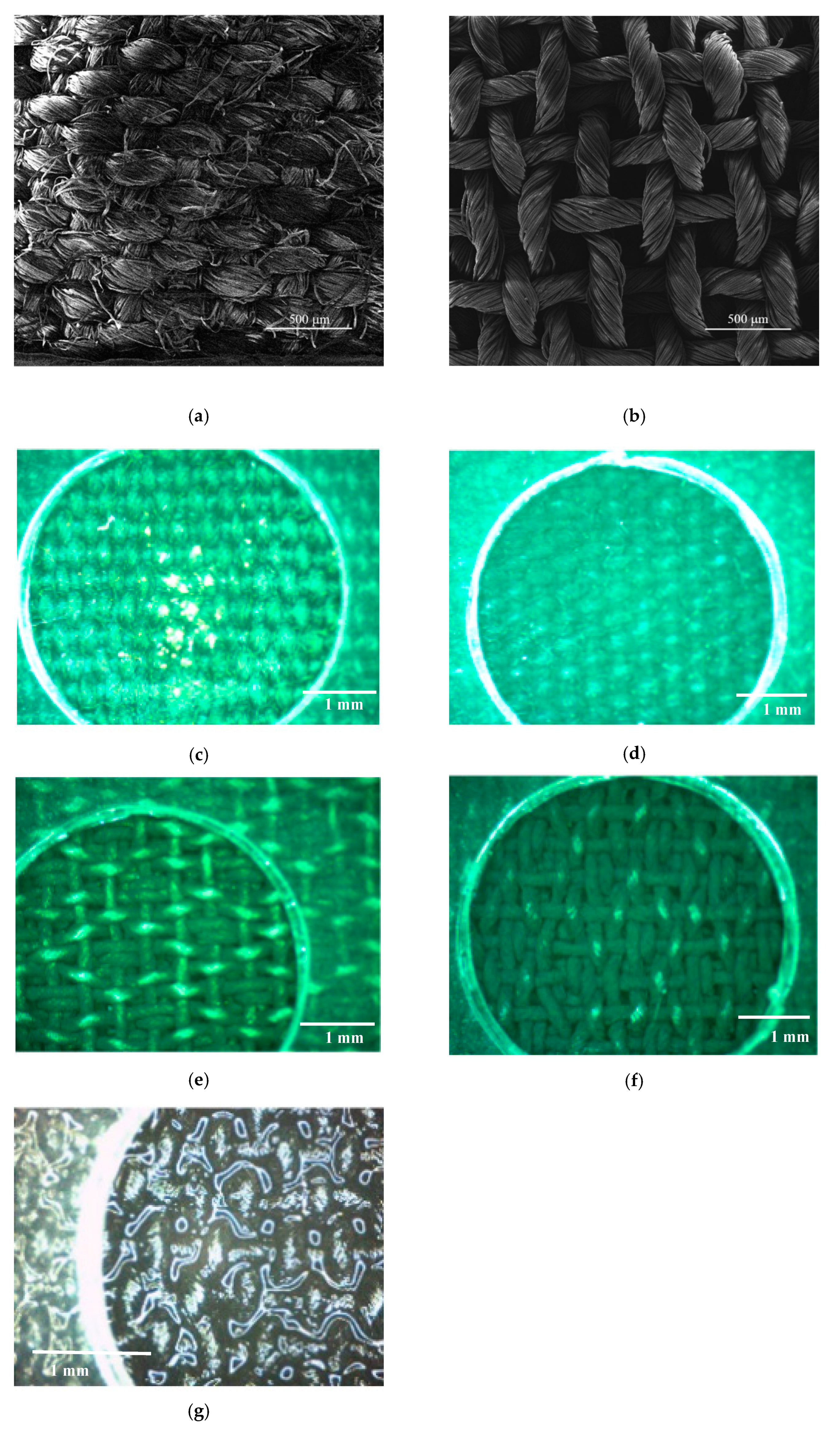
2.5. Design of the Microfluidic Platform

The microfluidic platform was manufactured using a rapid and cost-effective xurography method, which is based on the lamination of mechanically flexible polyvinyl chloride (PVC) foils and the creation of a multilayered structure. PVC foils can be cut (using a cutter plotter machine) in the desired shape or pattern and other materials can be incorporated between them, like a piece of textile material in our case. The design of separate layers of the microfluidic platform is shown in Figure 1a. The visual appearance of the complete microfluidic platform after the lamination process is presented in Figure 1b.
As can be seen in Figure 1a, the bottom layer of the structure is PVC foil. The middle layer is PVC foil with a carved microfluidic channel. Foils 80 μm thick were used. A piece of fabric with dimensions of 4 cm × 1 cm was positioned in the microfluidic channel. The number of PVC foils in the middle layer can be adjusted to the thickness of the textile substrate. Usually, we laminated two middle layers. Four combinations of textile materials were used to create different microfluidic chips, labelled as (a) CO-PANI/TiO2-1 (CO fabric impregnated with PANI/TiO2 nanocomposite once), (b) CO-PANI/TiO2-2 (CO fabric impregnated with PANI/TiO2 nanocomposite twice), (c) PET-PANI/TiO2-1 (PET fabric impregnated with PANI/TiO2 nanocomposite once), and (d) PET-PANI/TiO2-2 (PET fabric impregnated with PANI/TiO2 nanocomposite twice). The top layer is again PVC foil with three holes: (i) two square holes, with dimensions of 3 mm × 3 mm, for electrical terminals from the component (the distance between these two holes was around 3 cm) and (ii) one circular hole in the center of the structure, with a diameter of 4 mm (which corresponds to the diameter of the standard syringe, without needle), as an inlet for test fluids. The above-mentioned separate layers were laminated together at 130 °C in order to obtain a compact microfluidic platform, which is depicted in Figure 1b. The total dimensions of the microfluidic platform were 8 cm × 4 cm.

2.6. Characterization Methods

The morphology of the control fibers and fibers impregnated with PANI/TiO2 nanocomposite was assessed by field emission scanning electron microscopy (FESEM, Tescan Mira3 FEG, Brno, The Czech Republic). The samples were coated with a thin layer of Au prior to analysis. The Fourier transform infrared (FTIR) spectra of samples were recorded in the ATR mode using a Nicolet 6700 FTIR Spectrometer (Thermo Scientific, Waltham, MA, USA) at 2 cm−1 resolution, in the wavenumber range 500–4000 cm−1. The impedance spectroscopy method was applied for determination of the electrical parameters of the manufactured microfluidic platform. An HP4194A impedance analyzer instrument was used for measuring the electrical resistance on the electrical terminals utilizing two wires, shown in Figure 1a, in the frequency range from 100 Hz up to 40 MHz. The instrument was located in a Faraday cage and it was governed by a personal computer. The Labview software tool was used to set up measuring parameters and for the storage of measured data.

3. Results and Discussion

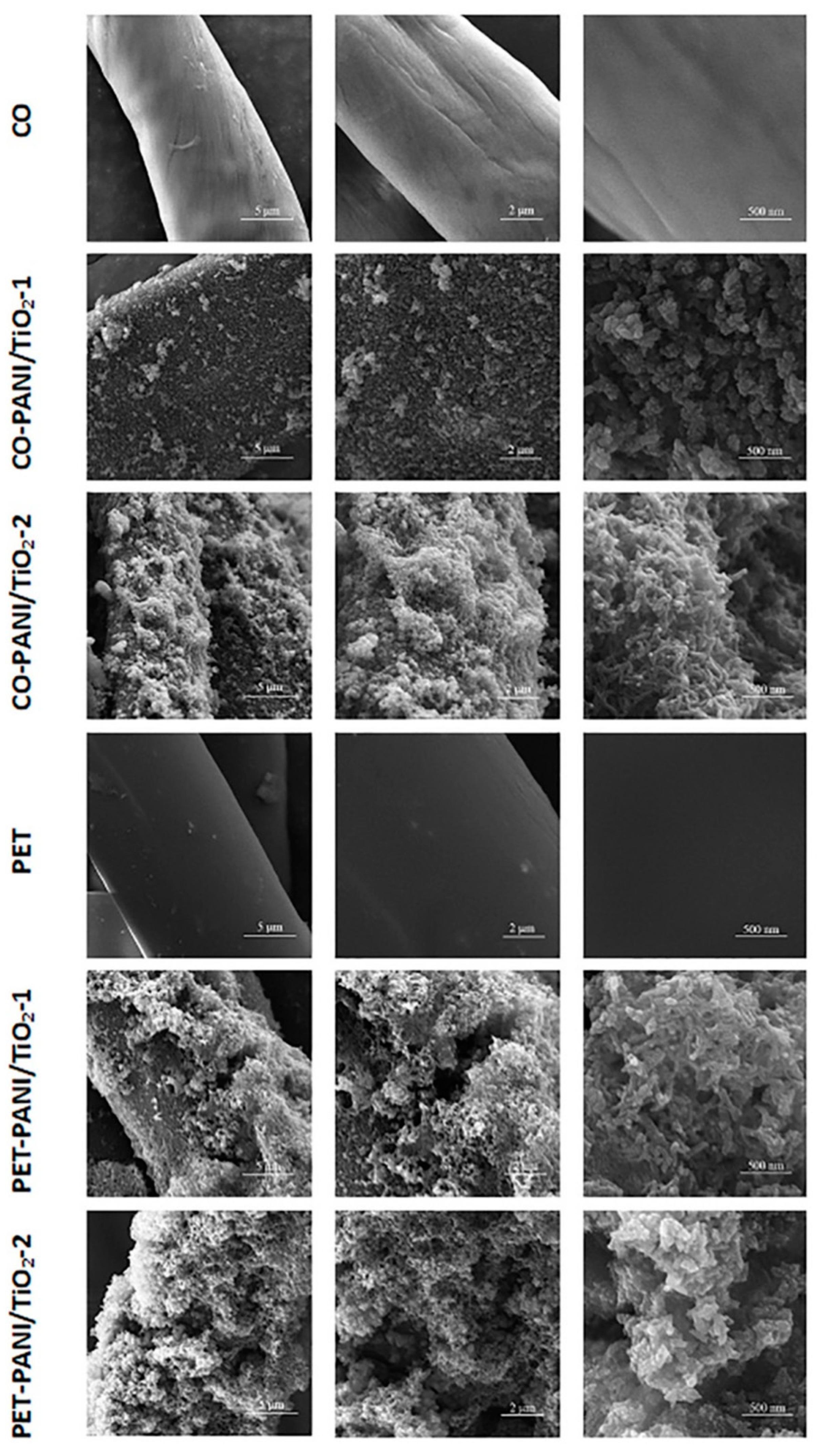
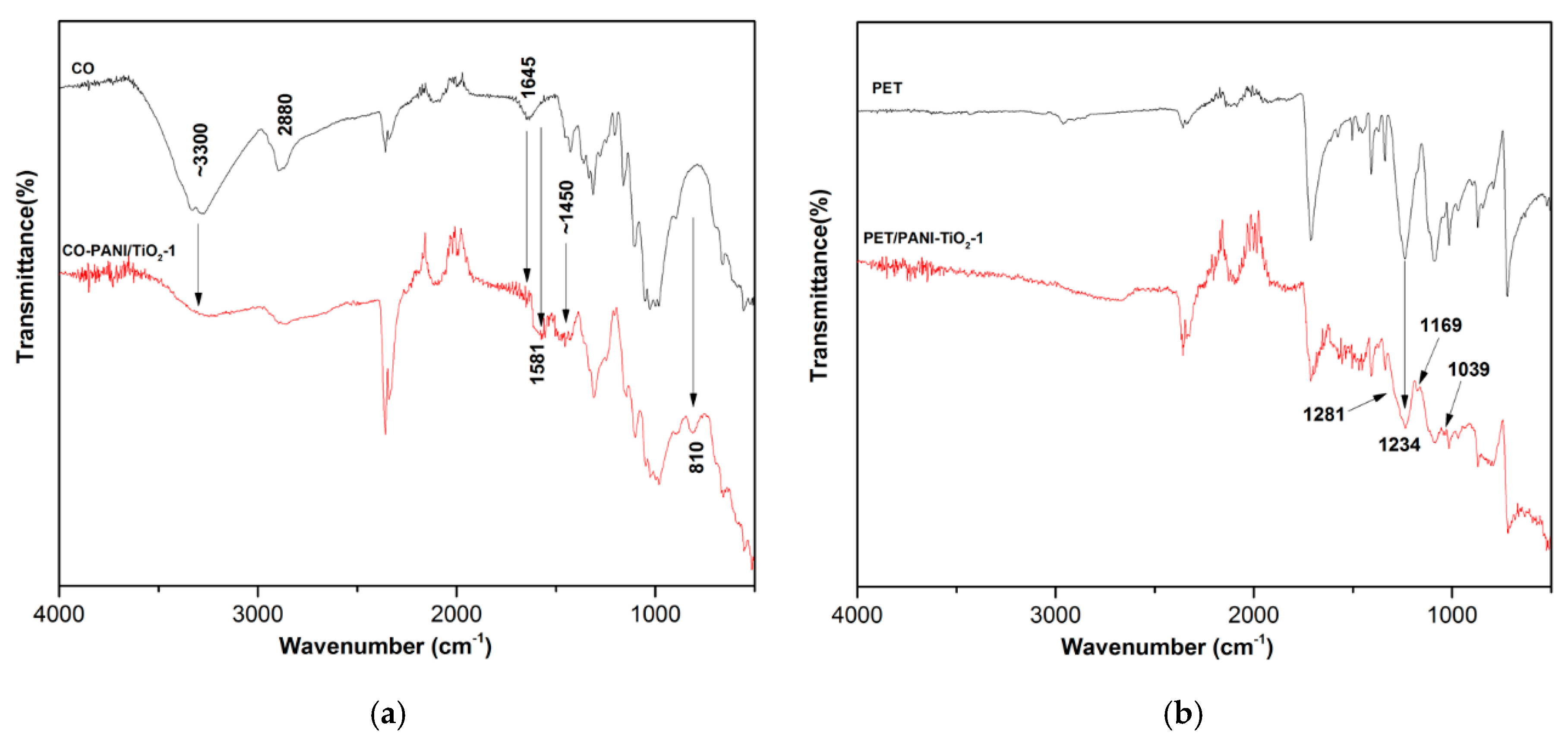
3.1. SEM and FTIR Analysis

The morphological changes to CO and PET fibers induced by impregnation with the PANI/TiO2 nanocomposite were assessed by FESEM analysis. SEM images of control CO and PET fibers and of the fibers impregnated with nanocomposite once or twice are presented in Figure 2. SEM images of each sample were intentionally taken under three different magnifications (×10,000, ×20,000, ×100,000) with an aim not only to confirm the presence of nanocomposite, but to estimate how much it covers the fiber surface and to gain insight into its morphological structure. Fibers are an integral part of the fabrics, and the coating efficiency of fibers either on the fabric surface or inside the yarns in inner parts of the fabrics should be uniform. In other words, the coating efficiency of fabrics is determined by the coating efficiency of the fibers. Imaging of fabrics under lower magnification cannot provide any information on the coating efficiency as it is impossible to distinguish since a very thin nanocomposite layer was formed. By proceeding with imaging under lower magnification it is possible only to get information on the construction of the fabrics. The SEM image of CO fiber reveals characteristic folds running parallel to the elongation direction of the pristine fiber. Single impregnation of CO fabric with PANI/TiO2 nanocomposite (CO-PANI/TiO2-1) resulted in the formation of a relatively uneven and thinner layer of nanocomposite. In other words, some segments were not fully covered with nanocomposite. It was noticed that the uniformity of CO-PANI/TiO2-1 fiber impregnation significantly varied from fiber to fiber, and it was the least uniform when compared to other samples. There was also an obvious difference between the fibers on the thread surface and those positioned inside the threads. Double impregnation (CO-PANI/TiO2-2) induced the formation of a much thicker layer of nanocomposite which actually covered the whole surface of the fibers. Rod-like nanostructures of PANI/TiO2 established a network on the PET fiber surface. The average diameter of the nanorods was approximately 50 nm. Such networked structures have been reported in literature, and they are a characteristic feature of PANI [29]. Eventually, the larger the amounts of generated nanocomposite, the larger the fiber diameter. As expected, the SEM images demonstrated the smooth surface of PET fibers. Our previous study implied that the morphology of the PET fiber surface impregnated with pure PANI significantly differs from that of PET fibers coated with PANI/TiO2 nanocomposite [30]. No signs of a PANI layer could be observed on the PET-PANI fibers, with only small patches of polymer randomly deposited over the fiber surface instead. The SEM images presented in Figure 2 clearly show that the presence of TiO2 NPs (mostly single crystalline, irregularly shaped NPs with average dimensions of 4.5 nm and anatase crystal structure [24]) strongly affected the polymerization of ANI, providing a completely different fiber surface morphology. The SEM image of PET-PANI/TiO2-1 fibers indicated that the amount of synthesized nanocomposite was considerably larger when compared to CO-PANI/TiO2-1 fibers modified under the same conditions. However, the thickness of nanocomposite varied even on a single fiber. The images taken under the highest magnification also revealed the appearance of a nanorod network on the PET fiber surface which highly resembles the morphology of the CO-PANI/TiO2-2 sample. It is clear that the PET-PANI/TiO2-2 fibers were entirely covered with huge amounts of polymer but the shape of the fibers was preserved. Like in the case of CO fibers, double impregnation led to the formation of larger amounts of nanocomposite when compared to single impregnation. However, instead of a nanorod networked structure, a very porous structure with differently shaped nanoplates appeared. In order to confirm the successful deposition of PANI/TiO2 nanocomposites on the surface of CO and PET fabrics, FTIR analysis was performed in ATR mode on both control and impregnated samples. The results of the FTIR analysis are shown in Figure 3. In comparison with the FTIR spectrum of control CO fabric, a survey FTIR spectrum of the CO-PANI/TiO2-1 sample (Figure 3a) revealed a significant decrease in intensity of a broad band at 3300 cm−1 assigned to stretching vibration of the cellulose OH group [31]. At the same time, the absorption band at 1645 cm−1 originating from HOH banding vibrations of adsorbed water disappeared [32,33,34,35]. In addition, a decrease in intensity of the band at 2880 cm−1 related to stretching vibration of the C-H group in the cellulose structure was observed. The detected changes in the FTIR spectrum of the CO-PANI/TiO2-1 sample associated with characteristic vibrations of CO could be an indicator of efficient deposition of the PANI/TiO2 nanocomposite layer. On the other hand, a new band appeared at 1580 cm−1 in the FTIR spectrum of the CO-PANI/TiO2-1 sample, which is assigned to stretching vibration of the quinonoid (Q) ring in the PANI emeraldine salt form. Stretching vibration of the Benzenoid (B) ring in the PANI emeraldine salt form and in-plane bending vibration of the C-H group of cellulose [31,36] contributed to the formation of a broad peak in the range between 1490 and 1420 cm−1. A peak positioned at 810 cm−1 corresponds to the out-of-plane deformation vibration of the aromatic C-H group in the 1,4-disubstituted benzene ring, γ(C-H), in linear N-C4 coupled PANI chains [37,38,39,40,41].
The results of FTIR analysis of the control PET and PET-PANI/TiO2-1 samples are presented in Figure 3b. The observed changes in the FTIR spectrum of the PET-PANI/TiO2 sample compared to the spectrum of the PET sample also indicated the successful deposition of PANI/TiO2 nanocomposite on the PET fiber surface. In particular, a new band appearing at ~1169 cm−1 in the FTIR spectrum of PET-PANI/TiO2-1 sample could be assigned to shifted stretching vibration of the –NH+= group in the B-NH+=Q segment in the bipolaron form of PANI emeraldine salt, while a low-intensity band positioned at 1039 cm−1 corresponds to vibrations of the hydrogen sulfate counter-ion [36,40]. Broadening of the strong peak at 1234 cm−1 associated with stretching vibration of the ester C=O group of PET in the FTIR spectrum of PET, i.e., the appearance of a shoulder in the long wavelength region (~1281 cm−1), is due to the contribution of stretching vibration of the C-N+• group in the polaron form of PANI emeraldine salt.

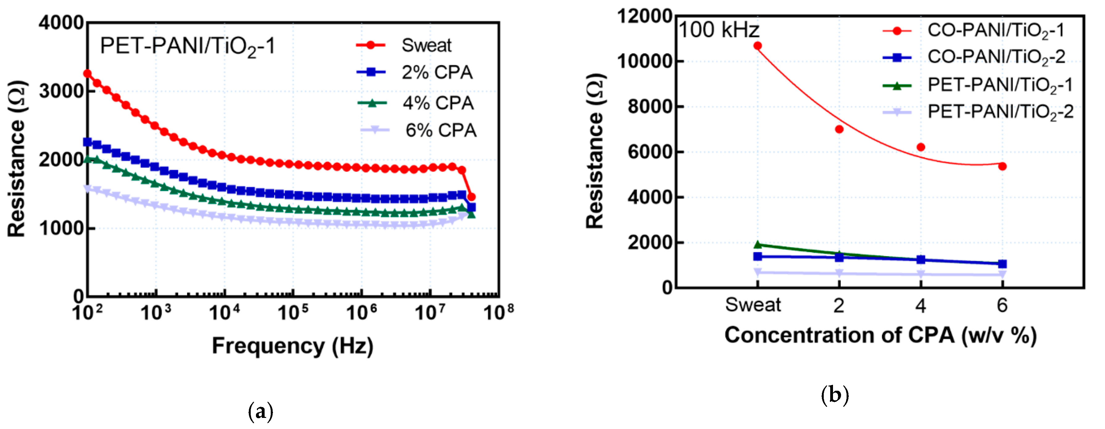
3.2. Electrical Parameter Testing and Drug Detection

Three microfluidic chips were fabricated using each of the four conductive textile samples, and they were tested in order to demonstrate a proof of the proposed concept. The instrumental errors were eliminated by a calibration procedure, as well as by setting a medium integration time and averaging four consecutive measurements. After the fabrication of the microfluidic chip, as shown in Figure 1b, measurements of electrical resistance between the two terminals when the dry fabrics were placed into the microfluidic channel were conducted. The measurements were repeated when the artificial sweat was injected by syringe into the channel, as illustrated in Figure 1a. Afterwards, the sweat solution with CPA medication was injected into the channel on all investigated textile materials. A magnified view through the central hole of the microfluidic structure on these four fabrics is presented in Figure 4, including the case when the sweat was injected into the fabric (Figure 4g).
These four different substrates in the middle of the microfluidic platform were exploited as a medium for delivering a small volume of artificial sweat and sweat with dissolved CPA (2 w/v%, 4 w/v%, and 6 w/v%). Thanks to the optical transparency of the PVC foils, it was possible to visually observe (from both sides) the process of fluid penetration into the internal structure of the studied fabrics. The fabrics in the middle of the microfluidic platform were very quickly completely soaked by the applied fluid, and the measurement of electrical characteristics was ready to begin. The electrical resistance as a function of frequency was measured for all studied fabrics and CPA concentrations. In all studied cases, the resistance of the dry structures was around 12 times higher than that of chips soaked with artificial sweat placed inside the microfluidic channel. Such behavior was expected because the ions in the artificial sweat solution enabled easier conduction between the two terminals and lower electrical resistance. Figure 5a shows the measurement results for the structure with PET-PANI/TiO2-1 fabric, which was already presented in Figure 4g. The shape of the curves in Figure 5a is completely consistent with the results for the real part of impedance from [42]. Three regions can be distinguished: (1) in the low frequency range, the polarization region; (2) in the middle frequency range, a region almost independent from frequency variation; and (3) at high frequencies, the dispersive region. This high frequency drop is related to the charging/discharging mechanism of the double-layer capacitance, which represents one of the elements in the equivalent circuit modelling. The measured resistances were relatively constant in the mid-frequency region (from 104 to 107 Hz). This could be due to the relaxation mechanism of the polymer chains [43] in the low frequency range (between 102 and 104 Hz) as well as the rearrangement of polaron and bipolaron structures of the PANI/TiO2 nanocomposite at higher frequencies (above 107 Hz). Bearing this in mind, we selected one frequency point (100 kHz) from these regions to present the obtained results for differently impregnated substrates. These results are depicted in Figure 5b, and they were used as calibration curves in the in-house-developed electronic system.
Structures with CO demonstrated higher values of electrical resistance in comparison with the analogous PET-based microfluidic chips. This is a result of larger amounts of deposited PANI/TiO2 nanocomposite on the PET fabrics, as could be seen in Figure 2. However, the influence of the fabric structure should not be neglected. CO fabric has denser structure when compared to PET fabric, which can be noticed in Figure 4a,b. In spite of the hydrophobicity of PANI, the more open construction of impregnated PET fabrics enabled better fluid adsorption into the textile, which was proved by a simple drop test. A drop of distilled water immediately wetted the surface of impregnated PET fabrics, while impregnated CO fabrics took some time to get wetted. Taking into account that most of the microfluidic applications of textiles are based on the wicking phenomenon, which is strongly affected by pore geometry, number of fibers in the yarn, yarn linear density, and weaving pattern [44], combined with the fact that wickability and wettability are tightly related, it is very likely that the less-dense structure of PET fabrics positively influenced the transport of fluid through the impregnated PET fabrics and hence contributed to better conductivity mechanisms. Coating of both CO and PET fabrics with smaller amounts of conductive PANI/TiO2 nanocomposite resulted in higher electrical resistance, whereas larger amounts of PANI/TiO2 as a coating contributed to increased conductivity and, consequently, lower electrical resistance. This is due to the increased number of polarons and bipolarons in the structure and, consequently, improved conductivity. PANI/TiO2 nanocomposite coating creates an efficient network for charge transport in the PANI matrix and, accordingly, a better conduction mechanism can be achieved. The decrease in resistance with an increase in the concentration of CPA was more prominent in the samples impregnated with smaller amounts of PANI/TiO2 nanocomposite (CO-PANI/TiO2-1 and PET-PANI/TiO2-1). The same trend was reported in reference [22]. The artificial sweat solution consisted of several ions: Na+, K+, Cl, and lactate ions. It is very likely that an increase of CPA concentration in artificial sweat solutions led to an increase of the concentration of Cl ions originating from CPA [45], contributing to better conductivity and consequently resulting in a decrease of electrical resistance on the terminals of the proposed component. However, their influence seems to be weaker in the case of samples that were impregnated with larger amounts of PANI/TiO2 nanocomposite. In order to quantitatively determine the sensing performance of the studied samples, two metrics were taken into account—sensitivity and linearity, which are both important for the applicability of the proposed platform. In our case, the sensitivity is defined as |S| = Δ RC, where Δ R is variation of resistance and Δ C is change in CPA concentration from 0 to 6 w/v%. As a measure of goodness of linear fit, R2 (coefficient of determination) was used. These two parameters are presented in Table 1 for the four analyzed textile-based structures.
It can be concluded from Table 1 that sample CO-PANI/TiO2-1 demonstrated the highest sensitivity but the lowest linearity. From a practical applications point of view, some kind of compromise should be achieved between these two performance indicators by tuning of the PANI/TiO2 nanocomposite amount on the fiber surface. For example, the sample PET-PANI/TiO2-1 demonstrated the highest linearity and acceptable sensitivity. By placing textile materials of different conductivity, we actually manufactured a variable resistor in the microfluidic world, and numerous fluids inside the component could additionally contribute to the alteration of the total electrical resistance on the two terminals. It is important to note that the fabricated microfluidic platform can be easily mounted onto wearables or applied directly to the skin. The complete electronic device was developed for processing and displaying measured data from the proposed microfluidic platform. A block diagram of the main steps is depicted in Figure 6a. The electronic read-out system was incorporated into a hand-held plastic package (Figure 6b) where it was possible to select the type of the fabric (as well as the frequency point) on the display, and the real-time measured concentration of CPA was presented on the display. The electronic device functions on the principle of an auto-range ohmmeter, meaning that the device constantly performs monitoring under the microfluidic sensing platform. The Arduino Nano system with an ATmega328P microcontroller represents the main part of the device. The system is capable of calculating the concentration of applied drug in real time on the basis of the measured resistance. The refreshment of the presented values on the Organic Light Emitting Diode (OLED) display is performed each 500 ms. The display has resolution of 128 × 64 pixels and the possibility to present data in a combination of blue and yellow colors. The electronic system is supplied with a voltage of 5 V.
It is also possible to collect sweat in vivo using the described microfluidic platform, and with the assistance of our portable electronic system or with a mobile phone, different parameters or biomarker concentration changes in sweat can be monitored.

4. Conclusions

In this paper, we proposed a novel microfluidic platform where the individual PVC layers were stacked under pressure between laminator rollers and at elevated temperature in order to produce a compact microfluidic variable resistor. The core of this microfluidic component is conductive flexible textile material, placed in the microfluidic channel, in the center of the structure. The proposed textile materials were CO or PET fabrics coated with PANI/TiO2 nanocomposite. The fabrics could soak up sweat as an easily accessible biofluid. The size of the piece of textile material and the whole microfluidic chip can be adjusted to the surface on the body where sweat will be collected. The amounts of in situ synthesized PANI/TiO2 nanocomposite strongly affected the electrical resistance of the chip. Larger amounts and higher uniformity of the nanocomposite layer led to an increase in electrical conductivity. The electrical resistance also changed depending on the fluids that were injected into the channel (incorporated into the internal structure of the studied textile materials). The higher the concentration of the cytostatic drug CPA, the lower the values of electrical resistance.
By tuning the amounts of synthesized PANI/TiO2 nanocomposite on the fiber surface, the sensing parameters of the chip, such as sensitivity or linearity, can be optimized, which is important for the practical application of this platform. Additionally, a complete hand-held electronic device was developed for processing and displaying the measured data from the proposed microfluidic platform.
Further research in this area will be oriented towards clinical trials with an aim to analyze CPA sweat concentrations on human subjects and to test the performance of our textile-based microfluidic platform (determination of the limit of detection (LOD) and limit of quantification (LOQ)), as well as to determine a possible correlation between blood and sweat CPA concentrations.

Author Contributions

Conceptualization, G.M.S., M.M.R. and Z.V.Š.; methodology, M.M.R. and Z.V.Š.; investigation, M.B.R., M.R.R., Ž.V.P. and S.N.V.; writing—original draft preparation, G.M.S.; writing—review and editing, M.M.R. and Z.V.Š.; visualization, Ž.V.P. All authors have read and agreed to the published version of the manuscript.

Funding

This study has received funding from the European Union’s Horizon 2020 research and innovation programme under grant agreement No. 854194.

Conflicts of Interest

The authors declare no conflict of interest.

References

  1. Zhang, Y.; Cui, Y. Cotton-based wearable PEDOT:PSS electronic sensor for detecting acetone vapour. Flex. Print. Electron. 2017, 2, 042001. [Google Scholar] [CrossRef]
  2. Smith, R.E.; Totti, S.; Velliou, E.; Campagnolo, P.; Hingley-Wilson, S.M.; Ward, N.I.; Varcoe, J.R.; Crean, C. Development of a novel highly conductive and flexible cotton yarn for wearable pH sensor technology. Sens. Actuators B Chem. 2019, 287, 338–345. [Google Scholar] [CrossRef]
  3. Bhat, N.V.; Seshadri, D.T.; Radhakrishnan, S. Preparation, Characterization, and Performance of Conductive Fabrics: Cotton + PANI. Text. Res. J. 2004, 74, 155–166. [Google Scholar] [CrossRef]
  4. Tissera, N.D.; Wijesena, R.N.; Rathnayake, S.; Silva, R.M.; Nalin, K.M. Heterogeneous in situ polymerization of Polyaniline (PANI) nanofibers on cotton textiles: Improved electrical conductivity, electrical switching, and tuning properties. Carbohydr. Polym. 2018, 186, 35–44. [Google Scholar] [CrossRef]
  5. Onar, N.; Aksit, A.C.; Ebeoglugil, M.F.; Birlik, I.; Celik, E.; Ozdemir, I. Structural, Electrical, and Electromagnetic Properties of Cotton Fabrics Coated with Polyaniline and Polypyrrole. J. Appl. Polym. Sci. 2009, 114, 2003–2010. [Google Scholar] [CrossRef]
  6. Altinok, A.S.; Ucgul, I.; Oksuz, A.U. Production of polyester/polyaniline, cotton/polyaniline composite fabrics and examining electrical characteristics. Tekst. Appar./Tekst. Ve Konfeksiyon 2014, 24, 21–25. [Google Scholar]
  7. Engin, F.A.; Usta, I. Electromagnetic shielding effectiveness of polyester fabrics with polyaniline deposition. Text. Res. J. 2014, 84, 903–912. [Google Scholar] [CrossRef]
  8. Youssefi, M.; Motamedi, F. An electrically conductive hybrid polyaniline/silver-coated polyester fabric for smart applications. J. Ind. Text. 2019, 4, 1–16. [Google Scholar] [CrossRef]
  9. Hong, K.H.; Oh, K.W.; Kang, T.J. Polyaniline–nylon 6 composite fabric for ammonia gas sensor. J. Appl. Polym. Sci. 2004, 92, 37–42. [Google Scholar] [CrossRef]
  10. Hirase, R.; Shikata, T.; Shirai, M. Selective formation of polyaniline on wool by chemical polymerization, using potassium iodate. Synth. Met. 2004, 146, 73–77. [Google Scholar] [CrossRef]
  11. Nouri, M.; Haghighatkish, H.; Entezami, A.A.; Edrisi, E. Conductivity of textile fibres treated with aniline. Iran. Polym. J. 2000, 9, 49–58. [Google Scholar]
  12. Teli, M.; Dash, S.; Desai, P. Polyaniline Based Conductive Textiles. J. Inst. Eng. India Ser. E 2014, 95, 75–79. [Google Scholar] [CrossRef]
  13. Hoghoghifard, S.; Mokhtari, H.; Dehghani, S. Improving the conductivity of polyaniline coated polyester textile by optimizing the synthesis conditions. J. Ind. Text. 2016, 46, 611–623. [Google Scholar] [CrossRef]
  14. Choi, J.; Kang, D.; Han, S.; Kim, S.B.; Rogers, J.A. Thin, Soft, Skin-Mounted Microfluidic Networks with Capillary Bursting Valves for Chrono-Sampling of Sweat. Adv. Healthc. Mater. 2017, 6, 1601355. [Google Scholar] [CrossRef] [PubMed]
  15. Martín, A.; Kim, J.; Kurniawan, J.F.; Sempionatto, J.R.; Moreto, J.R.; Tang, G.; Campbell, A.S.; Shin, A.; Lee, M.Y.; Liu, X.; et al. Epidermal Microfluidic Electrochemical Detection System: Enhanced Sweat Sampling and Metabolite Detection. ACS Sens. 2017, 2, 1860–1868. [Google Scholar] [CrossRef] [PubMed]
  16. Alizadeh, A.; Burns, A.; Lenigk, R.; Gettings, R.; Ashe, J.; Porter, A.; McCaul, M.; Barrett, R.; Diamond, D.; White, P.; et al. A wearable patch for continuous monitoring of sweat electrolytes during exertion. Lab A Chip 2018, 18, 2632–2641. [Google Scholar] [CrossRef]
  17. Baysal, G.; Kök, F.N.; Trabzon, L.; Kızıl, H.; Göcek, İ.; Kayaoğlu, B.K. Microfluidic Nonwoven-Based Device as a Potential Biosensor for Sweat Analysis. Appl. Mech. Mater. 2014, 490–491, 274–279. [Google Scholar] [CrossRef]
  18. Koh, A.; Kang, D.; Xue, Y.; Lee, S.; Pielak, R.M.; Kim, J.; Hwang, T.; Min, S.; Banks, A.; Bastien, P.; et al. A soft, wearable microfluidic device for the capture, storage, and colorimetric sensing of sweat. Sci. Transl. Med. 2016, 8, 366ra165. [Google Scholar] [CrossRef] [Green Version]
  19. Garcia-Cordero, E.; Bellando, F.; Zhang, J.; Wildhaber, F.; Longo, J.; Guérin, H.; Ionescu, A.M. Three-Dimensional Integrated Ultra-Low-Volume Passive Microfluidics with Ion-Sensitive Field-Effect Transistors for Multiparameter Wearable Sweat Analyzers. ACS Nano 2018, 12, 12646–12656. [Google Scholar] [CrossRef]
  20. Reeder, J.T.; Choi, J.; Xue, Y.; Gutruf, P.; Hanson, J.; Liu, M.; Ray, T.; Bandodkar, A.J.; Avila, R.; Xia, W.; et al. Waterproof, electronics-enabled, epidermal microfluidic devices for sweat collection, biomarker analysis, and thermography in aquatic settings. Sci. Adv. 2019, 5, eaau6356. [Google Scholar] [CrossRef] [Green Version]
  21. Yuan, Z.; Hou, L.; Bariya, M.; Nyein, H.Y.Y.; Tai, L.C.; Ji, W.; Li, L.; Javey, A. A Multi-Modal Sweat Sensing Patch for Cross-Verification of Sweat Rate, Total Ionic Charge, and Na+ Concentration. Lab A Chip 2019, 19, 3179–3189. [Google Scholar] [CrossRef] [PubMed]
  22. Tai, L.C.; Gao, W.; Chao, M.; Bariya, M.; Ngo, Q.P.; Shahpar, Z.; Nyein, H.Y.Y.; Park, H.; Sun, J.; Jung, Y.; et al. Methylxanthine Drug Monitoring with Wearable Sweat Sensors. Adv. Mater. 2018, 30, 1707442. [Google Scholar] [CrossRef] [PubMed]
  23. Xiao, G.; He, J.; Chen, X.; Qiao, Y.; Wang, F.; Xia, Q.; Yu, L.; Lu, Z. A wearable, cotton thread/paper-based microfluidic device coupled with smartphone for sweat glucose sensing. Cellulose 2019, 26, 4553–4562. [Google Scholar] [CrossRef]
  24. Van Agthoven, M.; Sonneveld, P.; Verdonck, L.F.; Uyl-De Groot, C.A. Cost determinants in aggressive non-Hodgkin's lymphoma. Haematologica 2005, 90, 661–671. [Google Scholar]
  25. Lescoat, A.; Droitcourt, C.; Stock, N.; le Gall, F.; Dupuy, A. Vemurafenib-Induced Eccrine Squamous Syringometaplasia. Dermatology 2013, 226, 362–364. [Google Scholar] [CrossRef]
  26. Gupta, M.; Huang, V.; Linette, G.; Cornelius, L. Unusual complication of vemurafenib treatment of metastatic melanoma: Exacerbation of acantholytic dyskeratosis complicated by Kaposi varicelliform eruption. Arch. Dermatol. 2012, 148, 966–968. [Google Scholar] [CrossRef]
  27. Radoičić, M. Nanocomposites Based on Polyaniline and Titan (IV) Oxide: Synthesis, Characterization and Application in Photocatalysis. Ph.D. Thesis, University of Belgrade, Beograd, Serbia, 2013. [Google Scholar]
  28. Budavari, S.; O’Neil, M.J.; Smith, A.; Heckelman, P.E. (Eds.) The Merck Index, 11th ed.; Merck: Rahway, NJ, USA, 1989. [Google Scholar]
  29. Radoičić, M.; Ćirić-Marjanović, G.; Šaponjić, Z.; Mitrić, M.; Konstantinović, Z.; Stoiljković, M.; Nedeljković, J. Structural and magnetic properties of nanocomposites based on nanostructured polyaniline and titania nanotubes. J. Mater. Sci. 2013, 48, 5776–5787. [Google Scholar] [CrossRef]
  30. Radoičić, M.; Milošević, M.; Miličević, D.; Suljovrujić, E.; Ćirić-Marjanović, G.; Radetić, M.; Šaponjić, Z. Influence of TiO2 nanoparticles on formation mechanism of PANI/TiO2 nanocomposite coating on PET fabric and its structural and electrical properties. Surf. Coat. Technol. 2015, 278, 38–47. [Google Scholar] [CrossRef]
  31. Milovanovic, S.; Stamenic, M.; Markovic, D.; Radetic, M.; Zizovic, I. Solubility of thymol in supercritical carbon dioxide and its impregnation on cotton gauze. J. Supercrit. Fluid. 2013, 84, 173–181. [Google Scholar] [CrossRef]
  32. Tomšič, B.; Simončič, B.; Orel, B.; Vilčnik, A.; Spreizer, H. Biodegradability of cellulose fabric modified by imidazolidinone. Carbohyd. Polym. 2007, 69, 478–488. [Google Scholar] [CrossRef]
  33. Hofstetter, K.; Hinterstoisser, B.; Salmén, L. Moisture uptake in native cellulose—the roles of different hydrogen bonds: A dynamic FT-IR study using Deuterium exchange. Cellulose 2006, 13, 131–145. [Google Scholar] [CrossRef]
  34. Kondo, T. The assignment of IR absorption bands due to the freehydroxyl groups in cellulose. Cellulose 1997, 4, 281–292. [Google Scholar] [CrossRef]
  35. Łojewska, J.; Miskowiec, P.; Łojewski, T.; Proniewicz, L.M. Cellulose oxidative and hydrolytic degradation: In situ FTIR approach. Polym. Degrad. Stabil. 2005, 88, 512–520. [Google Scholar] [CrossRef]
  36. Radoičić, M.; Šaponjić, Z.; Nedeljković, J.; Ćirić-Marjanović, G.; Stejskal, J. Self-assembled polyaniline nanotubes and nanoribbons/titanium dioxide nanocomposites. Synth. Met. 2010, 160, 1325–1334. [Google Scholar] [CrossRef]
  37. Trchova, M.; Konyushenko, E.N.; Stejskal, J.; Šedenkova, I.; Holler, P.; Ćirić-Marjanović, G. Evolution of polyaniline nanotubes: The oxidation of aniline in water. J. Phys. Chem. B 2006, 110, 9461–9468. [Google Scholar] [CrossRef]
  38. Stejskal, J.; Sapurina, I.; Trchova, M.; Konyushenko, E.N.; Holler, P. The genesis of polyaniline nanotubes. Polymer 2006, 47, 8253–8262. [Google Scholar] [CrossRef]
  39. Janošević, A.; Ćirić-Marjanović, G.; Marjanović, B.; Holler, P.; Trchova, M.; Stejskal, J. Synthesis and characterization of conducting polyaniline 5 sulfosalicylate nanotubes. Nanotechnology 2008, 19, 135606. [Google Scholar] [CrossRef] [PubMed]
  40. Kang, E.T.; Neoh, K.G.; Tan, K.L. Polyaniline: A polymer with many interesting intrinsic redox states. Prog. Polym. Sci. 1998, 23, 277–324. [Google Scholar] [CrossRef]
  41. Socrates, G. Infrared and Raman Characteristic Group Frequencies: Tables and Charts; Wiley: New York, NY, USA, 2001; pp. 65–84, 107–109, 157–165, 249–261. [Google Scholar]
  42. Liu, G.; Alomari, M.; Sahin, B.; Snelgrove, S.E.; Edwards, J.; Mellinger, A.; Kaya, T. Real-time sweat analysis via alternating current conductivity of artificial and human sweat. Appl. Phys. Lett. 2015, 106, 133702. [Google Scholar] [CrossRef]
  43. Kar, P.; Choudhury, A. Electrical and dielectric properties of polyaniline doped with carboxyl-functionalized multiwalled carbon nanotube. Adv. Polym. Technol. 2013, 32, E760–E770. [Google Scholar] [CrossRef]
  44. Naeimirad, M.; Abuzade, R.A.; Babaahmadi, V.; Dabirian, F. Microfluidic through fibrous structures: Recent developments and future trends. Mater. Des. Process. Commun. 2019, 1, e78. [Google Scholar] [CrossRef] [Green Version]
  45. Allwood, M.; Stanley, A.; Wright, P. (Eds.) The Cytotoxics Handbook; Radcliffe Publishing: London, UK, 2002; p. 294. [Google Scholar]
Figure 1. (a) Design of the separate layers; (b) the manufactured textile-based microfluidic platform.
Applsci 10 04392 g001
Figure 2. SEM images of control and impregnated CO and PET fibers.
Applsci 10 04392 g002
Figure 3. FTIR spectra of (a) CO and CO-PANI/TiO2-1 samples and (b) PET and PET-PANI/TiO2-1 samples.
Applsci 10 04392 g003
Figure 4. (a) SEM image of CO fabric, (b) SEM image of PET fabric, and magnified views of the microfluidic platforms with (c) CO-PANI/TiO2-1; (d) CO-PANI/TiO2-2; (e) PET-PANI/TiO2-1; (f) PET-PANI/TiO2-2; and (g) PET-PANI/TiO2-1 with injected artificial sweat.
Applsci 10 04392 g004
Figure 5. (a) Resistance as a function of frequency for PET-PANI/TiO2-1 and for different fluids soaking the fabric; (b) Resistance as a function of cyclophosphamide (CPA) concentration for different fabrics.
Applsci 10 04392 g005
Figure 6. (a) A block diagram of the electronic circuit for data acquisition from the microfluidic platform, processing and displaying measured data (ADC - analog-to-digital converter); (b) The electronic device for displaying the measured concentration of CPA.
Applsci 10 04392 g006
Table 1. Sensitivity and linearity of the analyzed structures.
Microfluidic Platform TypeSensitivity |S|
(Ω/w/v% of CPA)
R2
CO-PANI/TiO2-1888.330.8515
CO-PANI/TiO2-255.000.9199
PET-PANI/TiO2-1141.660.9539
PET-PANI/TiO2-217.000.9383

