Article

Energy Consumption Analysis of Beamforming and Cooperative Schemes for Aircraft Wireless Sensor Networks

Kumoh National Institute of Technology, ICT Convergence Research Center, 61 Daehak-ro, Gumi 39177, Gyeongsangbuk-do, Korea
*
Author to whom correspondence should be addressed.
Kim, S.-H.; Kim, J.-W.; Kim, D.-S. Performance analysis of Cooperative Schemes for Wireless Sensor Network of Aircraft. In Proceedings of the 2019 Eleventh International Conference on Ubiquitous and Future Networks (ICUFN), Zagreb, Croatia, 2–5 July 2019.
These authors contributed equally to this work.
Appl. Sci. 2020, 10(12), 4374; https://doi.org/10.3390/app10124374
Submission received: 16 April 2020 / Revised: 19 June 2020 / Accepted: 23 June 2020 / Published: 25 June 2020
(This article belongs to the Special Issue Wireless Sensor Networks: Technologies, Applications, Prospects)

Abstract

:
In this paper, the eight schemes for aircraft wireless sensor networks are investigated, which are single-hop array beamforming schemes (including analog beamforming (ABF), and digital beamforming (DBF)), non-cooperative schemes (including single-hop and multi-hop schemes), cooperative schemes (including amplify and forward (AF), decode and forward (DF)), and incremental cooperative schemes (incremental decode and forward (IDF), and incremental amplify and forward (IAF)). To set up the aircraft wireless communication environment, we design the aircraft channel model by referring to the experimental parameters of the ITU (International Telecommunication Union)-R M.2283, which is composed of path loss, shadowing fading, and multi-path fading channel responses. To evaluate the performance, the conditions energy consumption and throughput analysis are performed. Through simulation results, the incremental cooperative scheme outperformed by 66.8% better at spectral efficiency 2 than the DBF scheme in terms of the energy consumption metric. Whereas, in terms of throughput metric, overall SNR (signal-to-noise ratio) ranged from −20 to 30 dB the beamforming scheme had the best performance in which the beamforming scheme at SNR 0 dB achieved 85.4% better than the multi-hop scheme. Finally, in terms of normalized throughput metric in low SNR range between −20 and 1 dB the ABF scheme had the best performance over the others in which the ABF at SNR 0 dB achieved 75.4% better than the multi-hop scheme. Whereas, in high SNR range between 2 and 30 dB the IDF scheme had the best performance in which the IDF at SNR 10 dB achieved 62.2% better than the multi-hop scheme.

1. Introduction

Due to the growth in science and engineering technology, the performance of electronic equipment related to aircraft has advanced and hardware/software standards have been studied to minimize related cost [1]. Generally avionics electronic equipment and components are connected by a wire to communicate between each other. However, there are major disadvantages regarding fuel efficiency, maintenance, and so on. Furthermore, it may lead to potential problems for safety, which increases according to the scale of the aircraft. Therefore, a wireless communication scheme needs to substitute for the existing wire communication scheme [2,3,4,5]. For example, a large-sized aircraft has more than 40,000 sensor nodes and a medium-sized aircraft has more than 6000 sensor nodes, which means that the number of wires connected for communication increases according to the scale. Thus, the weight of the airplane will increase proportionally. Furthermore, the cost to install the wire has increased substantially and maintenance costs can be regularly incurred. Finally, the safety problem by aging wires should be considered. To prevent these kinds of problems, related research has progressed [6,7,8,9,10].
The performance by using a wireless communication scheme in an aircraft can be degraded during flights because of weather conditions, such as lightning, snow, and so on. In addition, an aircraft is equipped with a lot of antennae for Automatic Dependent Surveillance-Broadcast (ADS-B), Aircraft Communications Addressing and Reporting System (ACARS), Airbone Satellite Communications (SATCOM), etc. functions. Thus, when the wireless communication is used some interference can happen because of weather conditions and a lot of antennae from sensors. So, to overcome the interference, among sensors and subsystems beamforming and cooperative schemes are known [11,12]. Cooperative schemes use virtual directivity by deploying at least one relay and beamforming uses the maximum-directivity factor by applying array antenna. Furthermore, the wireless sensor nodes use battery storage, which means that the nodes have energy limitation. Thus, checking energy consumption performance needs when one of transmission schemes is applied to the aircraft wireless sensor networks [13].
For the wireless sensor communication standard ITU (International Telecommunication Union) and ICAO (International Civil Aviation Organization) are collaborating with ASVI (Aerospace Vehicle Systems Institute) and NASA (National Aeronautics and Space Administration), etc. to adopt the international standard of aircraft wireless sensor networks. Furthermore, a frequency band for the aircraft wireless sensor networks is allocated at the WRC (World Radio-Communication Conference) [14]. Technology candidates of the standard that can be used for the networks are IEEE 802.15.4 [15], IEEE 802.11 [16], and IEEE 802.15.1 [17], etc. Thus, the eight introduced schemes of this paper can be used based on a standard that will be adopted in future.
Recent research works related to a wireless sensor network for an aircraft show that the energy supply for the wireless sensor node is mainly supplied by battery [9], so it has energy-related restriction. In addition, the wireless sensor nodes can not be reused again when the battery life is over, which means that costs increase further due to running out of energy coverage holes that are caused, which means that performance decreases. Thus, to enhance energy efficiency by applying efficient scheme to the wireless sensor network of an aircraft is important factor. P. Park, et al. [13] show that the main challenge for the avionics wireless networks is the network lifetime. In addition, as the authors represent interrelationship among critical system variables, the key metrics which are the message delay, the message dropout, the packet delay, and the packet loss can be converged to the energy consumption performance. W. P. Nwadiugwu, et al. [18] represents wireless sensor networks for the next-generation avionic system. The authors investigate the non-cooperative scheme (including the single-hop and the multi-hop schemes) and the cooperative scheme (including decode forward (DF) and incremental decode and forward (IDF) schemes) based on UWB channel models. However, the simulation analysis based on the ITU-R M.2283 requirement is weak. For example, the transmitted power from the source node and the distance between the source node and destination node are not represented. S. Gao, et al. [19] show the research work of the empirical pathloss models of the aircraft wings. The path loss models are represented in terms of spar-mounted, rib-mounted, front-stringer-mounted, and rear-stringer-mounted wireless links regarding the five bands. However, the five bands are 433, 780, 868, 915, and 2400 MHz, which are different from the aircraft frequency band of the WRC decision. H. Fu et al. [20] design a low-power high-response wireless structural health monitoring system and experimentally evaluate the performance of responsiveness and energy efficiency. However, the detailed energy consumption factors for wireless communication are not shown such as RF (radio frequency) modules. Besides, for wireless communication only the multi-hop scheme is considered. S. Gao, et al. [21] present multichannel and multihop low-power wide-area network for vibration monitoring on the aircraft, which considers the tradeoff among hardware cost, power consumption, and performance. However, the authors focus on the vibration monitoring error performance and the synchronization performance of MAC protocol. In addition, the low-power relationship based on multichannel and multihop can not be represented. A. Baltaci, et al. [22] shows the performance in high data rate wireless avionics intra-communication systems. The authors apply two kinds of modulation (QPSK and QAM)scheme by using the single-hop scheme, which is compared with interference and non-interference environment. However, it is weak to represent the performance of the quality of service (QoS) for aircraft wireless technologies. I. Bang, et al. [23] represent the feasibility test result in aircraft wireless sensor networks. The authors use a single-hop scheme for a wireless communication, which is applied to array antennae for downlink, and several types of data rate at a LOS (line-of-sight) channel environment. However, the results show the limitation because the scale of the experiment environment is small, the channel focuses on LOS, and the wireless communication schemes to compare are only two. D. Krichen et al. [24] represents the performance of a wireless sensor network architecture to monitor vibration. The author proposes an efficiency multi-hop scheme based on game theory that adjusts the wake time period of sensor node as vibration level. The proposed scheme enhances the transmission efficiency by reducing the packet loss. J. K. Notay et al. [25] proposes new topology for aircraft wireless sensor networks. The author analyzes throughput performance in a few scenarios, and the proposed topology shows the high throughput compared with the low dropped data performance. J. Wu et al. [26] design wireless sensor and evaluate it on a real aircraft specimen. However, the results are not shown regarding the energy consumption performance of aircraft wireless sensor networks. In this paper, energy consumption and throughput analysis are represented by using the beamforming and cooperative schemes in the aircraft channel environment.
The main contributions of this paper are represented as follows:
  • We model the aircraft channel by referring ITU-R M.2283, which has three channel responses that are path loss, shadowing fading, and multi-path fading. According to this channel model we can find the channel responses regarding intra-flight deck, cabins, cabin to lower lobe, cabin to exterior, cabin to landing gear, and exteriors;
  • We investigate eight schemes, which are beamforming schemes (including the analog beamforming (ABF) and digital beamforming (DBF)), non-cooperative schemes (including single-hop, multi-hop), cooperative schemes (including the amplify and forward (AF), the DF, the incremental amplify and forward (IAF), and the IDF), and represent the energy consumption and throughput analysis with the aircraft channel model;
  • We show the optimal transmitted power regarding eight schemes, which satisfy the transmitted power requirement based on ITU-R M.2283. Thus, this paper can be cited when one of the transmission schemes is considered for the aircraft wireless sensor networks;
  • The simulation results clearly show that first, the incremental cooperative scheme had the lowest total energy consumption in overall spectral efficiency. In terms of the throughput performance, the beamforming scheme had the best performance in the overall SNR (signal-to-noise ratio) range from −20 to 30. Whereas, in terms of normalized throughput performance the ABF had the best performance in low SNR range from −20 to 1 dB, but in a high SNR range from 2 to 30 dB the IDF had the best performance.
This paper is organized as follows. In Section 2, the system model of the aircraft is described. In Section 3, wireless communication schemes for an aircraft are represented. In Section 4, simulation results of the two metrics are shown. Finally, conclusions and future works are drawn in Section 5.

2. System Model of Aircraft

2.1. Network Model

In this paper, we assume that there are three nodes (a source node, a relay node, and a destination node) as shown in Figure 1, the source node and the relay node are fixed in different places of the aircraft cabin, and the destination node is fixed at the aircraft wing. In general, a monopole antenna is equipped with the nodes instead of a dipole antenna due to space problem, which can make an omni-directional beam pattern as shown in Figure 1a. In contrast, to focus on the beam pattern to one point, an array antenna is used as shown in Figure 1b. The reason for the use of the beamforming technique is that it can enhance SNR at a particular point. Furthermore, the beamforming direction can be steered by adjusting the physical location or phase of each antenna [27]. In the case of time slot, the eight schemes need one or two time slots to complete the transmission in the wireless sensor networks. In this paper, the performance of each scheme in the aircraft channel environment can be found by each related equation in Section 3, which considers time slots of each scheme based on TDMA (time-division multiple access). In addition, we explain the relationship of the time slot in detail in terms of energy consumption. In the case of the single-hop scheme, the source node sends a signal to the destination node by using one time slot. Thus, the energy consumption is represented by TX power (the source node) and RX power (the destination node). In the case of the ABF and DBF schemes, the communication process is the same as the single-hop scheme. Thus, like the single-hop scheme the energy consumption is represented by TX and RX power. However, in the beamforming schemes the ABF and DBF schemes use several antennae, which should be considered in RX power. The single-hop and the beamforming schemes are shown in Figure 1c. Furthermore, in the case of the multi-hop scheme, in the fist time slot the source node sends a signal to a optimal neighbor node by using the source node routing table and the second time the relay node delivers the signal from the source node. Thus, the energy consumption of two links should be considered for the total energy consumption. In the case of the DF and AF scheme, in the first time slot the source node broadcasts a signal to the relay node and destination node. In the second time slot, the relay node delivers the signal from the source node to the destination node. Thus, the energy consumption of three links should be considered for the total energy consumption. In the case of the IDF and IAF schemes, in the first time slot the source node broadcasts a signal to the relay node and destination node, and after checking the signal, the destination node sends an ACK (acknowledgement) or a NACK (negative ACK). If both the source node and relay node receive the NACK, in the second time slot the relay node delivers the signal to the destination node. Contrarily, if those nodes receive the ACK, the relay node stops to deliver and the source node sends a new signal to the destination node. Thus, via the feedback from the destination node, the IDF and the IAF schemes can reduce the total energy consumption by saving the time slot. The multi-hop, DF, AF, IDF, and IAF schemes are shown in Figure 1d. In this paper, BPSK (binary phase shift keying) modulation is applied to all nodes when transmitting data in half-duplex mode and selection combining (SC) technique that compares the SNR from a relay node and a source node and selects the strongest to be applied to cooperative schemes. Finally, we assume that all of nodes have complete information of the channel state and the three nodes for cooperative communication are synchronized.

2.2. Channel Models and Requirements in the Aircraft

The requirements of aircraft wireless communication systems are determined as four kinds of systems, which are categorized according to locations and types of data rate as Low Inside (LI), Low Outside (LO), High Inside (HI), and High Outside (HO) subsystems. Where L and H mean low data rate and high data rate, respectively. In this paper, we focus on the low data rate system because the bandwidth of the low data rate system is different from the high data rate system. In other words, when the data rate is below 10 kbit/s it is the low data rate system. In contrast, when the data rate is over 10 kbit/s it is the high data rate system.
A general channel model for aircraft wireless sensor networks is applied. The channel model has total channel response that consists of large-scale fading and small-scale fading. The key parameter of large-scale fading is path loss and shadowing fading, and the key parameter of small-scale fading is multi-path fading. According to the channel response, the total channel response can be represented by Equation (1), which is defined by ITU-R for a aircraft [6].
L = γ i j × Y × X .
where γ i j is path loss, Y is shadowing fading, and X is multi-path fading. The path loss ( γ i j ) [6] can be obtained by:
γ i j = C 1 d n f k .
where C 1 is a constant offset, d is the distance between transmitter and receiver, n is exponent of distance, f is the center frequency for aircraft wireless communication, and k is exponent of the center frequency. In addition, the components i and j of path loss γ i j mean transmitter (i) and receiver (j) node, respectively. Thus, the gamma γ i j means path loss between transmitter(i) and receiver (j). Furthermore, there are three path losses between source node (i) and relay node (j), source node (i) and destination node (j), and relay node (i) and destination node (j). In this paper, according to the intra-communication network in the aircraft group B parameter (inter-cabin) and the group D parameter (inter-cabin-to-exterior) from Table 1 are applied for C 1 , n, and k parameters of Equation (2).
In the case of the shadowing fading (Y) the inter-cabin and inter-cabin-to-exterior parameters are referred. Thus, the maximum shadowing fading can be applied by 4.66 dB. Finally, the multi-path Rayleigh fading is applied for small-scale fading (X). We assume that the Rayleigh distribution characteristic is the same as Nakagami distribution. Thus, the Nakagami-m fading channel model is applied, which experiences frequency flat fading.

3. Wireless Communication Schemes for Aircraft

In this section, in order to analyze the performance of energy consumption and throughput metrics non-cooperative schemes, beamforming schemes, and cooperative schemes are represented.

3.1. Single-Hop Scheme

The single-hop scheme is a method of transmitting data from the source node directly to the destination node without help of the relay node. Thus, the received signal which is common with non-cooperative and cooperative schemes except AF, IAF can be expressed at the destination node by:
y i j = P i h i j x + n i j .
where P i is the transmitted power from the node, h i j is the Nakagami-m fading channel coefficient between the nodes, x is the packet from the source, n i j with a variance of N 0 / 2 is the additive white Gaussian noise (AWGN) between the nodes, where N 0 is the thermal noise power spectral density per Hz.
The outage probability occurs when SNR is lower than the SNR threshold, which means that the wireless communication is cut off. And between the source node and destination node it is defined [28] by:
ρ S H = Pr σ S D < μ 0 Ψ m , m N μ 0 P i γ S D Γ m
where σ S D is the instantaneous SNR between the source node and the destination node, μ 0 = 2 R 1 is SNR threshold, where R is the spectral efficiency, Ψ s , x = 0 x a s 1 exp t d t is the lower incomplete gamma function, Γ z = 0 a z 1 exp ( x ) d x is the complete gamma function, m is a Nakagami parameter, N = N 0 B where B is bandwidth, and γ S D is the pathloss between the source node and the destination node.
In order to represent the total power consumption [29,30], each power consumption of components of RF circuit at a transmitter and a receiver is considered. Thus, it can be obtained by:
E S H = P A M P + P T X + P R X κ R b
where R b is bit rate, κ is the packet size, P A M P = v P i is energy consumption of the power amplifier when transmitting, v = τ ω 1 is power amplifier efficiency, ω = P o u t R F P i n D C × 100 % is the drain efficiency of the power amplifier, and τ is the PAR (peak to average ratio) for BPSK modulation.
P T X [31] is the power consumption when a transmitter sends a packet, and P R X is the power consumption when a receiver processes the received packet, which can be expressed by:
P T X = P B A S + P M I X + P S Y N + P F I L + P D A C ,
P R X = P B A S + P M I X + P S Y N + P L N A + P F I L + P I F A + P A D C .
where P B A S , P M I X , P S Y N , P F I L , and P D A C mean power consumption on baseband, mixer, synthesizer, filter, and digital-to-analog converter (DAC) from the transmitter respectively. Furthermore, in Equation (7) P L N A , P I F A , and P A D C mean power consumption on low noise amplifier, intermediate frequency amplifier, and analog-to-digital converter (ADC) from the receiver respectively when operating. The baseband, DAC, and ADC power consumption are given by [31,32]:
P B A S = P E L × κ ,
P D A C = δ ( 0.5 V D I 0 ( 2 10 1 ) + 10 C ( 2 B + f c o r V D 2 ) ,
P A D C = 3 V D 2 L C ( 2 B + f c o r ) 10 3.313 ,
where P E L is the power to run the sensor board, δ is the correcting factor, V D is the source voltage, I 0 is the source current, C is the parasitic capacitance, f c o r is the corner frequency, and L C is the minimum channel length for the given CMOS technology. The parameters used in the above equation, P T X and P R X are applied equally to the multi-hop, the cooperative, and the incremental cooperative schemes, and the parameter values are cited by [31,32].
To keep each application requirement of QoS (Quality of Service) for wireless communication and minimize the power amplifier consumption target outage probability ρ 0 is applied to the optimal transmitted power [33], which is used to substitute for P i in the power amplifier and can be represented by:
P S H = m N μ 0 γ S D Γ m + 1 ρ 0 m
where γ S D is the pathloss between the source node and the destination node, the target outage probability ρ 0 can be changed to each application.
In terms of throughput metric of the single-hop transmission [34], according to the packets successfully received from the communication between the source node and the destination node it can be obtained by:
T S H = R 1 ρ S H
where R is spectral efficiency and ρ S H is the outage probability between the source and the destination.

3.2. Beamforming Scheme

The multiple antennae enhances performance of SNR by spatial diversity and array gain. The case of spatial diversity has an effect on NLoS that is the Rayleigh fading channel because a scattering environment gives a multiple degree of freedom though the antennae are highly correlated, the other is a valid LoS that is the Rician fading channel [35,36]. We assume only in the beamforming scheme the destination node has an uniformly linear K-element array which are almost correlated between antennae, but the fading channel is independent due to NLoS. So, the destination node gets diversity gain, not array gain. The diversity gain is achieved by using MRC (maximum ratio combining), SC, and EGC (equal gain combining) techniques. In this paper, analog and digital beamforming schemes with MRC are considered when an incident signal from source node is processed. Thus, beamforming schemes have advantages that are array antenna gain and narrowband beamforming.
However, there are disadvantages that the system complexity and energy consumption may increase. For an example, a structure is represented in Figure 2, which should process K signals that as incident to each antenna of the destination node in which the received signal [37] can be given by:
y B F = n = 0 K 1 h n x n + n n .
where h n = [ h 0 , , h K 1 ] T is a Nakagami fading channel coefficient vector that is from independent fading paths, n n = [ n 1 , , n K 1 ] T AWGN vector, and x n = P i s . Where s is the packet from the source node. When the transmitted signal arrives at each antenna of the destination node, the phase is not synchronized due to time delay. Thus, to calibrate the phase shift weight vector is multiplied to each antenna, which is given by:
r = w H y = w H h x + w H n
where w H = [ w 0 , , w K 1 ] is the weight vector. According to this, the instantaneous SNR [37,38] of each antenna can be expressed by:
σ B F = | w H h | 2 E | w H n | 2 = 2 | w H h | 2 N 0 w H w = 2 | w H h | 2 N 0 | w | 2 = 2 | h | 2 N 0 .
where we suppose that the received signal is synchronized by the weight vector w = h . Thus the output SNR based on MRC can represented by:
σ M R C = n = 0 K 1 σ n = K σ
where we assume that the SNR at each antenna is given through i.i.d. Rayleigh fading. Thus, the distribution of σ M R C is chi-squared with 2K degrees of freedom where K is the number of antenna. The outage probability of beamforming in Rayleigh fading for a given threshold μ 0 [39] can be given by:
ρ B F = Pr σ M R C < μ 0 = 1 e x p ( μ 0 γ S D ) n = 1 K ( μ 0 / σ ¯ S D ) n 1 ( n 1 ) !
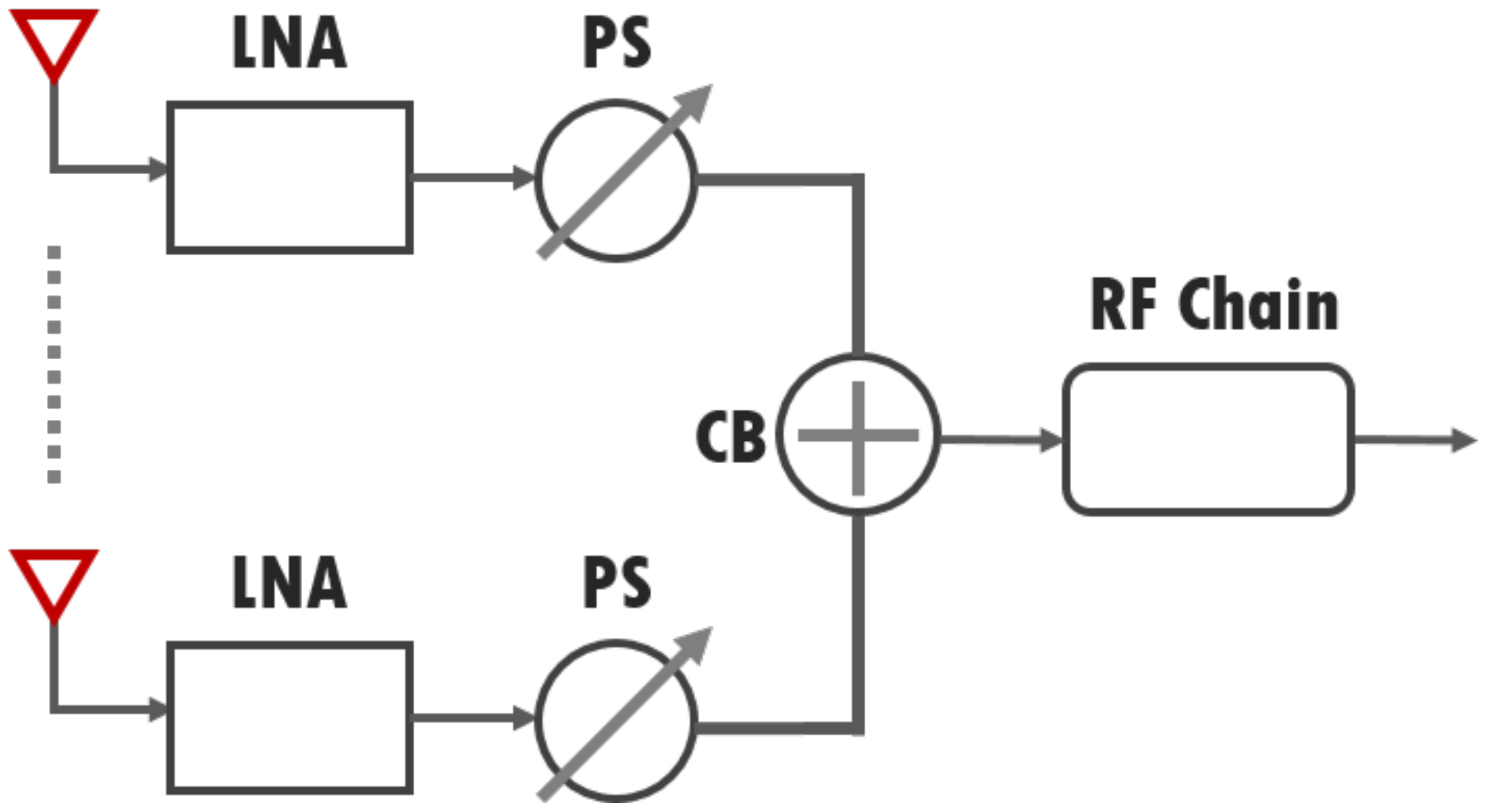
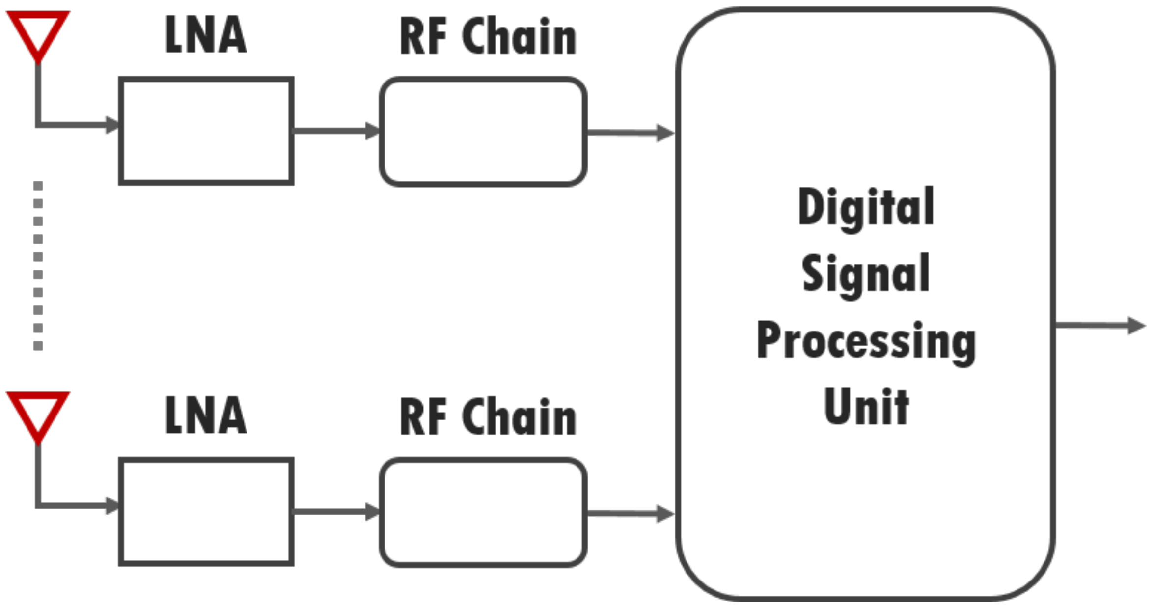
where σ ¯ S D is the average SNR between the source node and the destination node. In the ABF, the weight vector can be implemented by a low noise amplifier and phase shifter, and then the signals are integrated by combiner. However, in terms of the DBF the roles of the phase shifter and combiner are integrated in the digital signal processing unit. Thus, the energy consumption of the phase shifter is not considered in the DBF. The ABF structure (Figure 3) consists of the LNA, PS, and CB, which are the phase shifter and combiner, and the RF chain (RFC) is comprised of P B A S Baseband power consumption of the sensor board, P M I X Mixer, P S Y N Local Oscillator, P L N A Low Noise Amplifier, P F I L Filter, P I F A Intermediate Frequency Amplifier, and P A D C Analog-to-Digital Converter, respectively. The DBF structure is the same as Figure 4. The RX [40] of the ABF and the DBF can be expressed by:
P R X A B F = N A N T P L N A + P P S + P C B + P R F C .
P R X D B F = N A N T P L N A + P R F C
where N A N T is the number of antenna. To get the total energy consumption of both the ABF and the DBF Equations (18) and (19) are substituted for the RX of Equation (5).

3.3. Multi-Hop Scheme

The multi-hop network consists of a two-hop topology. Thus, two time slots are used for the multi-hop communication, which leads to the throughput reduction to more than half compared with the single-hop communication. The outage probability [33,41] of each link in a multi-hop scheme that is the same as cooperative and incremental cooperative schemes can be expressed by:
ρ i j = Pr σ i j < μ 1 Γ m + 1 m N μ P i γ i j m .
where μ = 2 θ R 1 where θ is constant, which is multiplied to increase threshold level because the distance between the source node and relay node is closer than the distance between the source node and the destination node is, N = N 0 B where N 0 is the noise power spectral density, and B is the bandwidth. The ρ i j is also used to cooperative and incremental cooperative schemes in common to get the outage probability for each channel.
As mentioned earlier, the relay node uses the same circuit board, which means it consumed the same energy as the source, relay, and destination node. Thus, the total energy consumption [42] on the multi-hop scheme is represented by:
E M H = ρ S R P A M P + P T X + P R X κ θ R b + 1 ρ S R 2 P A M P + 2 P T X + 2 P R X κ θ R b
where ρ S R is the outage probability between the source node and relay node and all terms are divided by θ because θ is multiplied to the spectral efficiency of the multi-hop SNR threshold. The first term considers the energy consumption when the relay node fails to decode the packet from source node at the relay node, and the second term considers the energy consumption when the relay node succeeds to decode and forward it to destination node.
The optimal transmitted power of multi-hop scheme that is also considered with the target outage probability can be obtained by:
ρ 0 P M H 2 m k 1 + k 2 P M H m + k 1 k 2 = 0
where k 1 = m N μ m Γ ( m + 1 ) γ S R m , k 2 = m N μ m Γ ( m + 1 ) γ R D m . Finally, by finding the roots of the polynomial, the optimal transmitted power is given.
In terms of throughput of the multi-hop scheme, it can be expressed by:
T M H = R 2 1 ρ S R 1 ρ R D
where ρ R D is the outage probability between the relay node and destination node, the spectral efficiency is half than that of the single-hop transmission due to using two time slots.

3.4. DF Scheme

The DF communication consists of two phases for the source node to send the packet to the destination node by cooperation with the relay node. In the first phase, the source node transmits a packet to the relay node and destination node, in the second phase the relay node transmits the packet from the source node to the destination node. Thus, the total energy consumption [42] on three nodes in DF communication can be obtained by:
E D F = ρ S R P A M P + P T X + 2 P R X κ θ R b + 1 ρ S R 2 P A M P + 2 P T X + 3 P R X κ θ R b .
where the first term means the energy consumption when the relay node fails to decode the packet from source node, and the second term means the energy consumption when the relay node succeeds to decode the packet and to carry out cooperative communication.
In the case of cooperative schemes, a multi-hop scheme finding the roots of the polynomial, the optimal transmitted power can be obtained by:
ρ 0 P D F 3 m k 1 k 3 + k 2 k 3 P D F m + k 1 k 2 k 3 = 0 .
where k 1 and k 2 are the same as mentioned above in multi-hop scheme, and k 3 = m N μ m Γ ( m + 1 ) γ S D m .
The DF throughput [34] can be expressed by:
T D F = R 2 1 ρ S D + R 2 ρ S D 1 ρ S R 1 ρ R D
where there are two terms, the first term means the throughput between the source node and the destination node, the second term means the throughput when communication is carried out by using relay node. The spectral efficiency of both terms is half due to the half-duplex constraint.

3.5. AF Scheme

The AF communication mechanism is similar to the DF. However, the relay node receives a signal from the source node, not to decode the signal but to amplify the signal and forward it to the destination node. Thus, the received signal at the destination node can be expressed by:
y i j = β P i h i j x + n i j
where β is amplification factor that is given by:
β = P i P i h s r 2 + N 0 .
According to this communication mechanism, the total energy consumption [43] of the AF can be expressed by:
E A F = P A M P + P T X + 2 P R X κ θ R b + P A M P * + P T X + P R X κ θ R b
where P A M P * = v P i P i γ S R + N is the transmission power from the relay node and γ S R is the pathloss between the source node and the relay node. The first term represents the energy consumption when the source node transmits a packet to the source node and destination node, and the second term is the energy consumption when the relay node conveys the packet.
In terms of the throughput of the AF, it is the same as the DF.

3.6. IDF Scheme

The IDF is the DF-based communication, which has three phases. In the first phase, the source node broadcasts to the relay and destination node. In the second phase, the destination node makes a decision whether to request the packet of the source node or not, and the destination node gives an ACK or a NACK to the relay node and the source node. In the third phase, according to the decision of the destination node, the relay node forwards the packet or keeps silent. Thus, the total energy consumption [42] of the IDF can be expressed by:
E I D F = 1 ρ S D ( P A M P + P T X + 2 P R X ) κ θ R b + ρ S D · ρ S R ( P A M P + P T X + 2 P R X ) κ θ R b + ρ S D · 1 ρ S R ( 2 P A M P + 2 P T X + 3 P R X ) κ θ R b .
where the first term shows when the destination node decodes the packet sent directly from the source node successfully, the second term shows the energy consumption when both of the relay node and the destination node fail to decode the packet from the source node, and the third term shows when the cooperative relaying works fully.
The IDF throughput can be obtained by:
T I D F = R 1 ρ S D + R 2 ρ S D 1 ρ S R 1 ρ R D
where the first term represents the throughput when the packet of the source is conveyed successfully to the destination node, and the second term represents the throughput when the packet is conveyed via the relay node to the destination node.

3.7. IAF Scheme

The transmission mechanism of the IAF scheme is similar with the IDF, however at the relay node the message is not decoded but amplified as the AF. Thus, the total energy consumption [43] is obtained by:
E I A F = P A M P + P T X + 2 P R X κ θ R b + ρ S D P A M P * + P T X + P R X κ θ R b
where the total energy consumption is almost the same as the AF, the outage probability factor is added between the source node and the destination node, which means according to the packet of the source node sent directly to the destination node the total energy should be reduced.
In terms of the IAF throughput, it is the same as the IDF.

4. Simulation Results

The energy consumption and the throughput analysis on beamforming, non-cooperative, and cooperative schemes in the aircraft channel environment are conducted by using Matlab 2018a to illustrate the theoretical analysis in this section. The real value of the circuit power consumption is referred by [31].
The performance metrics are total energy consumption and throughput, which are plotted below. In the case of the transmitted power the optimal transmitted power using Equations (11), (22) and (25) is applied to the single-hop (including the beamforming), the multi-hop, the cooperation (including the incremental cooperation) schemes, respectively. In addition, the distance requirement is based on ITU-R M.2283 which is that the distance between two nodes is a maximum of 15 m. Thus, we suppose that the distance from the source node to the destination node is fixed at 10 m, and the position of the relay node is at the middle point between the source node and the destination node in which each distance is 5 m. All the nodes communicate each other in the NLoS channel environment in which the received node uses the SC technique to gain the greatest SNR from scattered signals except the beamforming scheme. The parameters are summarized by Table 2.
In Figure 5, the optimal transmitted power of the beamforming, the single-hop, the multi-hop, and the cooperative schemes shows the distance from the source node to the destination node. This factor is important because in ITU-R M.2283 there is the requirement regarding the transmitted power of wireless avionics intra-communication to prevent from some interference among the wireless communication nodes. Thus, the transmitted power based on the requirement should be below 10 mW. According to the result in Figure 5, the transmitted power requirement was satisfied in all schemes at a distance of 10 m in which the optimal powers of the single-hop, the multi-hop, and the cooperative power were 1.117, 0.821, and 0.053 mW, respectively. Thus, we can know that cooperative schemes use lower power 95% at 10 m than the single-hop scheme. Besides, at a distance of 15 m the powers of the single-hop, the multi-hop, and the cooperative schemes were 2.764, 1.962, and 0.127 mW, respectively, which are not over the requirement of 10 mW. For the beamforming schemes we used the number of three antennae in this paper.
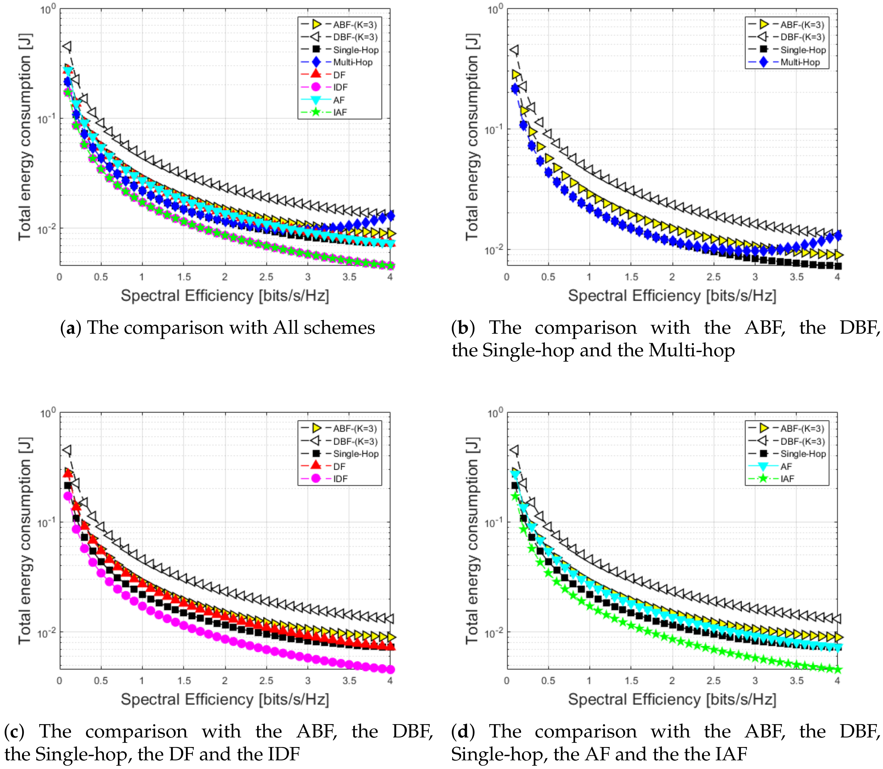
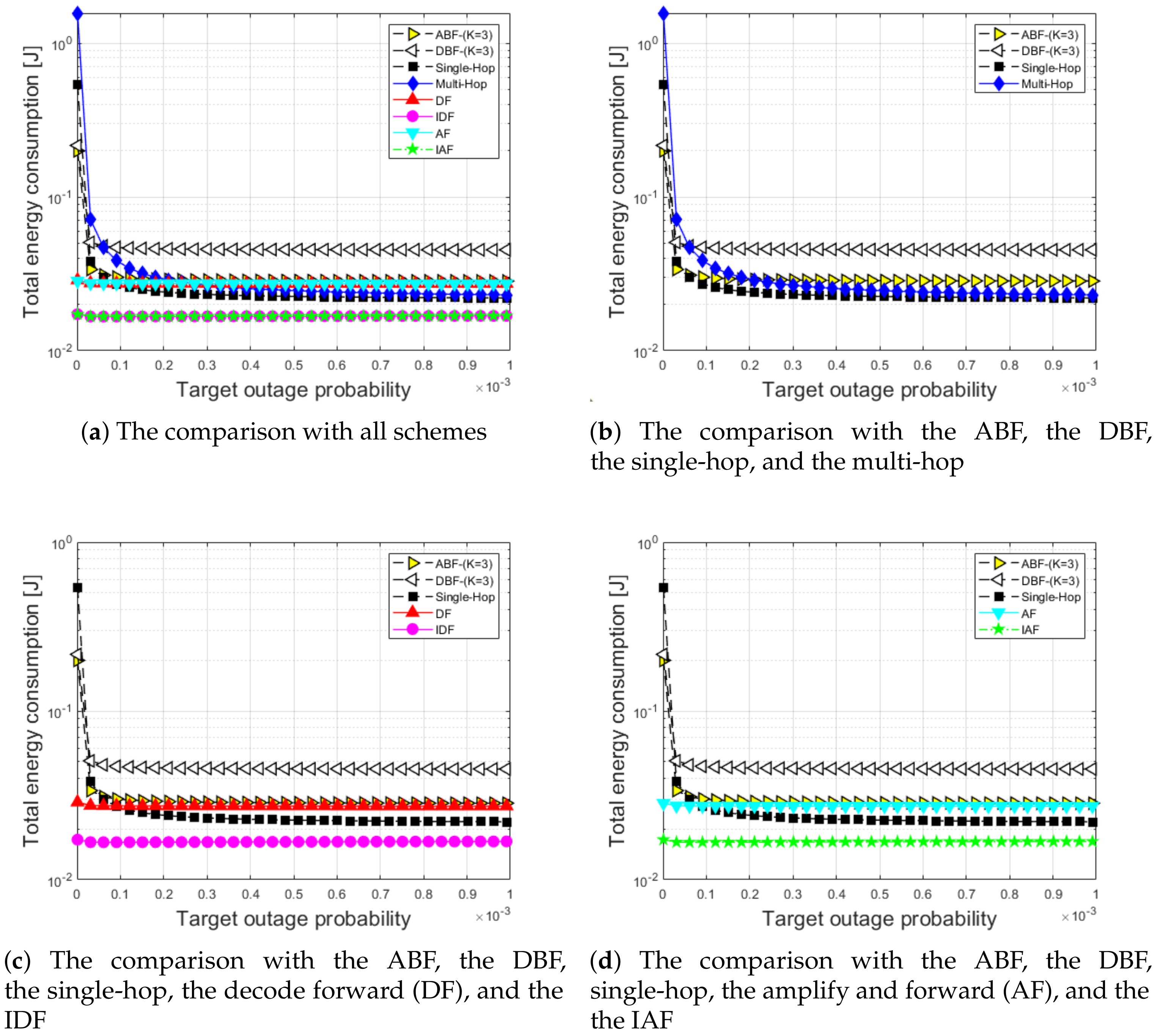
In Figure 6 and Figure 7, the simulation results of the total energy consumption are presented regarding eight schemes according to spectral efficiency and target outage probability. Figure 6 and Figure 7 show the result based on Equations (5), (21), (24), (29), (30), and (32), which are used to represent total energy consumption in the aircraft channel model regarding the ABF, the DBF, the single-hop, the multi-hop, the DF, the AF, the IDF, and the IAF schemes, respectively.
As shown in Figure 6, the values of total energy consumption of the ABF, the DBF, the single-hop, the multi-hop, the DF, the AF, the IDF, and the IAF schemes were 28.74, 45.62, 22.032, 21.879, 27.273, 16.917, 27.277, and 16.918 mJ at a spectral efficiency of 1, respectively. In addition, at a spectral efficiency of 4 the schemes consumed a total energy of 8.982, 13.204, 7.306, 13.037, 7.104, 4.378, 7.105, and 4.378 mJ, respectively. According to the result, it shows the IDF and the IAF schemes consumed lower total energy in an overall spectral efficiency range than the other schemes in which the IDF and IAF schemes compared with the DBF scheme could save a total energy consumption of 66.8% at a spectral efficiency of 2. The reason is that the the IDF, the IAF schemes could save the time slot according to a feedback from the destination node. In other words, the IDF, the IAF schemes coujld save energy consumption by the channel environment. On the other hand, the DBF scheme used a higher total energy consumption in an overall spectral efficiency than the others, due to RF chains depending on the number of the equipped antenna K. In the case of the total energy consumption of the multi-hop scheme, it was similar with the ABF, the single-hop, the DF, and the AF schemes. However, when the spectral efficiency was high, the total energy consumption increased gradually. The reason was that the optimal transmitted power was applied to the amplifier P A M P . Thus, according to the related equations the optimal transmitted power of single-hop, multi-hop, and cooperative schemes was different from each other due to a different impact of the channel response. Therefore, when the spectral efficiency was over around 3, the transmitted power of the multi-hop scheme increased more than other schemes, which caused the total energy consumption of multi-hop scheme to increase as well.
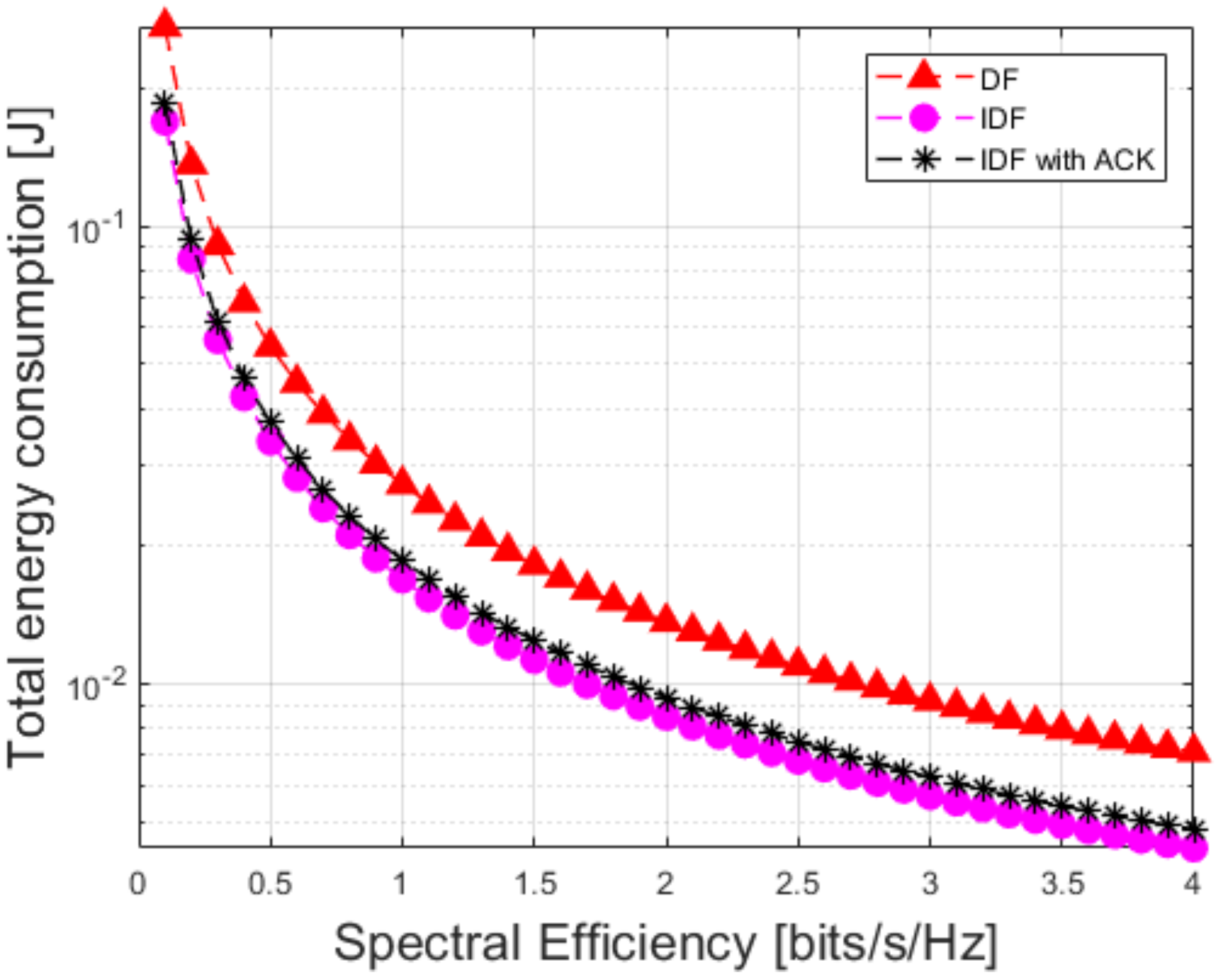
In Figure 7, the impact of the ACK is displayed at the IDF scheme, when the ACK or the NACK messages were sent from the destination node. The maximum energy consumption was 10% of total energy consumption of the IDF, which was estimated [42]. According to the result, the energy consumption of ACK was small enough to neglect, and the IDF performance still maintained better than the others in Figure 6 in which the IDF with ACK compared with the DF at a spectral efficiency of 2 could save a total energy consumption of 7.11 mJ more.
In Figure 8, in the cases of the ABF, the DBF, single-hop, and multi-hop schemes the total energy consumption increased in the target outage probability range between 10 6 and 3.1 × 10 5 because the schemes needed more energy to satisfy the high target probability. However, the growth ratio of total energy consumption of the cooperative schemes was low due to a complement by the relay node which played a role as a redundancy in which the incremental cooperation schemes compared with the DBF could save the total energy consumption of 61.9% more at the target outage probability 1 × 10 3 . Whereas, the total energy consumption of all the schemes were constant when the target outage probability approached 10 3 . The reason was that the BPSK modulation was applied to all the schemes and the nodes were deployed within a maximum of 10 m [6].
In Figure 9 and Figure 10, we present the throughput and normalized throughput performance as the spectral efficiency regarding eight schemes at SNR 0 dB. In Figure 9, the beamforming scheme had a better performance over the other scheme at a spectral efficiency from 0.1 to 4 in which at a spectral efficiency of 1 the beamforming, the single-hop, the multi-hop, the cooperation, and the incremental cooperation schemes had 0.7165, 0.3678, 0.1041, 0.2497, and 0.4337 [bits/s/Hz], respectively. According to the result, the throughput performance of the beamforming scheme achieved 39.4% better than the incremental cooperation scheme. The reason was that the beamforming scheme had diversity gain that was proportional to K-element antenna, which means that the performance increased relatively by the number of antenna. In addition, the multi-hop scheme had the lowest performance because the multi-hop scheme always used two slots and the coverage was almost enough by one hop. In the case of the single-hop scheme the throughput performance was higher than the DF, the AF schemes in spectral efficiency ranged between 0.1 and 4 because SNR was strong enough to transmit a signal.
In Figure 10, the performance of throughput is normalized by each scheme energy. The result in Figure 10 shows that the IDF outperform the other schemes in spectral efficiency ranged between 0.1 and 0.8 in which at a spectral efficiency of 0.8, the IDF had a performance of 18.165 [kbits/s/Hz/J]. Whereas, the multi-hop scheme had the worst performance at a spectral of 0.8 in which it had a performance of 5.783 [kbits/s/Hz/J]. In addition, the performance gap between the IDF and ABF at a spectral efficiency of 0.8 was only different at 0.1%, which means the performance aws almost same. As the spectral efficiency increased more than 0.9, the ABF scheme had the best performance in a spectral efficiency range from 0.9 to 4 in which the performance values of the ABF, the DBF, the IAF, and the IDF schemes at a spectral efficiency of 1 were 25.994, 16.264, 19.057, and 21.899 [kbits/s/Hz/J], respectively. According to the result, the performance of the ABF achieved 15.7% better than the IDF at a spectral efficiency of 1. The reason was that diversity gain of the ABF scheme gave a better impact to the normalized throughput performance, which means that the gain of the the ABF scheme was stronger to the point where it complemented the energy consumption. Whereas, the multi-hop scheme was lower than the others between a spectral efficiency of 0.4 and 4 due to the short distance between the source node and destination node. Finally, the normalized throughput performance was maximized by using both of the IDF scheme or the ABF scheme according to spectral efficiency.
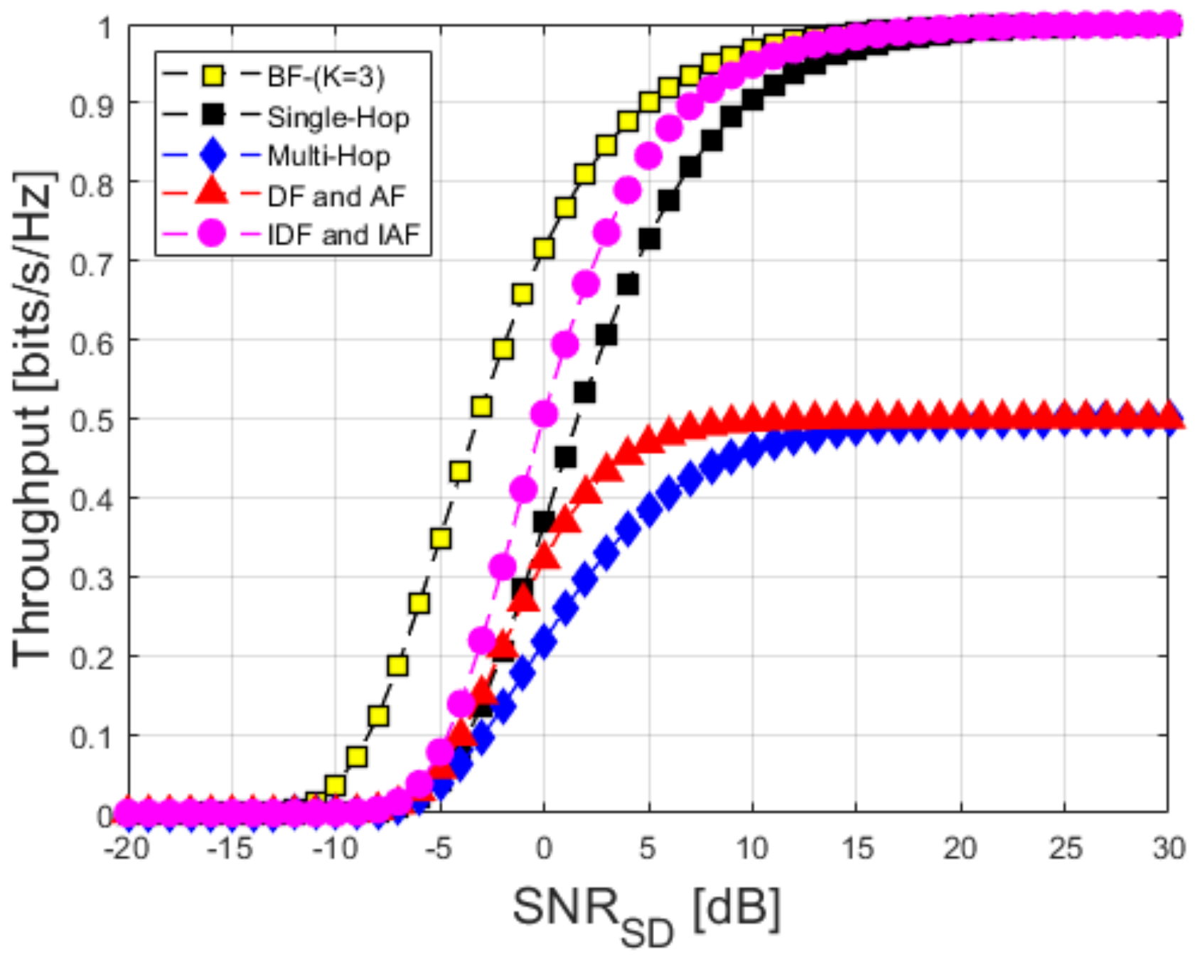
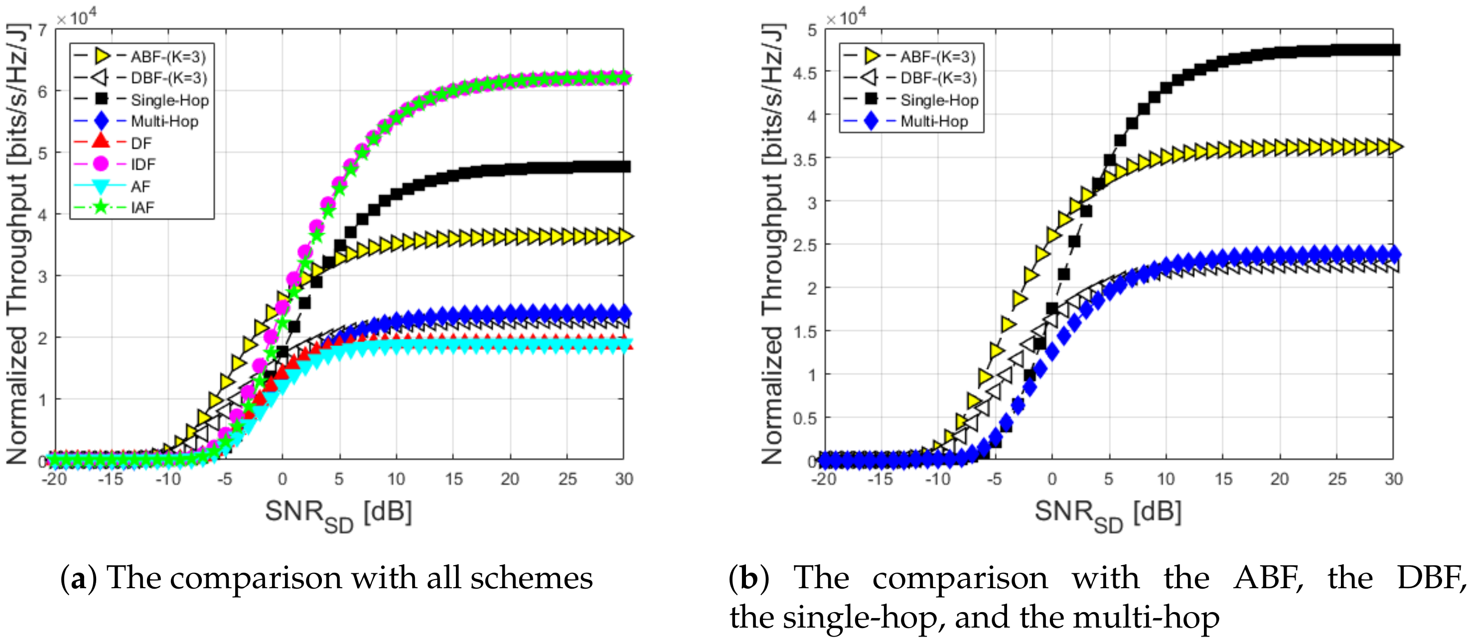
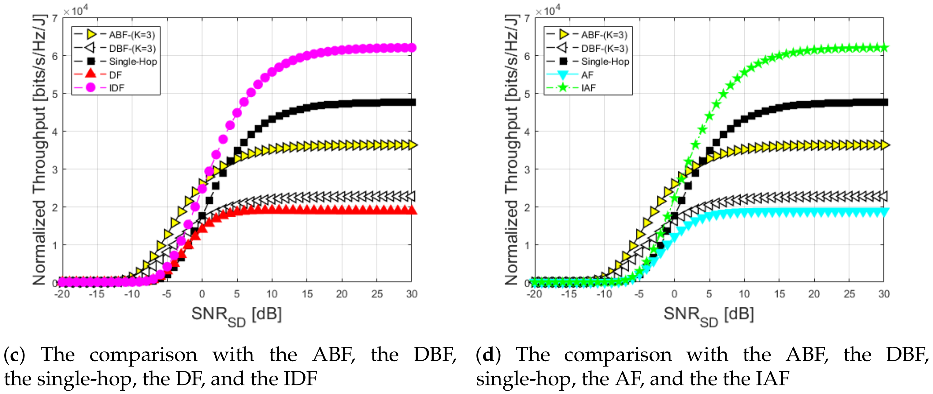
In Figure 11 and Figure 12, we present the throughput as SNR with eight schemes. In Figure 11, we show that the beamforming scheme outperformed the other schemes in overall a SNR range between −20 and 30 SNR range. The reason was that the beamforming scheme kept a very low outage probability compared with the single-hop scheme. At 0 dB SNR, the throughput values of the beamforming, the single-hop, the multi-hop, the cooperation, and the incremental cooperation schemes were 0.7165, 0.3678, 0.1041, 0.2497, and 0.4337 [bits/s/Hz], respectively. According to the result, the beamforming scheme achieved 85.4% better than the multi-hop scheme. As mentioned earlier, the incremental cooperative schemes used one or two slot up to the destination node feedback, which means that it always had the better throughput performance than the single-hop scheme. In the case of the single-hop scheme, it had a good performance when it approached a high SNR because it was strong enough to deliver a signal, and then the multi-hop and the DF, the AF schemes had the same performance in high SNR between 19 and 30 dB in which those have half of the single-hop performance because those always used two slots. In Figure 12, throughput was normalized by each scheme energy consumption. In low SNR ranged between −20 and 1 dB, the ABF scheme was more robust than the others in which at a SNR of 0 dB the performance values of the ABF, the DBF, the single-hop, the multi-hop, the DF, the IDF, the AF, and the IAF were 25.994, 16.264, 17.505, 6.374, 11.378, 21.899, 9.381, and 19.057 [kbits/s/Hz/J], respectively. According to the result, the ABF scheme achieved 75.4% better than the multi-hop scheme. Whereas, in a high SNR range between 2 and 30 dB the IDF scheme was better than the other schemes including the beamforming scheme because the incremental approach and decode-and-forward mechanism were advantageous to save the energy consumption. In addition, at SNR 10 dB the performance values of the ABF, the DBF, the single-hop, the multi-hop, the DF, the IDF, the AF, and the IAF were 35.089, 21.954, 43.057, 20.936, 18.947, 55.422, 18.52, and 55.237 [kbits/s/Hz/J], respectively. Based on the result, the IDF achieved 62.2% better than the multi-hop scheme. In the case of the beamforming scheme, it had a relatively high energy consumption in a high SNR. Thus, the normalized throughput performance of the ABF and the DBF schemes had a lower performance than the IDF scheme. In terms of the DF, the AF schemes had a lower performance than the multi-hop scheme in a high SNR ranged between 8 and 30 dB because they considered additionally the source and destination node link, which means that the destination node spent one more time to decode the source node signal.

5. Conclusions and Future Works

In this paper, we investigated beamforming, single-hop, multi-hop, and cooperative schemes for the aircraft wireless sensor networks and perform energy consumption and throughput analysis in the aircraft channel model. The aircraft channel was modeled by referring ITU-R M.2283, which consists of path loss, shadowing fading, and multi-path fading. The optimal transmitted power was applied to the eight scheme, which satisfied the transmitted power requirement except for multi-hop scheme. The performance of the total energy consumption and throughput was shown. According to the result, the incremental cooperative scheme outperformed by 66.8% better at a spectral efficiency of 2 than the DBF scheme in terms of energy consumption metric in which the beamforming scheme had a relatively high total energy consumption because the total energy consumption of the ABF and the DBF schemes increased in proportion to K-element antenna. Whereas, in terms of throughput metric in the overall SNR range from −20 to 30 dB, the beamforming scheme had the best performance in which the beamforming scheme at SNR 0 dB achieved 85.4% better than the multi-hop scheme. In the case of the single-hop scheme, it had a similar performance in high a SNR range from 10 to 30 dB because the signal was strong enough to delivery successfully to the destination node. Finally, in terms of normalized throughput metric in a low SNR range between −20 and 1 dB the ABF scheme had a better performance than the others in which the ABF at SNR 0 dB achieved 75.4% better than the multi-hop scheme. Whereas, in a high SNR range between 2 and 30 dB the IDF scheme had a better performance over the others in which the IDF at SNR 10 dB achieved 62.2% better than the multi-hop scheme. To apply to the aircraft wireless sensor networks, not only should the energy consumption be considered, but also the reliability for safety should be guaranteed, which is taken into account by the packet delay (including transmission, medium access, and queueing) and the packet loss (including shadow fading, multipath fading, doppler shift, and interference). For example, if one of sensors or one of actuators do not work due to some interference, it could lead to a major accident. Thus, the reliability of the wireless communication should be verified. One of methods to evaluate those factors became BER (bit trror rate), PER (packet error rate), RMSE (root mean square error), etc. For future work we intend to survey the reliability requirement for the aircraft, and based on the requirement to design a system model and evaluate it by using a NS2 simulation tool in terms of diverse wireless communication schemes.

Author Contributions

Data Curation, Methodology S.-H.K.; Formal analysis J.-W.K.; writing—review and editing D.-S.K. All authors have read and agreed to the published version of the manuscript.

Funding

This research received no external funding.

Acknowledgments

This research was supported by Basic Science Research Program, Priority Research Centers Program through the National Research Foundation of Korea (NRF), and the Grand Information Technology Research Center support program through the IITP (IITP-2020-2020-0-01612, 2019R1I1A1A01063895, 2018R1A6A1A03024003).

Conflicts of Interest

The authors declare no conflict of interest.

Notations

SymbolDescription
LTotal channel response
γ i j Path loss between node i and node j
YShadowing fading
XMulti-path fading
C 1 Constant offset of path loss
dDistance between transmitter and receiver
fCenter frequency
P i Transmitted power from i node
xPacket from the source node
Ψ ( * ) Incomplete gamma function
Γ ( * ) Complete gamma function
BBandwidth
N 0 Thermal noise power spectral density
μ SNR threshold
ρ Outage probability
wWeight vector
RSpectral efficiency
κ Packet size
R b Bit rate
V D Source voltage
I 0 Source current
f c o r Corner frequency
CParasitic capacitance
L c Minimum channel length
δ Correcting factor
vPower amplifier efficiency
ω Drain efficiency
τ Peak to average ratio
P E L Basic power consumption to run a sensor board
P A M P Amplifier power consumption
P T X Total transmitted RF power consumption
P R X Total received RF power consumption
P B A S Baseband power consumption
P M I X Mixer power consumption
P S Y N Synthesizer power consumption
P F I L Filter power consumption
P D A C Digital analog converter power consumption
P L N A Low noise amplifier power consumption
P I F A Intermediate frequency amplifier power consumption
P A D C Analog digital power consumption
P S Y N Synthesizer power consumption

References

  1. Youn, W.; Yi, B. Software and hardware certification of safety-critical avionic systems: A comparison study. Comput. Stand. Interfaces 2014, 36, 889–898. [Google Scholar] [CrossRef]
  2. Kiepert, J.; Loo, S.M.; Klein, D.; Pook, M. Wireless sensor networks for aircraft cabin environmental sensing. In Proceedings of the 41st International Conference on Environmental Systems, Portland, OR, USA, 17–21 July 2011; pp. 1–8. [Google Scholar]
  3. Pook, M.; Loo, S.M.; Kiepert, J. Monitoring of the aircraft cabin environment via a wireless sensor network. In Proceedings of the 42st International Conference on Environmental Systems, San Diego, CA, USA, 15–19 July 2012; pp. 1–9. [Google Scholar]
  4. Hall, J.A.; Kiepert, J.; Pook, M.; Loo, S.M. Monitoring of aircraft cabin particulate matter concentrations using a wireless sensor network. In Proceedings of the 43st International Conference on Environmental Systems, Vail, CO, USA, 14–18 July 2013; pp. 1–7. [Google Scholar]
  5. Kim, S.; Kim, J.; Kim, D. Performance analysis of Cooperative Schemes for Wireless Sensor Network of Aircraft. In Proceedings of the 11th International Conference on Ubiquitous and Future Networks (ICUFN), Zagreb, Croatia, 2–5 July 2019; pp. 642–645. [Google Scholar]
  6. ITU. Technical Characteristics and Spectrum Requirements of Wireless Avionics Intra-Communications Systems to Support Their Safe Operation. ITU-R M.2283. 2013. Available online: https://www.itu.int/pub/R-REP-M.2283-2013 (accessed on 4 April 2014).
  7. Long, N.B.; Kim, D. TDMA-based efficient cooperative relaying selection scheme in multi-hop wireless networks. Comput. Stand. Interfaces 2017, 53, 39–47. [Google Scholar] [CrossRef]
  8. Quang, P.T.A.; Kim, D. Enhancing Real-Time Delivery of Gradient Routing for Industrial Wireless Sensor Networks. IEEE Trans. Ind. Inform. 2012, 8, 61–68. [Google Scholar] [CrossRef]
  9. Gao, S.; Dai, X.; Hang, Y.; Guo, Y.; Ji, Q. Airborne Wireless Sensor Networks for Airplane Monitoring System. Wirel. Commun. Mob. Comput. 2018, 2018, 1–18. [Google Scholar] [CrossRef]
  10. Vujic, D. Wireless sensor networks applications in aircraft structural health monitoring. J. Appl. Eng. Sci. 2015, 13, 79–86. [Google Scholar] [CrossRef]
  11. Sahmoudi, M.; Amin, M.G. Optimal Robust Beamforming for Interference and Multipath Mitigation in GNSS Arrays. In Proceedings of the IEEE International Conference on Acoustics, Speech and Signal Processing (ICASSP), Honolulu, HI, USA, 15–20 April 2007; pp. 693–696. [Google Scholar]
  12. Crismani, A.; Toumpis, S.; Schilcher, U.; Brandner, G.; Bettstetter, C. Cooperative Relaying Under Spatially and Temporally Correlated Interference. IEEE Trans. Veh. Technol. 2015, 64, 4655–4669. [Google Scholar] [CrossRef] [Green Version]
  13. Park, P.; Coleri Ergen, S.; Fischione, C.; Lu, C.; Johansson, K.H. Wireless Network Design for Control Systems: A Survey. IEEE Commun. Surv. Tutor. 2018, 20, 978–1013. [Google Scholar] [CrossRef]
  14. ITU. Final Acts WRC-15. World Radiocommunication Conference. 2015. Available online: http://www.itu.int/pub/R-ACT-WRC.12-2015 (accessed on 5 April 2016).
  15. IEEE 802.15 Working Group. IEEE Std. 802.15.4-2003, IEEE Standard for Information Technology Telecommunications and Information Exchange between Systems Local and Metropolitan Area Networks Specific Requirements—Part 15.4: Wireless Medium Access Control (MAC) and Physical Layer (PHY) Specifications for Low Rate Wireless Personal Area Networks (LR-WPANs). IEEE. 2003. Available online: https://ieeexplore.ieee.org/servlet/opac?punumber=8762 (accessed on 1 October 2003).
  16. IEEE 802.11 Working Group. IEEE Standard Part 11: Wireless Lan Medium Access Control (MAC) and Physical Layer (PHY) Specifications. IEEE. 2012. Available online: https://ieeexplore.ieee.org/servlet/opac?punumber=7786993 (accessed on 14 December 2016).
  17. IEEE 802.15 Working Group. IEEE Standard for Information Technology Telecommunications and Information Exchange between Systems Local and Metropolitan Area Networks Specific Requirements—Part 15.1: Wireless Medium Access Control (MAC) and Physical Layer (PHY) Specifications for Wireless Personal Area Networks (WPANs). IEEE. 2002. Available online: https://ieeexplore.ieee.org/servlet/opac?punumber=8287782 (accessed on 7 February 2018).
  18. Nwadiugwu, W.P.; Kim, D. Ultrawideband Network Channel Models for Next-Generation Wireless Avionic System. IEEE Trans. Aerosp. Electron. Syst. 2020, 56, 113–129. [Google Scholar] [CrossRef]
  19. Gao, S.; Yang, W.; Ji, Q. Research on Path Loss for an Airplane Wing Wireless Monitoring System. IEEE Antennas Wirel. Propag. Lett. 2018, 17, 1090–1094. [Google Scholar] [CrossRef]
  20. Fu, H.; Khodaei, Z.S.; Aliabadi, M.H.F. An Event-Triggered Energy-Efficient Wireless Structural Health Monitoring System for Impact Detection in Composite Airframes. IEEE Internet Things J. 2019, 6, 1183–1192. [Google Scholar] [CrossRef]
  21. Gao, S.; Shang, F.; Du, C. Design of Multichannel and Multihop Low-Power Wide-Area Network for Aircraft Vibration Monitoring. IEEE Trans. Instrum. Meas. 2019, 68, 4887–4895. [Google Scholar] [CrossRef]
  22. Baltaci, A.; Zoppi, S.; Kellerer, W.; Schupke, D. Evaluation of Cellular Technologies for High Data Rate WAIC Applications. In Proceedings of the IEEE International Conference on Communications (ICC), Shanghai, China, 20–24 May 2019; pp. 1–6. [Google Scholar]
  23. Bang, I.; Nam, H.; Chang, W.; Kim, T.; Woo, J.; Kim, C.; Ban, T.; Park, P.; Jung, B. Channel Measurement and Feasibility Test for Wireless Avionics Intra-Communications. Sensors 2019, 19, 1294. [Google Scholar] [CrossRef] [PubMed] [Green Version]
  24. Krichen, D.; Abdallah, W.; Boudriga, N. On the design of an embedded wireless sensor network for aircraft vibration monitoring using efficient game theoretic based MAC protocol. Ad Hoc Netw. 2017, 61, 1–15. [Google Scholar] [CrossRef]
  25. Notay, J.K.; Safdar, G.A. A wireless sensor network based structural health monitoring system for an airplane. In Proceedings of the 17th International Conference on Automation and Computing, Huddersfield, UK, 10 September 2011; pp. 240–245. [Google Scholar]
  26. Wu, J.; Yuan, S.; Zhou, G.; Ji, S.; Wang, Z.; Wang, Y. Design and evaluation of a wireless sensor network based aircraft strength testing system. Sensors 2009, 9, 4195–4210. [Google Scholar] [CrossRef] [PubMed]
  27. Balanis, C.A. Antenna Theory: Analysis and Design; Wiley Press: Hoboken, NJ, USA, 2016. [Google Scholar]
  28. Wang, Z.; Giannakis, G.B. A simple and general parameterization quantifying performance in fading channels. IEEE Trans. Commun. 2003, 51, 1389–1398. [Google Scholar] [CrossRef] [Green Version]
  29. Manhas, E.B.; Pellenz, M.E.; Brante, G.; Souza, R.D.; Rosas, F. Energy Efficiency Analysis of HARQ with Chase Combining in Multi-Hop Wireless Sensor Networks. In Proceedings of the IEEE Symposium on Computers and Communications (ISCC), Funchal, Portugal, 23–26 June 2014; pp. 1–6. [Google Scholar]
  30. Rayel, O.K.; Rebelatto, J.L.; Souza, R.D.; Uchoa-Filho, B.F.; Li, Y. Energy efficiency of network coded cooperative communications in Nakagami-m fading. IEEE Signal Process. Lett. 2013, 20, 960–963. [Google Scholar] [CrossRef]
  31. Cui, S.; Goldsmith, A.J.; Bahai, A. Energy-Constrained Modulation Optimization. IEEE Trans. Commun. 2015, 4, 2349–2360. [Google Scholar]
  32. Liu, H.C.; Min, J.S.; Samueli, H. A low-power baseband receiver IC for frequency-hopped spread spectrum communications. IEEE J. Solid State Circuits 1996, 31, 384–394. [Google Scholar]
  33. Brante, G.; Souza, R.D.; Vandendorpe, L. Battery-Aware Energy Efficiency of Incremental Decode and Forward with Relay Selection. In Proceedings of the IEEE Wireless Communications and Networking Conference (WCNC), Shanghai, China, 1–4 April 2012; pp. 1108–1112. [Google Scholar]
  34. Alves, H.; Souza, R.D. Selective Decode-and-Forward Using Fixed Relays and Packet Accumulation. IEEE Commun. Lett. 2011, 15, 707–709. [Google Scholar] [CrossRef]
  35. Winters, J.H. The diversity gain of transmit diversity in wireless systems with Rayleigh fading. IEEE Trans. Veh. Technol. 1998, 47, 119–123. [Google Scholar] [CrossRef]
  36. Kim, C.J.; Kim, Y.S.; Jeong, G.Y.; Mun, J.K.; Lee, H.J. SER analysis of QAM with space diversity in Rayleigh fading channels. ETRI J. 1996, 17, 25–35. [Google Scholar] [CrossRef]
  37. Akbari, M.; Manesh, M.R.; El-Saleh, A.A.; Reza, A.W. Receiver diversity combining using evolutionary algorithms in rayleigh fading channel. Sci. World J. 2014, 2014, 1–11. [Google Scholar] [CrossRef] [PubMed] [Green Version]
  38. Barry, J.R.; Lee, E.A.; Messerschmitt, D.G. Digital Communication; Springer Science and Business Media Press: Berlin, Germany, 2012. [Google Scholar]
  39. Goldsmith, A. Wireless Communications; Cambridge University Press: Cambridge, UK, 2005. [Google Scholar]
  40. Abbas, W.B.; Gomez-Cuba, F.; Zorzi, M. Millimeter Wave Receiver Efficiency: A Comprehensive Comparison of Beamforming Schemes With Low Resolution ADCs. IEEE Trans. Wirel. Commun. 2017, 16, 8131–8146. [Google Scholar] [CrossRef] [Green Version]
  41. Kakitani, M.; Brante, G.; Souza, R.D.; Munaretto, A.; Imran, M.A. Energy efficiency of some non-cooperative, cooperative and hybrid communication schemes in multi-relay WSNs. Wirel. Netw. 2013, 19, 1769–1781. [Google Scholar] [CrossRef] [Green Version]
  42. Brante, G.; Kakitani, M.T.; Souza, R.D. Energy Efficiency Analysis of Some Cooperative and Non-Cooperative Transmission Schemes in Wireless Sensor Networks. IEEE Trans. Commun. 2011, 59, 2671–2677. [Google Scholar] [CrossRef]
  43. Kakitani, M.T.; Brante, G.; Souza, R.D.; Imran, M.A. Energy efficiency of amplify-and-forward, repetition coding and parallel coding in short range communications. In Proceedings of the 30th International Conference on Telecommunications and Signal Processing (TSP), Prague, Czech Republic, 3–4 July 2012; pp. 212–216. [Google Scholar]
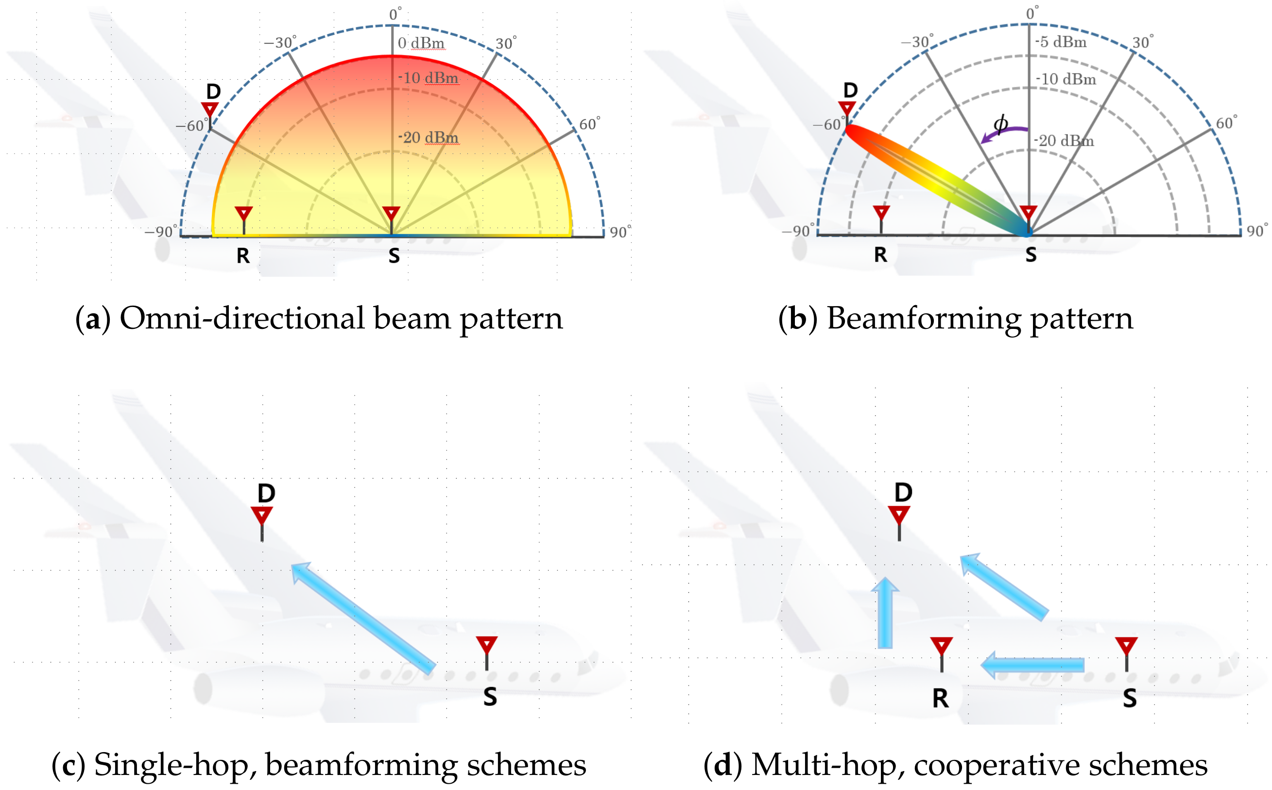
Figure 1. Examples of the system model.
Applsci 10 04374 g001
Figure 2. Example of a structure of the combining block diagram.
Applsci 10 04374 g002
Figure 3. Block diagram of the analog beamforming (ABF).
Applsci 10 04374 g003
Figure 4. Block diagram of the digital beamforming (DBF).
Applsci 10 04374 g004
Figure 5. Optimal transmitted power.
Applsci 10 04374 g005
Figure 6. Spectral efficiency vs. total energy consumption.
Applsci 10 04374 g006
Figure 7. Impact of ACK (acknowledgement) energy consumption.
Applsci 10 04374 g007
Figure 8. Target outage probability vs. total energy consumption.
Applsci 10 04374 g008
Figure 9. Throughput vs. spectral efficiency.
Applsci 10 04374 g009
Figure 10. Normalized throughput vs. spectral efficiency.
Applsci 10 04374 g010
Figure 11. Throughput vs. SNR.
Applsci 10 04374 g011
Figure 12. Normalized throughput vs. SNR.
Applsci 10 04374 g012aApplsci 10 04374 g012b
Table 1. Path loss parameters in the aircraft.
GroupGroup Namekn C 1 [dB]
AIntra-Flight Deck2.452.00189.8
BInter-Cabin2.093.46167.5
CInter-Cabin-to-Lower Lobe1.862.49124.5
DInter-Cabin-to-Exterior1.862.12118.2
EInter-Cabin-to-Landing Gear1.591.5177.9
FInter-Exterior1.952.31142.5
Table 2. Parameter setup.
ParameterParameter Value
BPSK modulationM = 2
Center frequency f c = 4.3 GHz
BandwidthB = 10 Kbps
Target outage probability ρ 0 = 10 3
Packet size κ = 1024 bit
Shadowing fading ϵ = 4 dB
Distance from S to Dd = 10 m
Number of antennaK = 3
Drain efficiency ω = 0.35
Peak to average ratio τ = 1.761 dB
Source voltage V D = 3 V
Source current I 0 = 10 μ A
Parasitic capacitanceC = 1 pF
Corner frequency f c o r = 1 MHz
Minimum channel length L C = 0.5 μ m
Filter power consumption P F I L = 2.5 mW
Synthesizer power consumption P S Y N = 50 mW
IFA power consumption P I F A = 3 mW
LNA power consumption P L N A = 20 mW