Author Contributions
Conceptualization, T.S.G. and C.-S.L.; data curation, T.S.G., B.-Y.L., J.S.L. and C.-S.L.; formal analysis, B.-Y.L. and C.-S.L.; funding acquisition, T.S.G., J.S.L. and C.-S.L.; investigation, T.S.G., B.-Y.L. and C.-S.L.; methodology, T.S.G., B.-Y.L. and C.-S.L.; project administration, T.S.G., J.S.L. and C.-S.L.; resources, T.S.G. and J.S.L.; software, B.-Y.L.; supervision, J.S.L. and C.-S.L.; validation, T.S.G., B.-Y.L. and C.-S.L.; visualization, B.-Y.L.; writing—original draft, T.S.G. and B.-Y.L.; writing—review and editing, T.S.G., B.-Y.L., J.S.L. and C.-S.L. All authors have read and agreed to the published version of the manuscript.
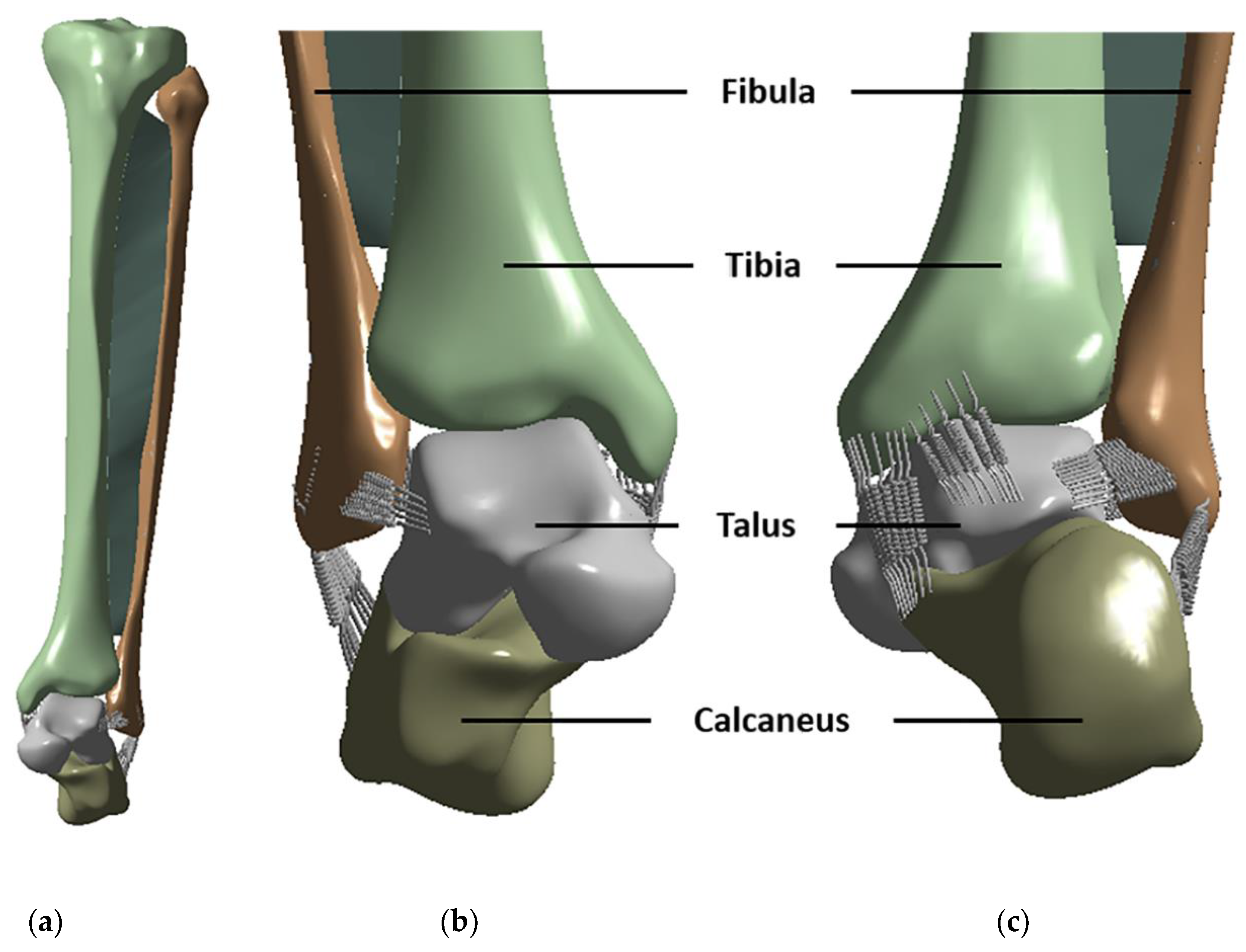
Figure 1.
3D models of the ankle bone and ligaments: (a) frontal view, (b) anterior ligaments, and (c) posterior ligaments.
Figure 1.
3D models of the ankle bone and ligaments: (a) frontal view, (b) anterior ligaments, and (c) posterior ligaments.
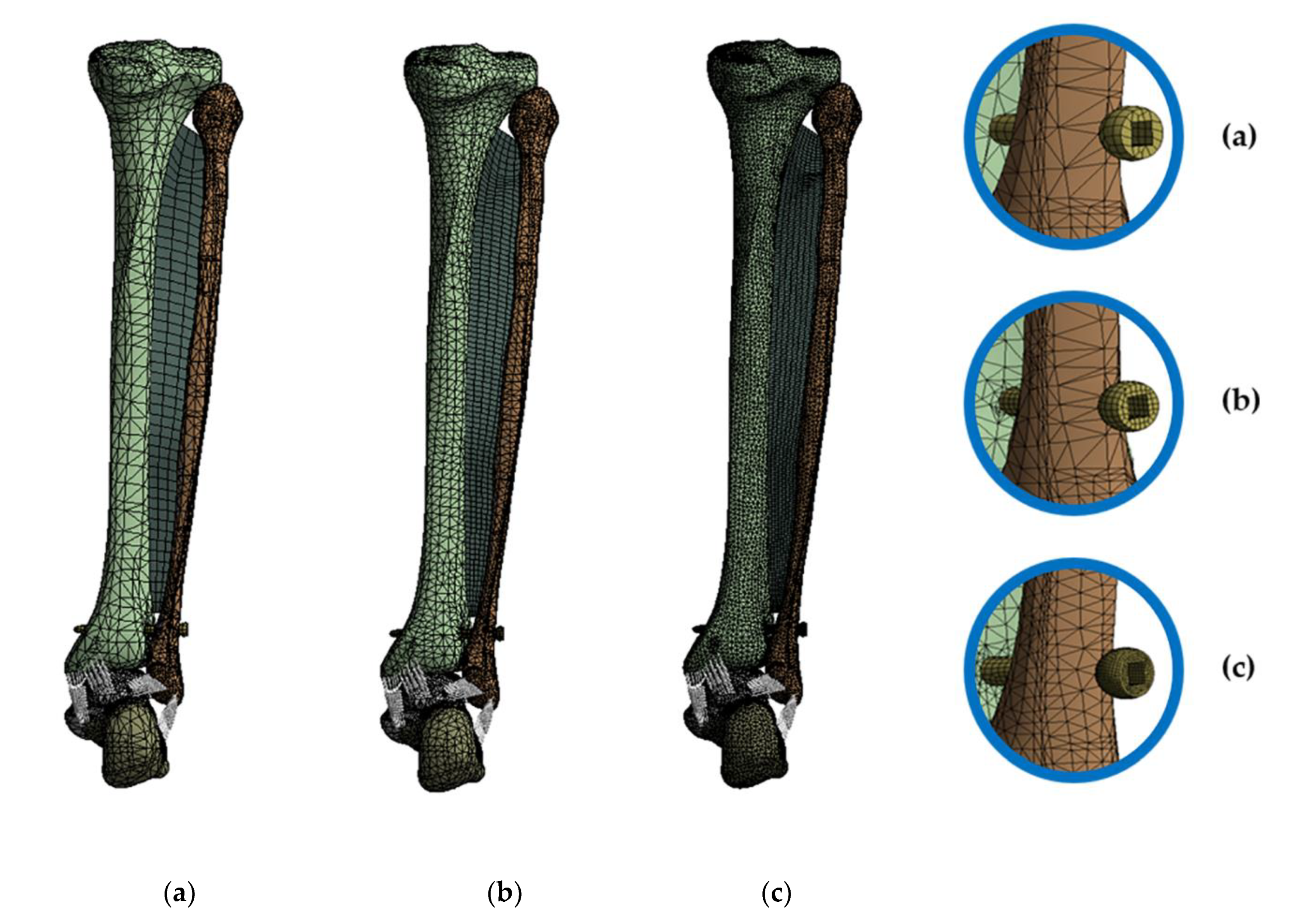
Figure 2.
Classification according to the mesh densities to evaluate the sensitivity of the elements: (a) shows the coarse mesh, (b) shows the medium mesh, and (c) shows the image of the fine mesh.
Figure 2.
Classification according to the mesh densities to evaluate the sensitivity of the elements: (a) shows the coarse mesh, (b) shows the medium mesh, and (c) shows the image of the fine mesh.
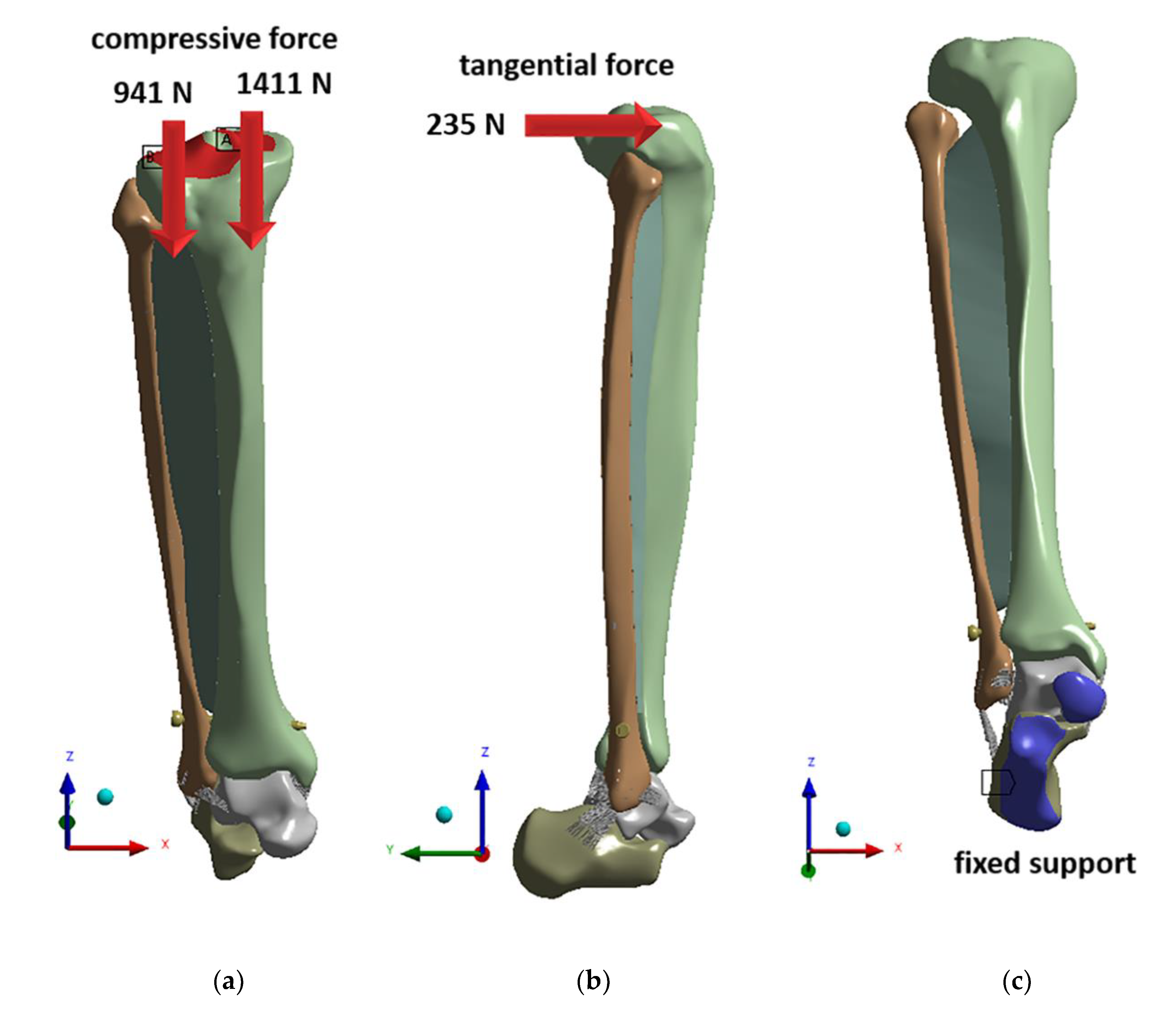
Figure 3.
Loading conditions applied to the finite element (FE) model: (a) compressive force, (b) tangential force, and (c) fixed support.
Figure 3.
Loading conditions applied to the finite element (FE) model: (a) compressive force, (b) tangential force, and (c) fixed support.
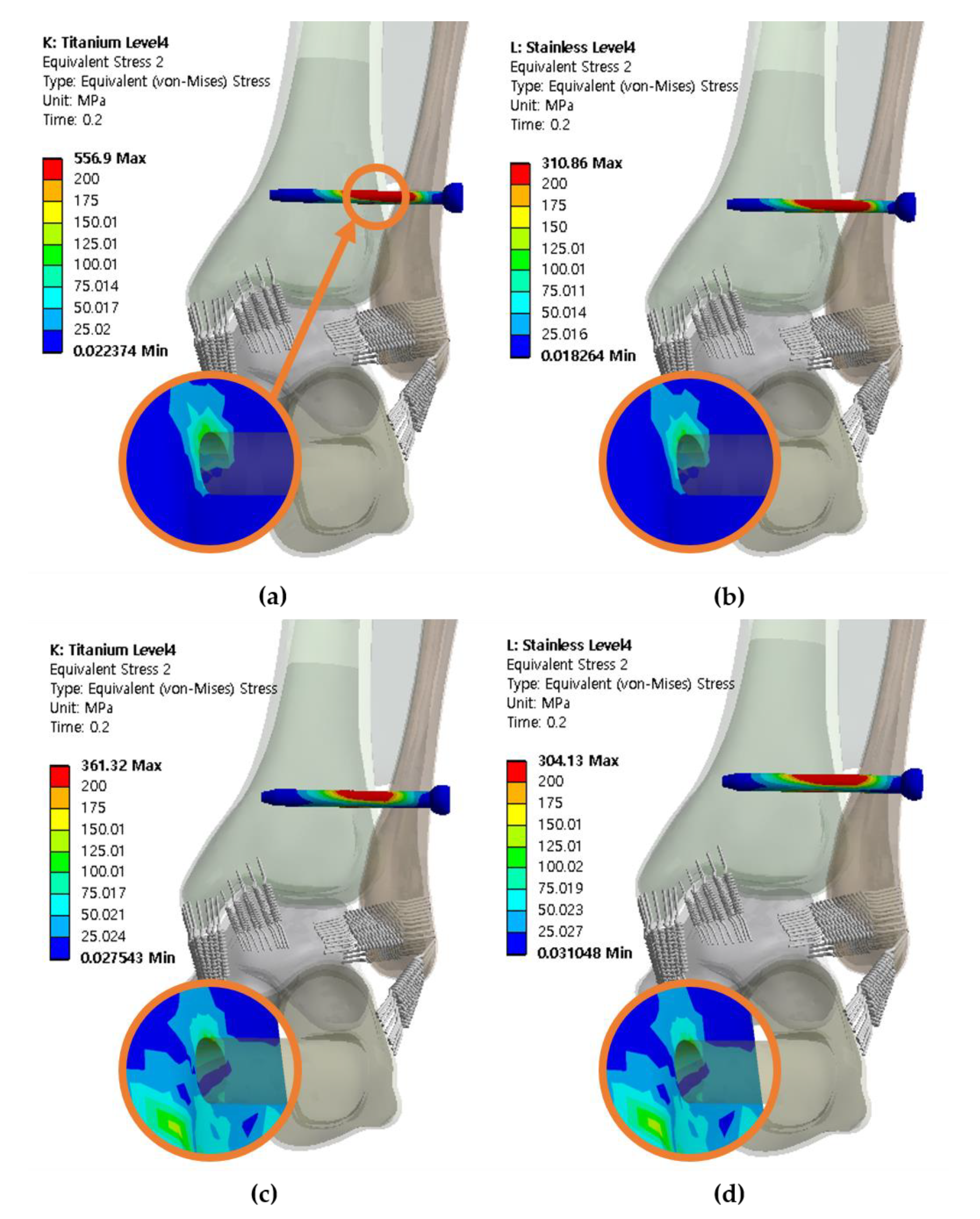
Figure 4.
The von Mises stresses of the syndesmotic screw and adjacent bone at screw level of 25 mm with three cortical bones purchased: (a) titanium screw with a diameter of 3.5 mm, (b) stainless steel screw with a diameter of 3.5 mm, (c) titanium screw with a diameter of 4.5 mm, (d) stainless steel screw with a diameter of 4.5 mm.
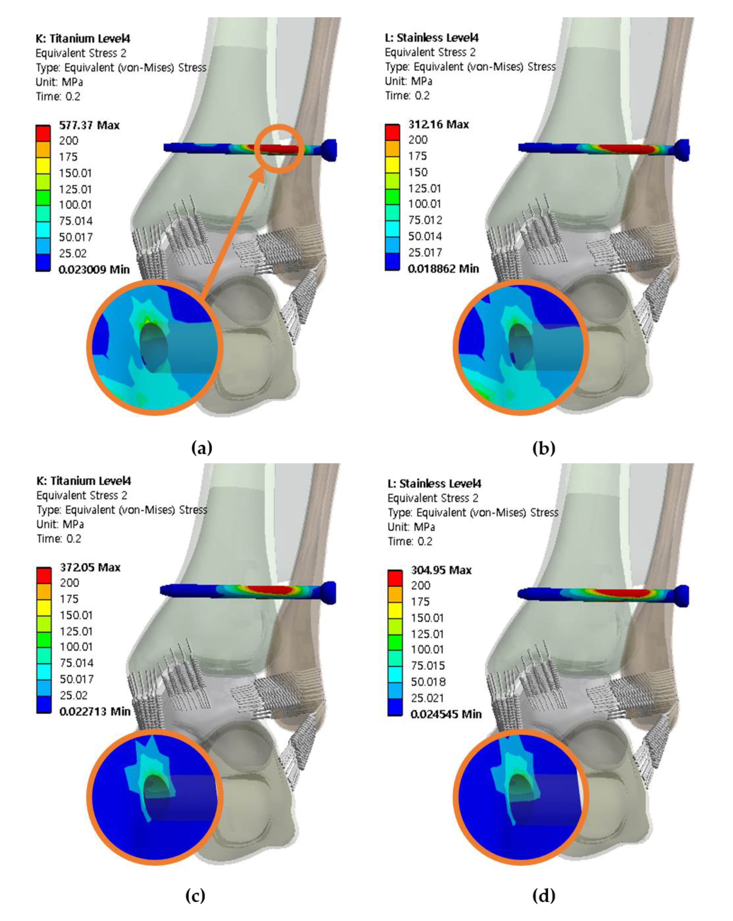
Figure 5.
The von Mises stresses of the syndesmotic screw and adjacent bone at screw level of 25 mm with four cortical bones purchased: (a) titanium screw with a diameter of 3.5 mm, (b) stainless steel with a diameter of 3.5 mm, (c) titanium screw with a diameter of 4.5 mm, and (d) stainless steel screw with a diameter of 4.5 mm.
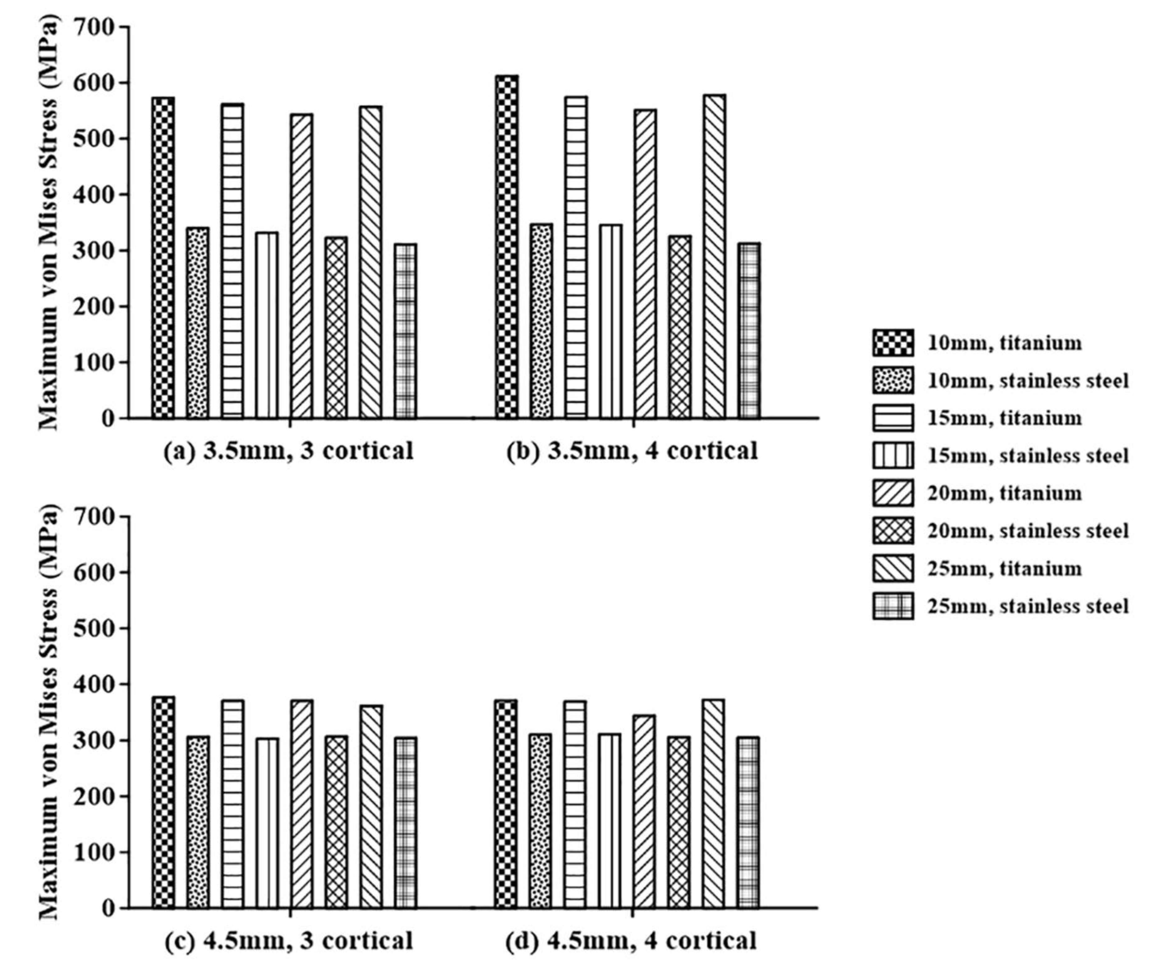
Figure 6.
Analysis of the maximum von Mises stresses of the syndesmotic screw in terms of the syndesmotic screw material for screws with diameters of: (a) 3.5 mm penetrating three cortical bones, (b) 3.5 mm penetrating four cortical bones, (c) 4.5 mm penetrating three cortical bones, and (d) 4.5 mm penetrating four cortical bones.
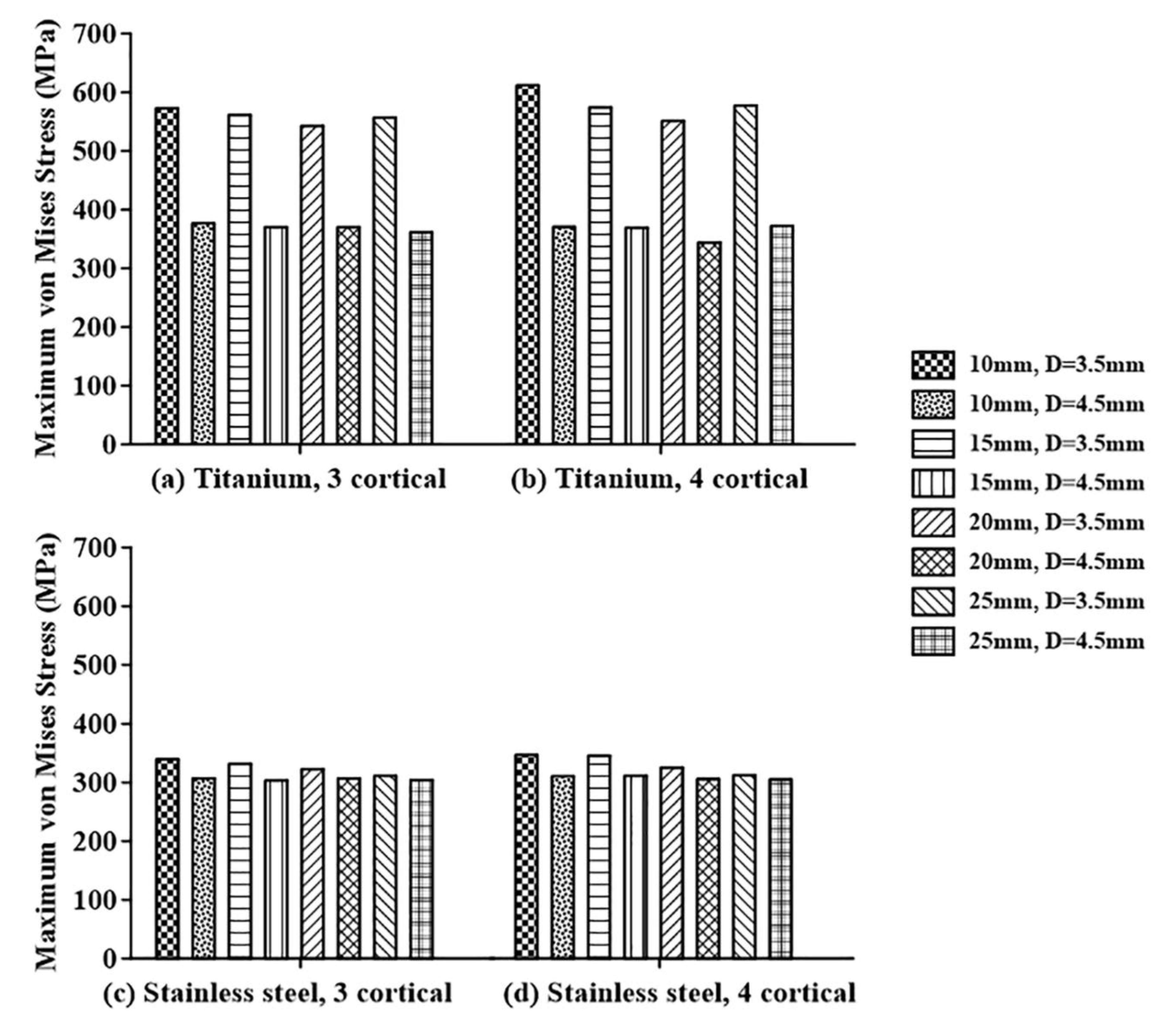
Figure 7.
Analysis of the maximum von Mises stresses of the syndesmotic screw in terms of the diameter of the syndesmotic screw for: (a) titanium screw penetrating three cortical bones, (b) titanium screw penetrating four cortical bones, (c) stainless steel screw penetrating three cortical bones, and (d) stainless steel screw penetrating four cortical bones.
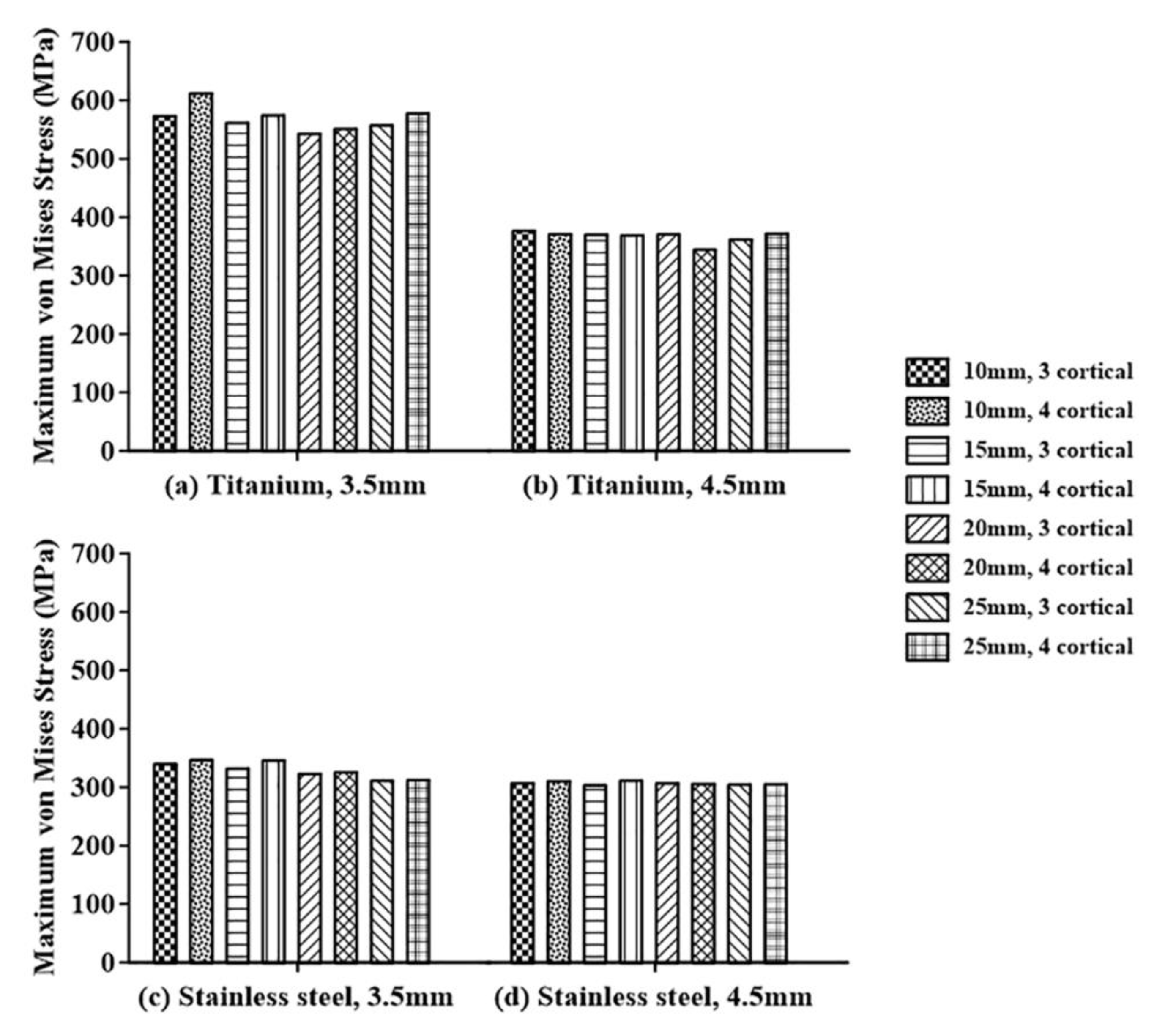
Figure 8.
Analysis of the maximum von Mises stresses of the syndesmotic screw in terms of the number of penetrated cortical bones for: (a) titanium screw with a diameter of 3.5 mm, (b) titanium screw with a diameter of 4.5 mm, (c) stainless steel screw with a diameter of 3.5 mm, and (d) stainless steel screw with a diameter of 4.5 mm.
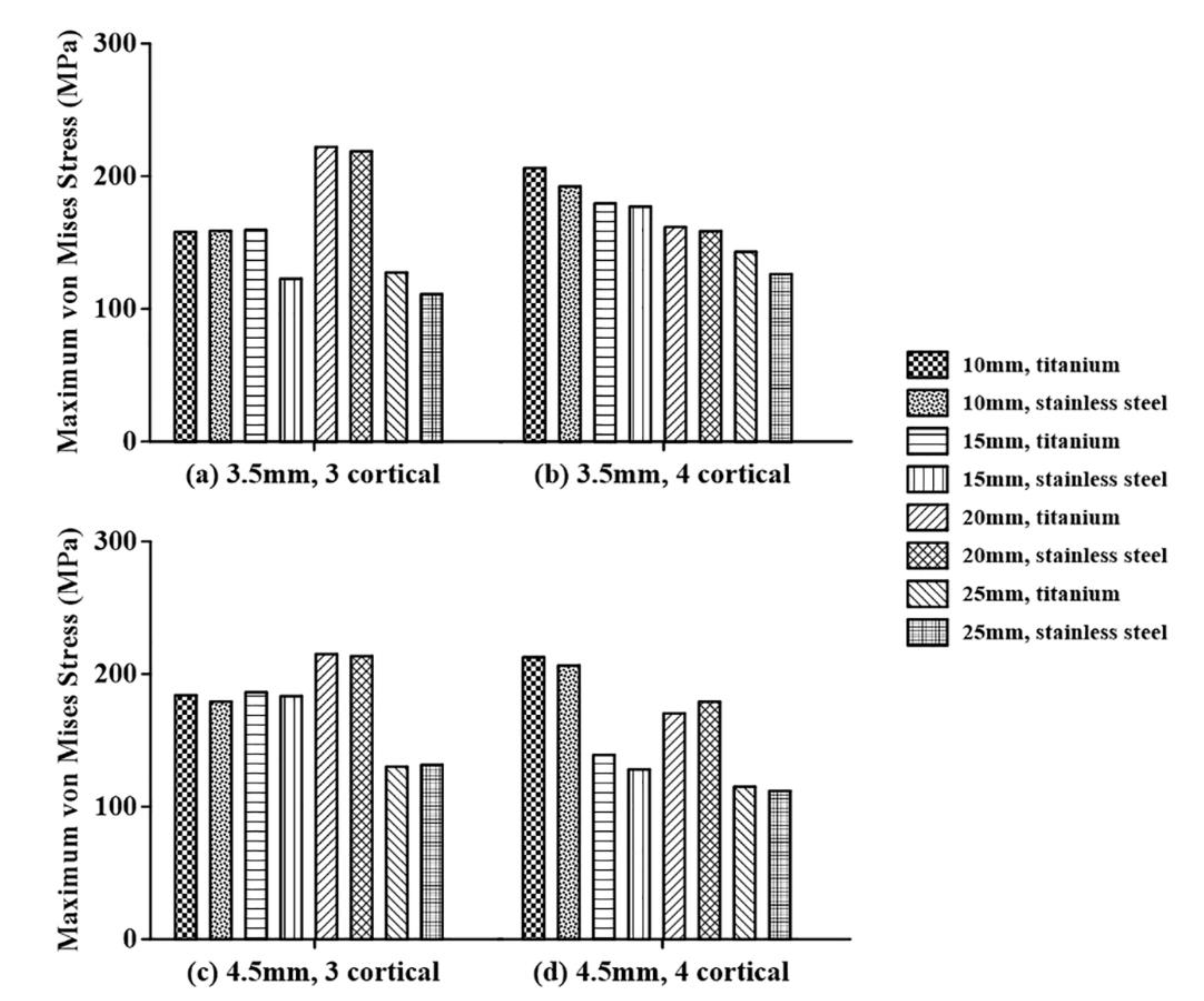
Figure 9.
Analysis of the maximum von Mises stresses of the adjacent bone in terms of the screw material for screws with diameters of: (a) 3.5 mm penetrating three cortical bones, (b) 3.5 mm penetrating four cortical bones, (c) 4.5 mm penetrating three cortical bones, and (d) 4.5 mm penetrating four cortical bones.
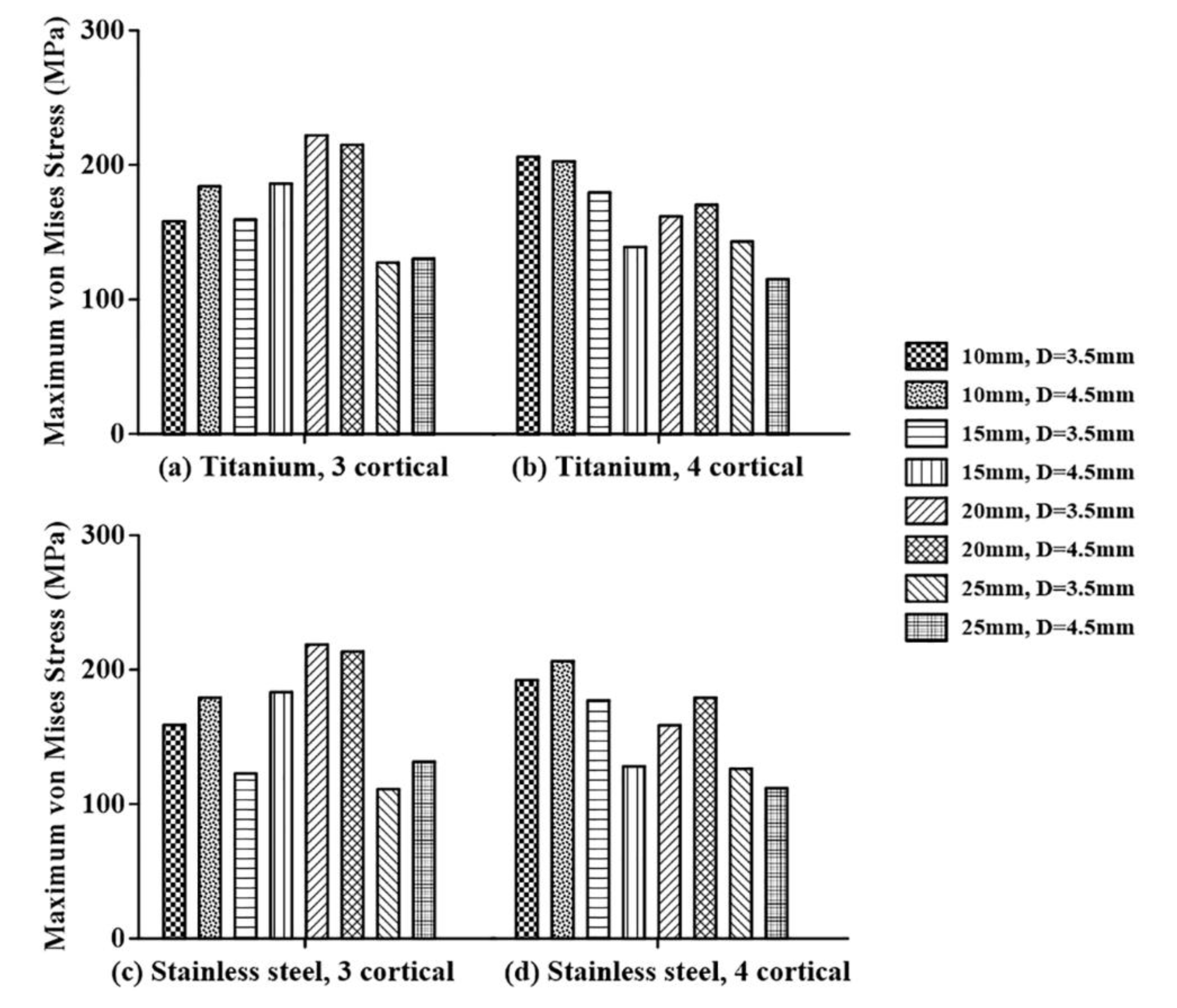
Figure 10.
Analysis of the maximum von Mises stresses of the adjacent bone in terms of the diameter of the screw for: (a) titanium screw penetrating three cortical bones, (b) titanium screw penetrating four cortical bones, (c) stainless steel screw penetrating three cortical bones, and (d) stainless steel screw penetrating four cortical bones.
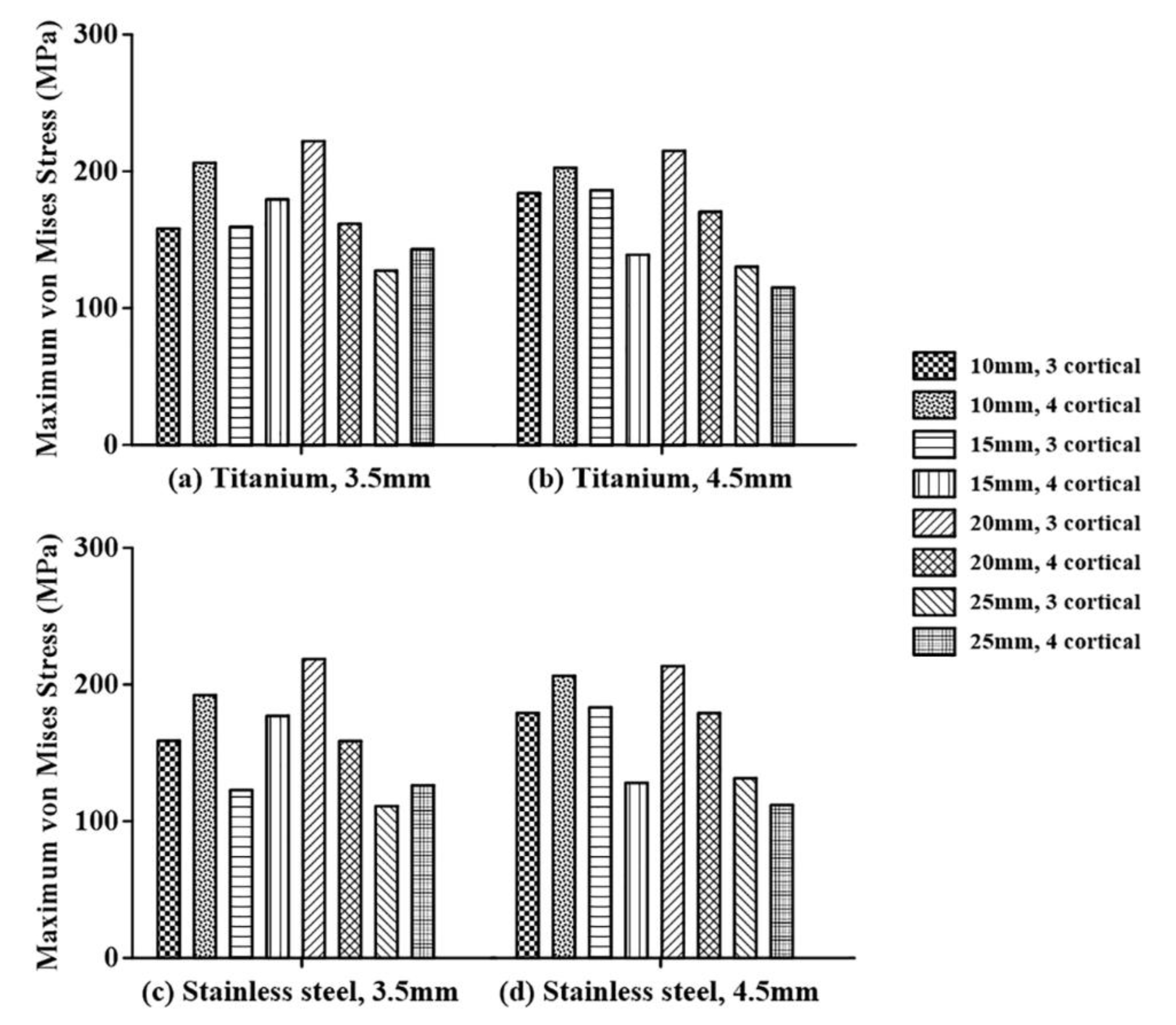
Figure 11.
Analysis of the maximum von Mises stresses of the adjacent bone in terms of the number of penetrated cortical bones for: (a) titanium screw with a diameter of 3.5 mm, (b) titanium screw with a diameter of 4.5 mm, (c) stainless steel screw with a diameter of 3.5 mm, and (d) stainless steel screw with a diameter of 4.5 mm.
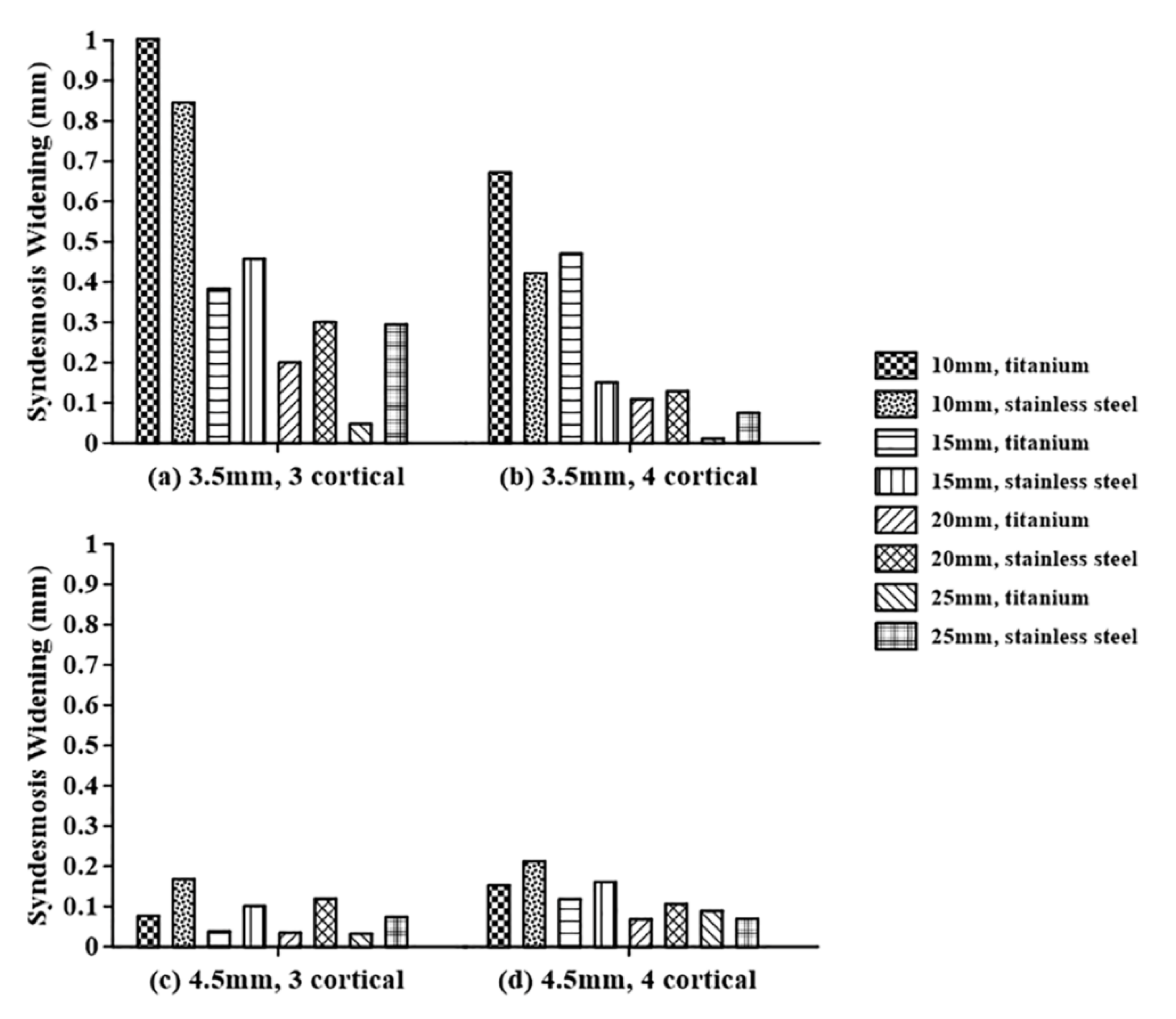
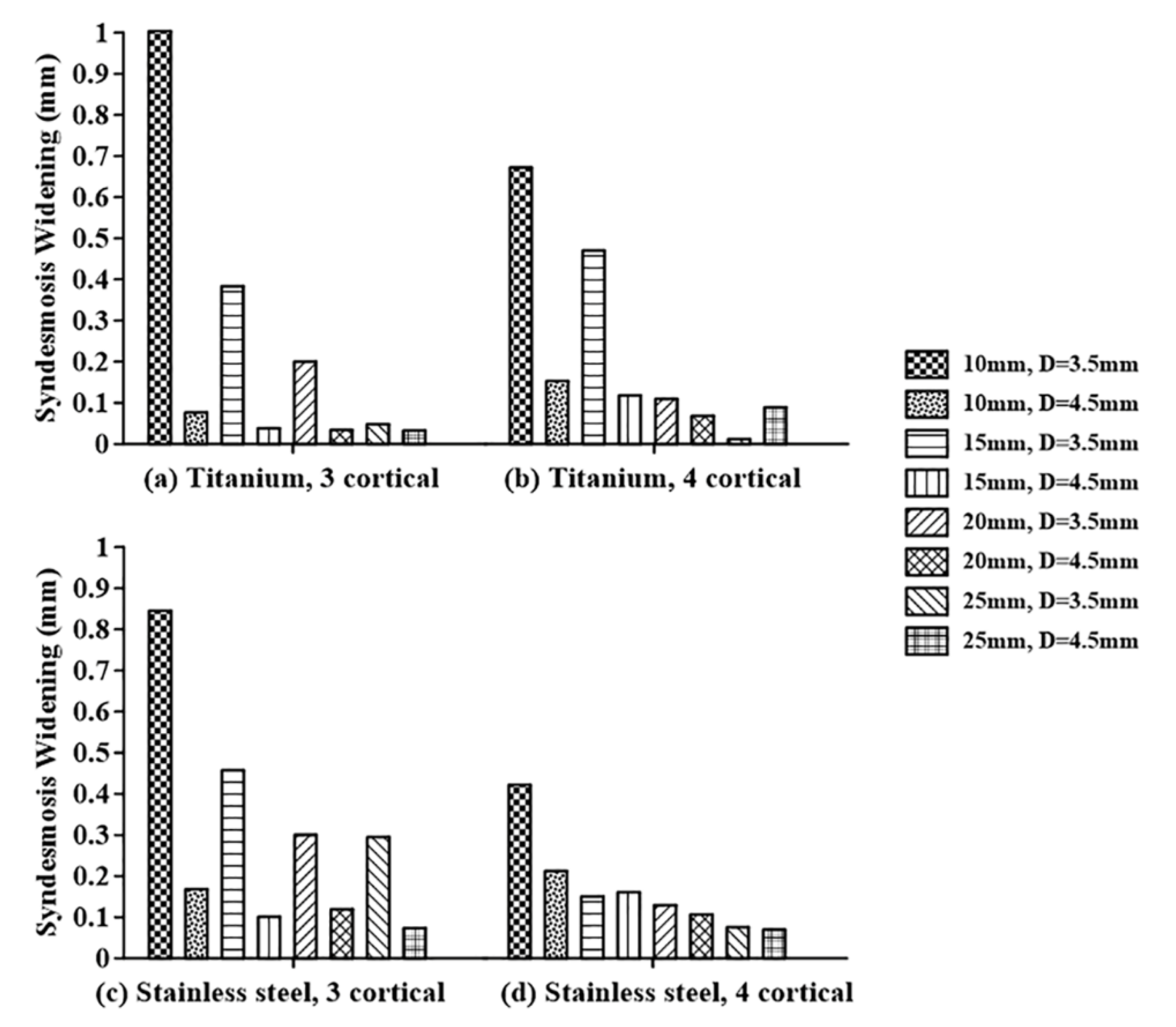
Figure 12.
Analysis of the syndesmosis widening in terms of the screw material for screws with diameters of: (a) 3.5 mm penetrating into three cortical bones, (b) 3.5 mm penetrating into four cortical bones, (c) 4.5 mm penetrating into three cortical bones, and (d) 4.5 mm penetrating into four cortical bones.
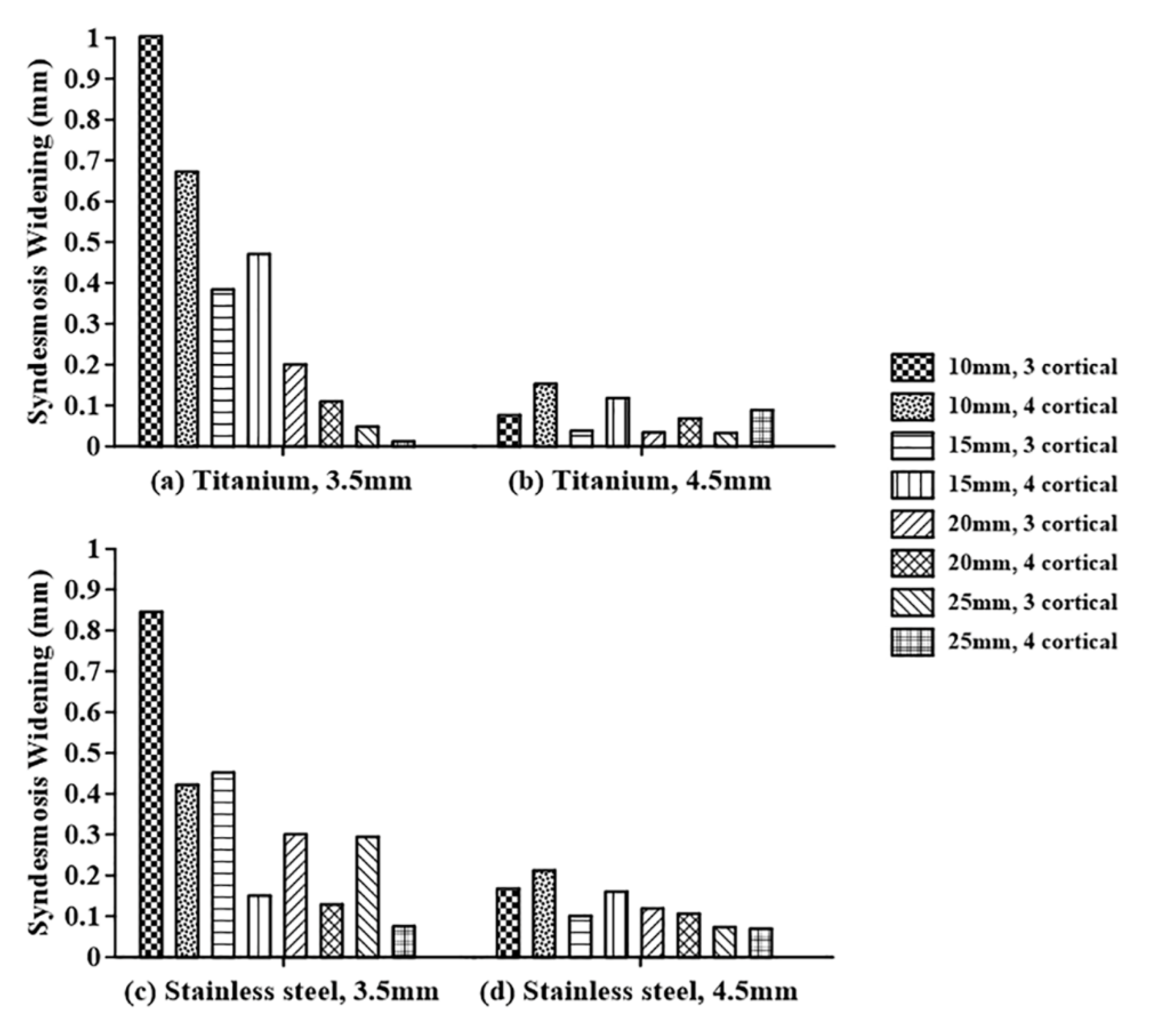
Figure 13.
Analysis of the syndesmosis widening in terms of the screw diameter for: (a) titanium screw penetrating into three cortical bones, (b) titanium screw penetrating into four cortical bones, (c) stainless steel screw penetrating into three cortical bones, and (d) stainless steel screw penetrating into four cortical bones.
Figure 14.
Analysis of the syndesmosis widening in terms of the number of penetrated cortical bones: (a) titanium screw with a diameter of 3.5 mm, (b) titanium screw with a diameter of 4.5 mm, (c) stainless steel screw with a diameter of 3.5 mm, and (d) stainless steel screw with a diameter of 4.5 mm.
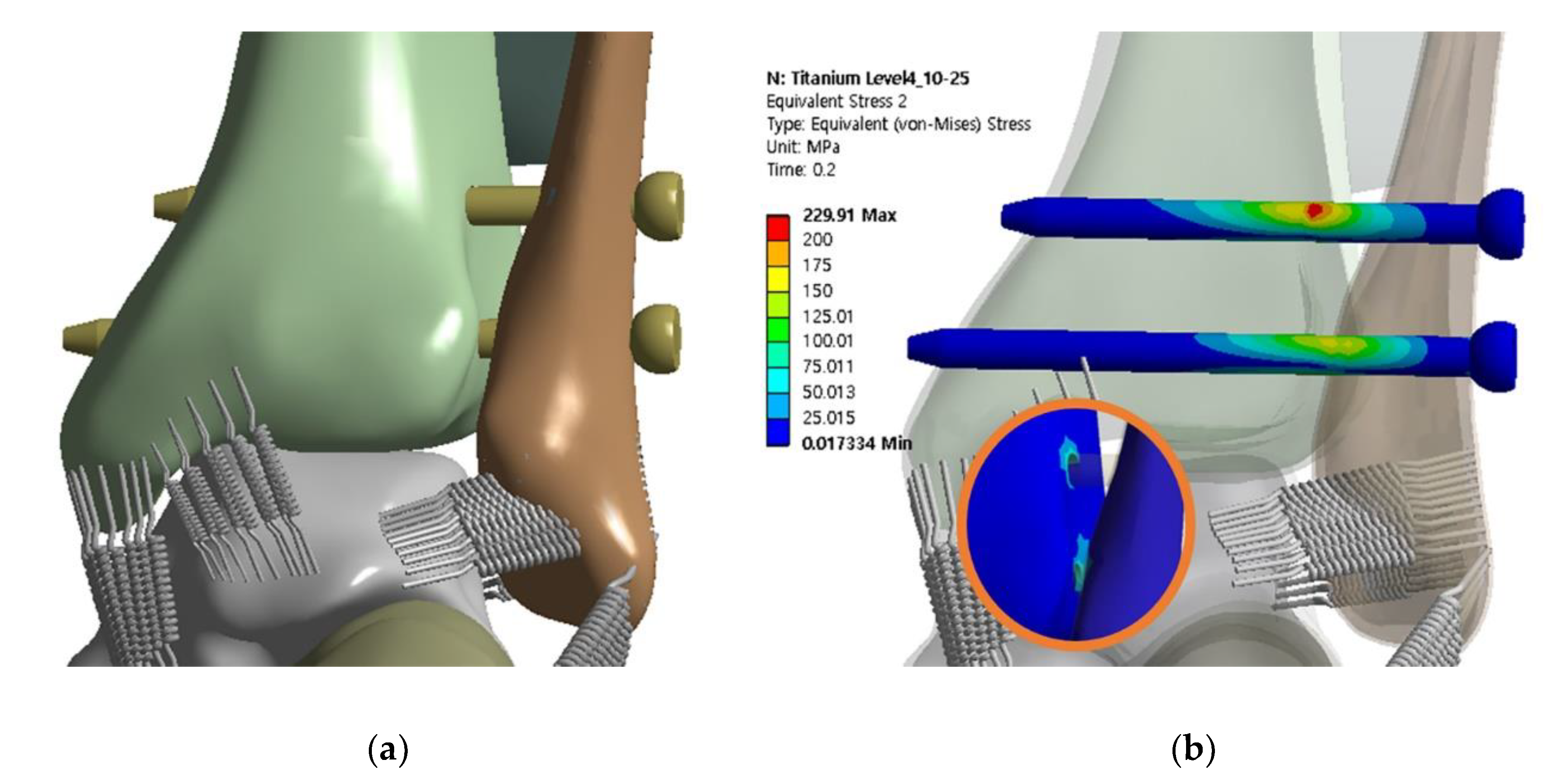
Figure 15.
Finite element model and distribution of maximum equivalent stress with screws inserted at levels of 10 and 25 mm: (a) finite element model of syndesmotic fixation with double screws, and (b) maximum equivalent stresses of the screws and adjacent bone.
Figure 15.
Finite element model and distribution of maximum equivalent stress with screws inserted at levels of 10 and 25 mm: (a) finite element model of syndesmotic fixation with double screws, and (b) maximum equivalent stresses of the screws and adjacent bone.
Table 1.
Specifications of the finite element model.
Table 1.
Specifications of the finite element model.
| Parameter | Value (Unit) |
|---|
| Screw level | 10, 15, 20, and 25 (mm) |
| Diameter of screw | 3.5 and 4.5 (mm) |
| Material of screw | Titanium and stainless steel |
| Number of penetrated cortical bones | 3 and 4 |
Table 2.
Properties of various materials.
Table 2.
Properties of various materials.
| | Young’s Modulus (MPa) | Poisson’s Ratio | Tensile/Compressive Ultimate Strength (MPa) |
|---|
| Cortical bone | 17.000 | 0.3 | 230 |
| Cancellous bone | 700 | 0.2 | 6 |
| Interosseous membrane | 260 | 0.49 | 45 |
| Screw (Titanium: Ti-6Al-4V) | 106.000 | 0.33 | 896 |
| Screw (Stainless steel: 316L) | 193.000 | 0.27 | 584 |
Table 3.
Properties of ankle joint ligaments.
Table 3.
Properties of ankle joint ligaments.
| Ligaments | Stiffness (N/cm) |
|---|
| Anterior talofibular | 399.9 |
| Calcaneofibular | 705.1 |
| Posterior talofibular | 397.5 |
| Deep deltoid | 1288.2 |
Table 4.
Analysis of state and influence on interpretation by mesh densities.
Table 4.
Analysis of state and influence on interpretation by mesh densities.
| | Coarse | Medium | Fine |
|---|
| Number of elements | 51.657 | 80.918 | 271.882 |
| Number of nodes | 92.875 | 149.613 | 498.461 |
| Approximate computational time (min) | 100 | 120 | 1400 |
| Stress on the screw (MPa) | 320.24 | 344.13 | 346.22 |
| Syndesmosis widening (mm) | 0.0587 | 0.0682 | 0.0715 |
Table 5.
Maximum von Mises stresses and syndesmosis widening: titanium screw with three cortical bones purchased.
Table 5.
Maximum von Mises stresses and syndesmosis widening: titanium screw with three cortical bones purchased.
| Diameter (mm) | Level (mm) | Maximum von Mises Stress (MPa) | Syndesmosis Widening (mm) |
|---|
| Screw | Adjacent Bone |
|---|
| 3.5 | 10 | 572.85 | 158.04 | 1.0036 |
| 3.5 | 15 | 561.33 | 159.34 | 0.3838 |
| 3.5 | 20 | 542.85 | 222.02 | 0.2003 |
| 3.5 | 25 | 556.90 | 127.28 | 0.0479 |
| 4.5 | 10 | 376.49 | 183.99 | 0.0764 |
| 4.5 | 15 | 370.14 | 186.13 | 0.0380 |
| 4.5 | 20 | 370.28 | 214.93 | 0.0342 |
| 4.5 | 25 | 361.32 | 130.21 | 0.0327 |
Table 6.
Maximum von Mises stresses and syndesmosis widening: titanium with four cortical bones purchased.
Table 6.
Maximum von Mises stresses and syndesmosis widening: titanium with four cortical bones purchased.
| Diameter (mm) | Level (mm) | Maximum von Mises Stress (MPa) | Syndesmosis Widening (mm) |
|---|
| Screw | Adjacent Bone |
|---|
| 3.5 | 10 | 611.60 | 206.07 | 0.6722 |
| 3.5 | 15 | 574.21 | 179.42 | 0.4707 |
| 3.5 | 20 | 550.93 | 161.62 | 0.1095 |
| 3.5 | 25 | 577.37 | 142.97 | 0.0117 |
| 4.5 | 10 | 370.49 | 202.59 | 0.1526 |
| 4.5 | 15 | 368.86 | 139.03 | 0.1179 |
| 4.5 | 20 | 344.13 | 170.35 | 0.0682 |
| 4.5 | 25 | 372.05 | 115.01 | 0.0891 |
Table 7.
Maximum von Mises stresses and syndesmosis widening: stainless steel screw with three cortical bones purchased.
Table 7.
Maximum von Mises stresses and syndesmosis widening: stainless steel screw with three cortical bones purchased.
| Diameter (mm) | Level (mm) | Maximum von Mises Stress (MPa) | Syndesmosis Widening (mm) |
|---|
| Screw | Adjacent Bone |
|---|
| 3.5 | 10 | 339.51 | 158.80 | 0.8457 |
| 3.5 | 15 | 331.52 | 122.77 | 0.4571 |
| 3.5 | 20 | 322.58 | 218.66 | 0.3005 |
| 3.5 | 25 | 310.86 | 111.07 | 0.2947 |
| 4.5 | 10 | 306.51 | 179.14 | 0.1680 |
| 4.5 | 15 | 303.12 | 183.27 | 0.1008 |
| 4.5 | 20 | 306.65 | 213.48 | 0.1193 |
| 4.5 | 25 | 304.13 | 131.49 | 0.0738 |
Table 8.
Maximum von Mises stresses and syndesmosis widening: stainless steel screw with four cortical bones purchased.
Table 8.
Maximum von Mises stresses and syndesmosis widening: stainless steel screw with four cortical bones purchased.
| Diameter (mm) | Level (mm) | Maximum von Mises Stress (MPa) | Syndesmosis Widening (mm) |
|---|
| Screw | Adjacent Bone |
|---|
| 3.5 | 10 | 346.58 | 192.24 | 0.4217 |
| 3.5 | 15 | 345.39 | 177.06 | 0.1504 |
| 3.5 | 20 | 325.30 | 158.60 | 0.1292 |
| 3.5 | 25 | 312.16 | 126.25 | 0.0752 |
| 4.5 | 10 | 310.08 | 206.35 | 0.2123 |
| 4.5 | 15 | 310.96 | 128.06 | 0.1608 |
| 4.5 | 20 | 305.58 | 179.07 | 0.1062 |
| 4.5 | 25 | 304.95 | 111.87 | 0.0696 |
Table 9.
Maximum von Mises stresses and syndesmosis widening: double titanium screw of 4.5 diameter with four cortical bones.
Table 9.
Maximum von Mises stresses and syndesmosis widening: double titanium screw of 4.5 diameter with four cortical bones.
| Level (mm) | Maximum von Mises Stress (MPa) | Syndesmosis Widening (mm) |
|---|
| Screw | Adjacent Bone |
|---|
| 25 | 372.05 | 115.01 | 0.0891 |
| 15 and 25 | 261.96 | 103.66 | 0.1008 |
| 10 and 25 | 229.91 | 98.30 | 0.0786 |


