Article

Novel Online Optimized Control for Underwater Pipe-Cleaning Robots

1
The State Key Laboratory of Fluid Power and Mechatronic systems, Zhejiang University, Hangzhou 310027, China
2
Ningbo Research Institute, Zhejiang University, Hangzhou 315000, China
*
Author to whom correspondence should be addressed.
Appl. Sci. 2020, 10(12), 4279; https://doi.org/10.3390/app10124279
Submission received: 21 May 2020 / Revised: 11 June 2020 / Accepted: 17 June 2020 / Published: 22 June 2020
(This article belongs to the Section Marine Science and Engineering)

Abstract

:
Due to the particularity of the jacket structure of offshore platforms and the complexity of the marine environment, there have been few effective localization and autonomous control methods for underwater robots that are designed for cleaning tasks. To improve this situation, a fusion bat algorithm (BA) online optimized fuzzy control method using vision localization was developed based on the constraints of the underwater operational environment. Vision localization was achieved based on images from a catadioptric panoramic imaging system. The features of the pipe edge and the boundary of the area covered by biofouling were obtained by image processing and feature extraction. The feature point chosen as the “highest” point of the boundary was calculated by projection transformation to generate the reference path. The specialized fuzzy controller was designed to drive the robot to track the reference path, and an improved bat algorithm with dynamic inertia weight and differential evolution method was developed to optimize the scale factors of the fuzzy controller online. The control method was simulated and further implemented on an underwater pipe-cleaning robot (UPCR), and the results indicate its rationality and validity.

1. Introduction

Offshore platforms play an important role in marine resource exploitation, and jackets made of steel pipes are essential structural supports for oil rigs. As barnacles, algae, and other forms of marine life always adhere to their surface, these pipes need periodical cleaning to prevent load increase and corrosion [1,2]. Until now, most of these cleaning tasks have been accomplished manually, which is of low efficiency and high cost, and presenting potential safety threats to the divers. Therefore, it is essential to replace manual labor by underwater robots.
In recent years, climbing robots have been developed for industrial applications, especially in the area of cleaning underwater structures [3,4]. These robots utilize propulsion force adhesion [5,6,7,8], magnetic force adhesion [9,10], and clamping [11] to achieve stable locomotion and withstand the counterforce brought on by cleaning operations. All of them, however, focused only on locomotion, adaptation, or the cleaning method, which are the basic functions of climbing robots used for cleaning. As these underwater robots may work several to over twenty hours a day and operators can only concentrate effectively for 30–60 min before their driving ability declines [12], automation is urgently required not only to relieve the stress of operators but also to improve the operational efficiency.
Many researches have paid attention to localization, navigation, and motion control of climbing robots to achieve automation [13]. MagneBike, also moving on the pipe, uses a localization strategy based on 3D scan registration and 3D odometry, and transforms the path from 3D space into 2D space by projecting movements into local surface planes, allowing for 2D trajectory tracking [14,15]. In addition, multiple methods and devices have been utilized to achieve stable motion and autonomous control of climbing robots, including computer vision [12,16,17] or structural light-based computer vision [18,19,20], 3D perception sources [21], dead reckoning [22], and external guidance [23]. As the methods above were commonly developed considering the constraints of a particular working environment, their performance may decrease if applied to other fields, especially under water. Meanwhile, there have been few effective localization and control methods for underwater cleaning robots due to the complexity of the marine environment.
3D localization is an indispensable step towards the implementation of a semiautonomous or autonomous control. However, according to underwater environment specifications [9], an accurate global localization is either hard to achieve or inadequate for cleaning tasks. Thus, we propose a compromised method composed of rough global localization and accurate local localization, which, respectively, helps operators locate approximately the underwater pipe-cleaning robot (UPCR) and provides reference paths and movement errors for the control method.
The global localization of a UPCR was demonstrated in our previous work [24]. Based on the transfer matrix between the global coordinate and the UPCR coordinate, the orientation error between the axis of the pipe and the UPCR, accelerometer measurements, and the inclination of the pipe were fused to calculate the relative orientation between the pipe and the UPCR. Then, combined with the liquid level transmitter, the global localization of the UPCR was obtained.
This paper focuses on the local localization and autonomous control of the UPCR. As the boundary of the area covered by biofouling is always irregular, the “highest” point on the boundary along the direction of the pipe’s axis was chosen as the feature point, and the line on the pipe across the point that was vertical to the axis of the pipe was defined as the reference path, as shown in Figure 1. During local localization, therefore, the pipe edge and the biofouling boundary in the image are first recognized. The orientation error of the UPCR is calculated based on the inclination of the pipe’s edge. Then, according to the position of the boundary and projection transformation rules, the coordinates of the real boundary in the base coordinate are obtained. Finally, the feature point and the reference path are determined to calculate the movement errors of the UPCR. These movement errors are inputs for the designed fuzzy controller, which turns the UPCR toward the reference path. A fusion bat algorithm (BA) with dynamic inertia factor and differential evolution method is also used to improve the performance of the fuzzy controller.
This paper is organized as follows. Section 2 provides a concise introduction of the UPCR prototype and its operational mode, and the local localization method based on a catadioptric panoramic image. Section 3 describes a novel fuzzy controller optimized by the fusion bat algorithm. Section 4 and Section 5 verify the proposed controller by simulation and experiment, respectively. Finally, conclusions are given in Section 6.

2. Catadioptric Panoramic Image-Based Vision Localization

2.1. Prototype Description

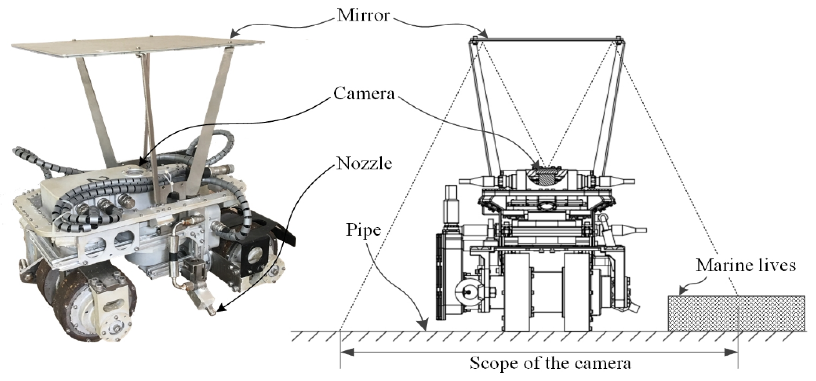
A UPCR is a wheeled climbing robot designed to clean biofouling covered on the jacket of offshore platforms. Equipped with magnetic wheels and a self-adaption mechanism, a UPCR can move steadily on the pipe, while stripping the biofouling with a cavitation water jet [9,25]. In order to observe the UPCR’s surrounding environment during operation, a catadioptric panoramic imaging system composed of a camera and a mirror was designed to acquire images for local localization, as shown in Figure 2. The camera was upward integrated in the body of the UPCR and obtained the panoramic image of the robot from the mirror. An Aviterich D5I22 webcam module (Shenzhen ARTON Tech. Cor., Ltd., Guangdong, China) with 1920 × 1080 pixel resolution and frame rate of 20 fps was chosen due to its compact size (38 × 38 × 45 mm3), light weight (0.08 kg), and low price (75 dollars). Based on this panoramic image, feature extraction and projection transformation were successively operated. Then, the reference path was generated and errors between the UPCR and reference path were calculated.
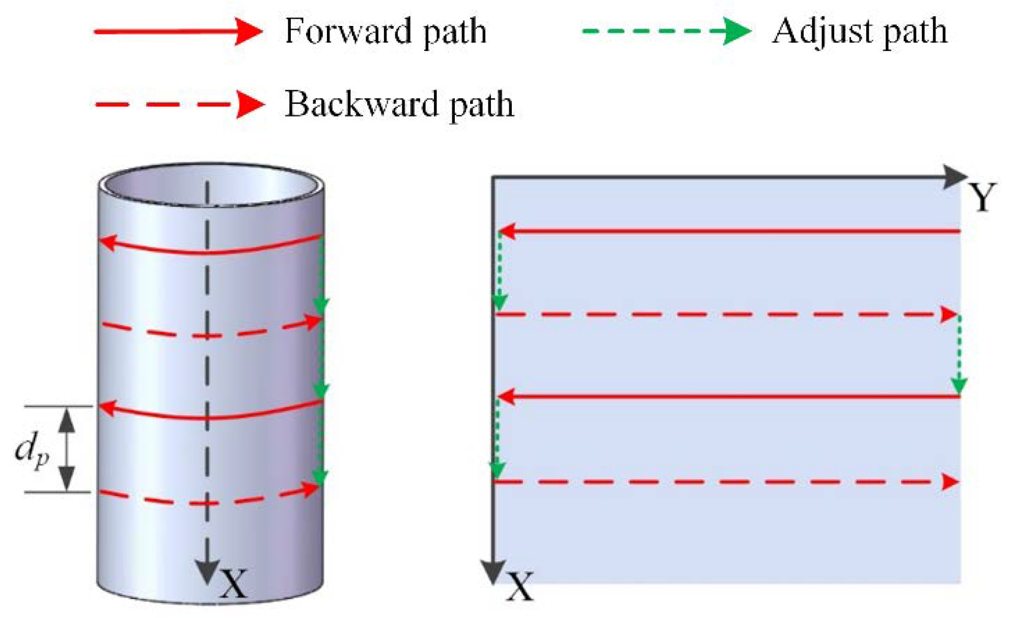
It is worth noting that the UPCR moves circumferentially and downward gradually to ensure that all the biofouling in its path is cleaned up; therefore, the highest point of the biofouling is chosen as the reference, as described in Section 1. Meanwhile, in order to avoid cable tangling around the pipe, the robot moves backward and forward circumferentially. Since the diameter of each pipe is uniform, the motion of the UPCR on the pipe can be equivalent to the motion on a rectangular plane. The operational trajectory of UPCR is shown in Figure 3.

2.2. Feature Extraction

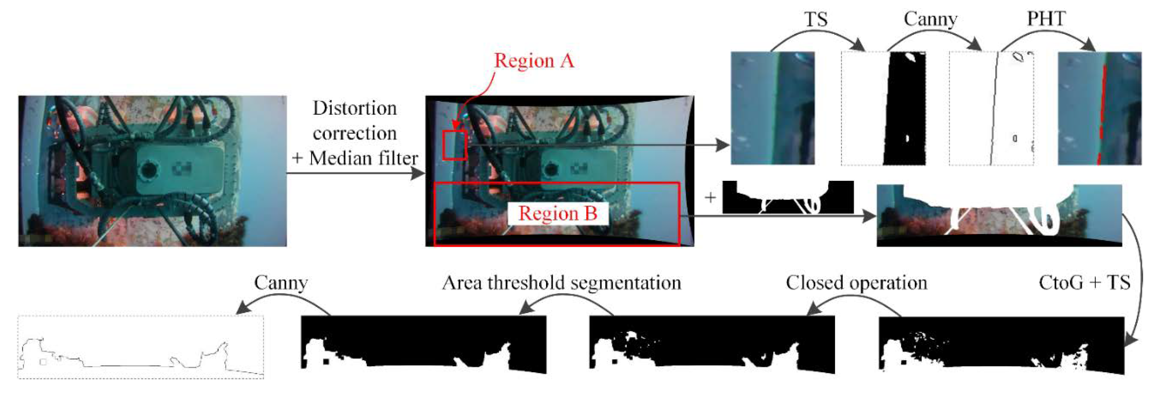
The process of the method used to obtain the features of the pipe edge and the biofouling boundary in the field is shown in Figure 4. Equipped with a wide-angle lens, the camera produces images with barrel distortion, which is first corrected based on the internal and external parameters of the camera. Median filter, a nonlinear filtering method, is simultaneously applied as it can overcome the blurriness generated by the linear filtering method while maintaining and enhancing the edge details [26]. Then, two regions of interest, namely the edge of the pipe and the boundary of the biofouling, are chosen to reduce unnecessary calculation.
With respect to Region A, threshold segmentation (TS) and an edge recognition method with canny operator were applied to extract the pipe edge [27]. Considering that the edge may not be a straight line as the pipe is not smooth, a probabilistic Hough transform (PHT) was performed to generate lines from the pipe edge, which can be formulated as follows:
y = k i x + b i    i = 1 , 2 , , n
Thus, the feature line of the pipe edge can be computed using Equation (2).
y = k i n x + b i n    i = 1 , 2 , , n
As for Region B, it was first overlaid by a preprocessed image to eliminate the disturbance of the robot body. Since the relative position of the robot body and the panoramic image system is constant, the preprocessed image is suitable for any situation. Second, the color-to-grey method (CtoG) and threshold segmentation (TS) were used to obtain a binary image. Third, a closed operation, combining dilation and erosion, was then applied to fill the holes that were originally occupied with the biofouling and connect with each other. Fourth, area threshold segmentation was performed to remove the small blobs that were recognized as noise. Finally, an edge recognition method with canny operator was used to extract the boundary of the area covered by biofouling.

2.3. Projection Transformation Rules

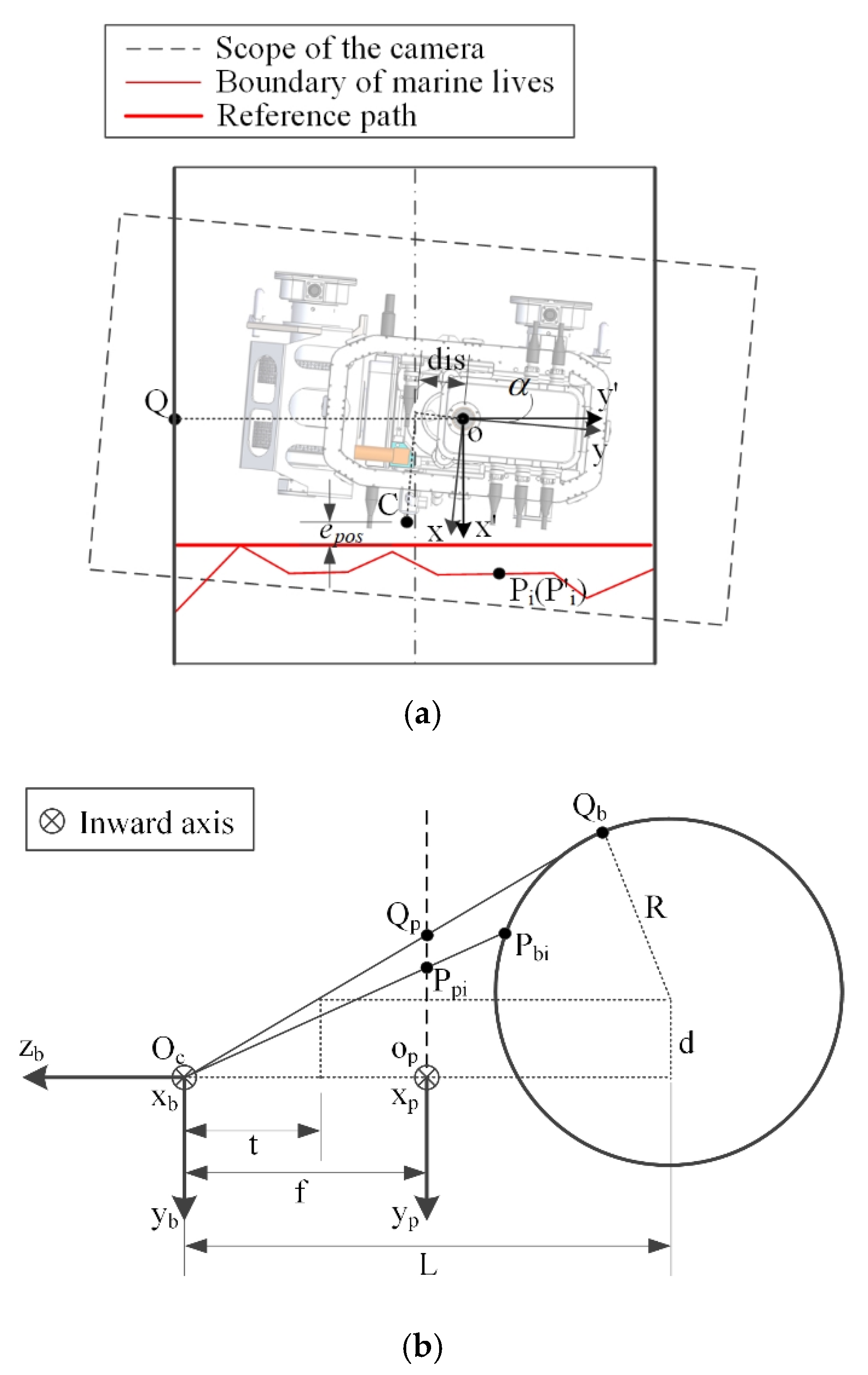
The purpose of projection transformation is to obtain the real position of the biofouling boundary based on the image features. Considering that the UPCR is in a random orientation, two-pixel coordinate systems named xoy and x’oy’ were defined in the captured image, as shown in Figure 5a. Their origin coincided with the optical center of the camera. Axis oy and axis ox’ are parallel to the moving direction of the UPCR and the axis of the pipe, respectively. α is the rotation angle from xoy to x’oy’, and can be calculated based on Equation (3) as follows:
α = arctan n k i    i = 1 , 2 , , n
According to the feature of Region B, points at the boundary of the area covered by biofouling can be described as Pi(xi,yi) in xoy. Their coordinates change to P’i(xi’,yi’) in x’oy’, which can be calculated by Equation (4):
{ x i = x i cos ( α ) y i sin ( α ) y i = x i sin ( α ) + y i cos ( α )
The camera imaging model is presented in Figure 5b. Ocxbybzb is the base coordinate system and xpopyp is the image coordinate system on the image plane. Oc is the equivalent optical center, which is symmetric with the optical center of the camera about the mirror. Ocxb, opxp, and ox’ (in Figure 5a) have the same direction, as well as Ocyb, opyp, and oy’. Then, Ppi(xpi,ypi) in xpopyp corresponding to P’i(xi’,yi’) is given as follows:
{ x p i = K · x i y p i = K · y i
where K is the scaling factor of coordinate transformation between x’oy’ and xpopyp. It is constant and can be measured in advance by the following method.
One of the points at the pipe edge is first chosen as Q(0,yQ’) in x’oy’ (Figure 5a), and Qb is the corresponding point of Q on the pipe (Figure 5b). Thus, OcQb and the pipe are tangent. Then, the corresponding point of Q in xpopyp defined Qp(0,yQp) can be calculated as follows:
y Q p = f t · d
where f is the focal length and d is the distance between Oc and the pipe along axis Ocyb, which is given as follows:
d = d i s cos α
where dis is the distance between the camera and the center of the UPCR, as shown in Figure 5a. t is a temp parameter that can be calculated based on geometric similarity as follows:
t 2 + d 2 L t = d R
where R is the radius of the pipe and L is the distance between Oc and the pipe along axis Oczb. Thus, K is given as Equation (9):
K = y Q p y Q
As equations of the line OcPbi and the surface of the pipe can be defined as Equations (10) and (11), respectively, the coordinates of points at the boundary of the area covered by biofouling on the pipe named Pbi(xbi,ybi,zbi) can be calculated based on Equations (4), (5), (10), and (11):
x b i x p i = y b i y p i = z b i f
( z b i + L ) 2 + ( y b i + d ) 2 = R 2

2.4. Deviation Calculation

The point that has the smallest xbi is chosen as the feature point according to Figure 1. Then, the reference path can be defined as follows and as shown in Figure 5a:
{ ( z b + L ) 2 + ( y b + d ) 2 = R 2 x = x b min
where xbmin is equal to the minimum value of xbi.
Considering that the purpose of the robot is to clean the pipe, it is better to have the cleaning equipment follow the reference path. As the coordinate of the cleaning equipment is C(xcr, ycr) in the robot coordinate system xroyr with oyr towards the front of the UPCR and oxr towards the right of the UPCR, the orientation error eori and the position error epos of the UPCR can be given as Equation (13):
e o r i = α e p o s = x b min ( x c r cos α y c r sin α )

3. Fusion Bat Algorithm-Optimized Fuzzy Controller

The UPCR has three actuators situated in the front wheel, the back wheel, and the turning mechanism. Based on the kinematic model of the robot [25], the number of active degrees of freedom (DOFs) is two as movement of the back wheel is constrained by the front wheel and the turning mechanism. Meanwhile, because the velocity of the front wheel is always slow and does not affect the trajectory to follow the reference path, it is preset and the angle of the turning mechanism is determined as the control output.
The application of the UPCR has two major characteristics—on the one hand, the boundary of sea creatures is not a smooth curve and is often in a stepped shape, which makes the reference line discrete and unpredictable; on the other hand, the surface of the steel structure is rugged due to the presence of residual sea creatures and welding seams, causing the UPCR to bump over them, which in turn leads to dramatic shaking in the panoramic image. Thus, the fuzzy controller was chosen as it is less complex in its implementation and inherently robust to noise and parameter uncertainties [28,29], and a fusion bat algorithm was applied to optimize the performance of the fuzzy controller. The diagram of the control flow is shown in Figure 6.

3.1. Fuzzy Controller Design

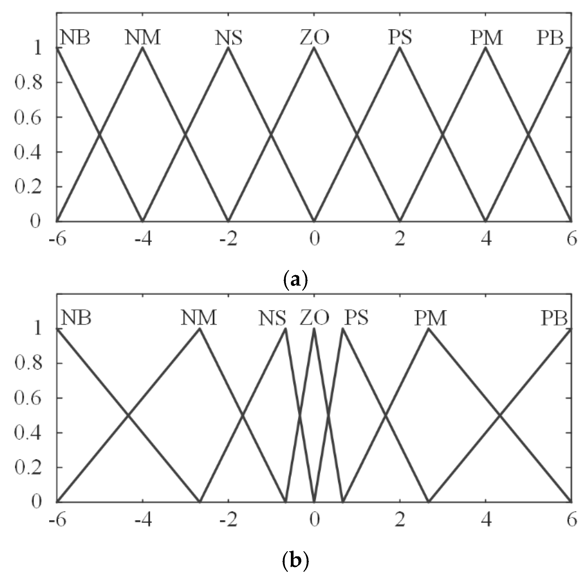
The inputs of the fuzzy controller were chosen as epos and eori, while the output was chosen as the turning angle αt. Their domains of discourse were all [–6, 6], and the fuzzy sets selected for them were named Negative-Big (NB), Negative-Medium (NM), Negative-Small (NS), Zero (ZE), Positive-Small (PS), Positive-Medium (PM), and Positive-Big (PB). The membership functions for the selected fuzzy sets are shown in Figure 7.
Triangular membership functions were adopted as they are the piecewise linear functions proven to be efficient due to their computational simplicity [30]. The fuzzy rules for path tracking were generated by the experiences of manual control, as shown in Table 1. The max-min inference method and the Mamdani method were used in the process of fuzzy inference, and a centroid defuzzifier was applied to obtain the actual turning angle, which was constrained in the range of [−25°, 25°].

3.2. Bat Algorithm Optimization

In order to ensure the fuzzy controller’s good performance, scale factors of the inputs and the output must be properly determined. However, fixed scale factors are not suitable for different deviations, and therefore an online optimization method is required. Many algorithms can be used to optimize parameters, such as the simplex method, a genetic algorithm (GA), the simulated annealing method (SAM), particle swarm optimization (PSO), a bat algorithm (BA), etc. Considering that online optimization requires the high efficiency of the optimization algorithm, BA was selected to optimize the scale factors.
A BA is a nature-inspired algorithm developed by Yang in 2012, which was formulated based on the behavior of bats finding their prey [31]. In this algorithm, each “bat” represents one solution of the optimization problem, which is a set of the three scale factors (i.e., Kpos, Kori, and Kt) in this paper. A certain number of bats are applied to constitute a swarm moving around the search space and searching for the best solution. In order to evaluate the quality of solutions, a fitness function is required. In this paper, integral time absolute error (ITAE) was used, and the fitness function based on epos and eori is formulated as follows:
W = ω 1 0 5 | e p o s | t d t + ω 2 0 5 | e o r i | t d t
where ω1 and ω2 are weight coefficients. As biofouling can be stripped from the pipe only when the cleaning equipment arrives, it is better to eliminate the position error as a priority. Therefore, ω1 and ω2 are set as 0.7 and 0.3, respectively.
A BA provides a quick convergence by switching between exploration and exploitation, but it may lead to stagnation or premature convergence if it switches to exploitation too early [32]. Even though BA parameters have been properly optimized according to published research [33], stagnation and premature convergence still occur in our application.
As the velocity update rule in the BA mainly influences its convergence speed, the dynamic inertia weight is used to solve the stagnation problem. The velocity update rule is changed as follows:
v i t = ω i t v i t 1 + ( x i t x * ) f i
where v, x, f, and ω denote velocity, location, velocity adjusting frequency, and the newly introduced dynamic inertia weight, respectively, while i, t, and t-1 denote bat i, time step t, and its previous time step, respectively. x* denotes the optimal location in the current iteration. Considering that most bats can find better locations during exploration, the dynamic inertia weight need not decrease a lot. When most bats cannot find better locations, exploitation starts and a small dynamic inertia weight can lead to fast convergence. Thus, a success rate of finding better locations is defined to automatically adjust the dynamic inertia weight, which is formulated in Equations (16)–(18):
ω i t = ω min + ( ω max ω min ) P s t
P s t = i = 1 N S i t N
S i t = { 1     i f ( W i t < W i t 1 ) 0     e l s e
where ωmax and ωmin are the maximum and the minimum of ω, respectively, and Pst is the success rate at time step t. Sit represents whether bat i finds a better location at time step t, and it is equal to 1 if a better location is found.
As the BA’s premature convergence is mainly caused by lack of variation, differential evolution (DE) is applied in the BA. Comparing different schemes of DE [34], DE/rand/1 was selected for its ability to increase the diversity of bats and the simplicity. It is formulated in Equation (19) and added in the step of location update during exploration:
x i t + 1 = x i t + F ( x j x k )
where xj and xk are two other bats selected randomly, and F is chosen in [0,2].
DE/best/1 was also used in the BA and added in the step of location update during exploitation as it can further increase the speed of convergence. The differential rule is defined as follows:
x i t + 1 = x * + F ( x j x k )
The crossover is applied between updated locations of the conventional BA and DE based on the equations below:
x i t + 1 ( m ) = { x i t + 1 ( m ) D E     r a n d P c x i t + 1 ( m ) B A     r a n d < P c
where xit+1(m), xit+1(m)DE, and xit+1(m)BA are the No. m factor of crossover result, DE result, and BA result, respectively, of bat i at time step t+1, and Pc is the probability of crossover chosen in [0,1].
According to the method above, the steps of the fusion BA designed to optimize the scale factors of the fuzzy system online can be summarized as the pseudo code shown in Figure 8, where the steps different from the conventional BA are in bold.

4. Simulations and Results

In order to validate the effectiveness of the aforementioned methods, this paper designed two kinds of simulations, which explored the path tracking performance of the robot using the new method and the optimal location finding performance of the fusion BA.
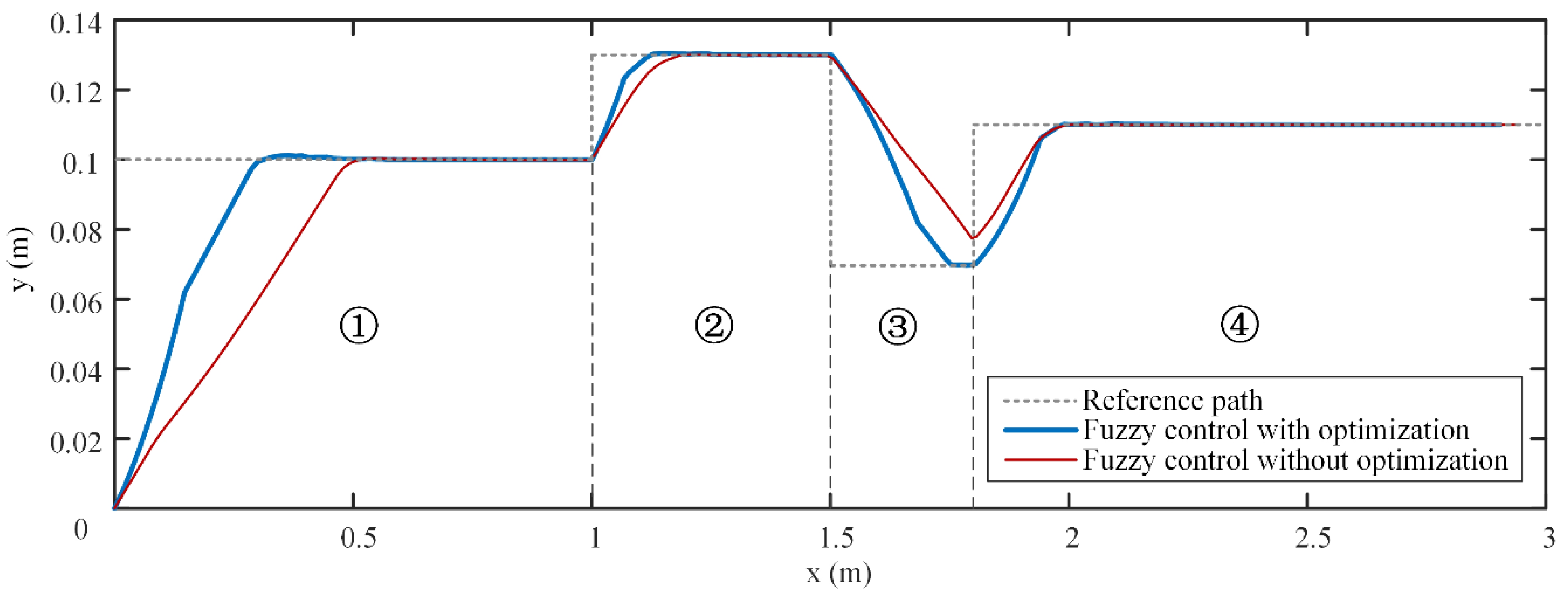
In the first simulation, the proposed fuzzy controller with online optimization of the scale factors using the fusion BA was applied to track a reference path with abrupt displacement, which imitates the condition where an embossment of the biofouling boundary appears or disappears in the view of the UPCR. As a contrast, the fuzzy controller without optimization was also simulated, and Kpos, Kori, and Kt were set as 1000, 0.35, and 7, respectively. Figure 9 and Figure 10 show the tracking performance of these two fuzzy controllers when the velocity of the front wheel of the UPCR is 3.6 m/min.
As shown in Figure 9, both fuzzy controllers can successfully drive the UPCR to track the reference path. When initial conditions for both controllers were the same in stages ① and②, the UPCR with the optimized fuzzy controller moved close to the reference path more quickly. As the reference path was short in stage ③, the UPCR with the conventional fuzzy controller did not have enough time to finish adjusting. In stage ④, although the initial deviation for the optimized fuzzy controller was bigger than that for the conventional fuzzy controller, both fuzzy controllers spent almost the same time to eliminate errors.
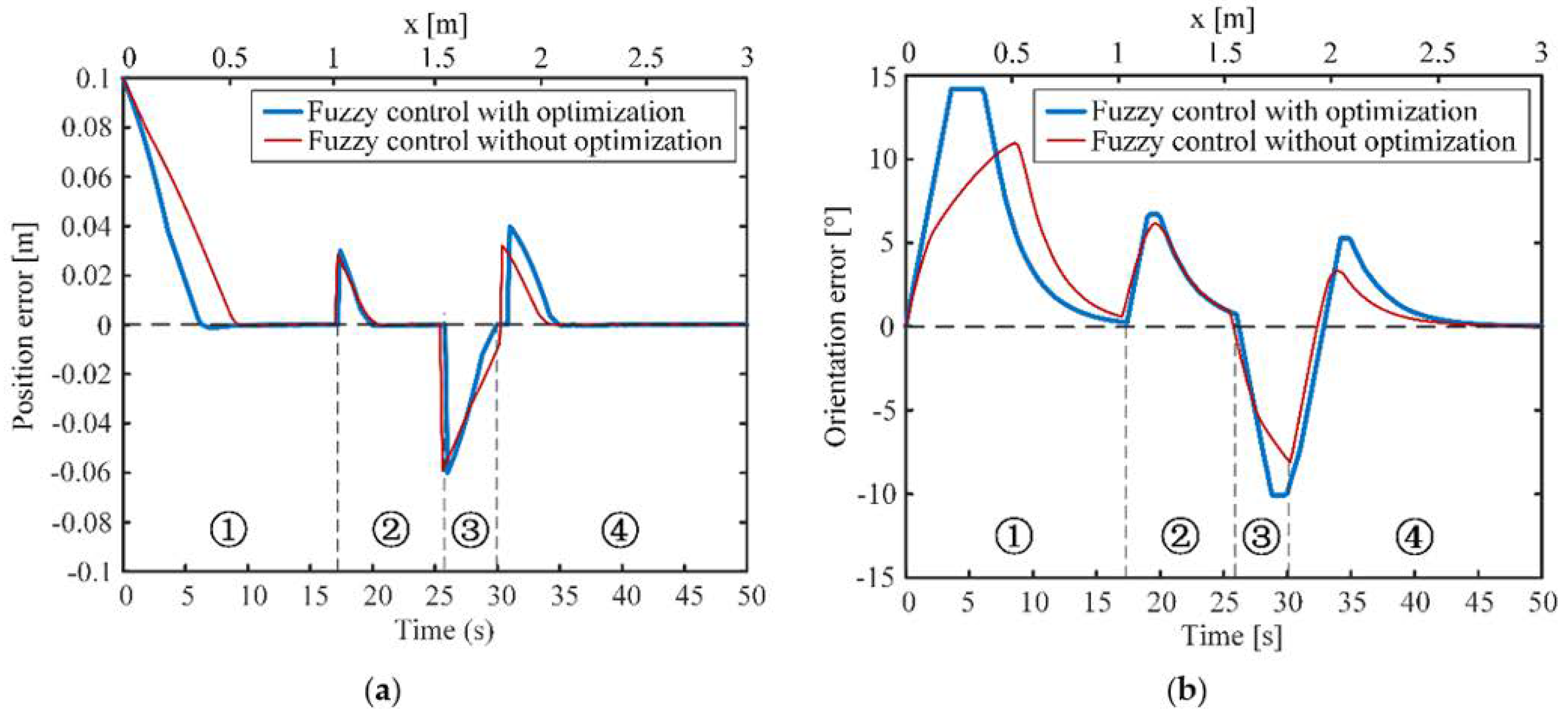
Figure 10a,b shows the position error and the orientation error with respect to time and mileage along the x-axis, which represent the speed of the nozzle approaching the reference line and the UPCR straightening its body along the reference line, respectively. From the result, it takes more than 10 s for the UPCR to eliminate large position and orientation errors. This phenomenon is reasonable because the robot has to move slowly to ensure that the sea creatures are fully cleaned and the drive motor provides enough torque to overcome the resistance caused by magnetic adsorption. It should also be noted that the maximum orientation error was bigger when the UPCR used the optimized fuzzy controller, which is because the weight coefficient ω1 was set to be bigger than ω2 to decrease the position error as a priority, and a faster change of position in the left–right direction of the UPCR required a bigger orientation error. Despite all this, the correction of the orientation error was still faster using the optimized fuzzy controller, as shown in Figure 10b. In general, the proposed fuzzy controller is suitable for the tracking path task and optimizing its scale factors online can dramatically improve the performance.
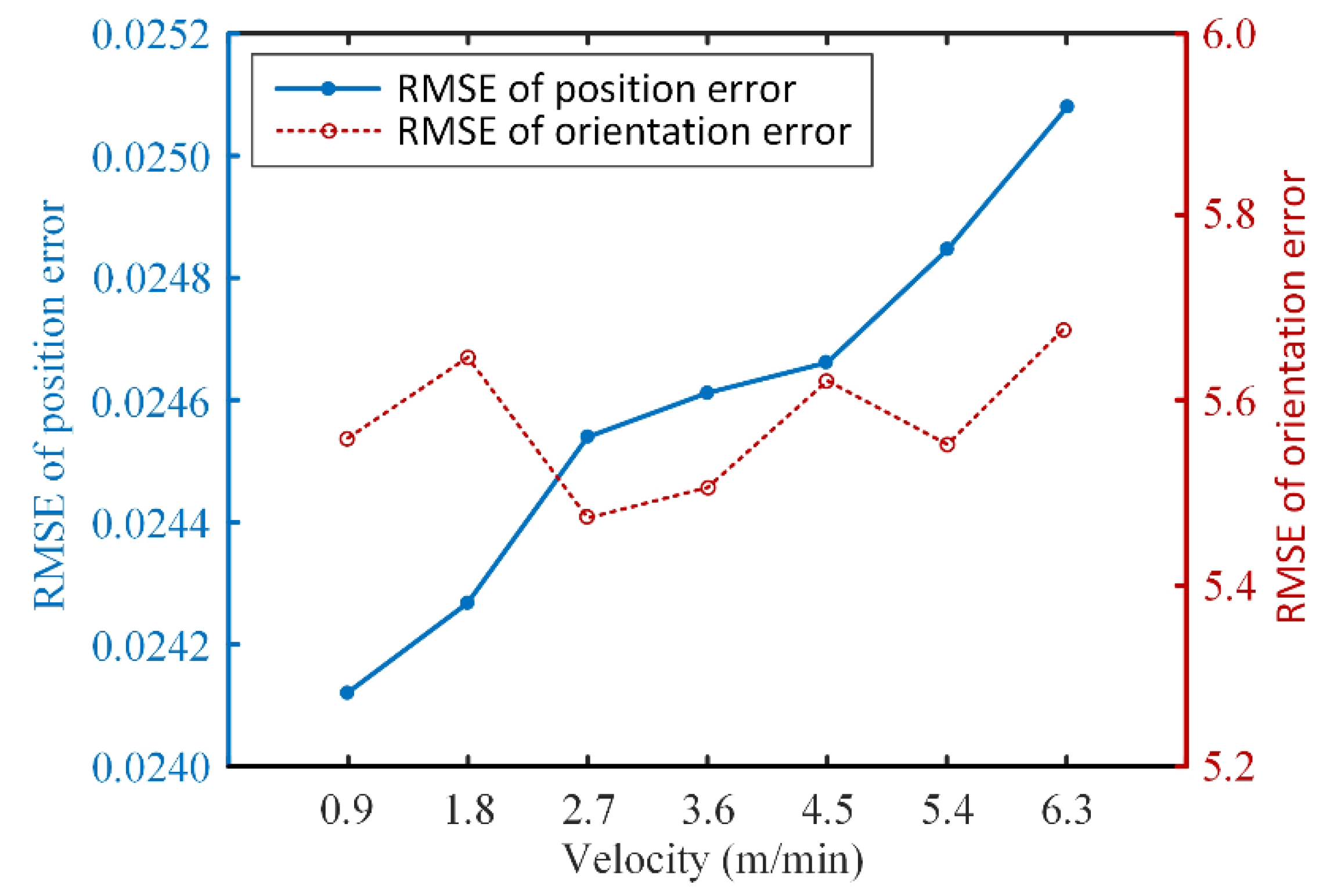
In order to explore the sensitivity of the proposed controller to the moving speed of the UPCR, we simulated its tracking performance at different speeds. Each simulation was performed under the same setting (e.g., reference trajectory and dynamic parameters). Figure 11 shows the root mean square error (RMSE) of the UPCR’s performance error at seven different moving speeds. From the result, the RMSE of the position error increases with UPCR’s speed, whereas the RMSE of the orientation error has no obvious relationship with the robot’s speed. This result indicates that, within a certain velocity range, the tracking performance of the UPCR is inversely related to its moving speed. However, the RMSE of the tracking performance did not change significantly within such a large velocity range. Considering that the velocity of the robot in most applications is between 1.8 and 3.6 m/s, it can be concluded that the fusion bat algorithm-optimized fuzzy controller is suitable for the UPCR.
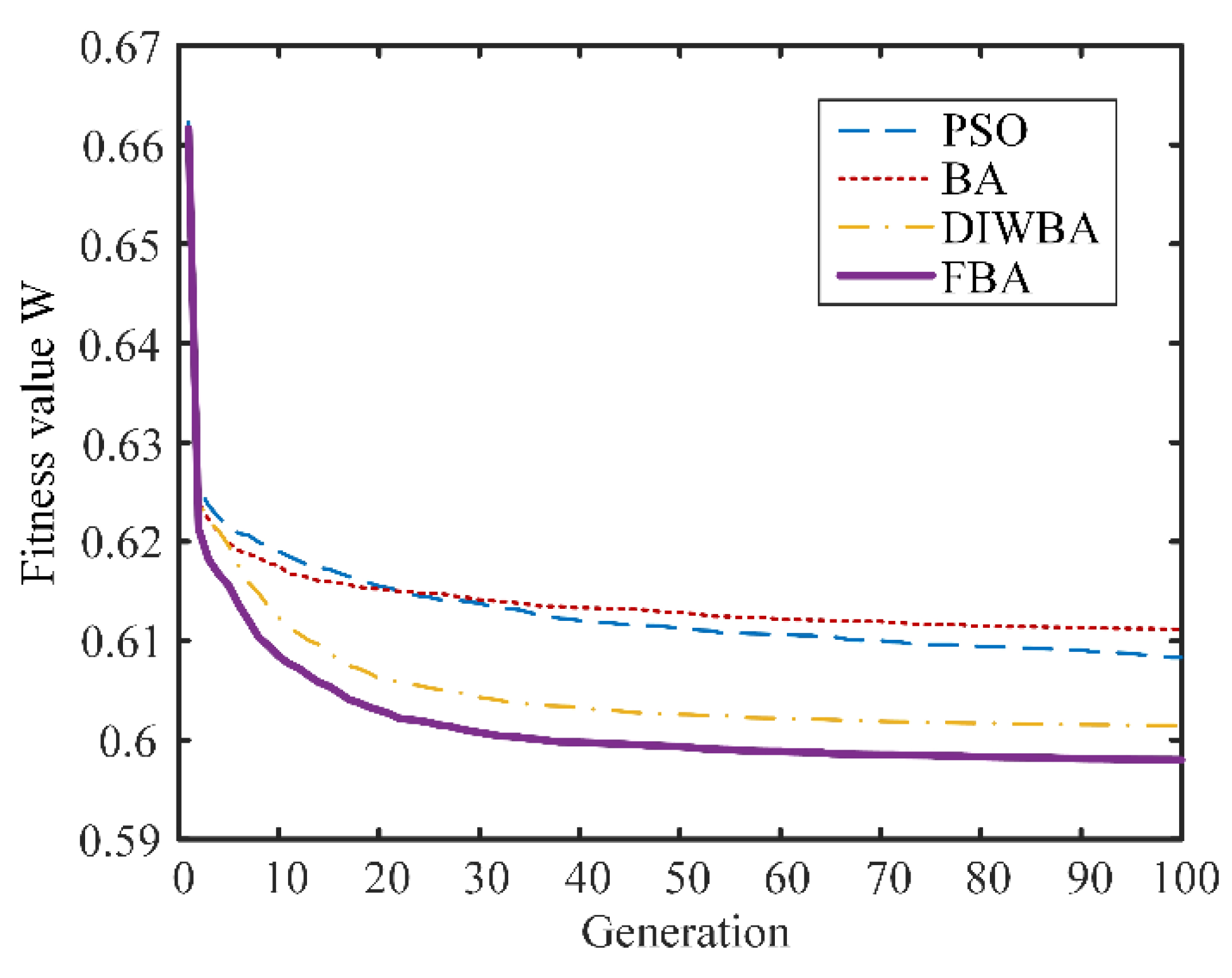
To verify the superiority of the fusion BA, a second simulation was conducted to compare the performance of the fusion BA (FBA), the BA with only the dynamic inertia weight (DIWBA), the conventional BA, and the PSO. The initial conditions for each method were the same, and the simulation was repeated 100 times. According to the results shown in Figure 12, the proposed fusion BA converges to the optimal solution with a faster convergence speed and a better fitness value, which guarantees better real-time performance of the control system.

5. Experiment and Results

The vision-based optimized fuzzy control method was applied to drive the UPCR following the boundary of an area covered by biofouling, which were simulated by shells and paint on a pipe in the laboratory. The localization algorithm and the control algorithm were run in the computer and their processing times were about 41 ms and 60 ms, respectively. In order to decrease the influence of the time delay of communication, the control time step was chosen as 0.3 s and the velocity of the front wheel was set as 1.8 m/min.
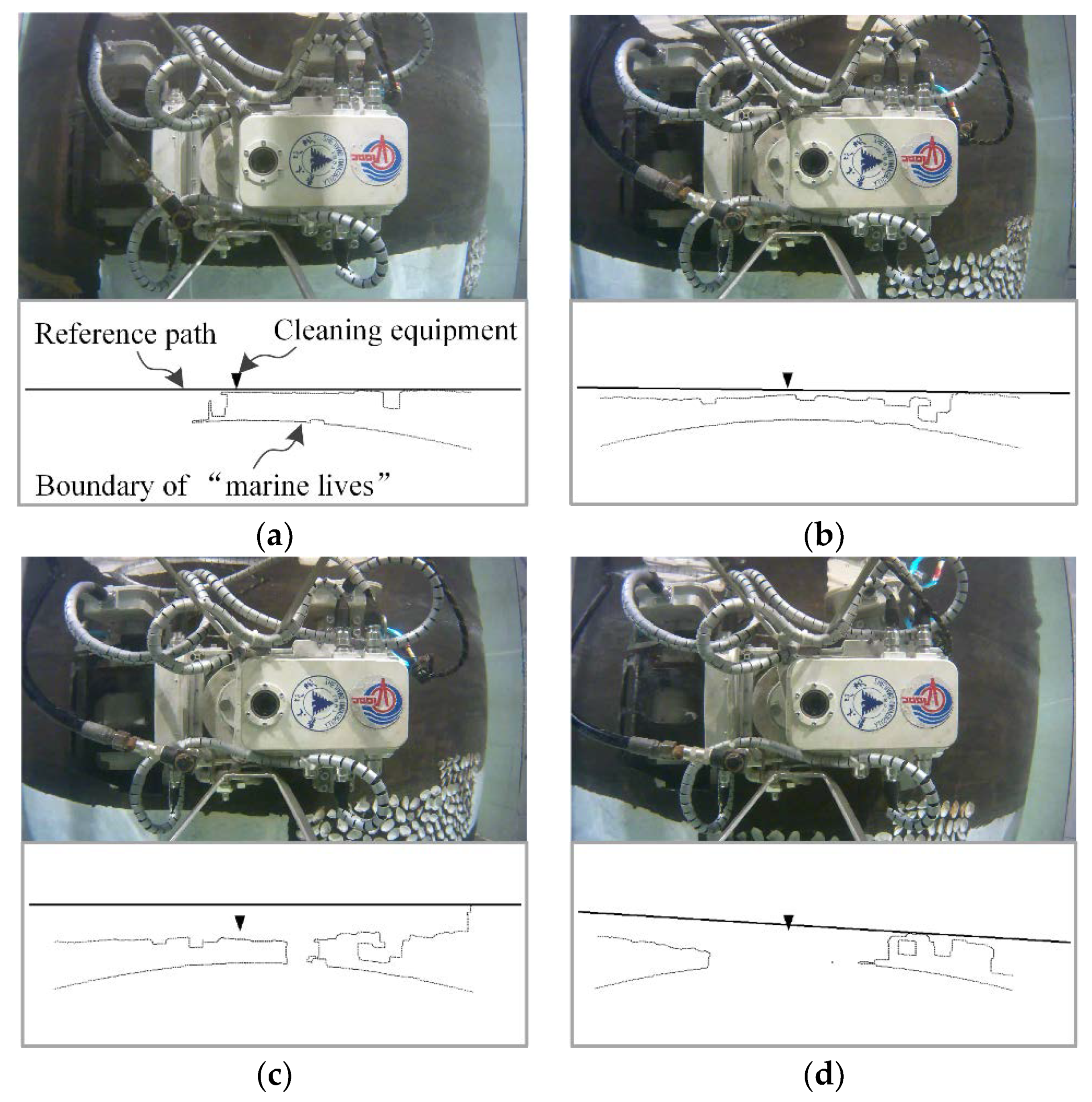
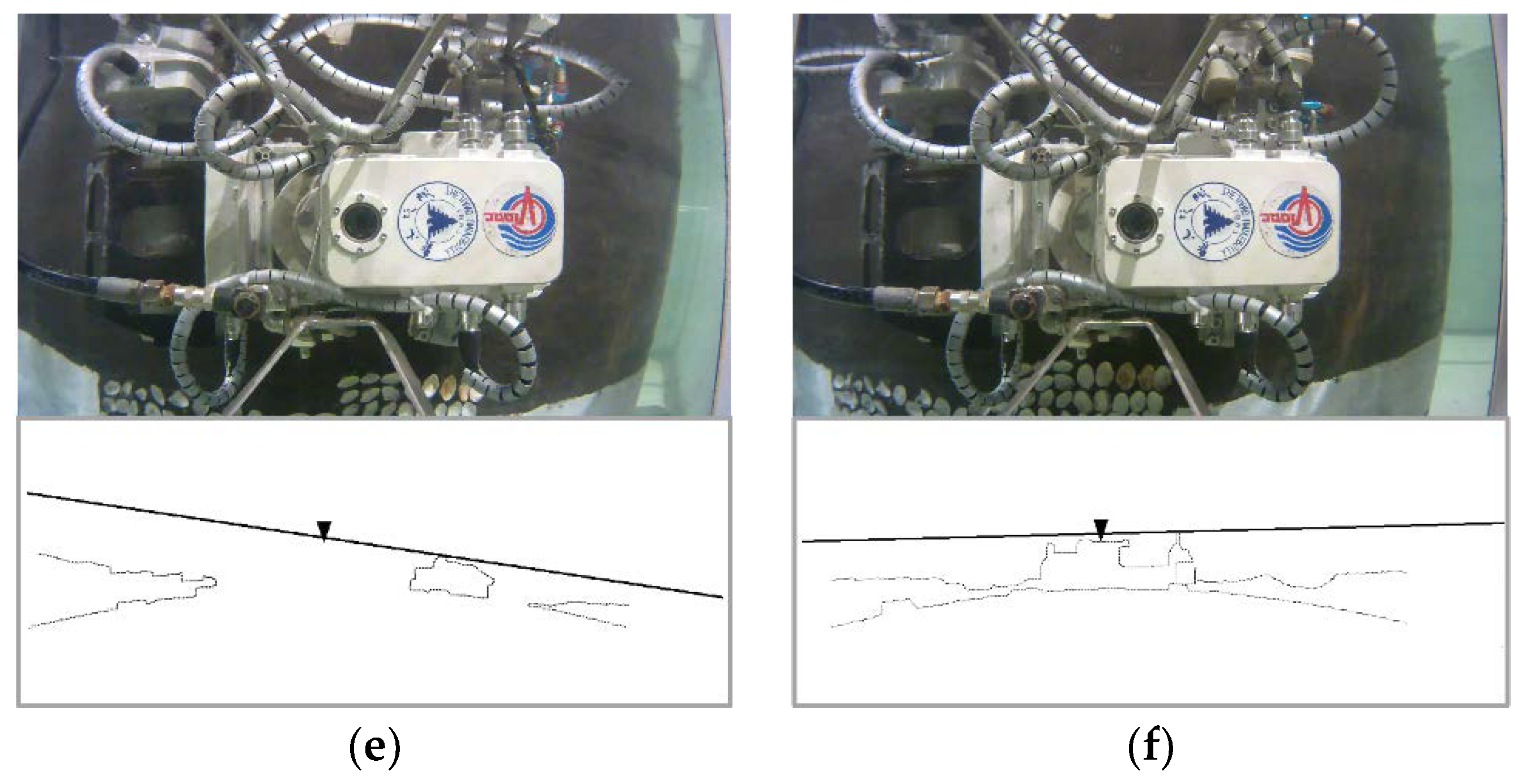
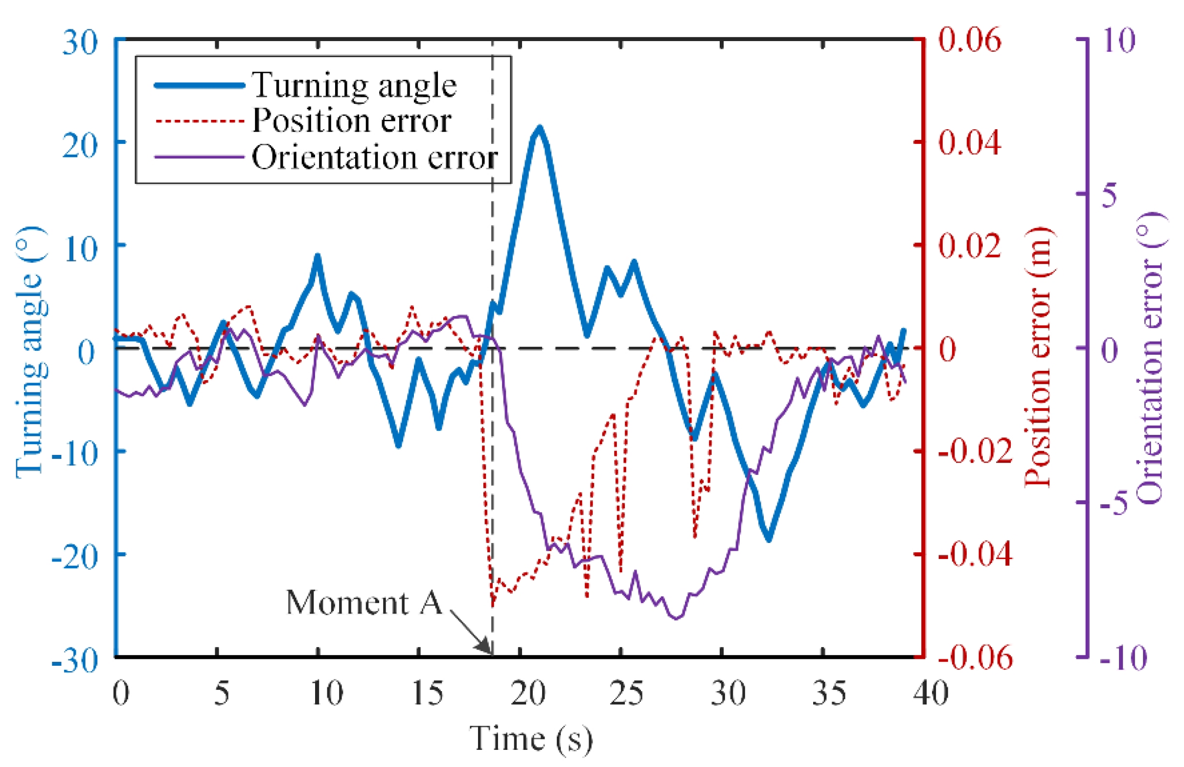
Figure 13 shows the UPCR’s movement during the experiment. The upper parts of the subgraphs are the images captured by the catadioptric panoramic imaging system and the lower parts indicate the localization results that point to the biofouling boundary on the pipe, presented on the plane by surface flattening. The tracking errors and the UPCR’s turning angle during the experiment are shown in Figure 14. It can be seen that the UPCR moved forward as the boundary was almost flat (Figure 13a,b), and the position error and the orientation error were no more than 0.01 m and 2°, respectively. When the UPCR detected the embossment of the boundary at moment A, the reference path changed and a big position error occurred (Figure 13c). Then, the UPCR automatically tracked the new reference path to avoid crashing, as we expected (Figure 13d–f). Due to the selection strategy of the feature point, the reference path can be generated correctly under most circumstances, even though part of the biofouling was not recognized. According to Figure 14, the changing trend of the tracking error was similar to the simulation results in Section 4 where the position error was preferentially corrected. The setting time was a little longer than that in the simulations as there were some measurement mistakes in the position error. The experimental results indicate the rationality and validity of the control method presented above.

6. Conclusions

This paper describes a new BA online optimized fuzzy control method for a UPCR based on vision localization. Constraints of the working environment were analyzed, and a localization system composed of global localization and local localization and a fuzzy controller with fusion BA were proposed. The local localization was achieved based on images from a catadioptric panoramic imaging system. The features of the pipe edge and the boundary of the area covered by biofouling were obtained by image processing and feature extraction, and then the reference path was generated based on the coordinates of the feature point that was calculated by projection transformation. The fuzzy controller was designed to make the UPCR track the reference path, and an improved BA with dynamic inertia weight and differential evolution method was developed to optimize the scale factors of the fuzzy controller online. Simulations and experiments were performed to demonstrate the validity of the proposed method.
As the operational condition of the UPCR (i.e., the irregular offshore structure covered by biofouling) is more complex and varied, future works will focus on improving the robustness and accuracy of vision localization in order to conduct field applications in the sea.

Author Contributions

Y.C., conception of the study, analysis and manuscript preparation; S.L., performed the experiment; J.F., contributed significantly to the data analyses and wrote the manuscript; C.Y. helped perform the analysis with constructive discussions and provided funding. All authors have read and agreed to the published version of the manuscript.

Funding

This work was supported by the National Natural Science Foundation of China (No. 51979246), the Key Research and Development Program of Zhejiang Province (No. 2019C03101), and the Natural Science Foundation of Zhejiang Province of China (No. LY18E090003).

Conflicts of Interest

The authors declare that they have no known competing financial interests or personal relationships that could have appeared to influence the work reported in this paper.

References

  1. Callow, J.A.; Callow, M.E. Trends in the development of environmentally friendly fouling-resistant marine coatings. Nat. Commun. 2011, 2. [Google Scholar] [CrossRef] [PubMed]
  2. Dong, S.; Bai, X.; Yuan, C. Analysis of induced corrosion by fouling organisms on offshore platform and its research progress. Mater. Prot. 2018, 51, 116–124. [Google Scholar] [CrossRef]
  3. Albitar, H.; Dandan, K.; Ananiev, A.; Kalaykov, I. Underwater Robotics: Surface Cleaning Technics, Adhesion and Locomotion Systems. Int. J. Adv. Robot. Syst. 2016, 13. [Google Scholar] [CrossRef] [Green Version]
  4. Yi, Z.; Gong, Y.; Wang, Z.; Wang, X.; Zhang, Z. Large wall climbing robots for boarding ship rust removal cleaner. Robot 2010, 32, 560–567. [Google Scholar] [CrossRef]
  5. Nassiraei, A.A.F.; Sonoda, T.; Ishii, K. Development of ship hull cleaning underwater robot. In Proceedings of the International Conference on Emerging Trends in Engineering and Technology, Himeji, Japan, 5–7 November 2012; pp. 157–162. [Google Scholar]
  6. Souto, D.; Faina, A.; Lopez-Pena, F.; Duro, R.J. Morphologically intelligent underactuated robot for underwater hull cleaning. In Proceedings of the 2015 IEEE 8th International Conference on Intelligent Data Acquisition and Advanced Computing Systems: Technology and Applications, IDAACS 2015, Warsaw, Poland, 24–26 September 2015; Volume 2, pp. 879–886. [Google Scholar]
  7. Hachicha, S.; Zaoui, C.; Dallagi, H.; Nejim, S.; Maalej, A. Innovative design of an underwater cleaning robot with a two arm manipulator for hull cleaning. Ocean Eng. 2019, 181, 303–313. [Google Scholar] [CrossRef]
  8. Albitar, H.; Ananiev, A.; Kalaykov, I. In-water surface cleaning robot: Concept, locomotion and stability. Int. J. Mechatron. Autom. 2014, 4, 104–115. [Google Scholar] [CrossRef]
  9. Fan, J.; Yang, C.; Chen, Y.; Wang, H.; Huang, Z.; Shou, Z.; Jiang, P.; Wei, Q. An underwater robot with self-adaption mechanism for cleaning steel pipes with variable diameters. Ind. Rob. 2018, 45, 193–205. [Google Scholar] [CrossRef]
  10. Gong, Y.; Sun, L.; Zhang, Z.; Gu, X.; Li, G. Design and application of ultra-high pressure water jet ship rust equipment. In Proceedings of the IEEE International Conference on Fluid Power and Mechatronics, Beijing, China, 17–20 August 2011; pp. 359–363. [Google Scholar]
  11. Psarros, D.; Papadimitriou, V.; Chatzakos, P.; Spais, V.; Chrysagis, K. A service robot for subsea flexible risers. IEEE Robot. Autom. Mag. 2010, 17, 55–63. [Google Scholar] [CrossRef]
  12. Ross, B.; Bares, J.; Fromme, C. A semi-autonomous robot for stripping paint from large vessels. Int. J. Rob. Res. 2003, 22, 617–626. [Google Scholar] [CrossRef]
  13. Juliá, M.; Gil, A.; Reinoso, O. A comparison of path planning strategies for autonomous exploration and mapping of unknown environments. Auton. Robots 2012, 33, 427–444. [Google Scholar] [CrossRef]
  14. Tache, F.; Pomerleau, F.; Caprari, G.; Siegwart, R.; Bosse, M.; Moser, R. Three-dimensional localization for the MagneBike inspection robot. J. Field Robot. 2011, 28, 180–203. [Google Scholar] [CrossRef]
  15. Stumm, E.; Breitenmoser, A.; Pomerleau, F.; Pradalier, C.; Siegwart, R. Tensor-voting-based navigation for robotic inspection of 3D surfaces using lidar point clouds. Int. J. Rob. Res. 2012, 31, 1465–1488. [Google Scholar] [CrossRef]
  16. Okamoto, J.; Grassi, V.; Amaral, P.F.S.; Pinto, B.G.M.; Pipa, D.; Pires, G.P.; Martins, M.V.M.I. Development of an autonomous robot for gas storage spheres inspection. J. Intell. Robot. Syst. 2012, 66, 23–35. [Google Scholar] [CrossRef]
  17. Cho, C.; Kim, J.; Lee, S.; Lee, S.K.; Han, S.; Kim, B. A study on automated mobile painting robot with permanent magnet wheels for outer plate of ship. In Proceedings of the IEEE International Symposium on Robotics, Seoul, Korea, 24–26 October 2013. [Google Scholar]
  18. Zhang, K.; Chen, Y.; Gui, H.; Li, D.; Li, Z. Identification of the deviation of seam tracking and weld cross type for the derusting of ship hulls using a wall-climbing robot based on three-line laser structural light. J. Manuf. Process. 2018, 35, 295–306. [Google Scholar] [CrossRef]
  19. Zhang, L.; Sun, J.; Yin, G.; Zhao, J.; Han, Q. A cross structured light sensor and stripe segmentation method for visual tracking of a wall climbing robot. Sensors 2015, 15, 13725–13751. [Google Scholar] [CrossRef] [Green Version]
  20. Zhang, L.; Ke, W.; Ye, Q.; Jiao, J. A novel laser vision sensor for weld line detection on wall-climbing robot. Opt. Laser Technol. 2014, 60, 69–79. [Google Scholar] [CrossRef]
  21. Teixeira, M.A.S.; Santos, H.B.; Dalmedico, N.; de Arruda, L.V.R.; Neves, F., Jr.; de Oliveira, A.S. Intelligent environment recognition and prediction for NDT inspection through autonomous climbing robot. J. Intell. Robot. Syst. 2018, 92, 323–342. [Google Scholar] [CrossRef]
  22. Tavakoli, M.; Lopes, P.; Sgrigna, L.; Viegas, C. Motion control of an omnidirectional climbing robot based on dead reckoning method. Mechatronics 2015, 30, 94–106. [Google Scholar] [CrossRef]
  23. Kim, J.H.; Lee, J.C.; Choi, Y.R. LAROB: Laser-guided underwater mobile robot for reactor vessel inspection. IEEE/ASME Trans. Mechatron. 2014, 19, 1216–1225. [Google Scholar] [CrossRef]
  24. Jiang, P.; Yang, C.; Shou, Z.; Chen, Y.; Fan, J.; Huang, Z.; Wei, Q. Research on vision-inertial navigation of an underwater cleaning robot. J. Cent. South Univ. Sci. Technol. 2018, 49, 52–58. [Google Scholar] [CrossRef]
  25. Wang, H.; Yang, C.; Deng, X.; Fan, J. A simple modeling method and trajectory planning for a car-like climbing robot used to strip coating from the outer surface of pipes underwater. In Proceedings of the 18th International Conference on Climbing and Walking Robots and the Support Technologies for Mobile Machines, CLAWAR 2015, Hangzhou, China, 6–9 September 2015; pp. 704–712. [Google Scholar]
  26. Wang, Z.; Zhang, K.; Chen, Y.; Luo, Z.; Zheng, J. A real-time weld line detection for derusting wall-climbing robot using dual cameras. J. Manuf. Process. 2017, 27, 76–86. [Google Scholar] [CrossRef]
  27. Heath, M.D.; Sarkar, S.; Sanocki, T.; Bowyer, K.W. A robust visual method for assessing the relative performance of edge-detection algorithms. IEEE Trans. Pattern Anal. Mach. Intell. 1997, 19, 1338–1359. [Google Scholar] [CrossRef] [Green Version]
  28. Moustris, G.P.; Tzafestas, S.G. Switching fuzzy tracking control for mobile robots under curvature constraints. Control Eng. Pract. 2011, 19, 45–53. [Google Scholar] [CrossRef]
  29. Chen, Z.; Huang, F.; Sun, W.; Gu, J.; Yao, B. RBF neural network based adaptive robust control for nonlinear bilateral teleoperation manipulators with uncertainty and time delay. IEEE/ASME Trans. Mechatron. 2019. [Google Scholar] [CrossRef]
  30. Xiao, J.; Xiao, J.Z.; Xi, N.; Tummala, R.L.; Mukherjee, R. Fuzzy controller for wall-climbing microrobots. IEEE Trans. Fuzzy Syst. 2004, 12, 466–480. [Google Scholar] [CrossRef]
  31. Yang, X.S.; Gandomi, A.H. Bat algorithm: A novel approach for global engineering optimization. Eng. Comput. 2012, 29, 464–483. [Google Scholar] [CrossRef] [Green Version]
  32. Huang, H.C. Fusion of Modified Bat Algorithm Soft Computing and Dynamic Model Hard Computing to Online Self-Adaptive Fuzzy Control of Autonomous Mobile Robots. IEEE Trans. Ind. Inform. 2016, 12, 972–979. [Google Scholar] [CrossRef]
  33. Xue, F.; Cai, Y.; Cao, Y.; Cui, Z.; Li, F. Optimal parameter settings for bat algorithm. Int. J. Bio-Inspired Comput. 2015, 7, 125–128. [Google Scholar] [CrossRef]
  34. Mendes, R.; Mohais, A.S. DynDE: A Differential Evolution for dynamic optimization problems. 2005 IEEE Congr. Evol. Comput. 2005, 3, 2808–2815. [Google Scholar] [CrossRef] [Green Version]
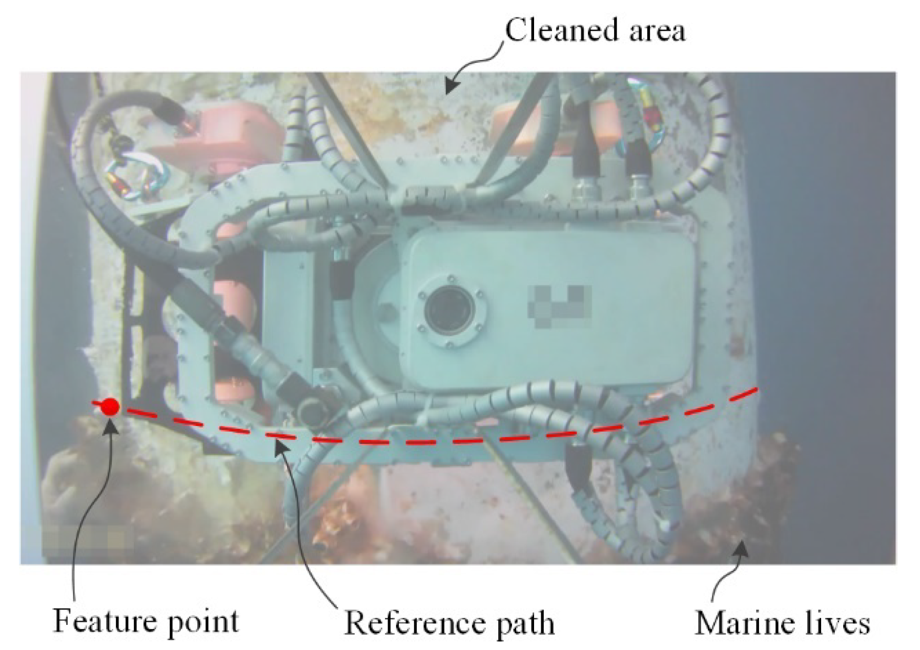
Figure 1. Schematic diagram of the feature point and the reference path.
Applsci 10 04279 g001
Figure 2. Overview of the underwater pipe-cleaning robot (UPCR). Left is the UPCR prototype. Right is the front view, which shows the structure of the catadioptric panoramic imaging system and its position relative to the biofouling during cleaning operations.
Applsci 10 04279 g002
Figure 3. Operational trajectory of the UPCR. dp is the distance of adjacent circles and also the effective cleaning scale of the cavitation water jet.
Applsci 10 04279 g003
Figure 4. Process of the feature extraction.
Applsci 10 04279 g004
Figure 5. Schematic of the projection transformation: (a) Left view, (b) Top view.
Applsci 10 04279 g005
Figure 6. Schematic diagram of the fuzzy controller with fusion bat algorithm (BA).
Applsci 10 04279 g006
Figure 7. Membership functions of the fuzzy controller: (a) Inputs, (b) Output.
Applsci 10 04279 g007
Figure 8. Pseudo code of the fusion BA.
Applsci 10 04279 g008
Figure 9. The UPCR path under the two fuzzy control methods and the reference path in the first simulation.
Applsci 10 04279 g009
Figure 10. Tracking error of the UPCR using the two fuzzy controllers in the first simulation: (a) Position error, (b) Orientation error.
Applsci 10 04279 g010
Figure 11. Root mean square error (RMSE) of the performance error at different moving speeds.
Applsci 10 04279 g011
Figure 12. Evolution of fitness value in the fusion BA (FBA) and the other three methods to optimize the scale factors.
Applsci 10 04279 g012
Figure 13. The UPCR automatically tracking the boundary of simulated biofouling: (a,b) Tracking the straight line, (c) Detecting the embossment, (d–f) Avoiding crashing and tracking the new line.
Applsci 10 04279 g013aApplsci 10 04279 g013b
Figure 14. Tracking errors and turning angle of the reference path tracking.
Applsci 10 04279 g014
Table 1. Fuzzy rules of the fuzzy controller for path tracking.
eposNBNMNSZOPSPMPB
αt
eori
NBZONSNMNBNBNBNB
NMZOZONSNMNMNBNB
NSPSZOZONSNMNMNB
ZOPMPSPSZONSNSNM
PSPBPMPMPSZOZONS
PMPBPBPMPMPSZOZO
PBPBPBPBPBPMPSZO