1. Introduction
The need for the reduction in our carbon footprint has coincided with upward fuel prices, which has prompted an increased focus in the search for energy-saving solutions related to the transportation sector. Hence, unleashing the maximum potential of hybrid and electric vehicles at different fleet and standalone energy management design levels is at the forefront of research in the automotive industry [
1,
2,
3]. The energy management strategy (EMS) unit is the heart of power sharing control toward addressing the consumption-friendly objectives of electric vehicle design. Compared to their conventional counterparts, hybrid electric vehicles (HEVs) can offer lower fuel consumption and still provide a similar/enhanced performance. However, as HEVs usually comprise two or more energy supply sources, developing their architectures with an efficient EMS involves a plethora of complexities related to design, integration, and implementation. Due to these cost-effective complexities, the plausibility of any control strategy requires assessment through various testing and validation procedures before embedment in the electronic control unit (ECU) of an on-road vehicle [
4]. In this regard, the response and accuracy of a control strategy is of great significance for extensive verification through the use of a complete chain of tools. Toward real-world applicability, the model-based design of a plant and its EMS include various steps from the development to validation phases. This generally starts with functional system definitions and ends with deploying the design to a real operating environment under offline system modeling, control algorithm synthesis, simulation analysis, and online vehicle implementations [
5]. To this end, first, a model-in-the-loop (MiL) development must be performed in which the integrated plant and the corresponding EMS controller models are built and set up in a desktop environment (i.e., MATLAB/Simulink
®) to be examined over a complete driving cycle. This considers a totally software-based and iterative trial and error approach toward achieving an initial design with good flexibility and low cost in a short period [
6]. In this phase, it is possible to perform fast EMS design alternations to investigate corresponding effects on a set of predefined objectives.
Thereafter, through software-in-the-loop (SiL) evaluations, one can test the plant and controller models in a slightly more realistic environment as the corresponding C/C++ code can be generated for digital implementation tests. The possibility of design modification in this stage is slower time-wise as there is a need to go back, modify the initial model, and regenerate the C/C++ code if required. This step is of great importance to test the feasibility of the built code in terms of real-time evaluation. In this regard, convertibility of the control algorithms to C/C++ code assures that they are downloadable into digital signal processing (DSP) boards (e.g., dSPACE rapid prototyping product, “MiroLab Box”) for processor-in-the-loop (PiL) tests as a next phase. The PiL phase considers hardware features and provides realistic situations by running the control algorithm for an emulated target behavior [
7]. Hence, these steps can not only reveal coding failures, but also provide helpful insights for the hardware-in-the-loop (HiL) implementation where the vehicle behavior can be reproduced.
In the HiL phase, the developed control algorithms with mathematical models running in real-time can be fully installed on a control hardware to communicate and actuate real/emulated components. A typical HiL system integrates various software and hardware-based units such as physical components (not in all testbeds), component emulators, DSP/FPGA unit, MATLAB/Simulink
® desktop environment, real-time interface (RTI), real-time workshop (RTW), and controller area network (CAN) [
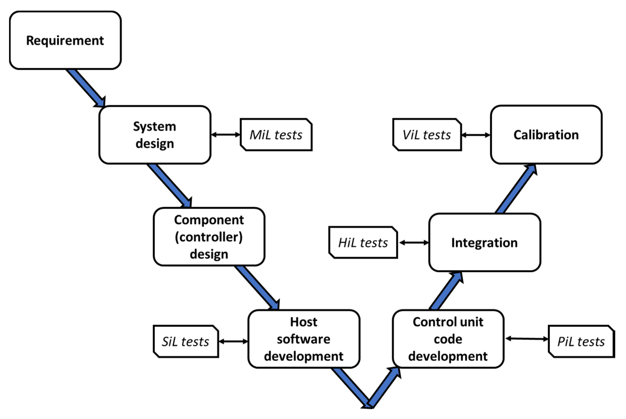
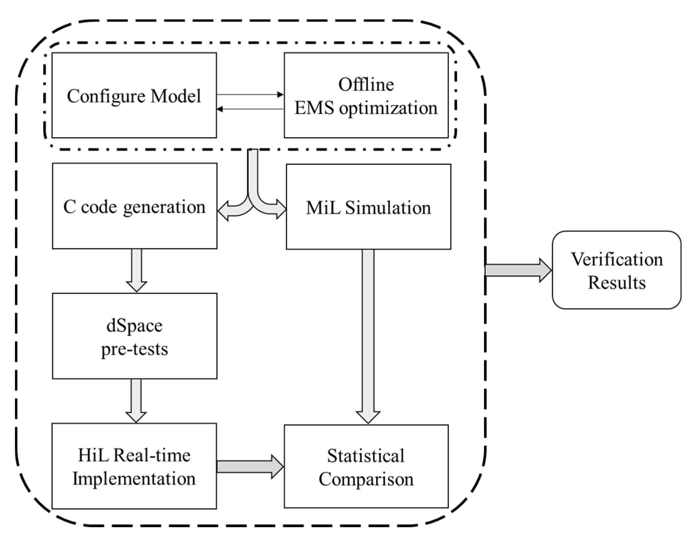
8]. In the HiL implementation stage, exerted road load on wheels can be manipulated in a real-time manner by introducing an input driving cycle to the physical testbed to examine operating conditions as if in a real driving environment. The main objective of HiL implementation is to experimentally test and verify the feasibility, accuracy, high dynamic response, scalability, and reliability merits of a designed control algorithm to guarantee its real-world applicability. The HiL test ensures savings in design cost and time by reducing the total development cycle of vehicle calibration as it indicates how an EMS control unit, and consequently the plant’s components, will communicate and behave in a real vehicle. In other words, it provides a validation method for development engineers for the safety and precision of the control system before an actual mule vehicle is available. Hence, once an EMS is designed and verified in a closed-loop manner through HiL, it can ideally be transmitted to a vehicle-in-the-loop (ViL) testbed without design modifications, expecting that the proposed strategy can represent identical features. Considering the discussed phases,
Figure 1 recapitulates the chronological design steps known as the “V” development process [
7].
Although the effectiveness of various EMS algorithms has been extensively reported in previously performed studies, many have been limited to an early EMS design stage (i.e., MiL) of the studied topologies. There has been a tremendous interest in the development of these virtually tested models mainly based on optimization-based (OB) and rule-based (RB) techniques, but in the absence of real-time implementation. Instead, the main outcomes have compared the validity and competency of approaches in addressing the non-linearities/multimodalities of non-convex objectives such as fuel consumption enhancement and battery charge-sustaining in a fully software-based way. For example, in [
9], objectives such as battery charge-sustaining and improving fuel economy were considered using a RB EMS, and power distribution through the vehicle components were investigated. In another study [
10], different RB strategies were compared in terms of fuel consumption improvements, and the computational costs of the RB EMSs were evaluated through a comparison for a use-case of parallel HEV topology in [
11]. In another study [
12], the battery state of charge (SoC) control, power flow, and fuel consumption were evaluated through a RB power split method considering the engine operating points. The SoC pattern evolutions were investigated in [
13] using a RB supervisory control approach, and in [
14], a driving cycle recognition method was employed to improve fuel efficiency. Huang et al. [
15] performed an optimization of the control strategy parameters for a series HEV topology to minimize the fuel consumption. In that study, different OB techniques were compared for optimal EMS design in a MATLAB/Simulink
® environment where the results indicated the superiority of genetic algorithm (GA) compared to DIRECT and thermostatic (On/Off) methods. In another study, Montazeri and Poursamad [
16] proposed an OB EMS of HEVs by aggregating the constraints into the objective function. In that study, penalty functions were used to weed out the infeasible solutions and minimize fuel consumption and emissions. Gao et al. [
17] used GA in a PSAT environment for powertrain optimization of a parallel HEV topology to improve the overall fuel economy. Salmasi [
18] for HEVs and Martinez et al. [
19] for plug-in HEVs classified and overviewed control strategies including various RB and OB methods, leading to future trends in the field. The equivalent consumption minimization strategy (ECMS) was incorporated into driving cycle prediction, performing horizon optimizations, and pattern recognition concepts in [
20,
21] to provide efficient power splitting. Along the same line, ECMS approaches have been proposed that rely on considering instantaneous SoC values to be used as state feedback to control the battery SoC variation for charge-sustaining [
22,
23,
24].
In contrast to the above-mentioned studies, researchers have taken investigations to a next level by carrying out experimental examination of EMSs through HiL tests to address their real-time performance and applicability. However, among these studies, many have been limited in terms of including testbeds that can represent a drivetrain architecture in a high-fidelity manner. In other words, in these test benches, fast prototyping of equivalent drivetrains by using hardware-based simulators/interfaces were considered instead of including mechanical (e.g., rotatory machines) and electrical (e.g., battery, inverters, and converters) prototyped components. For example, in [
8], a HiL test system without prototyped components and based on a standalone dSPACE and control desk was employed to verify the real-time capability of an ECMS-based approach versus the simulation results proposed for a hybrid city bus. In another study, the typical control strategies of two passenger HEVs, a Jeep Commander and Toyota Prius, were tested through a university HiL testbed with limitations on the maximum torque and speed measurement [
25]. In that test bench, the objective was to combine relatively low-cost off-the-shelf products to examine the test environment and realize phases of real-time data acquisition, signal generation, automatic code generation, and power measurements using MATLAB/Simulink
®, dSPACE, and a Hioki power analyzer. The applicability of combining RB and OB EMS control were proposed in [
26], while the experimentally-determined parameters of the components were considered instead of real drivetrain components for considering motor/generator dynamics and battery. Li et al. [
5] performed a HiL analysis for EMS of a parallel HEV by a rapid prototyping approach. They investigated low-level ECUs coupled to a dSPACE HiL simulator to virtually capture and actuate signals for the engine and motor’s torque-speed operating pairs over a full driving cycle. Wu et al. [
27] combined embedded and software-based simulations to verify the feasibility of a HiL methodology for a supervisory control downloaded into a midsize HiL machine including a load emulator card. This semi-physical study was performed based on a practical application of dSPACE products to provide ECU development as a progress phase. In that study, it was reported that including other physical units to their test bench was required for further realistic verification tests. The components of a series–parallel hybrid electric city-bus were modeled in MATLAB/Simulink
® by Wang et al. [
28] and its EMS was tested. In that study, a commercial HiL simulator, PT-LABCAR, in the presence of a real control unit, were used, while the engine, motor. and battery were emulated in a software-based manner. To verify the control, the actual and setpoint speed of the final drive were compared. However, similar comparisons are essential for other crucial features (i.e., torque and rotational speed) to confirm the controllability, power sharing competency, and actuation response of an EMS in a more comprehensive way. The torque and speed of the engine and motor obtained from the HiL and MiL tests were compared for real-time verification of EMS control for a GM Chevrolet Volt case study by Algarny et al. [
29]. The objective of their study was to validate the physical control signals generated by EMS while the components were emulated by mathematical models. In that study, a low-level simple HiL test bench including a TI controller and oscilloscope were used where Typhoon HiL, aside from the PSIM software environments, were used as the interface and model generator, respectively. Chako et al. [
30] used a custom real-time simulator platform and a DSP control card to introduce a HiL testbed for the academic development of control algorithms where a Simulink
® coder was used for real-time testing of a generated C code. The main objective of that study was only to test the control bench and generate measurable signals for features such as vehicle speed, acceleration, and power at the wheels. In another study [
31], a HiL module setup was tested for an inverter ECU and a software-based electric motor for HEVs. In that study, only the control board of the Inverter ECU (HIL Box) was physical, while the remaining components (i.e., HV battery, sensors, DC-link capacitor, electric motor, IGBT-based power electronics board, and drive load) were completely modeled in the MATLAB/FPGA environment.
Compared to the above-mentioned studies, considerable efforts have also been reported in the literature, which have taken verification tests to a more realistic and accurate level by adding up more physical degrees. In contrast to the semi-physical HiL test environments discussed, there have been studies that have included real prototyped components to provide more real-world and versatile test benches. These studies have focused on examining the mechanical/electrical actuation performance of components under real-time operations. Clearly, such a feature facilitates the testbed to include the existing losses of a system more accurately leading to reliable results from the setup. For example, Hui et al. [
6] presented a testbed including real components (i.e., internal combustion engine (ICE) and electric motor) for HiL implementation of HEV drivetrains while the battery and gearbox were realized by software models. Their ideally designed testbed employed an electromagnetic clutch, making the testbed switchable between series and parallel configurations. In another real-time study, Mayyas et al. [
32] examined ECMS-based and rule-based power splitting approaches in a roller bench emulating the driving cycle. In that study, the ICE and chassis system were integrated to become a part of a parallel HEV HiL testbed. The experimental HiL system in [
33] coupled a real engine with mathematical models of electric systems to verify the implementation of an ECMS-based control through comparisons of the MiL and HiL results for the engine torque. The behavior of fuel cell (FC) and super capacitor (SC), as real components of a multi-source HiL testbed, was assessed by Castings et al. [
34,
35], while battery and traction load parts were virtually emulated by a current source. The real-time system controllability was validated for an OB strategy in both of these studies. Allegre et al. [
36] reported a HiL implementation of an EV with real hybrid energy storage components comprising a battery and SC coupled into dSPACE and emulation choppers. Their experimental results validated the applicability of a low pass filter power sharing method considering a reduced-scale power.
As discussed in the current section, most studies have implemented HiL tests focusing on conventional HEV topologies such as series, parallel, and series-parallel. However, a very limited number of studies have reported on the HiL verification tests of EMSs for a recently promising topology of vehicles: HEVs equipped with EVT. For such a topology, most of the existing studies have reported offline results without assessing the system either in an experimental or realistic environment. In this regard, the EMSs for the power sharing control of EVT-based HEV topologies solely relying on MiL simulations were investigated in [
37,
38,
39]. On the other hand, there is experimental research that has focused on real-time implementations, but their objectives were limited to the design, testing, and optimization of EVT itself as a component [
40,
41,
42,
43], rather than on the verification of EMS and system controllability. From a system perspective and to provide a testbed for studying EVT-based HEVs, a scaled HiL platform for real-time implementation was introduced in [
44]. However, that study only focused on the feasibility of load emulation where no MiL vs. HiL EMS verification was involved. In another similar study using an identical testbed, an ICE load emulation feasibility study was carried out to emulate the engine’s dynamical torque characteristic for a limited time section of a driving cycle [
45]. The complexities due to the electromagnetic features of an EVT makes reliable modeling and simulation of EVT-based powertrains a challenging task. Thus, for such HEV systems, performing MiL versus HiL investigations is of great importance to validate the applicability of a design, specifically from dynamic controllability aspects over the different conditions of a complete driving cycle.
Compared to the literature thoroughly reviewed in the current section, the main contribution of the present work can be described as follows:
It focuses on both MiL and real-time HiL examinations for a less-extensively studied topology, EVT-based HEVs.
It involves real components of the topology prepared in an innovative HiL test bench for performing reliable verification tests of the employed EMSs.
It validates the real-time actuation of the components over the existing dynamics of a full driving cycle.
To these ends, the whole vehicle and corresponding optimized EMS subsystems were first modeled and simulated in the MATLAB/Simulink
® environment. Thereafter, associated HiL tests were experimentally performed in the experimental setup. The dynamic agreements of torque and speed achieved from the MiL and HiL tests were compared and statistically analyzed to validate the EMSs’ applicability and power split competencies. Accordingly, the remainder of the paper is organized as follows.
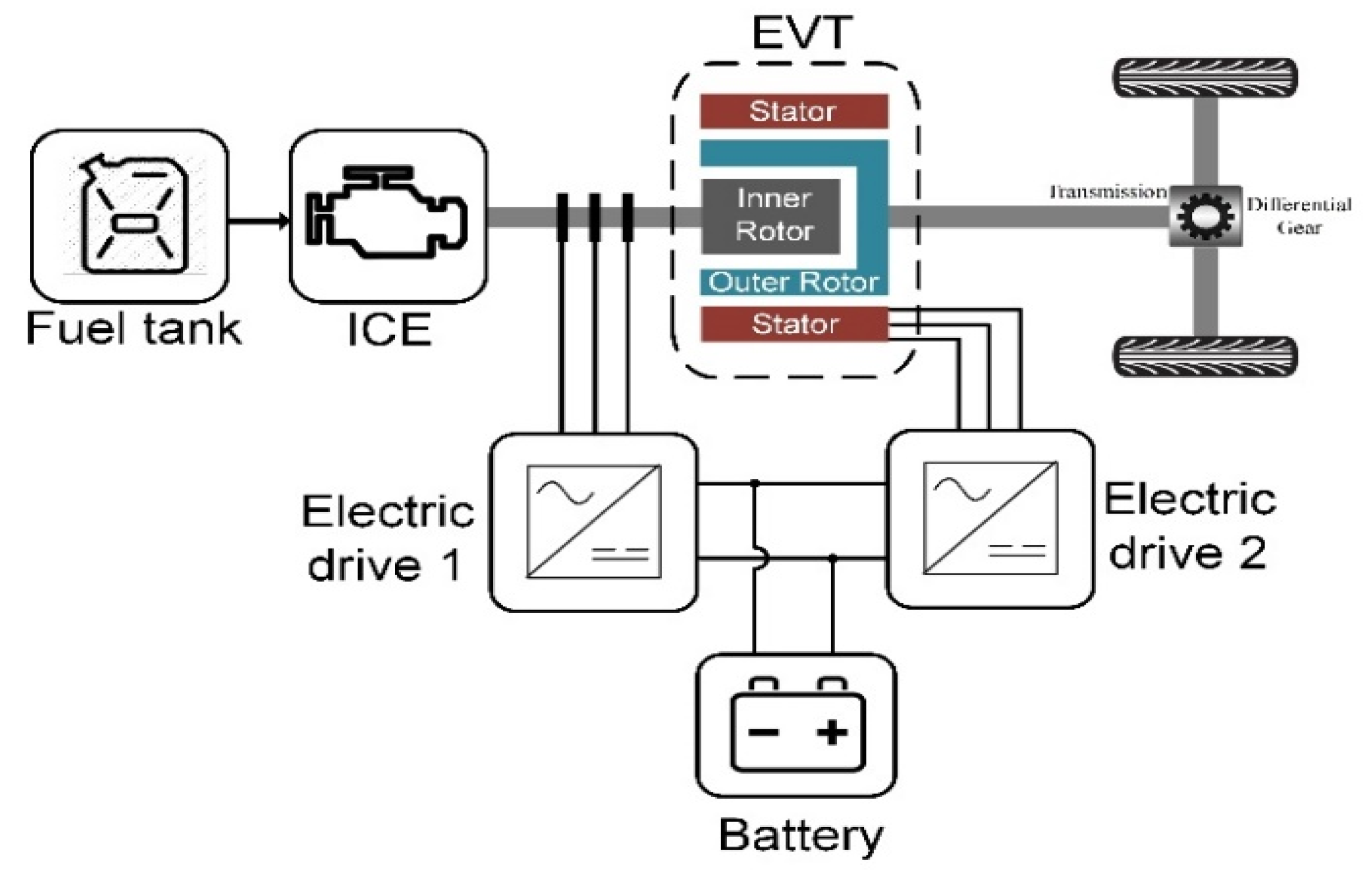
Section 2 presents the EVT-based drivetrain architecture for a passenger HEV. In
Section 3, the individual mathematical modeling of the vehicle components and corresponding descriptions are elaborated.
Section 4 provides the formulation and explanations of the employed EMSs and their incorporation into the model for off-line optimization.
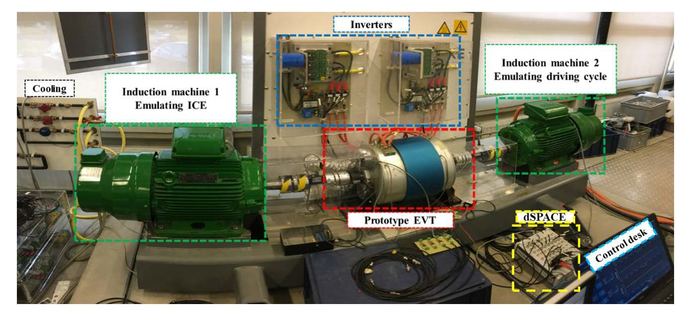
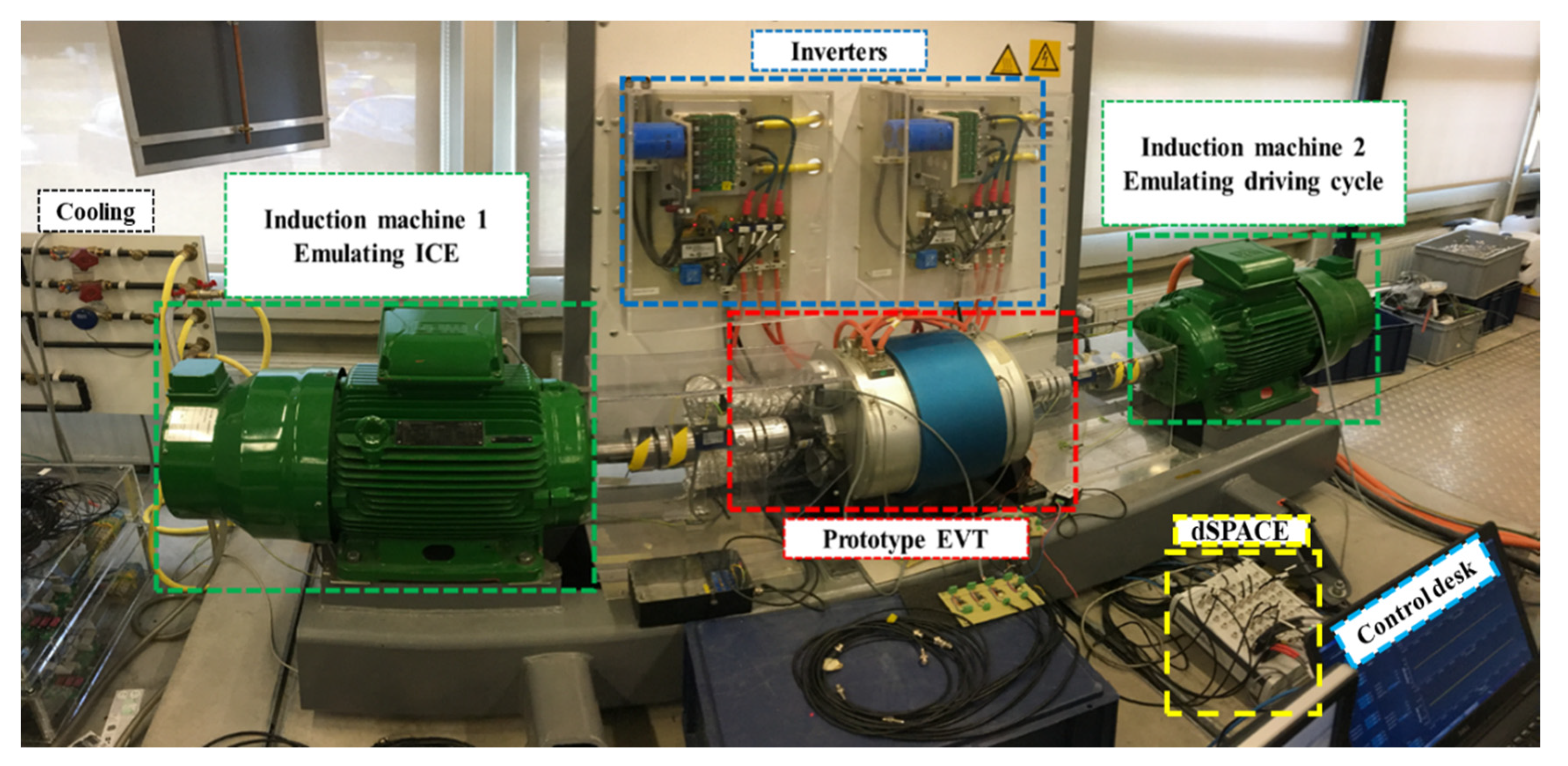
Section 5 presents the specifications of the prepared experimental testbed and its featuring advantages. In
Section 6, the study procedure is provided, and the statistical performance indices required for the agreement and error analyses are briefly expressed.
Section 7 presents and discusses the obtained verification results, and finally,
Section 8 recapitulates the achieved outcomes and provides the conclusions and future work directions.
3. Modeling and Formulation of Vehicle Subsystems
To optimize the EMS, first, it is needed to establish the vehicle’s model before incorporating it in an optimization algorithm. This section goes through the modeling process of the individual components as subsystems of the vehicle model. The MATLAB/Simulink
® version 2016b environment was used to perform the modeling, simulation, and optimization procedures in the present study. Regarding the modeling approach, the backward calculation method was employed since it combines the advantages of simplicity and low computational cost when it comes to integrating the model into the optimization procedure [
37,
48,
49,
50].
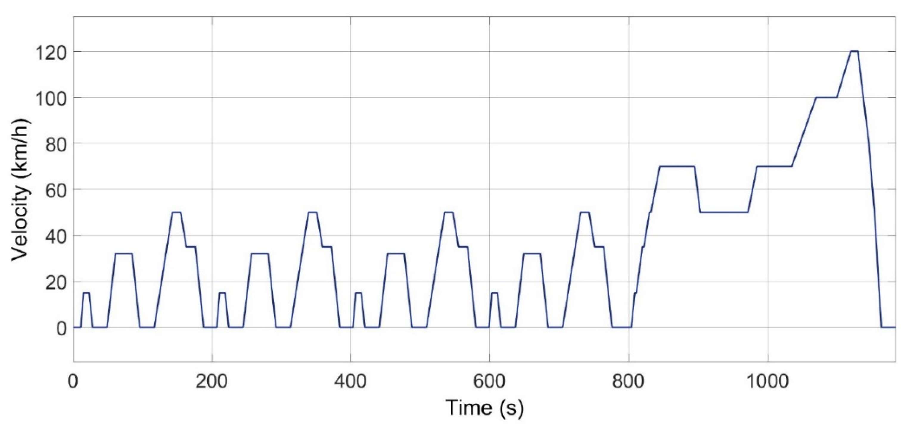
The required speed and acceleration time series besides the vehicle’s constant parameters (
Table 1) are used in the vehicle longitudinal dynamic subsystem to calculate the tractive forces. To this end, this subsystem considers resistance forces corresponding to drag, rolling, gradient, and inertia as follows:
The outputs of the vehicle dynamic subsystem are the wheels’ required torque and rotational speed, which can be readily calculated knowing the wheel’s radius:
An input–output approach using torque–speed pairs based on the efficiency and the fuel rate maps are stored in look-up tables for the ICE subsystem. The non-scaled efficiency map of a generic ICE [
37] was considered for the present study. In the fuel tank subsystem, the consumed fuel (liter) over the driving cycle can be modeled based on Equation (4), where
(g/s) stands for the fuel consumption rate and
ρf (kg/m
3) represents the fuel density.
To model the battery pack, the elements of a first-order Thevenin equivalent circuit as a function of SoC were identified by using the experimental data [
51] and were stored in the Simulink
® look-up tables. The terminal voltage (
Vbatt) and SoC can be mathematically expressed through Equations (5)–(8), where
Voc is the open circuit voltage;
Rint stands for the internal resistance;
Cp and
Rp represent the polarization capacitance and polarization resistance, respectively; and
NBatt stands for the number of the batteries. A LiFePO
4 (LFP) battery type with the specifications given in
Table 2 was considered in this study.
Regarding the power converters, the power–efficiency pairs were stored in their corresponding look-up tables and the power flow directions were considered in the calculations. To this end, for the traction mode (while
p > 0), the efficiency operator
β = −1, and for the braking mode (while
p < 0), the efficiency operator
β = 1 are applied in Equation (9).
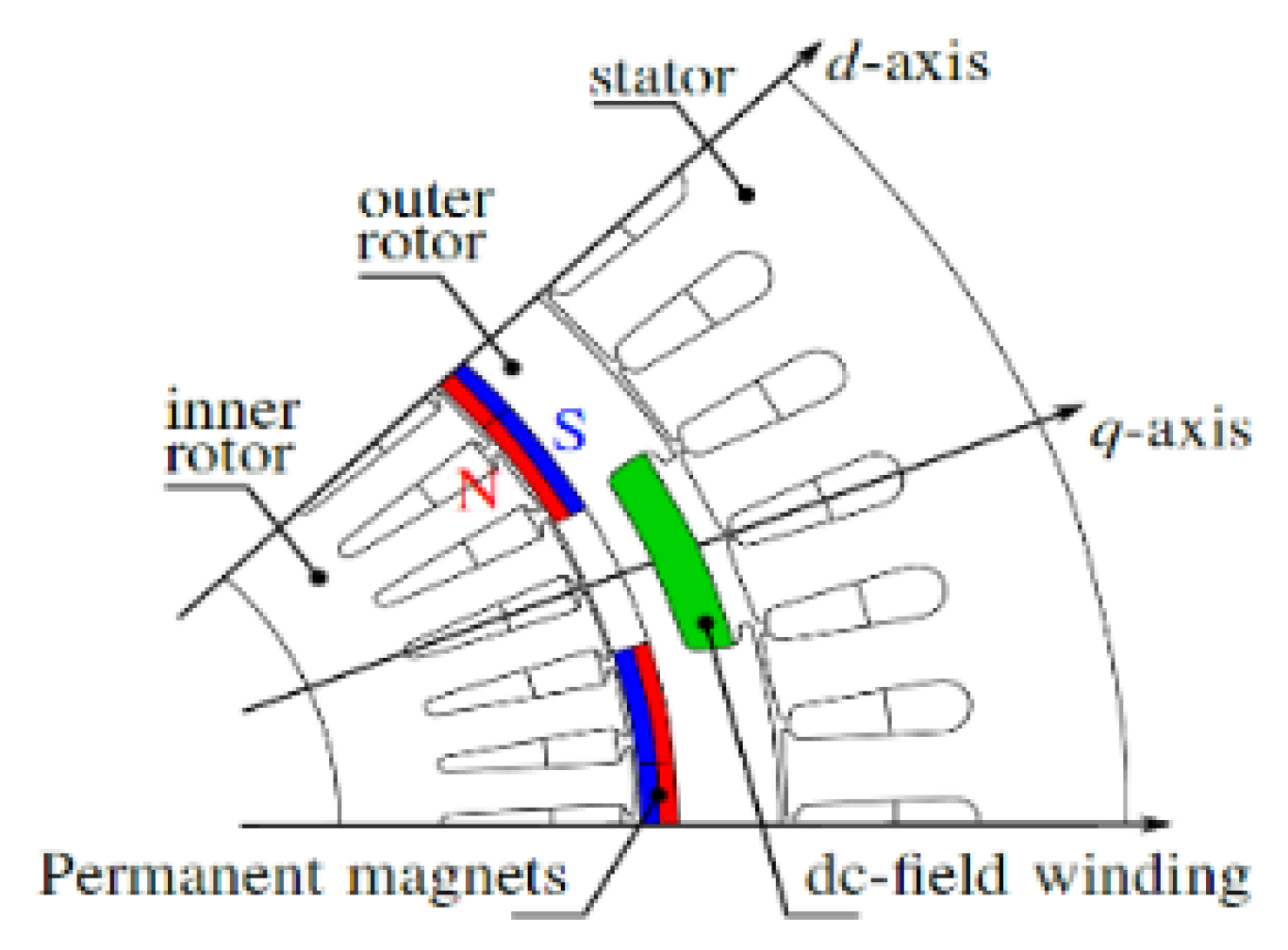
The EVT subsystem consists of two concentric rotors. The inner rotor encompasses a distributed three-phase winding and the outer rotor is equipped with permanent magnets. The EVT subsystem’s inputs are the inner and the outer rotor’s torque and speed. These operating points are considered and a set of five independent currents that minimize iron and copper losses are correspondingly used in different axes (
d and
q). In this regard, as illustrated in
Figure 3, the stator current is in the d and q-axis, the outer rotor’s current is in the d axis, and the inner rotor’s current is in the
d- and
q-axes [
52]. Finite element (FE) calculations validated on a prototype [
53] were used to store the results of the corresponding fluxes (
Ψ) in look-up tables used in the EVT subsystem. Knowing the flux and current, the corresponding torque on each component can be calculated as follows, where
Np is the number of pole pairs and subscripts 1–3 are related to the stator, the outer rotor, and the inner rotor, respectively.
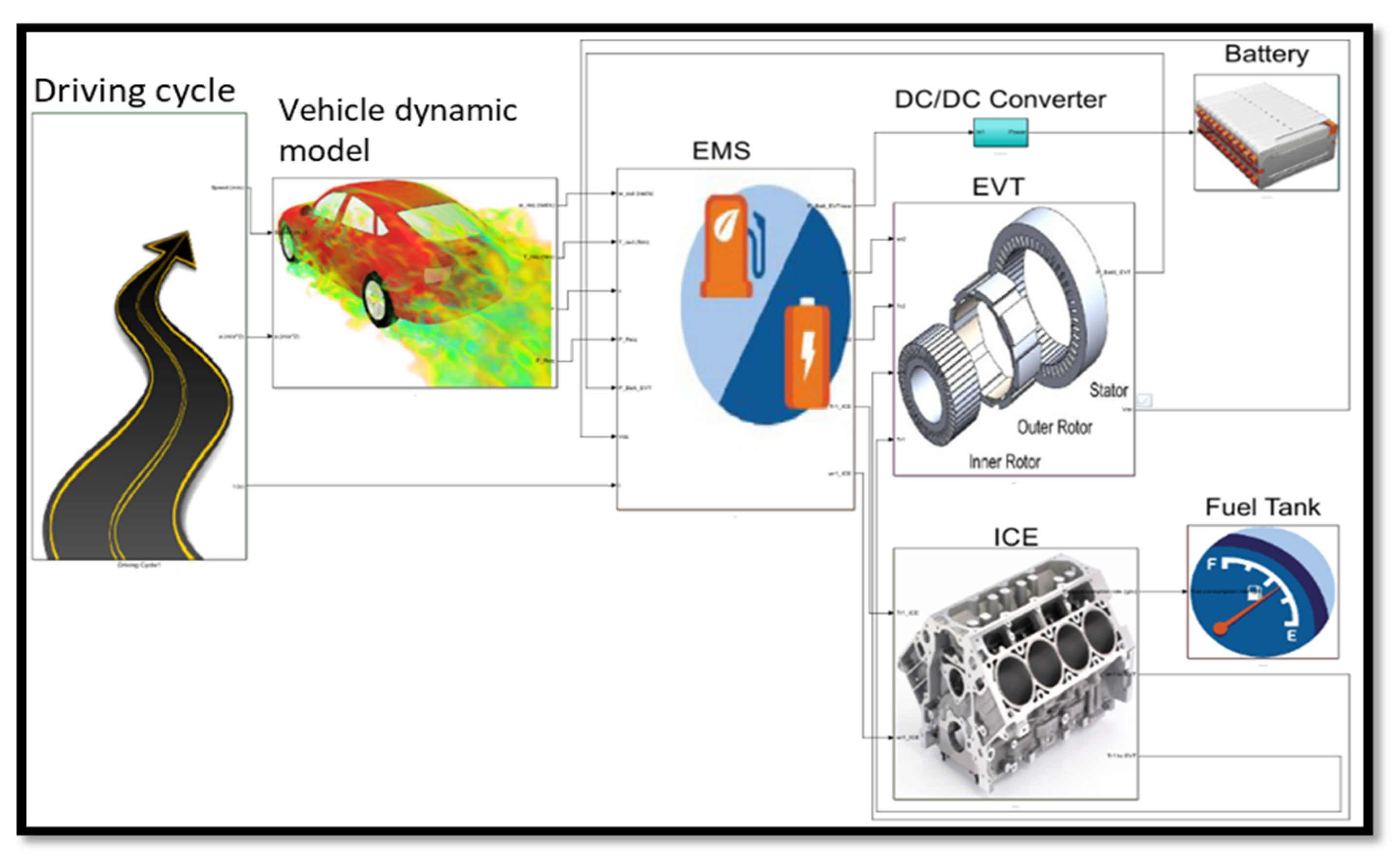
The individual subsystems mathematically explained in the current section were modeled and integrated in a Simulink
® environment to form the whole vehicle model, as illustrated in
Figure 4.
4. Energy Management Strategies
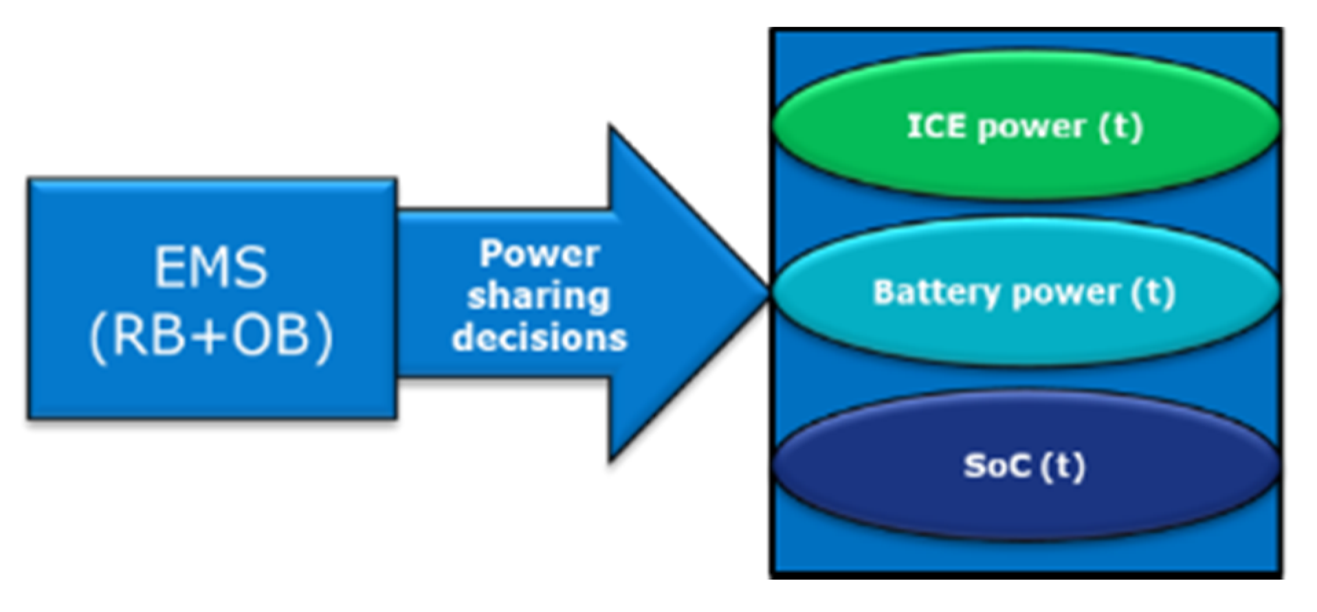
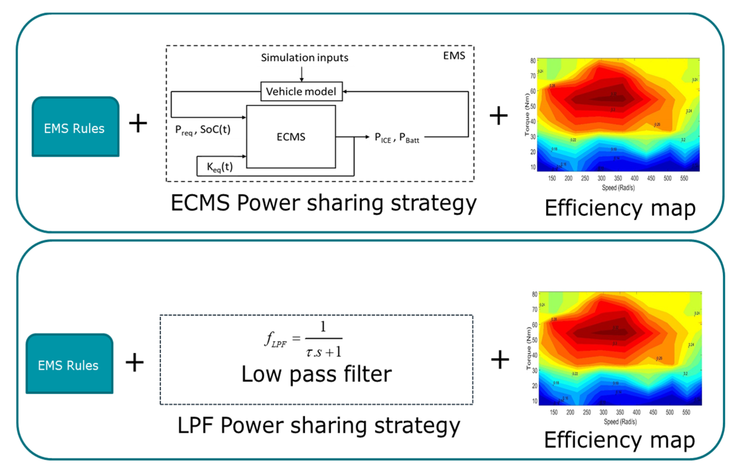
The EMS block, consisting of a rule-based (RB) combined with an optimization-based (OB) approach, is the core of the power sharing control subsystem toward reaching the desired energy management objectives. The main problem of standalone RB strategies is being subjective to predefined perceptions, leading to limited objectives such as battery SoC maintenance being addressed. However, they usually end up to non-optimal solutions regarding objectives such as minimized fuel consumption. Therefore, to provide a robust EMS block, in this study, a RB-based strategy was defined and linked to OB-based strategies such as low pass filter (LPF) and ECMS for power sharing, as illustrated in
Figure 5. The EMS selects operating points and modes to share the requested power between the battery and the ICE and satisfy the control objectives. The EMS must deliver the power in a way that the required driving power is fully satisfied. It operates the ICE by considering its efficiency map and charges the battery provided it is not violating the charging limitations. The SoC needs to be sustained between its intuitively and alterable defined maximum (i.e., 80%) and minimum (i.e., 75%) values, providing initial and final SoC values close enough to each other. All the objectives and their constraints need to be satisfied while minimizing the fuel consumption.
The constraints and objectives considered for the optimization are explained in detail in the ongoing section. To recapitulate the EMS role, the considered goals are illustrated in
Figure 6. The following subsections introduces the employed RB and OB strategies. The effective capability of the used EMSs in handling the goals were proven in previously performed simulation-based studies [
37,
38,
39]. The present study focused on the real-time validation of the proposed strategies by performing HiL experiments in a real-time testbed. Prior to that, the next subsections will review the used RB and OB strategies in more detail.
4.1. Rule-Based Strategy and Operating Modes
The RB strategy considers a set of “If–Then–Else” rules based on driving patterns, SoC, and the conditions of requested versus available power. The set of desired objectives can be well-thought-of while defining these intuition-based control rules. These rules need to be included in the EMS block to work in tandem with the OB power split technique. The EMS must provide a flexible operation of the ICE in efficient operating points to meet the requested driving demands and satisfy the charging requirements. To this end, by using a speed–torque–efficiency look-up table, the EMS subsystem rules link the instantaneous split torque to its corresponding speed, leading to the highest efficiency on the engine map. The rules update the operating modes by considering the status of the demanded loads, required speeds, available energy from sources, and SoC values. The considered modes are categorized as follows.
If the requested power is greater than the available power by the ICE, it needs to be supplied in a “hybrid-traction” mode in which the required traction power will be supplied by the ICE assisted by the power drawn from the battery.
There is an opportunity to charge the battery by a part of the ICE power, if the total requested power is lower than the available ICE power. In this condition, the vehicle works in “engine-traction and battery-charging” mode in which the ICE partially supplies the requested traction power while its remaining part will charge the battery to maintain the SoC, considering its allowable minimum and maximum window range.
In the “battery-only” mode, a threshold of requested speed will be considered to turn off the ICE, and the battery pack supplies all the requested power, seeing that the battery SoC does not violate its minimum allowable value (i.e., predefined by the rules).
While braking, the battery charge can be sustained either in “hybrid battery-charging mode” or “regenerative-braking mode”, satisfying the maximum allowable SoC value. In the “hybrid battery-charging” mode, the battery is charged using the energy delivered by the ICE, aside from the energy that is partially recuperated from braking. However, in the “regenerative-braking” mode, the ICE is turned off and only the kinetic energy of braking is converted to its electrical form to supply the battery.
4.2. Low Pass Filter Power Sharing Strategy
The performance and the fuel economy of HEVs are crucial, depending on the employed power splitting methods. Hence, the utilization of a proper power splitting method in the EMS subsystem lies in the concept of power sharing between the resources toward improving the efficiency and control robustness. In this regard, an optimized low pass filter (LPF) strategy can be used by finding the proper decisive power sharing control variable (i.e., τ). The utilization of a LPF is decided on the sharing power between the supplying sources to satisfy the requested power. It uses a transfer function and filters out the input elements and passes the output ones. To supply the demanded power, the filtered component of the power passes to be supplied by the ICE, while its difference with the total demand is supplied by the battery, taking the downstream losses into account. One should consider that the output power being delivered by the ICE needs to have enough slow variations to avoid experiencing sudden operation changes, providing an achievable actuation response. This adds to the importance of needing feasibility verifications through a HiL testbed emulating the ICE.
In the present study, a standard transfer function for the LPF was used in the energy management subsystem as follows:
where the control variable
τ is the LPF denominator and plays the decisive power sharing role. The proper value for this control variable can be searched through an optimization routine to have the control objectives satisfied.
4.3. Equivalent Consumption Minimization Strategy (ECMS)
ECMS is a control strategy to search for an optimal power split between the ICE and battery while satisfying several equality and inequality constraints and control objectives such as SoC maintenance and fuel consumption minimization. It works based on equivalence fuel consumption factors derived as a feedback of instantaneous SoC-based functions grounded on Hamiltonian optimal control theory and Pontryagin’s minimum principle [
54,
55,
56,
57].
In ECMS, the main objective is to minimize the overall fuel consumption rate, which comprises the ICE fuel mass flow rate
, plus the equivalent fuel rates of electricity
being calculated by the equivalence factors.
For calculation of the equivalent fuel drawn from/supplied to the battery, the equivalence factors play an important role since they directly affect the power split and consequently the fuel consumption. Optimal power sharing relies on finding the factors leading to a minimized fuel consumption. The equivalence factor
Keqf can be instantaneously used as a control feedback, which is a function of SoC for optimal power split and battery charge maintenance [
24]. This can be expressed mathematically based on [
21,
58] for the formulation of the ECMS-based strategy as follows:
where
QLHV represents the fuel lower heating value and
η is the total drivetrain chain efficiency of the downstream components included in the backward modeling. Acting as the equivalence coefficient factor,
Keqf is the conversion weight of the electricity into fuel.
PP and
PI are the gain multipliers controlling the stiffness and deviation of
SoC around the nominal average of minimum and maximum values. Along this line, the ECMS provides instantaneous power sharing between ICE and the battery considering predefined
SoCmin and
SoCmax values, current SoC values
SoC(
t), time step Δ
t, and feedback gain multiplier
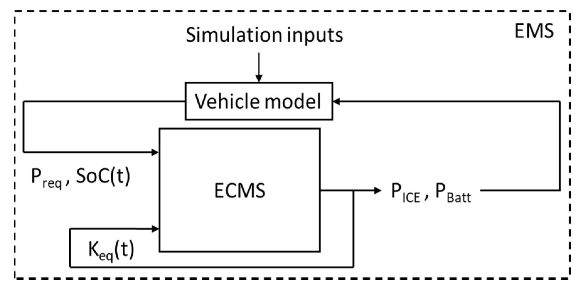
μ as the fine-tune decision variable. To this end, ECMS updates the instantaneous equivalence factors by way of counteracting SoC deviations to maintain the SoC proportionally when it is reaching its maximum/minimum allowable values, supporting discharging/charging the battery, respectively.
Figure 7 illustrates a simplified flowchart of input and output for the ECMS states.
4.4. Incorporation of the Optimization Algorithm to the Model
In this study, the decisive control parameters of the EMS cases,
μ for the LPF, and τ for the ECMS, were introduced into a genetic algorithm (GA) scripted in MATLAB, which is incorporated into the Simulink-based vehicle model. The widely used GA works are based on the evolutionary process concept of natural selection in Darwin’s theory. This theory proposes that only the fittest populations can produce offspring through natural selection and survival, while unsuitable populations will be eliminated. The same concept can be conducted into mathematical optimizations where during processes like crossover, mutation, and natural selection, the good design points can be selected while neglecting worse answers toward finding optimization solutions for objective functions (survival of the fittest) [
59]. The desired constraints can be defined separately or be integrated into the objective functions as penalties [
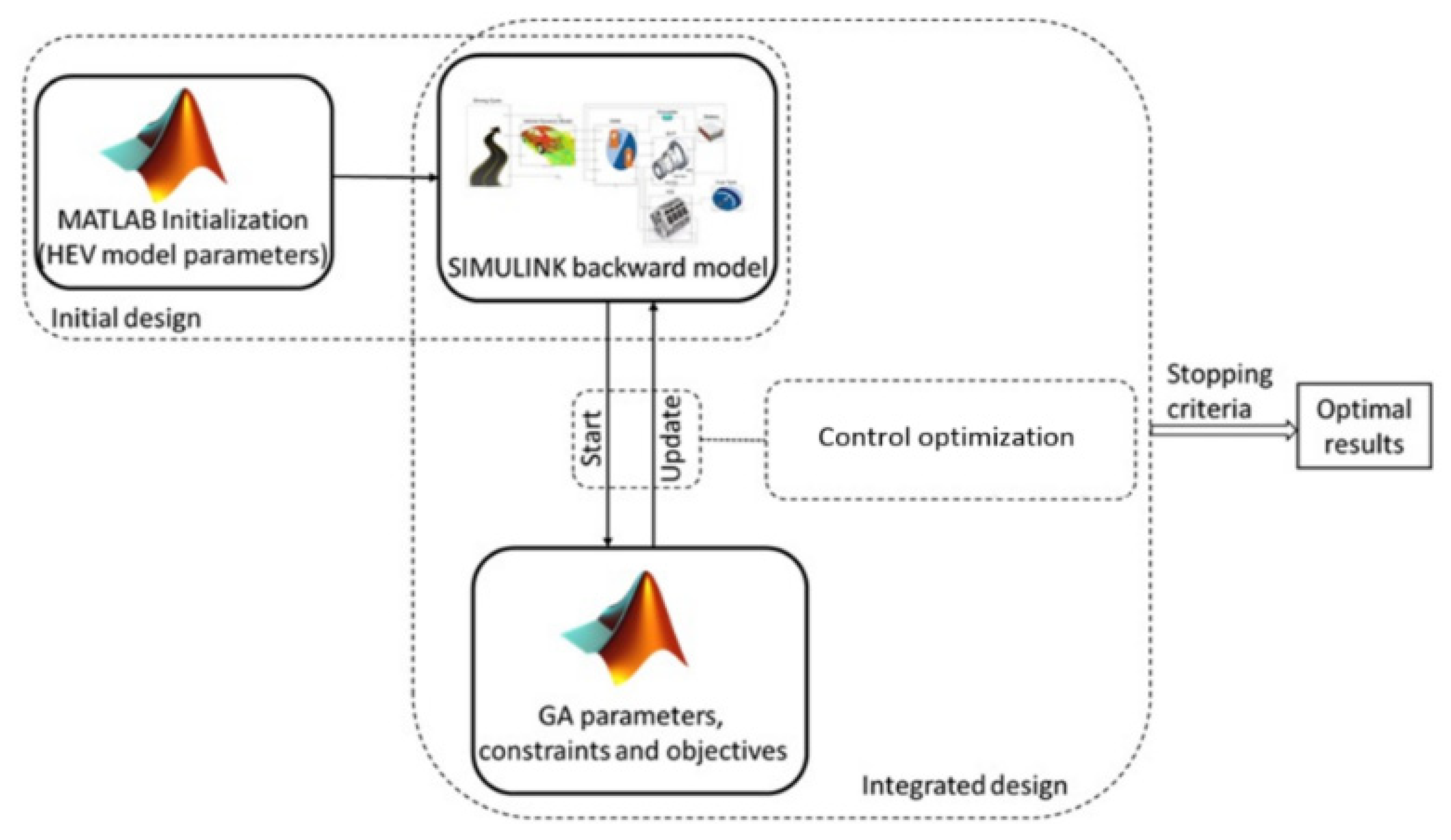
16]. In the present study, the optimization algorithm and the vehicle model worked iteratively in tandem to update each other for the optimization procedure. The GA considers the decision variables as input chromosomes aside from the defined minimum and maximum values of the constraints to minimize the fuel consumption and satisfy the EMS constraints as follows.
Two sets of SoC constraints were considered here where the first one, based on Equation (23), represents the charge-maintenance requirement in HEVs. The second SoC constraint, based on Equation (24), expresses the allowable minimum and maximum limits of the SoC considered for the optimization through the driving cycle. Regarding the first mentioned inequality, the typical charge-maintaining equality SoCf = SoCi was used to define the inequality constraint (23). Hence, ΔSoC, as the difference between the initial and final SoC values would need to stay within a small enough feasible bound ε0 in the optimization process. It is remarkable that this constraint can be hardened/softened via altering ε0. Furthermore, to avoid sudden charges and to prevent fast aging of the battery pack, the EMS must consider the limitation of the battery. In this regard, the constraint, based on Equation (25), of the provided features of the battery chemistry was considered where β = −3.
For the explained constraints, they were incorporated into the optimization process as penalties panelizing the objective function by adding a big enough penalty value when a desired constraint is violated. This method is a practical method to consider the constraints that cannot directly be included in the optimization formulations. The interrelations of the described modeling and optimization process are illustrated in
Figure 8.
7. Results and Discussion
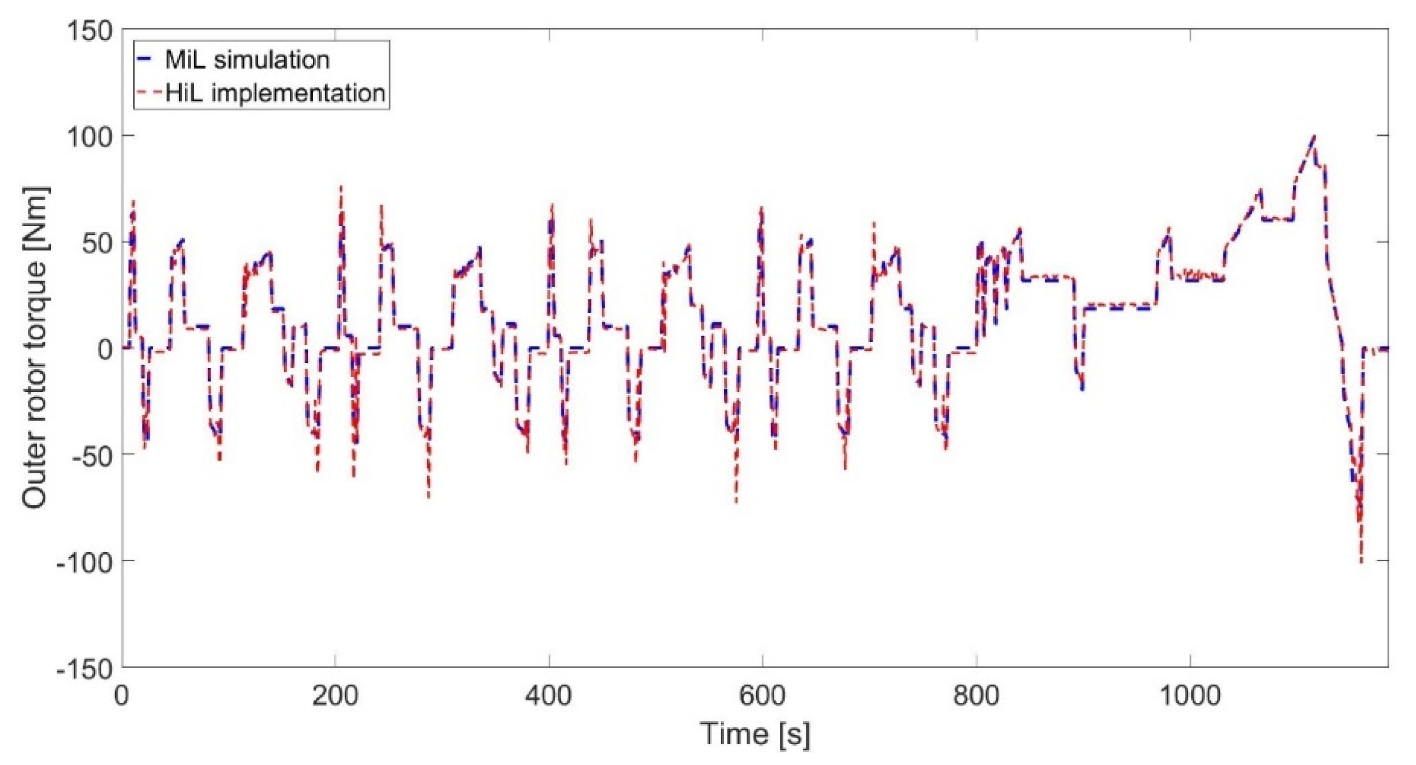
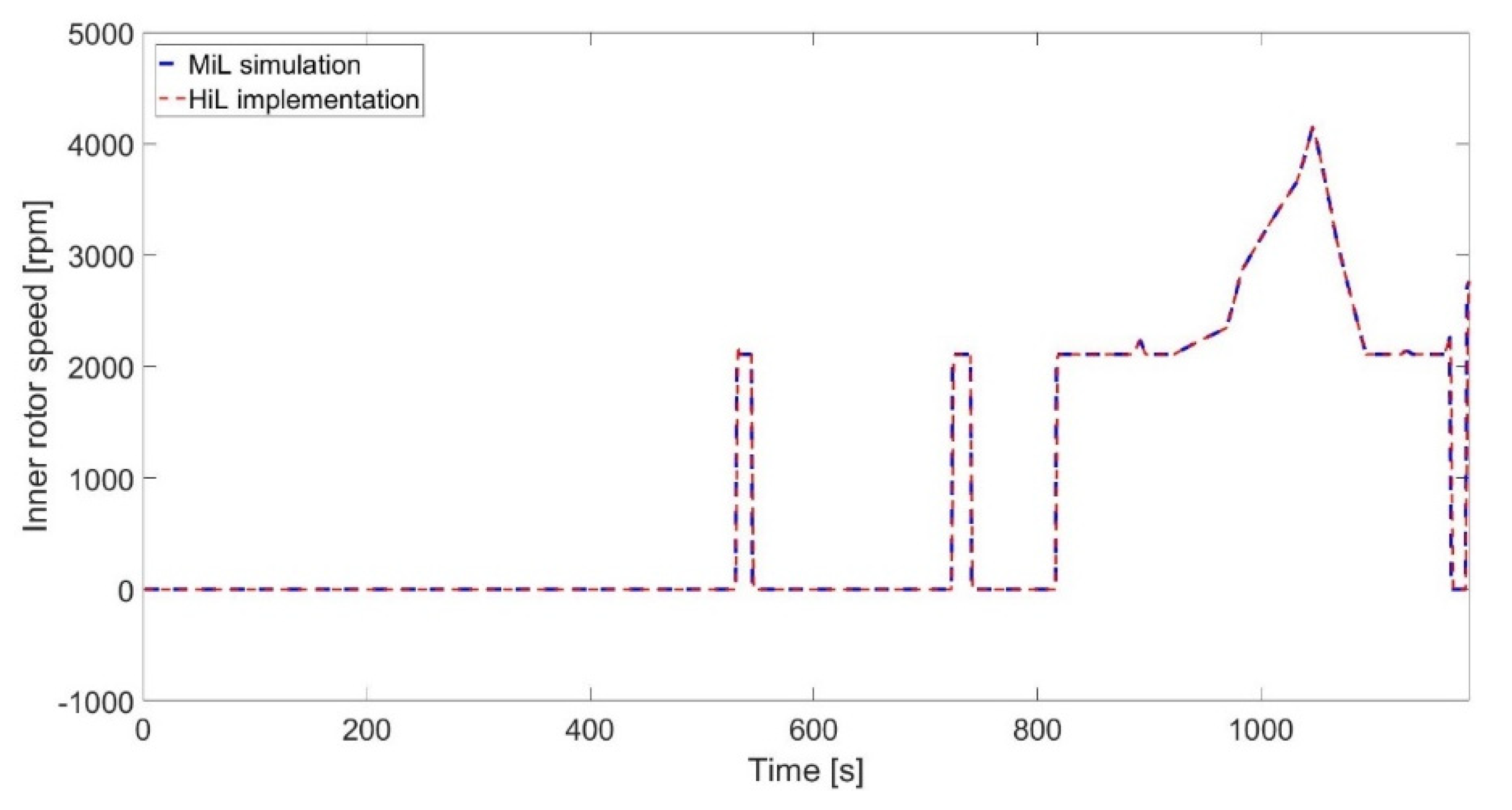
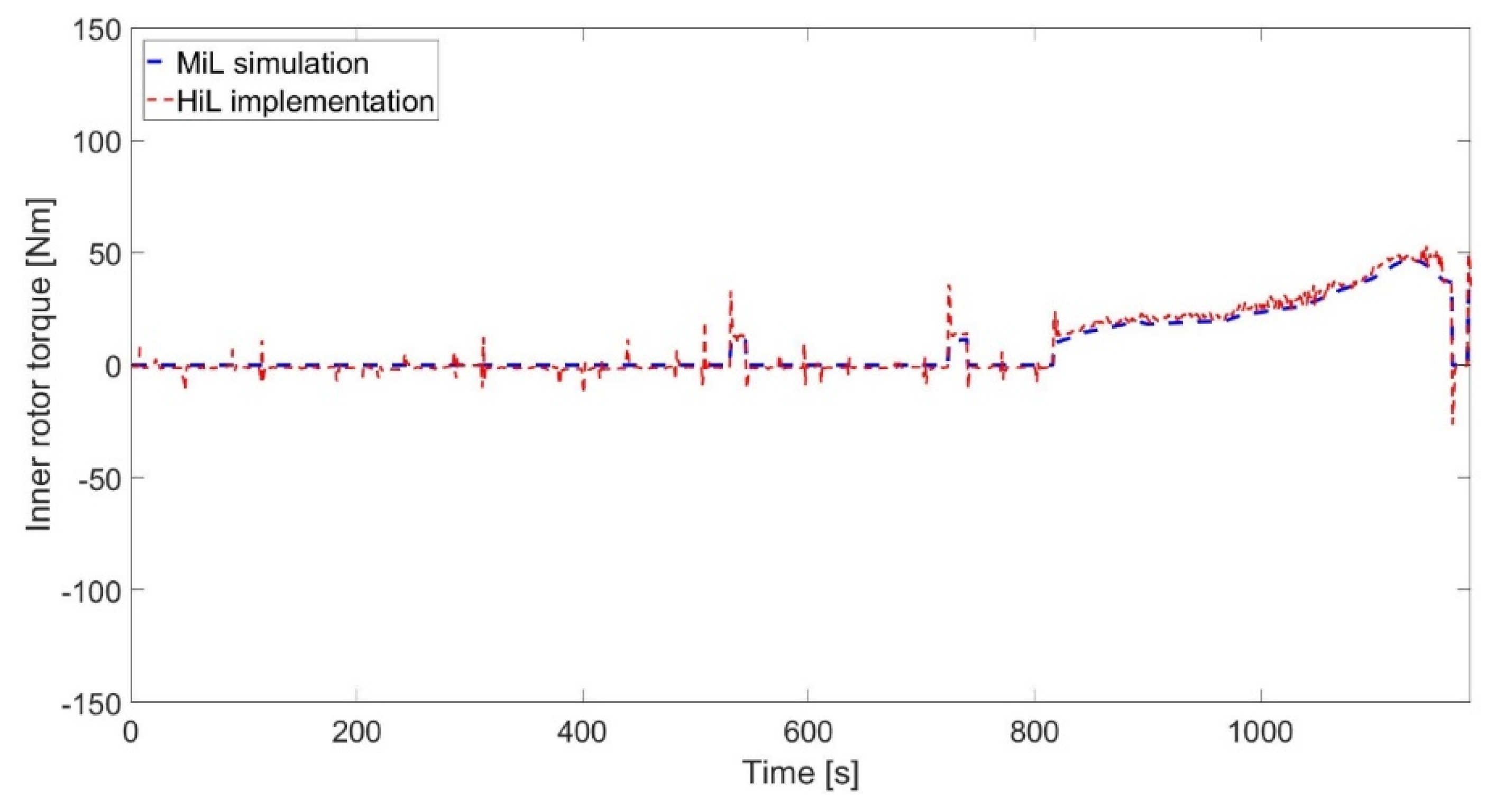
After performing the HiL implementations over the NEDC, real-time results for the inner and outer rotor actuations including the torque and speed dataset were achieved and stored. These results were compared with the corresponding ones acquired from the MiL simulations. The MiL vs. HiL results were plotted to observe the response performances and agreement accuracies for the studied cases. Accordingly, the statistical performance indices were applied over those dataset pairs, and calculated results are provided for long-term verification as follows.
For the LPF-based EMS case,
Figure 15 illustrates the results of the outer rotor torques. The speed results for the same rotor are plotted in
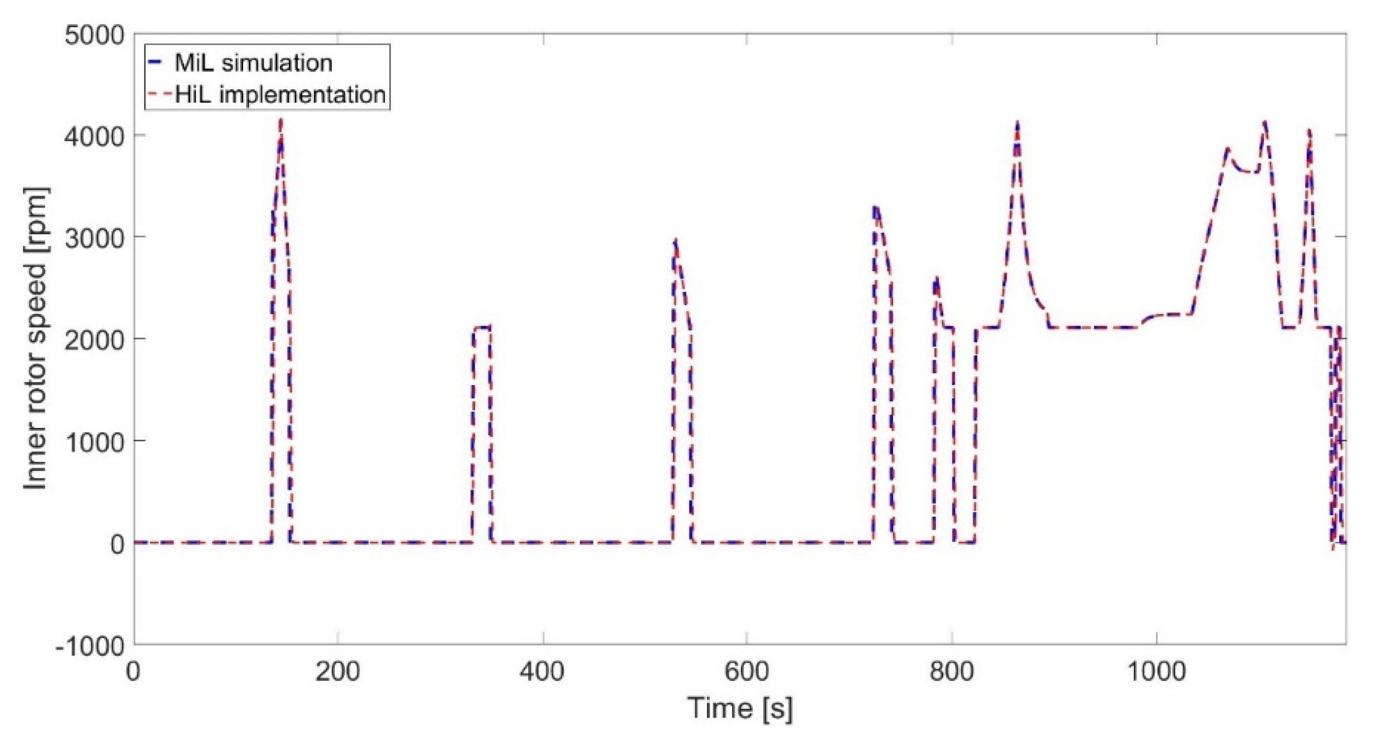
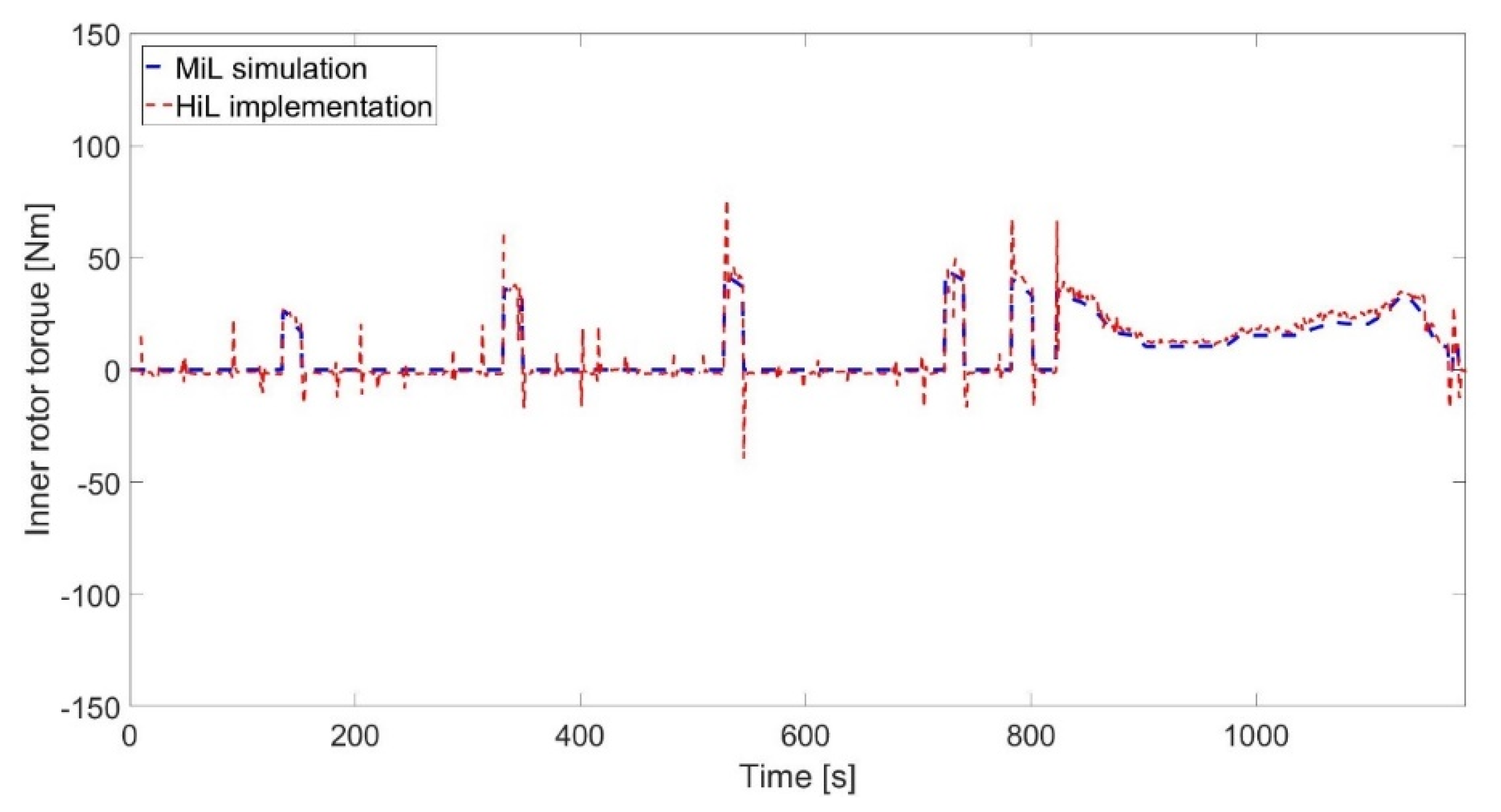
Figure 16. With regard to the inner rotor, the achieved speed and torque results of the same case are presented in
Figure 17 and
Figure 18, respectively.
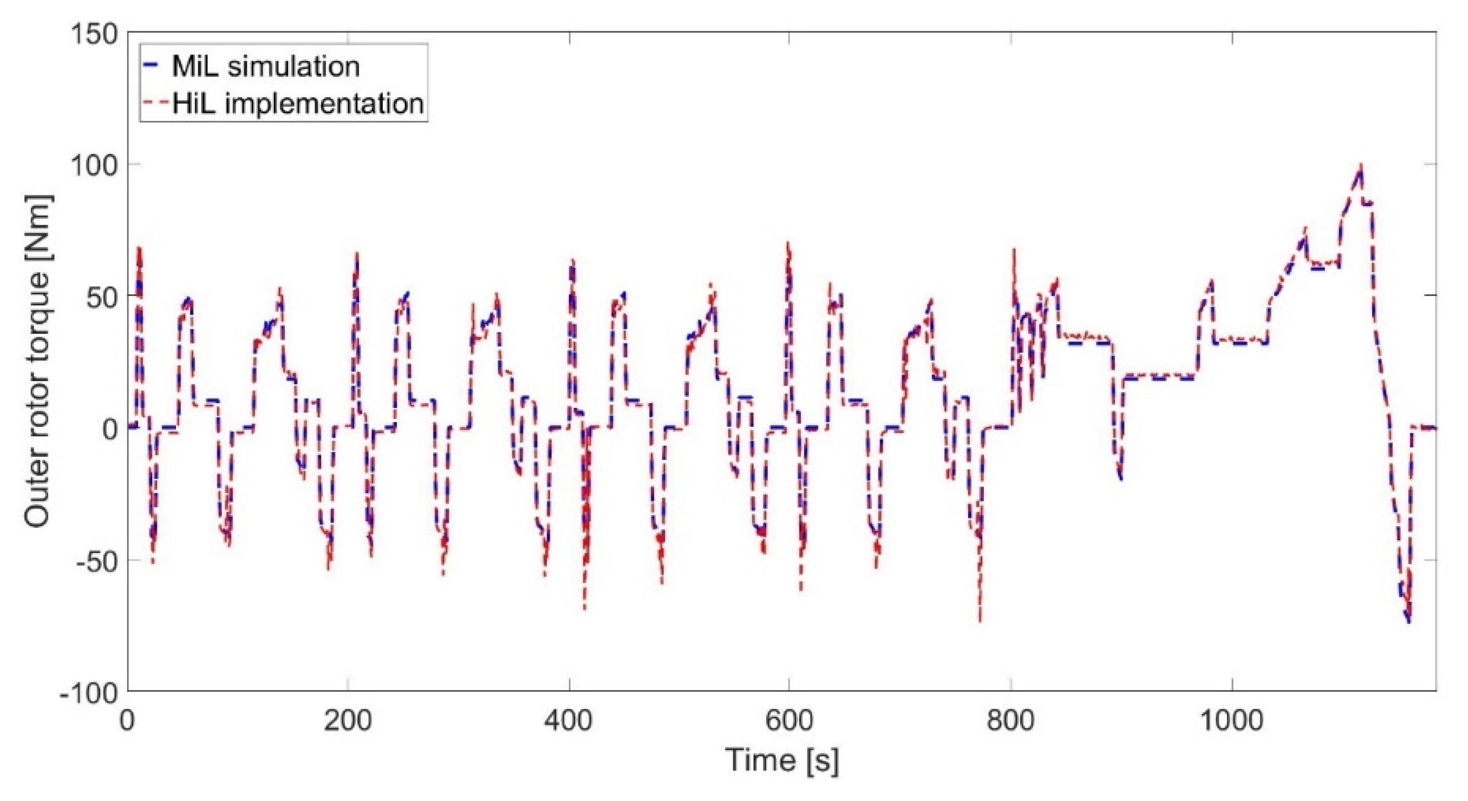
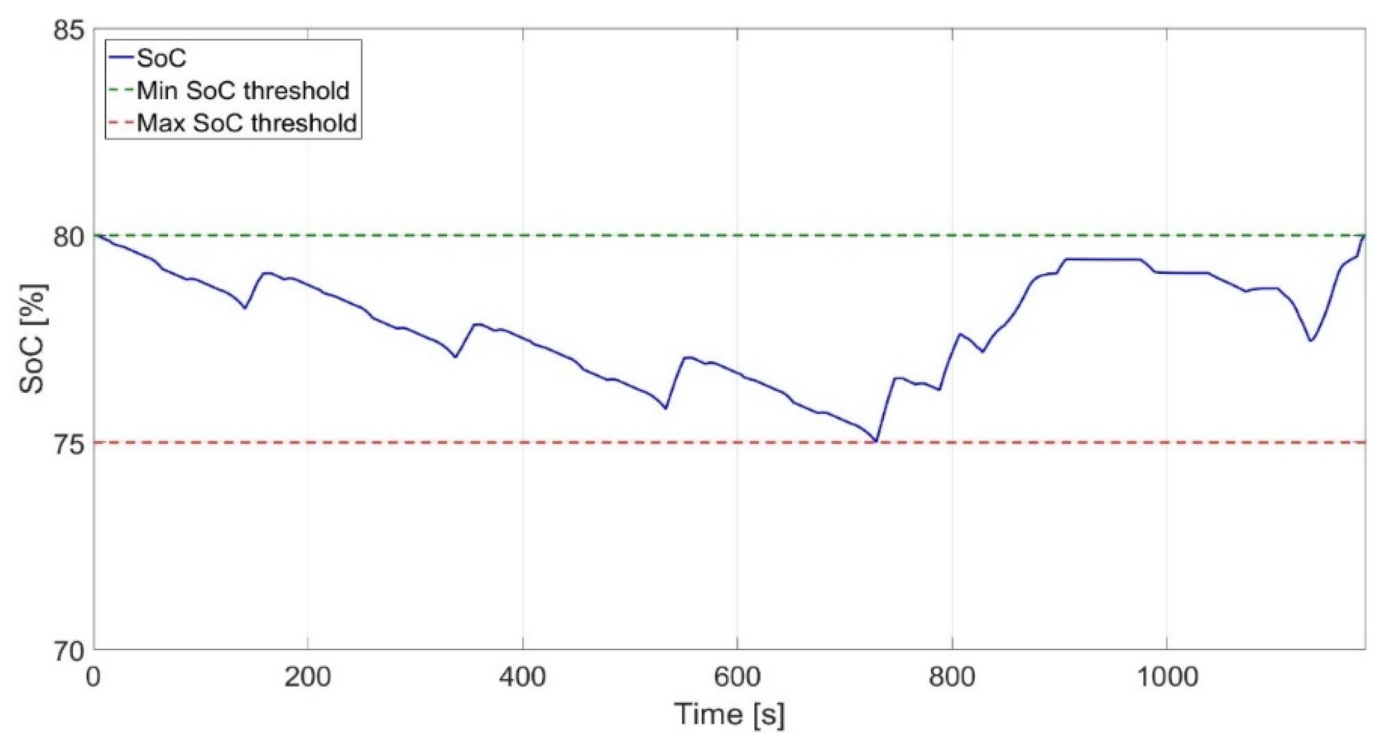
Figure 19 illustrates the obtained SoC for this case. For the ECMS-based case study,
Figure 20 illustrates the results for the outer rotor torques, while the speed results for the same rotor are plotted in
Figure 21. Consequently, the speed and torque results of the inner rotor for this case are presented in
Figure 22 and
Figure 23, respectively.
Figure 24 illustrates the obtained SoC for this case. Considering
Figure 15,
Figure 16,
Figure 17 and
Figure 18,
Figure 20,
Figure 21,
Figure 22 and
Figure 23, an investigation of the results through the cycle indicates that the actual torque and speed values obtained from the HiL implementations could closely follow the MiL simulations with well-matched responses for both of the studied EMSs. Along the same line,
Figure 25 provides the error histogram for the investigated MiL vs. HiL occurrences where normal distributions around zero error values were favorably observed. The allowable SoC range considered 75% for the minimum and 80% for the maximum thresholds. As can be seen in
Figure 19 and
Figure 24, both employed strategies could well-maintain the SoC by achieving close enough initial and final values as desired. Regarding the MiL vs. HiL results, some inevitable mismatches related to noises were observed. These inevitable deviations could be expected, as has also been widely observed in the results of similar studies performed previously such as in [
8,
25,
26,
62]. This can be interpreted as mismeasurements imposed on the sensors by the laboratory’s environmental conditions, machine vibrations, or abrupt accelerations of the induction machines. Regarding the minor noises, they can be more readily recognized where the measured HiL data exhibited values slightly greater/smaller than zero whereas the MiL dataset appropriately followed zero values for the same instants. From what was physically observed in the lab through multiple similar examinations, there were no rotational actuations for those moments in the HiL tests, making them indeed comply with the MiL results. Hence, for the mismeasurements, it can be seen that vibrations coming from a rotating rotor (e.g., outer) would slightly affect the measuring quality of a standstill rotor’s sensor (e.g., inner). Furthermore, noises from the lab environment, the testing conditions, and the air quality (e.g., dust, temperature, humidity, etc.) might cause these types of inevitable noises to be recorded. On the other hand, other mismatches were observed where the actuations started undertaking great changes. As expected, when sudden accelerations were imposed by either of the two induction machines (e.g., see
Figure 15, t = 200 s), the measuring quality was affected by exhibiting an overshoot for a short instant (inertia effect).
For a precise performance evaluation, long-term statistical analyses of the obtained results considering the whole cycle is necessary. Hence, the previously introduced statistical performance indices were applied over the obtained MiL vs. HiL results and the calculation outcomes for the studied cases are provided in
Table 5 and
Table 6. Although the discussed measuring mismatches were seen in the calculations, quite favorable values were achieved for RMSE and MSE (both close to 0) and R
2 (close to 1), knowing the minimum and maximum ranges of the compared datasets. This indicates the fast and accurate response capability of the tested EMSs in such a real-time application and was validated using the prepared test bench. The versatile testbed provided for the studied topology can be used for similar studies to test the applicability of other combined/standalone EMS types and validate their HiL vs. MiL/SiL results, paving the way toward vehicle-in-the-loop experiments.

 ,
, 


