Article

Biomechanical Evaluation of Initial Stability of a Root Analogue Implant Design with Drilling Protocol: A 3D Finite Element Analysis

1
Department of Prosthodontics, Korea University An-san Hospital, Gyung-gi do 15355, Korea
2
Department of Biomedical Engineering, College of Medicine, Seoul National University, Seoul 03080, Korea
3
Department of Advanced Prosthodontics, Graduate School of Clinical Dentistry, Korea University, Seoul 02841, Korea
4
3D Printer Team, Dentium Co., Ltd., Gyung-gi do 16229, Korea
5
Department of Prosthodontics, College of Dentistry, Yonsei University, Seoul 03722, Korea
6
Department of Periodontics, School of Dentistry, Seoul National University, Seoul 03080, Korea
7
Department of Prosthodontics Korea University Anam Hospital, Seoul 02841, Korea
8
Institute for Clinical Dental Research, Korea University, Seoul 02841, Korea
*
Author to whom correspondence should be addressed.
These authors contributed equally to this work.
Appl. Sci. 2020, 10(12), 4104; https://doi.org/10.3390/app10124104
Submission received: 8 May 2020 / Revised: 12 June 2020 / Accepted: 13 June 2020 / Published: 15 June 2020
(This article belongs to the Special Issue Computer Simulation Modelling in Sport)

Abstract

:
Background: The aim of this study was to biomechanically evaluate the initial stability of a patient-specific root analogue implant (RAI) design with drilling protocol by comparing it to designs without drilling protocol through a 3D finite element analysis (FEA). Methods: A 3D surface model of an RAI for the upper right incisor was constructed. To evaluate the effect of root apex drilling, four modified RAI shapes were designed with the press-fit implantation method: Non-modified, wedge added at root surface, lattice added at root surface, and apex-anchor added at root apex (AA). Each model was subjected to an oblique load of 100 N. To simulate the initial stability of implantation, contact conditions at the implant–bone interface were set to allow for the sliding phenomenon with low friction (frictional coefficient 0.1–0.5). Analysis was performed to evaluate micro-displacements of the implants and peak stress on the surrounding bones. Results: Under all low frictional coefficient conditions, the lowest von Mises stress level on the cortical bone and fewest micro-displacements of the implant were observed in the AA design. Conclusion: In view of these results, the AA design proved superior in reducing the stress concentration on the supporting cortical bone and the micro-displacement of RAI.

1. Introduction

Osseo-integrated dental implant systems and the surgical techniques for the replacement of missing teeth have improved continuously and represents a highly predictable therapy over the past few years [1,2,3]. Although scientific advances in the field of dental implants have been quietly consolidated, the reduction of invasive surgery and rehabilitation time, as well as patient demand for esthetics, especially in the maxillary in the maxillary anterior zone, still pose significant challenges for dentists [4]. However, there is no general consensus for the optimal design for an immediately placed implant in the maxillary anterior esthetic zone [5]. According to the previous anatomical studies it is suggested that the immediate placement position of a conventional screw type implant should be palatal side with the tooth extraction in order to maintain significant primary stability and avoid thin alveolar maxilla [6]. From the mechanical viewpoint, this is reasonable because of the larger lateral component of the occlusal force and the smallest implant–bone contact area. Therefore, the root-analogue implants, press-fit implants inserted immediately after extraction, that can obtain friction force from all contact areas of the tooth extraction socket after immediate implantation, have raised great attention among the researchers and dentists [7,8,9,10,11].
The concept of immediately replacing missing teeth with patient-specific root form implants has long been in place, with many laboratory experiments and clinic trials using root analogue implants (RAIs) [8,9,12]. However, due to initial instability and high failure rates over short follow-up periods, patient-specific implant systems are still considered experimental and not yet recommended for clinical use [12,13]. With the recent rapid development of computer-aided design and computer-aided manufacturing (CAD/CAM) technology, the design of patient-specific RAIs has been reconsidered to resolve the discrepancy between the cylindrical-shaped conventional implant and an individual’s tooth-extraction socket [7,9,10,14,15].
Conventional screw-type implants achieve initial stability through mechanical fixation by implant threads in the bone [16]. However, initial stability of the RAI is based on the press-fit phenomenon [7,17,18]. Since patient-specific RAIs are based on cone beam computed tomography (CBCT), CAD, and 3D printing technology, unlimited modified RAI designs are available. According to previous studies, most RAI design options, aimed at increasing the initial stability of the RAI, are created to achieve initial mechanical fixation by varying the surface shape of the RAI root without additional drilling protocol [19,20].
Finite element analysis (FEA) has become an effective method to evaluate peri-implant bone stresses and the relative micro-displacement between bone-to-implant interfaces under certain loading conditions [21]. However, most previous FEA studies on RAIs were limited in the analysis of the initial stability, which is one of the most important factors for the success of implant placement; they assumed the contact condition between the bone and implant was fully bonded and in a completely osseo-integrated state [19,22].
Thus, in this study, we aimed to evaluate the initial stability of a modified RAI design with additional mechanical fixation through anchorage at an additional drilling site at the root apex through comparison with several RAI designs that only modify the root surface shape without additional drilling protocol. To analyze the initial stability immediately after implant placement, the contact conditions between the bone and implant were set with a low friction coefficient (0.1 to 0.5), allowing for a sliding motion to mimic incomplete osseo-integrated conditions in the 3D FEA.

2. Materials and Methods

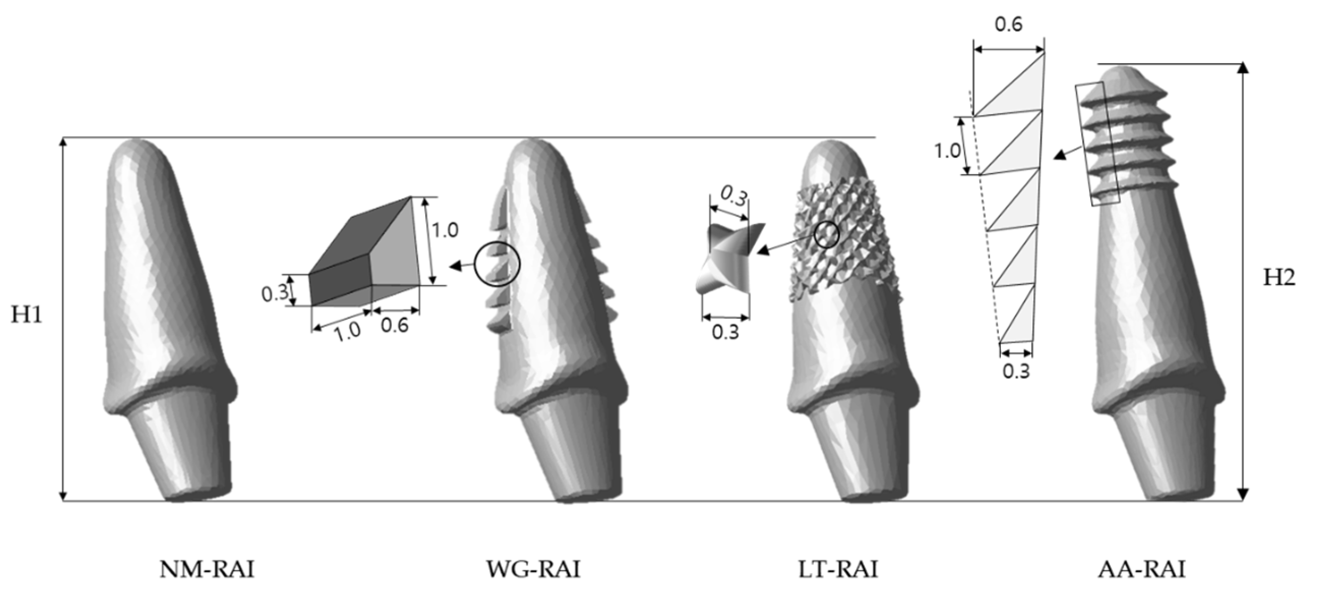
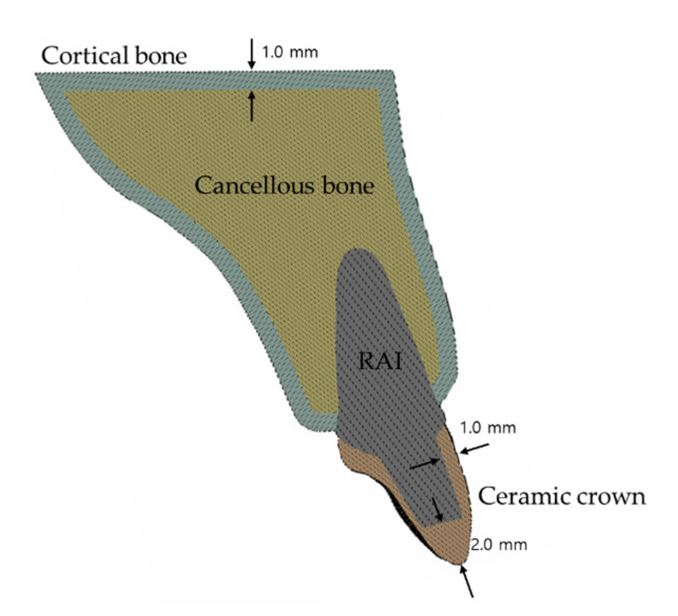
2.1. Three-Dimensional Model Design

This study was performed under approval of the Institutional Review Board of Korea University Medical Center (KUMC) (IRB no. MD13022). A randomly selected maxillary central incisor from the human tooth bank at the KUMC dental center was used to build the tooth model. The geometry of the tooth was obtained through optical scanning with an i500® intra-oral scanner (Medit Inc., Seongbuk-gu, Seoul, Korea) and 3D modelling with CAD software from Geomagic Wrap® (3D Systems Inc., Cary, NC, USA).
Based on the obtained stereolithography model of the maxillary incisor, four different RAI FE models were constructed using 3D CAD software (Inventor, Autodesk GmbH, Munich, Germany). For the four RAI models, a standard identical abutment was created based on morphological expectation of the original tooth crown. Among the four RAI designs, the following three design modifications at the root surface were constructed to allow for no additional drilling: (1) Non-modified root surface (NM); (2) wedge shape added at mesial and distal root surface (WG); and (3) lattice shape added at root surface (LT). The fourth RAI design has anchorage in the root apex, implanted using the press-fit method after additional drilling in the root apex area: (4) apex-anchor added RAI (AA). Figure 1 shows the four RAI designs with descriptions of the different geometrical characteristics.
The geometry of the tooth-supporting maxillary bone with 1.0 mm thick cortical bone was constructed in accordance with a previous study [23]. In the 3D geometry maxillary alveolar bone model, an empty socket after a tooth extraction was formed by subtracting with the root part of each RAI model made by modifying the original tooth shape for each experimental group. The outer geometry of the ceramic crown component is the same as that of the crown of scanned tooth. The inner socket of the ceramic crown was formed by subtracting the RAI abutment part with arbitrary designed but having the same shape in all experimental groups. The thickness of ceramic crown is 0.5 mm at the lingual side, 1.0 mm at the labial side, and 2.0 mm at the incisal side. Figure 2 shows a 2D sectional view of the experimental group NM to explain the mutual relationship with the components constituting one experimental group. Figure 3 is a 3D diagram depicting the components of each experimental group.

2.2. Material Properties, Loading Conditions, and Constraints

All materials used to construct the models were assumed to be isotropic, homogeneous, and linearly elastic. The mechanical properties of all materials used in this study were taken from a previous study [24] (Table 1).

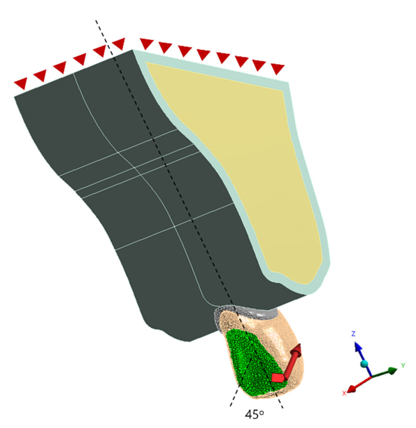
2.3. Boundary Conditions and Loading

In this study, the geometry of the maxillary bone where the boundary condition was applied and the geometry of the crown where the mastication load was applied were identical in all four experimental groups. Therefore, for all four experimental groups, the bottom surface of the maxillary bone was taken as the fixed support, and, to simulate natural chewing loads on the palatal surface of the maxillary central incisors, according to the previous finite element analysis studies on similar topics [4,25], a static load of 100 N was distributed to the palatal surface of the esthetic ceramic crown at a 45° angle to the tooth extraction socket long axis (Figure 4). The interface between RAIs and crowns, together with the interface between cancellous and cortical bones are considered bonded in which neither separation nor sliding is allowed.

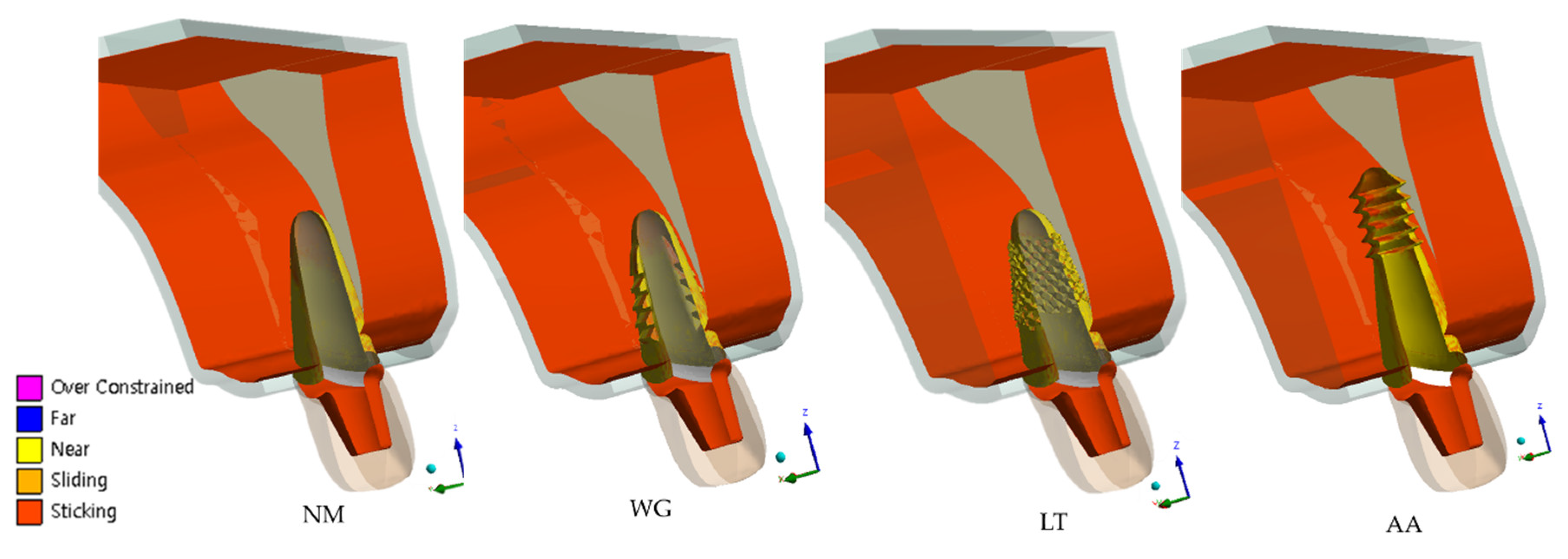
2.4. Contact Conditions
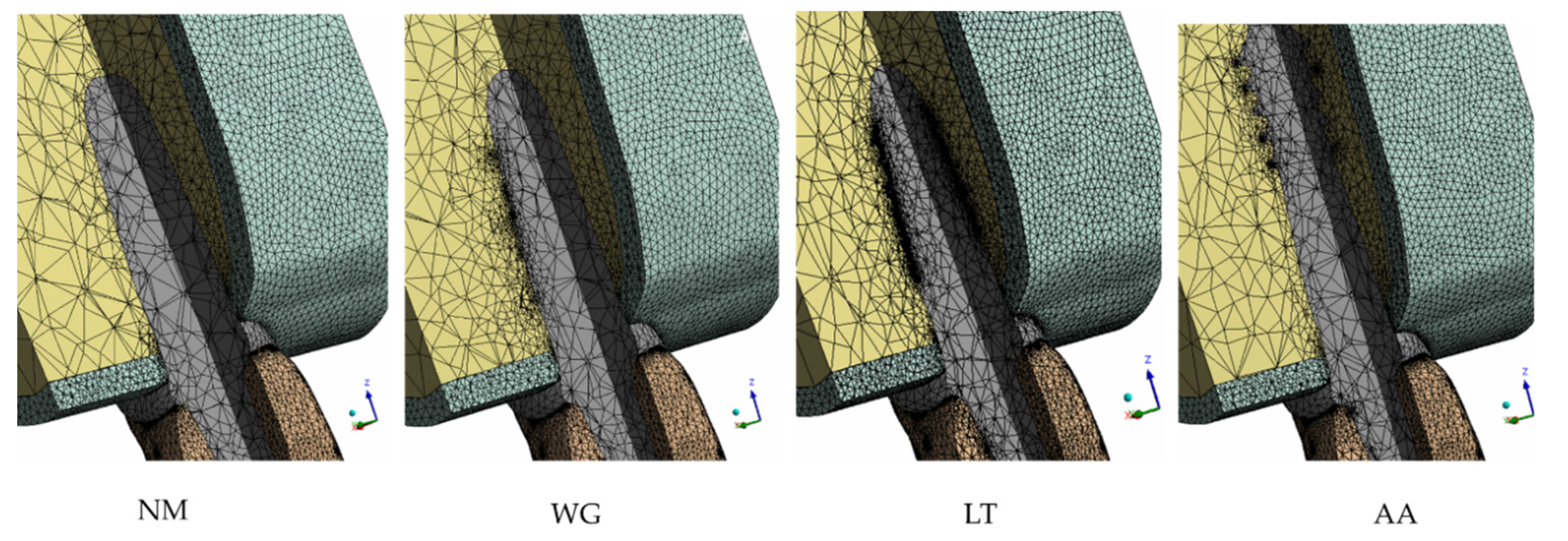
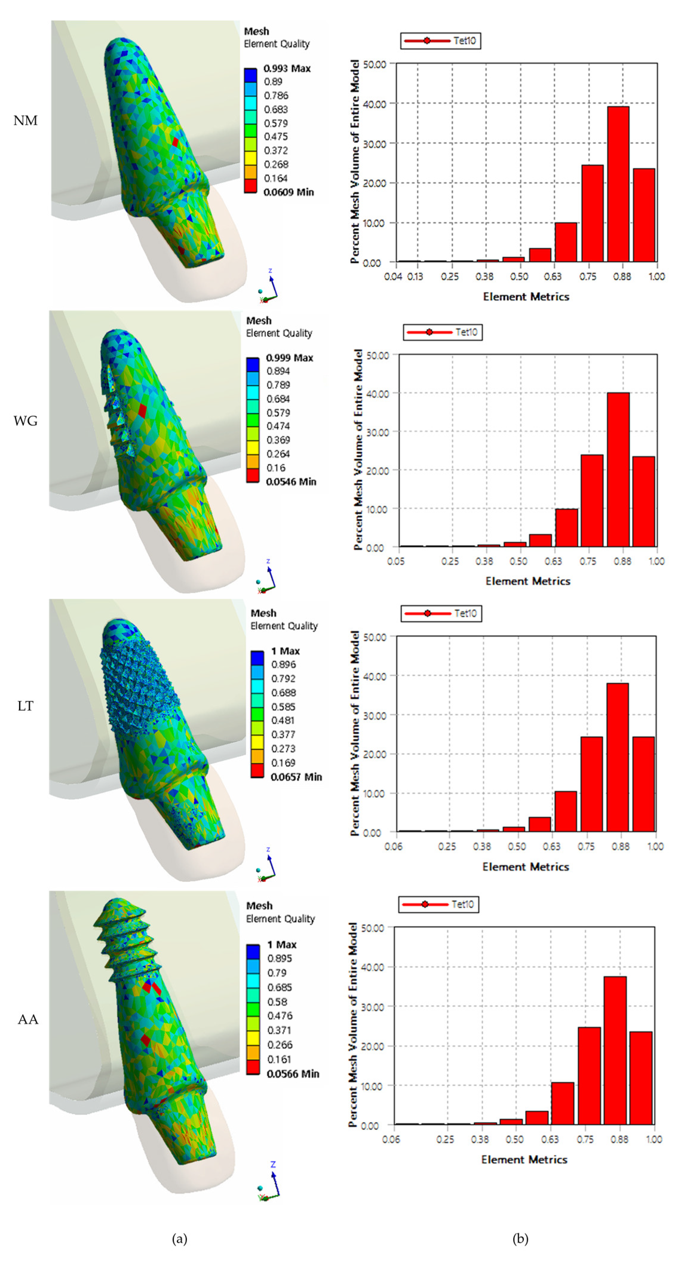
To simulate the immediate implant placement after tooth extraction (non-osseo-integrated situation), nonlinear surface-to-surface frictional contact conditions were employed at the implant–bone interface to allow for sliding behaviors [26,27]. The contact condition of the implant and bone is a condition where separation is allowed, and sliding occurs with a certain magnitude of frictional coefficient (COF). To observe the biomechanical behavior of each RAI design with insufficient initial stability, peak stress, and micro motion were observed with COF from 0.1 to 0.5.

2.5. Analysis

After model construction, all models were transferred to FEA software ANSYS 18® (ANSYS Inc., Canonsburg, PA, USA). Then, all models were meshed using tetrahedral elements with a lower limit of 0.02 mm in size was assigned (Figure 5). To check the quality of generated mesh [28], inspections for quality of elements were conducted after mesh generation (Figure 6). Whole mesh generations and finite element analysis was performed using a 64-bit version of Windows 10 and an Intel i9-990K processor with 64 gigabytes of random-access memory. The number of elements and nodes of each experimental group is described in Table 2. After the finite element analysis was completed, the contact statuses between the components constituting the model were checked (Figure 7).

3. Results

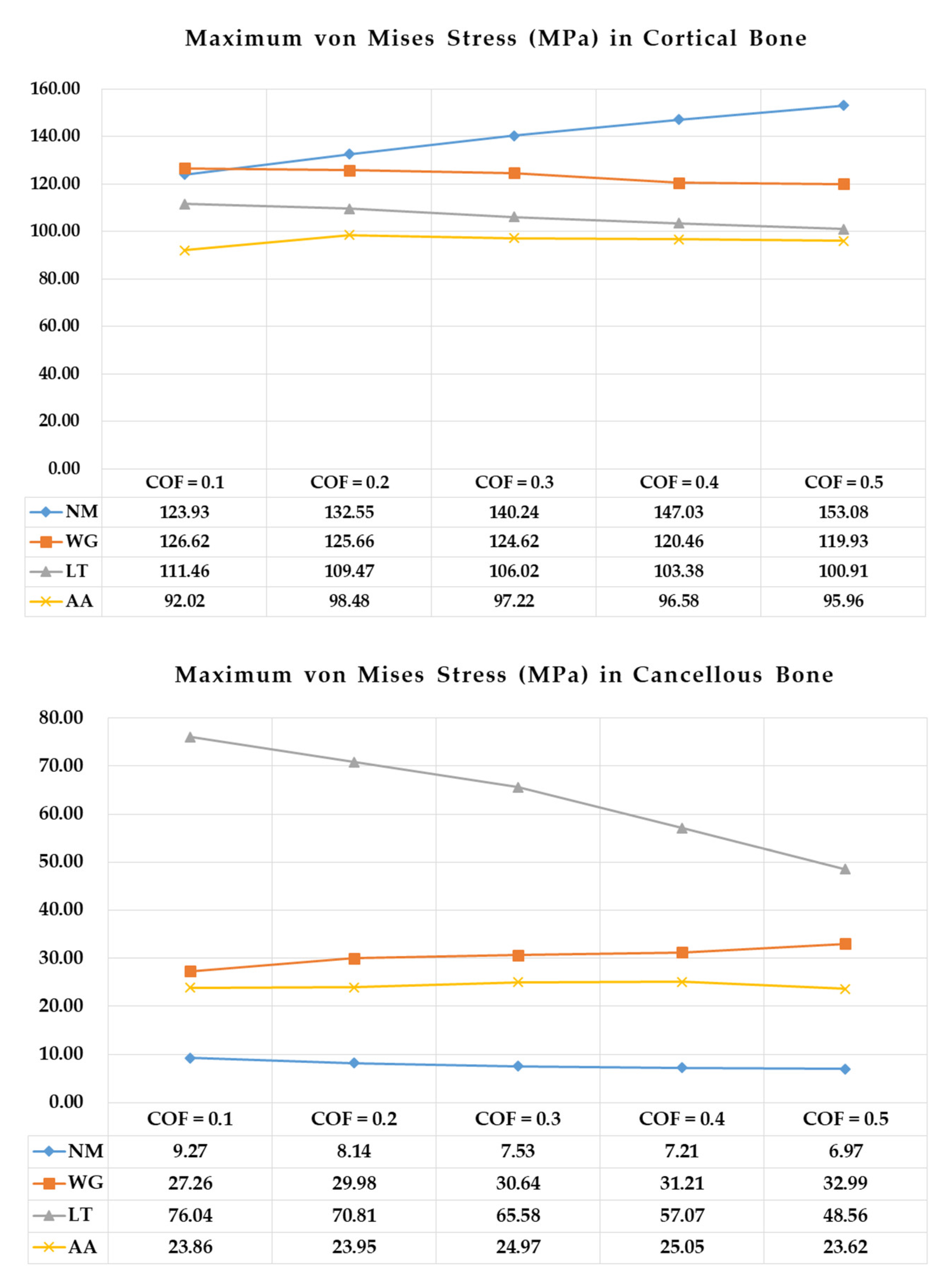
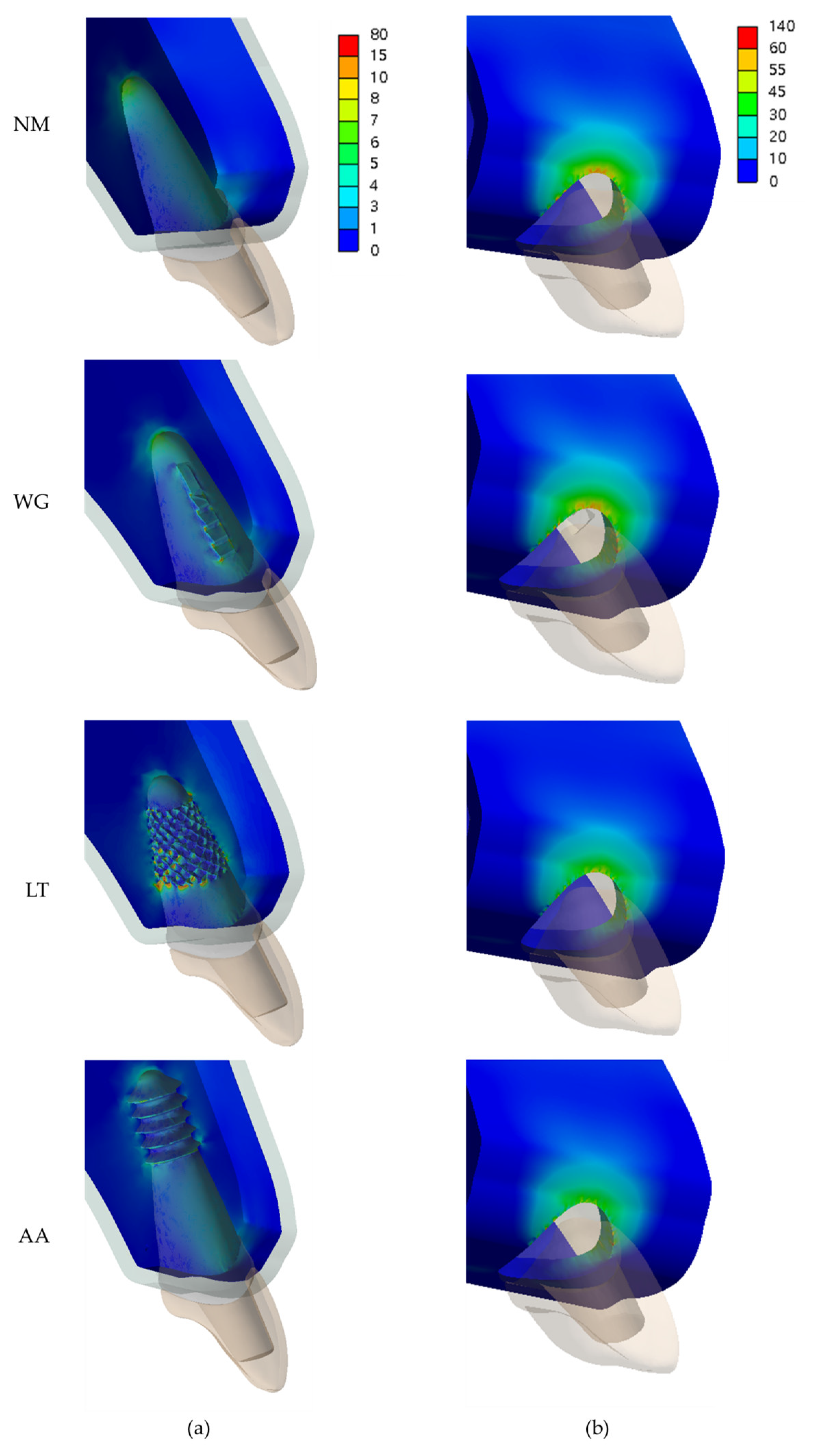
3.1. Stress Distribution on Surrounding Bones

Figure 8 presents the maximum von Mises stress values (in MPa) on the supporting cortical and cancellous bones in all experimental groups according to the frictional coefficient (COF) values. In cortical bone, the NM group exhibited the highest von Mises stress values according to all COF values, whereas the AA group exhibited the lowest von Mises stress values according to lower COF values. In cancellous bone, the NM group exhibited the lowest von Mises stress values according to all COF values, whereas the LT group exhibited the highest von Mises stress values according to all COF values. Notably, as the COF was lowered, the maximum von Mises stress on cancellous bone in the LT group tended to significantly increase when compared to the other experimental groups.
Figure 9 shows the stress distribution patterns on cortical and cancellous bone in all experimental groups according to the lowest COF values (COF = 0.1). In cortical bone, the maximum von Mises stresses were concentrated across the labial side of the bone in all experimental groups and according to all COF values. In cancellous bone, most stresses were concentrated in the cervical region adjacent to cortical bones in the NM study group. However, in the other study groups (WG, LT, and AA), most stresses were concentrated where the RAI penetrated the original tooth socket wall. In particular, in the LT group, the concentration of stresses was greater in the penetration site than in the cervical area, showing a different stress distribution pattern on cancellous bone than in the other study groups.

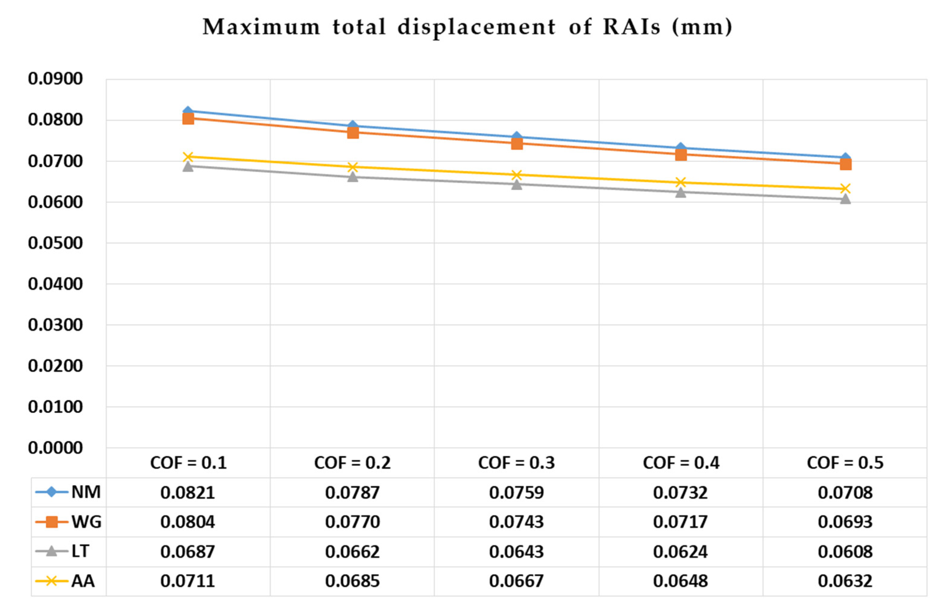
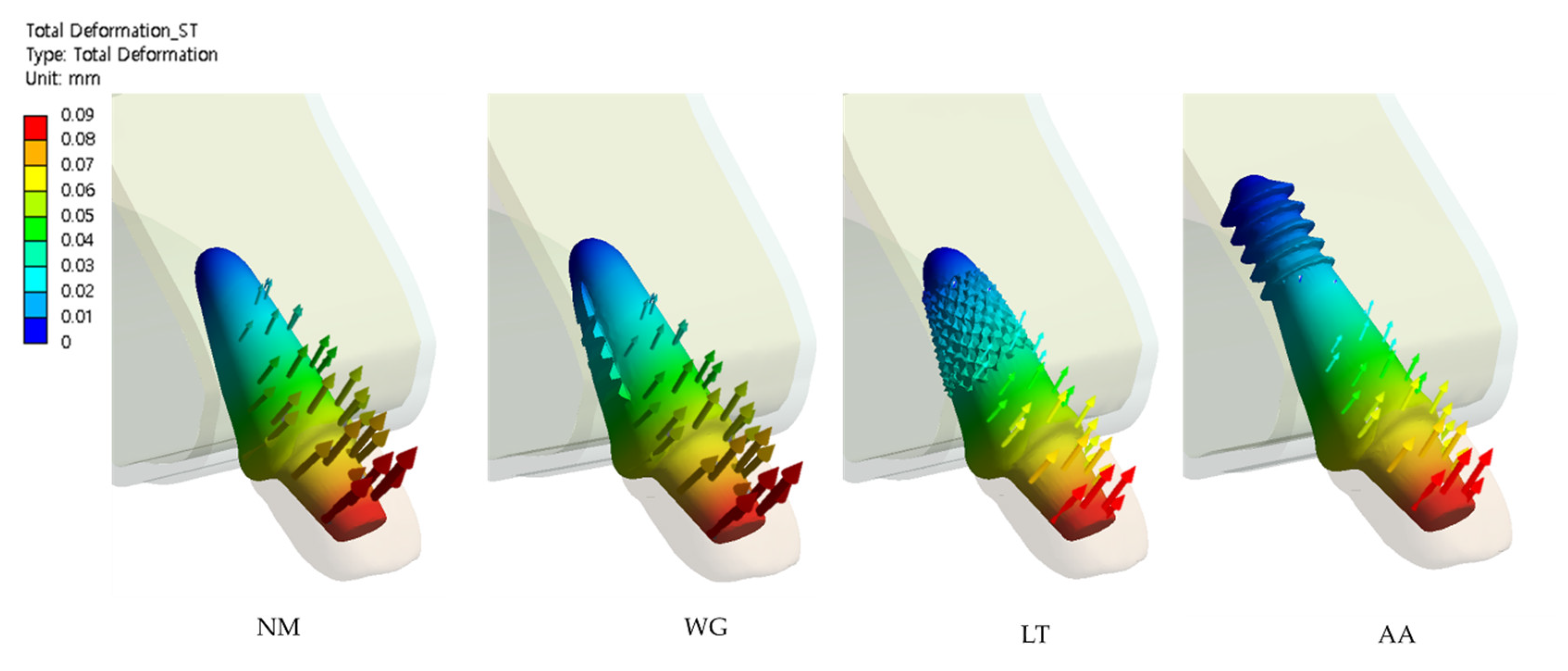
3.2. Micro-Displacement of RAIs

Figure 10 shows the micro-displacement of RAIs in each experimental group according to the COF values. In all study groups, there was a tendency for displacement to decrease with increasing COF values. The displacement values of the NM and WG groups were similar, as were those of the LT and AA groups. However, the values of the LT and AA groups showed significantly lower displacements than those of the NM and WG groups according to all COF values.
Figure 11 depicts the micro-displacement patterns of the RAIs in all experimental groups according to the lowest COF values (COF = 0.1) with directional vectors. In all study groups, regardless of RAI modification design, more micro-motions at the head of the implant occurred to the labial direction with the apical root of the implant as the center of rotation.

4. Discussion

In this study, the initial stability of a custom RAI design with drilling protocol was biomechanically evaluated by comparing it using a 3D FEA to other RAI designs without drilling protocols. Most previous research on the implantation of a patient-specific RAI after tooth extraction focuses mainly on achieving initial stability through modification of the root surface region, without considering additional drilling in the design of the RAI [19,20]. However, since the previous RAI implantation technique without additional drilling requires only a limited surface area (the tooth extraction socket), there is a limit to obtaining initial mechanical fixation immediately after implant placement. Therefore, we proposed a novel RAI design that requires additional drilling on surface area in addition to the surface of the tooth extraction socket.
In addition, we performed experiments assuming the bone-to-implant interface is under a frictional contact condition. Most previous studies that performed biomechanical analysis of dental implants using the FE method set the contact condition between bones and dental implants as a bonded state [29,30,31]. This interface condition is only suitable for a fully osseo-integrated implant, which cannot be immediately applied in implantation stages. Therefore, in this study, frictional contact conditions were applied between the bones and dental implants, allowing the implant to slide on the bone. Assuming low COF values at the bone-to-implant interface can simulate the initial stability of immediate implantation conditions [32]. The initial stability of dental implants, in other words, the mechanical stability, can be achieved through mechanical interlocking between the implant-to-bone interface, irrespective of biological interaction; this is the most significant clinical issue with dental implantation [33].
According to the stress distribution results of this study, the modified-RAI-surface experimental groups (WD, LT, and AA), which added the penetration shape to the original tooth extraction socket surface, had a positive effect on the stress reduction of the cortical bone than the NM group without any surface modification. Similar to the findings of a previous study [19], this effect is expected to occur when the stress caused by an external load is more burdened on the cancellous bone region due to an increase in the mechanical fixation of that region (Figure 8 and Figure 9). In addition, it should be considered that in the case of the LT group, the stress on the cancellous bone was significantly increased compared to the other groups, especially at a low COF, which may cause an overload on the cancellous bone. Therefore, the LT group results may be interpreted as follows: Over modification of the surface that induces excessive mechanical fixation may have a negative effect. However, in the AA group, which had a RAI that extended to the root apex rather than additional modification to the root surface, the stress concentration on the cortical bone was the lowest among all of the experimental groups and according to all COFs; the possibility of overload on the cancellous bone was also lower than in the LT group. Thus, it can be interpreted that the AA RAI design with additional drilling protocol can achieve favorable results in terms of stress distribution. In addition, Figure 8 showed that the region where the stress is very concentrated is closest to sharp margin of solid bodies of cortical bone. This region is the area around the dental implant neck, which coincides with the area where bone atrophy occurs due to overload in long-term clinical practice, which is similar to previous finite element analysis results and interpretations for dental implants [34].
According to the micro-displacement results of this study (Figure 10 and Figure 11), the addition of more modification shapes (LT group), more penetration of the tooth socket or RAI root surface, or intentionally lengthening the RAI by adding apex-anchorage (AA group) may have a positive effect on the reduction of RAI micro-motions. Considering the results of our numerical analysis, the AA design may minimize the stress burden on the cortical bone, avoid overload on the cancellous bone, and cause the least micro-motion.
With the recent development of CAD programs and 3D printer technology, unlimited modified RAIs designs are available. Regarding stress distribution and micro-displacement, we found that, if there are additional surrounding bones that can be used for initial mechanical fixation, a novel implantation technique that achieves initial fixation through additional drilling prior to RAI implantation may lead to more favorable biomechanical results than previous RAI designs using only the press-fit implantation technique.

5. Conclusions

Based on the results of this study and considering the limitations of the applied methodology, we found that additional drilling in the tooth extraction socket and use of an RAI with an apex-anchor has a positive effect on lowering the stress concentration on cortical bone and reducing micro-displacement of the RAI.

Author Contributions

Conceptualization, K.-S.L., W.-C.L. and S.-W.S.; Data curation, K.-S.L. and W.-C.L.; Formal analysis, K.-S.L. and W.-C.L.; Funding acquisition, S.-W.S.; Investigation, K.-S.L. and W.-C.L.; Methodology, K.-S.L. and W.-C.L.; Project administration, S.-W.S.; Resources, P.-G.K.; Software, K.-S.L. and P.-G.K.; Supervision, J.-M.P., K.-T.K., J.-J.R. and S.-W.S.; Validation, J.-M.P. and S.-W.S.; Visualization, W.-C.L.; Writing—original draft, K.-S.L. and W.-C.L.; Writing—review and editing, K.-S.L., W.-C.L., K.-T.K., J.-J.R. and S.-W.S. All authors have read and agreed to the published version of the manuscript.

Funding

This study was supported by the Technology Innovation Program (Material parts package business) (No.20001221, Development of high strength and fatigue resistance metal and manufacturing technology for root analogue dental implants) funded by the Ministry of Trade, Industry & Energy (MOTIE, Korea).

Acknowledgments

This research was supported by a grant from the Korea University Ansan Hospital (O1903561).

Conflicts of Interest

The authors declare no conflicts of interest. The funders had no role in the design of the study; in the collection, analyses, or interpretation of data; in the writing of the manuscript, or in the decision to publish the results.

References

  1. Lindh, T.; Gunne, J.; Tillberg, A.; Molin, M. A meta-analysis of implants in partial edentulism. Clin. Oral Implant. Res. 1998, 9, 80–90. [Google Scholar] [CrossRef] [Green Version]
  2. Moraschini, V.; Poubel, L.D.C.; Ferreira, V.F.; Barboza, E.D.S. Evaluation of survival and success rates of dental implants reported in longitudinal studies with a follow-up period of at least 10 years: A systematic review. Int. J. Oral Maxillofac. Surg. 2015, 44, 377–388. [Google Scholar] [CrossRef] [PubMed]
  3. Manicone, P.; Passarelli, P.; Bigagnoli, S.; Pastorino, R.; Manni, A.; Pasquantonio, G.; D’Addona, A.J.E.R.M.P.S. Clinical and radiographic assessment of implant-supported rehabilitation of partial and complete edentulism: A 2 to 8 years clinical follow-up. Eur. Rev. Med. Pharmacol. Sci. 2018, 22, 4045–4052. [Google Scholar] [CrossRef] [PubMed]
  4. Chen, J.; Zhang, Z.; Chen, X.; Zhang, X. Influence of custom-made implant designs on the biomechanical performance for the case of immediate post-extraction placement in the maxillary esthetic zone: A finite element analysis. Comput. Methods Biomech. Biomed. Eng. 2017, 20, 1–9. [Google Scholar] [CrossRef] [PubMed]
  5. Strub, J.R.; Jurdzik, B.A.; Tuna, T. Prognosis of immediately loaded implants and their restorations: A systematic literature review. J. Oral Rehabil. 2012, 39, 704–717. [Google Scholar] [CrossRef]
  6. Kim, J.-H.; Lee, J.-G.; Han, D.; Kim, H.-J. Morphometric analysis of the anterior region of the maxillary bone for immediate implant placement using micro-CT. Clin. Anat. 2011, 24, 462–468. [Google Scholar] [CrossRef] [PubMed]
  7. Figliuzzi, M.; Mangano, C.; Mangano, C. A novel root analogue dental implant using CT scan and CAD/CAM: Selective laser melting technology. Int. J. Oral Maxillofac. Surg. 2012, 41, 858–862. [Google Scholar] [CrossRef] [PubMed]
  8. Pirker, W.; Kocher, A. Immediate, non-submerged, root-analogue zirconia implant in single tooth replacement. Int. J. Oral Maxillofac. Surg. 2008, 37, 293–295. [Google Scholar] [CrossRef]
  9. Pirker, W.; Kocher, A. Immediate, non-submerged, root-analogue zirconia implants placed into single-rooted extraction sockets: 2-year follow-up of a clinical study. Int. J. Oral Maxillofac. Surg. 2009, 38, 1127–1132. [Google Scholar] [CrossRef]
  10. Pirker, W.; Wiedemann, D.; Lidauer, A.; Kocher, A. Immediate, single stage, truly anatomic zirconia implant in lower molar replacement: A case report with 2.5 years follow-up. Int. J. Oral Maxillofac. Surg. 2011, 40, 212–216. [Google Scholar] [CrossRef]
  11. Mangano, C.; De Franco, M.; Caprioglio, A.; Macchi, A.; Piattelli, A.; Mangano, C. Immediate, non-submerged, root-analogue direct laser metal sintering (DLMS) implants: A 1-year prospective study on 15 patients. Lasers Med. Sci. 2013, 29, 1321–1328. [Google Scholar] [CrossRef]
  12. Lundgren, D.; Rylander, H.; Anderssong, M.; Johansson, C.; Albrektsson, T. Healing-in of root analogue titanium implants placed in extraction sockets. An Experimental Study in the Beagle Dog. Clin. Oral Implant. Res. 1992, 3, 136–144. [Google Scholar]
  13. Kohal, R.; Klaus, G.; Strub, J.J.D.Z.Z. Clinical investigation of a new dental immediate implant system-the Relmplant-system. Deutsche Zahnarztliche Zeitschrift 2002, 57, 495–497. [Google Scholar]
  14. Mangano, C.; Cirotti, B.; Sammons, R.L.; Mangano, C. Custom-made, root-analogue direct laser metal forming implant: A case report. Lasers Med. Sci. 2012, 27, 1241–1245. [Google Scholar] [CrossRef] [PubMed]
  15. Yoon, Y.; Sun, X.; Huang, J.-K.; Hou, G.; Rechowicz, K.; McKenzie, F.D. Designing Natural-Tooth-Shaped Dental Implants based on Soft-Kill Option Optimization. Comput. Des. Appl. 2013, 10, 59–72. [Google Scholar] [CrossRef]
  16. Steigenga, J.; Al-Shammari, K.; Misch, C.; Nociti, F.H.; Wang, H.-L. Effects of Implant Thread Geometry on Percentage of Osseointegration and Resistance to Reverse Torque in the Tibia of Rabbits. J. Periodontol. 2004, 75, 1233–1241. [Google Scholar] [CrossRef] [PubMed]
  17. Moin, D.A.; Hassan, B.; Parsa, A.; Mercelis, P.; Wismeijer, D. Accuracy of preemptively constructed, C one B eam CT-, and CAD/CAM technology-based, individual R oot A nalogue I mplant technique: An in vitro pilot investigation. Clin. Oral Implant. Res. 2014, 25, 598–602. [Google Scholar] [CrossRef] [PubMed]
  18. Moin, D.A.; Hassan, B.; Mercelis, P.; Wismeijer, D. Designing a novel dental root analogue implant using cone beam computed tomography and CAD/CAM technology. Clin. Oral Implant. Res. 2011, 24, 25–27. [Google Scholar] [CrossRef]
  19. Moin, D.A.; Hassan, B.; Wismeijer, D. A Patient Specific Biomechanical Analysis of Custom Root Analogue Implant Designs on Alveolar Bone Stress: A Finite Element Study. Int. J. Dent. 2016, 2016, 1–8. [Google Scholar] [CrossRef] [Green Version]
  20. Evans, Z.P.; Renne, W.; Bacro, T.R.; Mennito, A.; Ludlow, M.E.; Lecholop, M.K. Anatomic Customization of Root-Analog Dental Implants With Cone-Beam CT and CAD/CAM Fabrication: A Cadaver-Based Pilot Evaluation. J. Oral Implant. 2018, 44, 15–26. [Google Scholar] [CrossRef]
  21. Van Staden, R.C.; Guan, H.; Loo, Y.C. Application of the finite element method in dental implant research. Comput. Methods Biomech. Biomed. Eng. 2006, 9, 257–270. [Google Scholar] [CrossRef] [PubMed] [Green Version]
  22. Gattinger, J.; Bullemer, C.N.; Harrysson, O. Patient specific root-analogue dental implants—additive manufacturing and finite element analysis. Curr. Dir. Biomed. Eng. 2016, 2, 101–104. [Google Scholar] [CrossRef]
  23. Picanco, P.R.; Valarelli, F.P.; Cancado, R.H.; Freitas, K.; Picanço, G.V. Comparison of the changes of alveolar bone thickness in maxillary incisor area in extraction and non-extraction cases: Computerized tomography evaluation. Dent. Press J. Orthod. 2013, 18, 91–98. [Google Scholar] [CrossRef] [PubMed]
  24. García-Braz, S.H.; Prados-Privado, M.; Zanatta, L.C.S.; Calvo-Guirado, J.L.; Prados-Frutos, J.C.; Gehrke, S.A. A Finite Element Analysis to Compare Stress Distribution on Extra-Short Implants with Two Different Internal Connections. J. Clin. Med. 2019, 8, 1103. [Google Scholar] [CrossRef] [Green Version]
  25. Yamanishi, Y.; Yamaguchi, S.; Imazato, S.; Nakano, T.; Yatani, H. Influences of implant neck design and implant–abutment joint type on peri-implant bone stress and abutment micromovement: Three-dimensional finite element analysis. Dent. Mater. 2012, 28, 1126–1133. [Google Scholar] [CrossRef] [PubMed] [Green Version]
  26. Grant, J.; Bishop, N.E.; Götzen, N.; Sprecher, C.; Honl, M.; Morlock, M. Artificial composite bone as a model of human trabecular bone: The implant–bone interface. J. Biomech. 2007, 40, 1158–1164. [Google Scholar] [CrossRef]
  27. Huang, H.-L.; Hsu, J.-T.; Fuh, L.-J.; Tu, M.-G.; Ko, C.-C.; Shen, Y.-W. Bone stress and interfacial sliding analysis of implant designs on an immediately loaded maxillary implant: A non-linear finite element study. J. Dent. 2008, 36, 409–417. [Google Scholar] [CrossRef]
  28. Żmudzki, J.; Panek, K.; Chladek, G.; Adamiak, M.; Lipinski, P. Finite Element Analysis of Adolescent Mandible Fracture Occurring during Accidents. Arch. Metall. Mater. 2018, 2020. [Google Scholar] [CrossRef]
  29. Winter, W.; Klein, D.; Karl, M. Effect of Model Parameters on Finite Element Analysis of Micromotions in Implant Dentistry. J. Oral Implant. 2013, 39, 23–29. [Google Scholar] [CrossRef]
  30. Carvalho, M.A.; Sotto-Maior, B.S.; Cury, A.D.B.; Henriques, G.E.P. Effect of platform connection and abutment material on stress distribution in single anterior implant-supported restorations: A nonlinear 3-dimensional finite element analysis. J. Prosthet. Dent. 2014, 112, 1096–1102. [Google Scholar] [CrossRef]
  31. Ghadiri, M.; Shafiei, N.; Salekdeh, S.H.; Mottaghi, P.; Mirzaie, T. Investigation of the dental implant geometry effect on stress distribution at dental implant–bone interface. J. Braz. Soc. Mech. Sci. Eng. 2015, 38, 335–343. [Google Scholar] [CrossRef]
  32. Murakami, N.; Wakabayashi, N. Finite element contact analysis as a critical technique in dental biomechanics: A review. J. Prosthodont. Res. 2014, 58, 92–101. [Google Scholar] [CrossRef] [PubMed]
  33. Li, J.; Jansen, J.A.; Walboomers, X.F.; Beucken, J.J.V.D. Mechanical aspects of dental implants and osseointegration: A narrative review. J. Mech. Behav. Biomed. Mater. 2020, 103, 103574. [Google Scholar] [CrossRef] [PubMed]
  34. Żmudzki, J.; Malara, P.; Chladek, G. Full contoured tooth-implant supported 3-pointic all-ceramic denture during occlusal load transfer in lateral region Arch. Metall. Mater. 2016, 61, 843–846. [Google Scholar] [CrossRef]
Figure 1. Four modified root analogue implant (RAI) designs of each experimental group. Dimensions and notations of the geometric properties are as follows: H1: the height of implants without additional drilling protocol (=16.13 mm). H2: the height of implants with additional drilling protocol (=19.25 mm). NM-RAI: non-modified surface designed RAI; WG-RAI: wedge shape added at mesial and distal root surface of RAI. The height and width of the wedge are 0.6 mm and 1.0 mm, respectively; LT-RAI: lattice shape added at root surface RAI. The height of the protruding lattice and the width of the floor are equal to 0.3 mm; AA-RAI: apex-anchor added RAI. Thread protrusion is from 0.3 to 0.6 mm. Thread distance is 1.0 mm. H1 is the length value of the teeth scanned in this study. H2 is 3.12 mm added to the value of H1, which is the value that assumed the length of the implant drill apex tip to be 0.12 mm plus 3 mm, which is half of 6 mm, the shortest implant length of most commercial implants, in order to prevent too deep drilling.
Applsci 10 04104 g001
Figure 2. 2D sectional view of the non-modified root surface (MN) group to explain the mutual relationship with the components constituting one experimental group.
Applsci 10 04104 g002
Figure 3. The sectional view of assembled root analogue implant (RAI) components of each experimental group. NM: group implanted with the non-modified surface designed RAI; WG: group implanted with the RAI with a wedge shape added at mesial and distal root surface; LT: group implanted with the lattice shape added at root surface RAI; AA: group implanted with the apex-anchor added RAI.
Applsci 10 04104 g003
Figure 4. Boundary conditions and applied load. The red triangles on the top surface of the maxillary bone indicates a fixed boundary condition. The selected geometry surface of the palatal side of crown where 100 N load is applied is marked as green.
Applsci 10 04104 g004
Figure 5. Sectional view of generated meshes in enodosteal region of each experimental group.
Applsci 10 04104 g005
Figure 6. Quality of elements in RAIs (a) and statistics (b) of each experimental group.
Applsci 10 04104 g006
Figure 7. Sectional view of contact status of each experimental group after finite element analysis (FEA) completed.
Applsci 10 04104 g007
Figure 8. Maximum von Mises stress (MPa) values on cortical and cancellous bones in each experimental group according to the frictional coefficient (COF) values.
Applsci 10 04104 g008
Figure 9. Maximum von Mises stress (MPa) on cancellous bone (a) and cortical bone (b) in each experimental group according to the lowest frictional coefficient values (COF = 0.1). Abbreviations: non-modified root surface (NM); wedge shape added at mesial and distal root surface (WG); lattice shape added at root surface (LT); apex-anchor added (AA).
Applsci 10 04104 g009
Figure 10. Micro-displacement values of root analogue implants (RAIs) in each experimental group according to all frictional coefficient (COF) values.
Applsci 10 04104 g010
Figure 11. Micro-displacement patterns of root analogue implants (RAIs) in each experimental groups respect to the lowest frictional coefficient (COF) values (COF = 0.1) with directional vectors.
Applsci 10 04104 g011
Table 1. Mechanical properties of all materials used.
MaterialYoung’s Modulus (GPa)Poisson’s Ratio
Cortical bone13.70.3
Cancellous bone1.370.3
Titanium grade 5 (Ti6Al4V)113.80.342
Esthetic ceramic690.3
Table 2. The number of elements and nodes of each experimental group.
NMWGLTAA
Nodes683,939813,1642,329,462948,758
Elements443,189527,6041,517,408614,022

