Abstract
The paper investigated studies on the application of pulsed electric fields for the treatment of liquid media in a continuous manner in a co-field treatment chamber with elliptic insulator profiles. The electric field distribution and the temperature rise in the treatment chamber were evaluated via the finite element method. A non-uniform electric field was found at the elliptical insulator edges, while the electric field distribution on the insulator surface was rather uniform. The maximum temperature rise in the liquid media was located slightly behind the elliptic insulator due to the accumulated heat in the flowing liquid media. In the optimized treatment chamber, the average electric field intensity could be as high as 12.21 kV/cm at the moderate voltage at 7.5 kV. As a strategy to improve the inactivation while limiting the temperature rise, a series of treatment chambers was verified by experiments under the conditions of 7.5 kV, a 2.5% duty cycle, and 250 Hz. It was found that an increase in the treatment units could increase the inactivation efficiency for Escherichia coli. The average log reduction could be improved from 1.82 to 2.39 when the number of treatment units was increased from 1 to 5, respectively.
1. Introduction
Among the non-thermal pasteurization techniques, the method of pulsed electric fields (PEF) is still under intensive study and has a prospect for practical use. The pulsed electric field method is considered a promising technique for the aseptic processing of foods [1,2,3,4,5,6]. The principle of the PEF method is the application of a high electric field to induce poration on the membrane of target microorganisms, leading to the inactivation of microorganisms due to the permanent disruption of the membrane. Pores on the microorganism’s membrane are induced by the accumulation of charges on both sides of the membrane, resulting in a transmembrane potential. The induced transmembrane potential (vm) has to be larger than the natural potential of the cell membrane to create a pore. The value of the critical vm for the poration depends on the type, size, and shape of microorganisms, and it typically ranges from 0.5 to 1.5 volts. This process is called electroporation [1,2,7,8,9,10,11,12].
The utilization of pulsed electric fields is now widely studied for food industry applications to increase the shelf life of foods due to a variety of merits, which can be described as follows. This method consumes a small amount of energy for treatment as the energy is needed only for inducing the breakdown of the microbial membrane, not for generating heat. With optimal pulse parameters (time, frequency, etc.), it is possible to control the increase in the temperature of the treated samples, thus limiting the influences of the treatment on the nutritional contents, appearance, and taste of the food product. Even though the PEF technique for food pasteurization has been proposed for more than 50 years, there are still issues needed that to be clarified for the use of PEF in practice. This is due to the fact that there is a variation in the types of microorganisms and in the natures of food materials, which need different treatment conditions for the PEF treatment. Moreover, the treatment chamber or actuator design, electrode geometries, electric pulse characteristics, electric field intensity, and other process factors also affect the treatment efficiency for the specific microbial inactivation of liquid foods [2,3,7,11,13,14,15]. Generally, the PEF technique requires a very short pulse width (1–100 microseconds), with magnitudes in the range of 5–50 kV/cm. The treatment should operate with a short residence time (lower than 1 s) at a 20–60 °C liquid food temperature to allow efficient microorganism inactivation with a high level of food safety [2,7,13,16].
However, the disadvantage of current PEF technology in static liquid treatment is the requirement of considerable operation energy, because a large treatment system is usually used to reduce the operating time for liquid replacement. In this type of the treatment process, a liquid medium is usually stored in a large treatment chamber, and time-consumingly treated with a very high pulsed voltage, dependent on the size and distance of electrodes, to satisfy the electroporation criteria for microbial inactivation [2,7,17,18,19]. Therefore, the requirement of an expensive pulsed voltage generator is unavoidable. The possibility of solving this problem would be an application of the PEF treatment with a flow-through system [3,4,13,14,17,20,21,22,23,24,25]. In this type of treatment system, the PEF treatment chamber could be in-line equipped in the liquid food production line. Therefore, the PEF chamber size, the magnitude of the pulsed voltage generation, and the time and energy consumption could be decreased. However, the design of the PEF treatment chamber including the treatment parameters is rather complicated. Most of these PEF treatment types require a re-circulation pumping system for the re-treatment process to improve the inactivation efficiency. Therefore, the issue of time consumption is still incompletely resolved.
Recently, the flow-through liquid treatment chamber has been focused on due to the aforementioned advantages. The treatment chambers have been developed into several configurations, such as parallel, coaxial, and co-field or co-linear treatment chambers [14,20,22,25,26,27]. However, the co-field treatment chamber seems to have preferable geometry. The co-field treatment chamber is composed of two hollow electrodes separated by an insulator. In this chamber configuration, the electric field distribution is not highly uniform due to the interface between the electrode and insulator. The PEF systems could be operated at lower power in comparison with the static treatment system [22,28,29]. The insulator profile can significantly reduce the maximum field at the interface between the electrode and insulator, resulting in joule heating reduction. It should be noted that during the PEF processes, joule heating is unavoidable since electric current passes through a conductive liquid food. The heat may affect the quality of the treated food. Therefore, how to design the optimal insulator profile for the co-field treatment chamber is an essential and challenging topic [5,13,14,15,20,28,30]. In addition, the use of treatment electrodes arranged in a series manner for the purpose of temperature control and treatment efficiency enhancement has not been fully investigated in the literature up to now.
In this research, the study aimed to focus on the application of the PEF method in order to yield an efficient non-thermal treatment process for the inactivation of microorganisms in a liquid substance. The influences of the electrode and insulator geometry on the electric field strength distribution in the co-field chamber were optimized by the simulation of the finite element method (FEM). Then, an application of the proposed co-field chamber with the elliptic insulator types would be verified by experiments in the non-recirculate flow-through system. In this instance, Escherichia coli (E. coli), which is one of the most common inadmissible intestinal pathogenic bacteria in the food industry, is of interest. The pulsed electric fields have been studied for the effective treatment of E. coli suspensions. In addition, the use of energizing electrodes in series is analyzed to enhance the treatment efficiency.
2. Materials and Methods
2.1. Co-Field Treatment Chamber Configuration
The axisymmetric configuration, along the z-axis, of a co-field treatment chamber with an elliptic insulator for the proposed treatment chamber is depicted in Figure 1. One unit (NHV1) of the electrode couple consists of two treatment zones. The radius of the treatment chamber (r) is 2.5 mm, and the length of the inlet and outlet ground electrodes (L) is 20 cm. The grounded electrode length (A), the elliptic insulator length (B), the high voltage electrode length (C), and the elliptic insulator height (h) have been optimized to maximize the electric field strength at the treatment zone by the FEM simulation. The number of electrode couples could be added in by using the ground electrode to connect each unit of the electrode couple, arranged in series. It should be noted here that the gap between each electrode couple is A (in mm), while the ground electrodes at the inlet and outlet of the set of multi-unit of electrode couple are 20 mm in order to avoid the turbulent flow entering the treatment chambers.
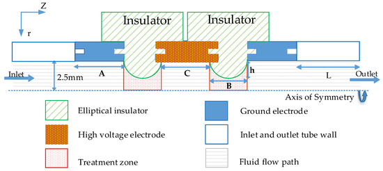
Figure 1.
Schematic drawing of the co-field treatment chamber with one treatment unit (NHV1) of high voltage electrode.
2.2. E. coli and Treated Liquid Medium Preparations
The standard laboratory strain of Escherichia coli or E. coli (TISTR Number 074) obtained from Thailand Institute of Scientific and Technological Research (TISTR) was used for the original E. coli culture stocks. One colony of E. coli from the culture stock was diluted in 5 mL of liquid nutrient broth media, and incubated at 30 ± 0.1 °C for the 1st E. coli liquid stock. After 18 h of incubation, 1 mL of E. coli solution was diluted in 1000 mL of 121 °C autoclaved reverse osmosis (RO) water and incubated again for 3 h to obtain the E. coli culture in the stationary growth phase for the 2nd E. coli liquid stock. Then, the treated liquid media were prepared by the dilution of 6–7 mL of the 2nd E. coli liquid stock in 1000 mL of autoclaved RO water. The final concentration of E. coli in the treated liquid media was around 1.7 × 10¹⁰ CFU/mL, and the electrical conductivity of the RO water increased from 0 to 0.18 mS/cm.
Viable cell counts were determined by the drop plating method on standard agar culture plates. The treated liquid medium in each serial dilution was centrifuged at 2800 rpm by a vortex mixer before the serial dilution sampling. Each culture plate was divided into 6 sectors depending on each serial dilution, ranging from 102 to 107 dilution of the treated liquid media. In each dilution zone, 5 drops of 10 µL of treated liquid medium were dropped. All the preparation and cell culture processes were conducted in a laminar flow cabinet. The culture plates were then incubated for 18 h before viable cell counts. In each experiment, 2 culture plates were duplicated for each experimental condition. The total experiment consisted of 5 experimental sets, which were performed once each on three different days for statistical analysis. The inactivation of E. coli was evaluated on average by calculating the log reduction in the viable cell counts in the serial dilution sector, which contained fewer than 30 colonies per 10 µL drop. The viable cell counts for all the experimental conditions were compared and statistically analyzed by one-way analysis of variance (ANOVA) using a significance level of 0.05 (p < 0.05).
2.3. Implementation of the PEF Treatment for Microorganism Inactivation
The co-field treatment chamber configuration was determined based on the simulation results [22,28]. In the current work, we aimed to experimentally verify the implementation of the proposed PEF chamber for E. coli inactivation in flowing liquid media. Figure 2 illustrates the schematic diagram of a PEF treatment operation. A high voltage DC (HVDC) power supply (Matsusada AU-30P10) was applied to the system via a 3 MΩ-charging resistor (RB). A 200 pF-capacitor (CS) acted to store the energy delivered from the RB. When the capacitor was fully charged, the energy (pulsed voltage) was discharged to the treatment chamber via a HV solid-state trigger switch (Behlke, HTS 201-03-GSM). Resistors, RsP and RsN, were used to control the trigger switch effect on the rise time of the output pulsed voltage. Their values were 200 Ω and 1 MΩ, respectively.
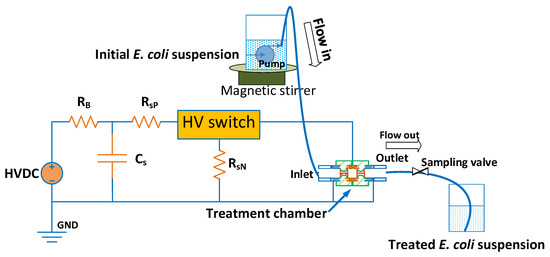
Figure 2.
The schematic diagram of a pulsed electric fields (PEF) treatment operation.
The initial treated E. coli suspension in a beaker placed on a magnetic stirrer was flowed through the PEF treatment chamber via a submersible pump with a flow rate of 10 mL/min. Therefore, the mass flow rate during the treatment process in the treatment zone would have been 0.14 g/s approximately. Before an experimental run, the flow-through system was sterilized with 95% ethanol pumped through the system for 15 min. Then, the system was cleaned with sterilized autoclaved RO water again. Before the PEF treatment process, to remove the residual cleaning RO water in the system, the E. coli solution was flowed through the system to the downstream storage beaker. The PEF treatment was conducted at the source voltage of 7.5 kV, at 250 Hz, with a 2.5% duty cycle. The PEF treatment chambers were 5 units connected in series; however, only the high voltage electrodes of the involved units were connected to the high voltage pulse source, while the others were grounded, as shown in Figure 3. In this work, the numbers of high voltage electrode (NHV) were 1, 3, and 5 units to study the influence of the number of electrode units on the efficacy of E. coli inactivation. In each experimental condition including the untreated condition (0 V), the HVDC and HV switch were operated to treat the initial E. coli suspension totally for 6 min during the treatment process. A 20 mL sampling of the treated E. coli suspension was performed at the sampling valve after the third minute of the treating process for the laboratory measurement of E. coli.
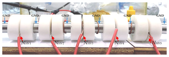
Figure 3.
The serial connection of 5 units of the treatment chamber.
The characteristics of the pulsed voltage and current were monitored using an oscilloscope (Siglent SDS2304). A high voltage probe (Pintek HVP-18HF) was used to monitor the voltage across the treatment unit. A 100 Ω monitored resistor (RM) was connected between the ground electrode and the system ground to observe the pulsed current waveform.
3. Experimental Results and Discussion
3.1. Electric Field and Temperature Field
Regarding the proposed co-field treatment chamber configuration in Section 2.1, the treatment chamber configuration parameters of the grounded electrode (A), the elliptic insulator (B) and the high voltage electrode length (C), and the elliptic insulator height (h) had been optimized to maximize the electric field strength at the treatment zone from the FEM simulation using Elmer FEM, an open source multiphysical simulation software. The GiDTM commercial software was used to draw the electrode configuration and generate a mesh for the co-field treatment chamber.
The FEM simulation was performed as follows. The finite element governing equation for the potential Φ in this paper is ∇2Φ = 0. The electric field normal to the boundary conditions surface of the inlet, outlet, insulator, and asymmetrical axis was set as zero, while the high voltage electrode and ground electrode boundary conditions were set as Φ = 7.5 kV and Φ = 0, respectively. The liquid flow was assumed to be laminar flow with an average inlet flow velocity of 0.05 m/s (Reynold number, Re = 499). The tangent velocity at the boundary condition of high voltage, insulator, and ground electrodes was zero. The material properties chosen from the Elmer library were applied to the fluid (Escherichia coli (E. coli) suspension). However, the electrical conductivity of water was adjusted, followed by the actual solution, to 0.018 mS/cm. The temperature of the water at the inlet and the external temperature were set as room temperature (25 °C) with natural convection. The heat transfer coefficient at the metal electrodes and the heat flux of the outlet and insulator surface were 2000 W/m2K and 0 W/m2, respectively.
Regarding previous studies on the co-field treatment chamber designed in [26,30], it was found that the electric field intensity at the treatment zone was affected by the high voltage electrode length and the insulator height. A highly non-uniform electric field was found at the junction between the elliptical insulator and the high-voltage (z = 20.5 mm)/grounded electrode (z = 26.5 mm), where z is the distance from the inlet to outlet along the asymmetrical axis, while the electric field distribution on the insulator surface was rather uniform, as shown in Figure 4a,b. However, the height of the insulator could affect the slight turbulent flow and accumulating heat in the flowing liquid [3,14,21,28,30], as shown in Figure 5. Since the effectiveness of microbial inactivation is strongly dependent on the electric field intensity, it could be difficult to avoid the accumulating heat in the liquid media resulting from the high pulsed electric field without an extra external cooling system. Our suggestion is that a serial connection of the treatment chamber would enable the reduction of the required intensity of the high-pulsed electric field and the maximum temperature of the liquid media compared with a single treatment chamber. This is since the increase in the number of the treatment chambers would increase the residence treatment time and the probability of microorganism treatment. However, too high numbers of treatment chambers would also lessen the inactivation efficiency due to sharing of energy among the treatment chambers, where the capacity of the power supply is limited. Therefore, based on the aforementioned discussion, A, B, C, and h were optimized to be 20, 6, 5, and 0.8 mm, respectively, and the maximal number of the treatment chamber was 5 units. For this geometry, the volume of one treatment zone would be 83.13 mm3, approximately.
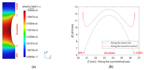
Figure 4.
Simulation results for (a) Electric field intensity, and (b) electric field intensity distribution along the insulator surface and symmetrical line in the first treatment zone.
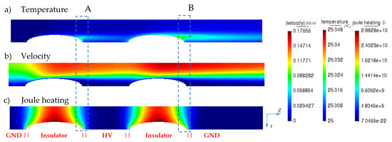
Figure 5.
Simulation results for the liquid’s (a) temperature, (b) velocity, and (c) joule heating along the z-axis at the first treatment chamber (NHV1).
It could be seen in Figure 4b that the electric field intensity in the treatment zone was rather uniform near the center of the insulator, which occupies almost half of the length of the insulator. For the proposed configuration, the maximum and average electric field intensities at the treatment zone were as high as 12.66 and 12.21 kV/cm at the supplied pulsed voltage of 7.5 kV, respectively. It should be noted that all the treatment zones have the same distribution of electric field intensity.
Joule heating could be generated in the conductive liquid media, since an amount of current could flow through the media once the high voltage was applied to the treatment chamber. It not only causes a thermal rise in the liquid media but also influences the profile of the flowing liquid’s viscosity and density [13,28,30]. Figure 5a presents the simulation results for the temperature rise in the treatment system. It could be noticed that the most accumulating thermal spots were found at the locations behind the elliptical insulators indicated by the letters A and B, which are the locations with the highest temperatures at the first and second insulators of each treatment unit. This issue comes from the combination of many factors, such as the fluid flow velocity, electric field distribution, and joule heating.
During the treatment process, the liquid heated in the treatment zone continued flowing along the z-axis. However, the fluid velocity near the insulator surface is close to zero (a blue vortex-like region in Figure 5b) This could imply that the temperature rise, generated owing to joule heating in the treatment zone (Figure 5c), could slowly diffuse to the tube wall. This results in thermal accumulation in the regions A and B, which are slightly behind the maximal joule heating region. Since the region A is in the first treatment zone, there was no thermal accumulation in the liquid before. The treated liquid from the first treatment zone would flow to the second treatment zone. During the flow, some amount of thermal energy would diffuse to the metal ground electrode, resulting in the reduction of the treated liquid medium temperature. However, the distance of the metal electrode is not long enough to diffuse the entire generated heat. Therefore, the heated liquid medium from the first treatment zone will be heated up again, owing to the joule heating in the second treatment zone [3,14,21,28,30] This reason causes the temperature to rise at region B higher than that at region A.
However, the PEF system containing a single unit of a high voltage electrode (NHV1) in the non-recirculated treatment system practically requires a high pulsed voltage to efficiently inactivate the microorganism, since there is only one short treatment period for one round of treatment. The high-pulsed voltage, in this case, would cause the more serious problem of a temperature rise and troublesome electrochemical reactions in the liquid media [3,14,21,28,30,31]. Therefore, a series of multiple treatment units would be key to enable the multi-treatment process, which could improve microbial inactivation efficiency in the non-recirculated treatment system. Moreover, it decreases the temperature rise since the lower pulsed voltage magnitude is applicable.
Figure 6 presents the simulation results for the liquid temperature along the flowing axis (z-axis) of five treatment units. It can be seen that the temperature evolution at positions A and B of every treatment unit has the same trend as that illustrated in Figure 6a. This reason could be explained in the same way as discussed for one treatment unit. However, the magnitude of the temperature rise increases corresponding to the order of the treatment units, owing to the accumulated thermal energy from the previous treatment unit. As depicted in Figure 6b, an increase in the temperature from region A to B slightly increases within the range of 10 milli-Celsius differences for each unit. The temperature at regions A and B of the NHV5 is higher than that of the NHV1 by around 0.01%. The average liquid temperature at the outlet slightly increased for 0.02 Celsius, which could imply that the treated media would not be affected by the accumulating thermal energy in this proposed system. It should be mentioned here that an increase in the pulsed voltage and number of the treatment units could also influence the increase in the liquid temperature. Additionally, the liquid medium’s electrical conductivity, the liquid media flow rate, and the insulator height would correspondingly take part in this temperature rise issue (data not shown here). Therefore, to avoid accumulating heat in the treated liquid media, the aforementioned factors should be optimized.
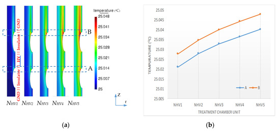
Figure 6.
Simulation results for (a) the liquid temperature along the z-axis and (b) the liquid temperatures at positions A and B.
3.2. Electrical Characteristics of PEF During the Treatment Process
During the PEF treatment process, the electrical characteristics were monitored. For all the experimental conditions, except the no-load treatment condition, a 7.5 kV applied voltage was set at the HVDC source, and the current from the power source was 0.81 mA. Under this operating condition, the specific energy would be 43.93 kJ/kg, approximately [3,13,32]. Figure 7a,b show the pulsed voltage and current waveforms across the treatment chamber during the PEF treatment. As presented in Figure 7a, the high voltage pulses were around 5.91 kV for the no-load treatment condition (measured across the output terminal of the HV switch without the treatment chamber). This implied that there was a large voltage drop in the system, which was in the part before the HV switch, of almost 1.59 kV. This is because a large ballast resistor used for the current limitations causes a large voltage drop across it. Moreover, the voltage drop would possibly be due to the small leakage current through the parasitic elements in the treatment system. However, this leakage current was very small and undetectable with a shunt resistor. It could be noticed that the average voltage pulses decreased as the number of the treatment chambers increased. The average voltage pulses, across the treatment chambers, were 2.30, 1.65, and 1.42 kV for NHV1 NHV2, and NHV3, respectively. As presented in Figure 7b, the current pulses were generated through the conductive liquid media during the existence of voltage pulses. The magnitude of the average current pulses had an opposite trend to that of the voltage pulses, which were 0.95, 2.23, and 5.18 A for NHV1 NHV2, and NHV3, respectively.
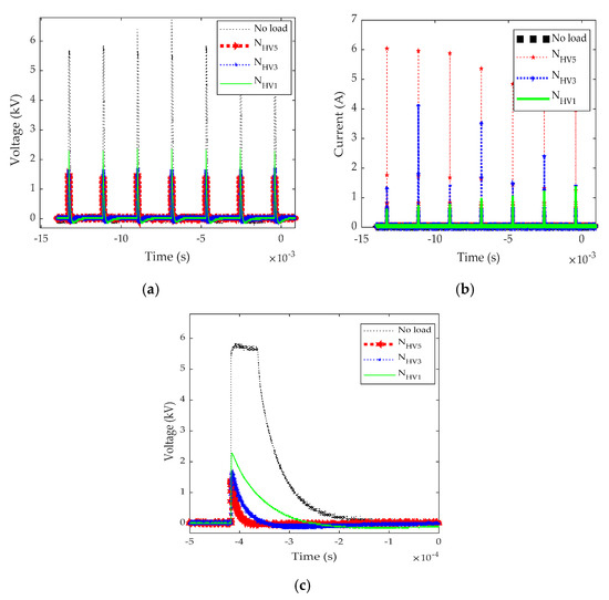
Figure 7.
Electrical characteristics of (a) pulsed voltages, (b) pulsed currents, and (c) voltage waveforms for various conditions.
Figure 7c presents the waveform of a single voltage pulse across the treatment chamber. It could be noticed that the pulse voltage in the no-load treatment condition was almost constant, around 5.91 kV, with a pulse width of around 75 µS. Meanwhile, in other conditions, the pulsed voltage rapidly decreased with different discharge times corresponding to the number of the treatment chambers. As the liquid medium bridges the high voltage and ground electrodes, it hence acts as a liquid resistor. A series of treatment zones causes a parallel connection of the liquid resistors since the treatment chambers have common high voltage and ground electrodes. Therefore, the increase in the treatment zones increases the number of current flowing paths. Consequently, the more treatment units there are, the faster the discharge time. This factor explains the characteristics of the pulsed voltage magnitude, which dropped across multiple electrode units.
3.3. Effect of the Number of Treatment Chambers on E. coli Inactivation
After the PEF treatment process, the treated E. coli suspension from every condition was incubated by the drop plating method for 18 h on a standard agar culture plate for viable cell counting. The temperature change of the treated E. coli suspension was unnoticeable with the thermometer. The temperature was the same as the room temperature (25 °C), which is consistent with the simulation results. This would be due to the fact that the treated solution has dissipated accumulated thermal energy through the long outlet metal ground electrode.
Figure 8a presents the average E. coli colony count. The viable cells of the control group were around 1.7 × 10¹⁰ CFU/mL, while the average viable cells of other conditions were around 6.99 × 10⁷–2.57 × 10⁸ CFU/mL. From the statistically analysis by ANOVA, it could be confirmed that the E. coli were significantly reduced (p < 0.05) in every condition, as shown on a log scale in Figure 8b. The average E. coli log reduction was 1.82, 2.25, and 2.39 for NHV1, NHV3, and NHV5, respectively. The average E. coli inactivation efficiencies showed the same trend for every repeated experiment.
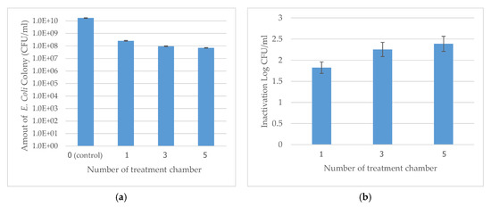
Figure 8.
Results from the different numbers of high voltage (HV) electrodes. (a) Amount of Escherichia coli (E. coli) colony, and (b) E. coli log reduction.
From the experimental results, it could be confirmed that an increase in the number of treatment zones could increase the efficiency of E. coli inactivation. The average E. coli log reduction of NHV3 and NHV5 was higher than that of NHV1 by a factor of 1.24 and 1.31, respectively. This would owe to the fact that increasing the number of treatment chamber units increases the possibility for E. coli to be inactivated by electroporation. Regarding the treatment condition, as E. coli pass the treatment zone, they could possibly be subjected to the high electric field for 75 pulses, for a 7.5 ms duration. Since a treatment unit has two treatment zones, E. coli were hence treated twice. Therefore, for n treatment units, E. coli would be subjected to the high electric field for 150 × n pulses.
However, the increase in the treatment units decreases the energy per pulse since the resistance of the liquid resistors is reduced due to the increase in parallel liquid resistors. This reason results in the voltage drops in contrast to the pulsed current across the treatment chamber, as shown in Figure 7. Since the treated medium is conductive, this fact possibly contributes, to a certain degree, to the joule heating during the treatment process. Moreover, from the simulation results (data not shown here), it is found that a serial connection of the treatment units increases the liquid flow velocity near the surface of the elliptical insulators. This is due to the fact that the diameter of the fluid path is narrower at the treatment zone; therefore, the liquid flow velocity is affected by variation of the tube volume, as described by the equation of continuity [13,14,22,28,33]. This effect influences the treatment efficiency since the liquid flows faster at the treatment zone and is then subjected to decrease in treatment time. Therefore, the time for which the E. coli are subjected to a high electric field is shorter than expected, causing efficiency reduction. Another issue of concern is that the number of series treatment units should also be optimized, since the temperature rise in the treatment zone increases with an increase in treatment units, as shown in the simulation results in Figure 6. However, regarding the hypothesis of this research and the experimental results, it could be confirmed that a proper increase in the number of treatment chambers can improve the efficiency of microbial inactivation. Only a short treatment time (milliseconds) efficiently reduces the number of viable E. coli colonies, which can save processing time compared with the convention PEF treatment process, which requires a re-treatment process as a cycle with extended processing time [2,7,14,17,19,29,34,35,36].
The current research has proposed a novel PEF treatment system, which lays a critical foundation for the method of PEF for microorganism inactivation. In addition, the results from the research could also have an application to processes for agricultural products, not limited to inactivation or shelf-life extension. However, regarding the aforementioned weakness issues in this study, further elaboration is necessary. A possibility to overcome the drawbacks of the proposed system, which is a further detailed study, would be using a very short high voltage pulse in the nanosecond range with a higher frequency to decrease the energy loss in the conductive liquid media. The separation of a serial connection of multiple treatment chambers with a separating high voltage power source would be another prospect to reduce the difference in flow velocity and shared energy per pulse, which cause a decrease in the treatment efficiency.
4. Conclusions
Analytical and experimental studies on the parameters of pulsed electric fields (PEF) for the treatment of Escherichia coli (E. coli) suspensions in a flow-through system were presented. With the optimized co-field type with an elliptic insulator treatment chamber, the treatment zone volume was 83.13 mm3, approximately; the maximum and average electric field intensity at the treatment zone could be as high as 12.66 and 12.21 kV/cm at the moderate 7.5 kV from the HVDC power supply, respectively. Accumulated heat in the flowing liquid media during the treatment process resulted in temperature rises in the liquid media, mainly located slightly behind the elliptic insulator along the flow-through direction. However, in this work, the temperature rise was not significantly increased. It was found from the verified experiments that an increase in the treatment units increased the inactivation efficiency for the E. coli suspension. The average E. coli log reduction was improved by 1.24 and 1.31 times, when the number of treatment units was increased from 1 to 3 and 5, respectively. This owes to the fact that an increase the number of treatment chamber units increases the possibility for E. coli to be inactivated by electroporation. However, the number of treatment units should be optimized together with the treatment chamber geometry and treatment parameters, since the energy per pulse would be decreased due to joule heating in a series of the treatment chambers.
Author Contributions
Conceptualization, K.M. and B.T.; Formal analysis, K.M.; Investigation, K.M. and P.B.; Methodology, K.M. and B.T.; Project administration, K.M.; Resources, P.B.; Writing—original draft, K.M.; Writing—review & editing, K.M. and B.T. All authors have read and agreed to the published version of the manuscript.
Funding
This work was supported by the Thailand Research Fund (TRF) Grant for New Researcher (MRG6180201).
Acknowledgments
The authors would like to thank the department of electrical engineering, engineering faculty, and department of health promotion, faculty of physical therapy, Srinakharinwirot University for the supporting facilities.
Conflicts of Interest
The authors declare no conflict of interest.
References
- Pakhomov, A.G.; Miklavcic, D.; Markov, M.S. Advanced Electroporation Techniques in Biology and Medicine; CRC Press: Boca Raton, FL, USA, 2010. [Google Scholar]
- Marcela Gongora-Nieto, M.; Swanson, B.; Barbosa-Canovas, G.; Vega-Mercado, H. Pulsed Electric Fields in Food Preservation; Elsevier: Amsterdam, The Netherlands, 2007; pp. 783–813. [Google Scholar]
- Timmermans, R.A.H.; Mastwijk, H.C.; Berendsen, L.B.J.M.; Nederhoff, A.L.; Matser, A.M.; Van Boekel, M.A.J.S.; Nierop Groot, M.N. Moderate intensity Pulsed Electric Fields (PEF) as alternative mild preservation technology for fruit juice. Int. J. Food Microbiol. 2019, 298, 63–73. [Google Scholar] [CrossRef]
- Dziadek, K.; Kopeć, A.; Dróżdż, T.; Kiełbasa, P.; Ostafin, M.; Bulski, K.; Oziembłowski, M. Effect of pulsed electric field treatment on shelf life and nutritional value of apple juice. J. Food Sci. Technol. 2019, 56, 1184–1191. [Google Scholar] [CrossRef] [PubMed]
- Palaniappan, S.; Sastry, S.K. Electrical conductivity of selected juices: Influences of temperature, solids content, applied voltage, and particle size. J. Food Process Eng. 1991, 14, 247–260. [Google Scholar] [CrossRef]
- Sharma, P.; Oey, I.; Bremer, P.; Everett, D.W. Microbiological and enzymatic activity of bovine whole milk treated by pulsed electric fields. Int. J. Dairy Technol. 2018, 71, 10–19. [Google Scholar] [CrossRef]
- Barba, F.J.; Parniakov, O.; Pereira, S.A.; Wiktor, A.; Grimi, N.; Boussetta, N.; Saraiva, J.A.; Raso, J.; Martin-Belloso, O.; Witrowa-Rajchert, D.; et al. Current applications and new opportunities for the use of pulsed electric fields in food science and industry. Food Res. Int. 2015, 77, 773–798. [Google Scholar] [CrossRef]
- Vorobiev, E.; Lebovka, N. Applications of Pulsed Electric Energy for Biomass Pretreatment in Biorefinery; Elsevier Inc.: Amsterdam, The Netherlands, 2016; pp. 151–168. [Google Scholar]
- Zimmermann, U.; Pilwat, G.; Riemann, F. Dielectric Breakdown of Cell Membranes. In Membrane Transport in Plants; Ulrich, Z., Jack, D., Eds.; Springer: Berlin/Heidelberg, Germany, 1974; pp. 146–153. [Google Scholar]
- Mussatto, S.I. Biomass Fractionation Technologies for a Lignocellulosic Feedstock Based Biorefinery; Elsevier: Amsterdam, The Netherlands, 18 February 2016. [Google Scholar]
- Benz, R.; Zimmermann, U. Pulse-length dependence of the electrical breakdown in lipid bilayer membranes. Biochim. Biophys. Acta-Biomembr. 1980, 597, 637–642. [Google Scholar] [CrossRef]
- Murakami, Y.; Muramoto, Y.; Shimizu, N. Influence of ion concentration in aqueous solution on sterilization of E. coli by high electric field pulse. In Proceedings of the IEEE Conference on Electrical Insulation and Dielectric Phenomena (CEIDP), Des Moines, IA, USA, 19–22 October 2014; pp. 228–231. [Google Scholar] [CrossRef]
- Meneses, N.; Jaeger, H.; Moritz, J.; Knorr, D. Impact of insulator shape, flow rate and electrical parameters on inactivation of E. coli using a continuous co-linear PEF system. Innov. Food Sci. Emerg. Technol. 2011, 12, 6–12. [Google Scholar] [CrossRef]
- Salengke, S.; Sastry, S.K.; Zhang, H.Q. Pulsed electric field technology: Modeling of electric field and temperature distributions within continuous flow PEF treatment chamber. Int. Food Res. J. 2012, 19, 1137–1144. [Google Scholar]
- Fiala, A.; Wouters, P.C.; Van den Bosch, E.; Creyghton, Y.L.M. Coupled electrical-fluid model of pulsed electric field treatment in a model food system. Innov. Food Sci. Emerg. Technol. 2001. [Google Scholar] [CrossRef]
- Barba, F.J.; Koubaa, M.; do Prado-Silva, L.; Orlien, V.; Sant’Ana, A.D.S. Mild processing applied to the inactivation of the main foodborne bacterial pathogens: A review. Trends Food Sci. Technol. 2017, 66, 20–35. [Google Scholar] [CrossRef]
- Chemat, F.; Rombaut, N.; Meullemiestre, A.; Turk, M.; Perino, S.; Fabiano-Tixier, A.S.; Abert-Vian, M. Review of Green Food Processing techniques. Preservation, transformation, and extraction. Innov. Food Sci. Emerg. Technol. 2017, 41, 357–377. [Google Scholar] [CrossRef]
- Mohamed, M.E.; Amer Eiss, A.H. Pulsed Electric Fields for Food Processing Technology. In Structure and Function of Food Engineering; Eiss, A.A., Ed.; IntechOpen: London, UK, 2012; Volume 11, pp. 275–306. [Google Scholar]
- Raso, J.; Frey, W.; Ferrari, G.; Pataro, G.; Knorr, D.; Teissie, J.; Miklavčič, D. Recommendations guidelines on the key information to be reported in studies of application of PEF technology in food and biotechnological processes. Innov. Food Sci. Emerg. Technol. 2016, 37, 312–321. [Google Scholar] [CrossRef]
- Masood, H.; Diao, Y.; Cullen, P.J.; Lee, N.A.; Trujillo, F.J. A comparative study on the performance of three treatment chamber designs for radio frequency electric field processing. Comput. Chem. Eng. 2018, 108, 206–216. [Google Scholar] [CrossRef]
- Kandušer, M.; Belič, A.; Čorović, S.; Škrjanc, I. Modular Serial Flow Through device for pulsed electric field treatment of the liquid samples. Sci. Rep. 2017, 7, 1–12. [Google Scholar] [CrossRef]
- Kriengkriwut, T.; Techaumnat, B. Simulation of Electric Field in Co-Field Treatment Chamber Using FEM. Appl. Mech. Mater. 2015, 781, 612–615. [Google Scholar] [CrossRef]
- Jan, A.; Sood, M.; Sofi, S.A.; Norzom, T. Non-thermal processing in food applications: A review. Int. J. Food Sci. Nutr. 2017, 2, 171–180. [Google Scholar]
- Pyatkovskyy, T.I.; Shynkaryk, M.V.; Mohamed, H.M.; Yousef, A.E.; Sastry, S.K. Effects of combined high pressure (HPP), pulsed electric field (PEF) and sonication treatments on inactivation of Listeria innocua. J. Food Eng. 2018, 233, 49–56. [Google Scholar] [CrossRef]
- Zhang, Z.H.; Wang, L.H.; Zeng, X.A.; Han, Z.; Brennan, C.S. Non-thermal technologies and its current and future application in the food industry: A review. Int. J. Food Sci. Technol. 2019, 54, 1–13. [Google Scholar] [CrossRef]
- Puértolas, E.; Luengo, E.; Álvarez, I.; Raso, J. Improving Mass Transfer to Soften Tissues by Pulsed Electric Fields: Fundamentals and Applications. Annu. Rev. Food Sci. Technol. 2012, 3, 263–282. [Google Scholar] [CrossRef]
- Ricci, A.; Parpinello, G.P.; Versari, A. Recent Advances and Applications of Pulsed Electric Fields (PEF) to Improve Polyphenol Extraction and Color Release during Red Winemaking. Beverages 2018, 4, 18. [Google Scholar] [CrossRef]
- Kriengkriwut, T. Numerical Study of the Geometrical and Electrical Parameters for the Pulsed Electric Field (PEF) Treatment. Master’s Thesis, Chulalongkorn University, Bangkok, Thailand, 2015. [Google Scholar]
- Hui, Y.H.; Culbertson, J.D.; Duncan, S.E.; Legarreta, I.G.; Li-Chan, E.C.Y.; Ma, C.Y.; Manley, C.; McMeekin, T.; Nip, W.K.; Nollet, L.M.L.; et al. Handbook of Food Science, Technology, and Engineering; CRC Press: Boca Raton, FL, USA, 2006. [Google Scholar]
- Schroeder, S.; Buckow, R.; Knoerzer, K. Numerical simulation of pulsed electric fields (PEF) processing for chamber design and optimisation. In Proceedings of the 17th International Conference on CFD in the Minerads and Process Industries CSIRO, Melbourne, Australia, 9–11 December 2009. [Google Scholar]
- Knoerzer, K.; Baumann, P.; Buckow, R. An iterative modelling approach for improving the performance of a pulsed electric field (PEF) treatment chamber. Comput. Chem. Eng. 2012, 37, 48–63. [Google Scholar] [CrossRef]
- Buchmann, L.; Böcker, L.; Frey, W.; Haberkorn, I.; Nyffeler, M.; Mathys, A. Energy input assessment for nanosecond pulsed electric field processing and its application in a case study with Chlorella vulgaris. Innov. Food Sci. Emerg. Technol. 2018, 47, 445–453. [Google Scholar] [CrossRef]
- Kaur, K.; Annus, I.; Vassiljev, A.; Kändler, N. Determination of Pressure Drop and Flow Velocity in Old Rough Pipes. Proceedings 2018, 2, 590. [Google Scholar] [CrossRef]
- Wouters, P.C.; Dutreux, N.; Smelt, J.P.P.M.; Lelieveld, H.L.M. Effects of pulsed electric fields on inactivation kinetics of Listeria innocua. Appl. Environ. Microbiol. 1999, 65, 5364–5371. [Google Scholar] [CrossRef] [PubMed]
- Raso, J.; Barbosa-Cánovas, G.V. Nonthermal Preservation of Foods Using Combined Processing Techniques. Crit. Rev. Food Sci. Nutr. 2003, 43, 265–285. [Google Scholar] [CrossRef] [PubMed]
- Boziaris, I.S. Novel Food Preservation and Microbial Assessment Techniques; CRC Press: Boca Raton, FL, USA, 2014. [Google Scholar]
© 2020 by the authors. Licensee MDPI, Basel, Switzerland. This article is an open access article distributed under the terms and conditions of the Creative Commons Attribution (CC BY) license (http://creativecommons.org/licenses/by/4.0/).