Article

Verification of Optimized Real-time Hybrid Control System for Prediction of Nonlinear Materials Behavior with 3-DOF Dynamic Test

1
R&D Division, Hyundai E&C, Gyeonggi-do 14102, Korea
2
Department of Civil Engineering, College of Engineering, Chonnam National University, Gwangju 61186, Korea
*
Author to whom correspondence should be addressed.
Appl. Sci. 2020, 10(11), 4037; https://doi.org/10.3390/app10114037
Submission received: 16 April 2020 / Revised: 28 May 2020 / Accepted: 4 June 2020 / Published: 11 June 2020

Abstract

:
Real-time hybrid method is an economical and efficient test method to evaluate the dynamic behavior. The purpose of this study is to develop the computational algorithm and to prove the reliability of a real-time hybrid control system. For performing the multi-direction dynamic test, three dynamic actuators and the optimized real-time hybrid system with new hybrid simulation program (FEAPH) and a simplified inter-communication were optimized. To verify the reliability and applicability of the real-time hybrid control system, 3-DOF (3 Degrees of Freedom) non-linear dynamic tests with physical model were conducted on a steel and concrete frame structure. As a ground acceleration, El Centro and Northridge earthquake waves were applied. As a result, the maximum error of numerical analysis is 13% compared with the result of shaking table test. However, the result of real-time hybrid test shows good agreement with the shaking table test. The real-time hybrid test using FEAPH can make good progress on the total testing time and errors. Therefore, this test method using FEAPH can be effectively and cheaply used to evaluate the dynamic performance of the full-scale structure, instead of shaking table and full-scale test.

1. Introduction

The dynamic test method of earthquake-loaded structural systems has been developed for more accurately assessment. These methods are largely classified into numerical methods and experimental methods. In the numerical method, the structural system can be represented by the discretized motion equations and the solution is obtained to evaluate the dynamic characteristics of the structure. However, there are limitations on the diversity and accuracy of material models for structures, and several types of numerical time integration methods have been developed and used to date. Compared to the numerical method, the experimental methods, such as pseudo-dynamic tests and shaking table tests, can be more direct in evaluating the dynamic elastic properties of structures relatively effectively, but it is expensive and may require huge experimental facilities depending on the experiment [1]. Additionally, it is difficult to repeat the same test using a shake table due to the cost of manufacturing the specimen.
To overcome these shortcomings, the real-time hybrid test (RTHT) has been actively studied by many researchers [2,3,4,5,6,7,8,9,10,11,12,13,14,15,16,17,18,19,20,21,22,23,24,25,26,27]. The real-time hybrid test method is one of the less expensive and more efficient methods compared to the shaking table test and allows you to evaluate the dynamic characteristics of the structure with high accuracy.
The early concept of the hybrid testing was initiated from a pseudo-dynamic test simulating seismic loads using one actuator to predict the nonlinear behavior of structures in the 1960s [2,3]. In the 1980s, theoretical studies of the pseudo-dynamic test were established [4,5].
After started by Nakashima and the real-time hybrid test were developed with special programs such as OpenSees and OpenFresco [6,7,8,9,10,11]. As a part of NEES (Network for Earthquake Engineering Simulation) project, Jung et al. tried something new to fix the iteration numbers for the convergence error and designed the optimum algorithm for the real-time hybrid test with 1 DOF (Degree of Freedom) and 2-DOF models [12]. Bonnet also developed the multi-degree of freedom real-time hybrid testing with various numerical scheme [13]. Lately, Abbiati et al. focused on the quality of the simulation strongly depending on the correct application of the interface boundary conditions between the numerical and the physical subdomains with eight actuators [14]. In order to evaluate the seismic performance for a twelve-story precast reinforced concrete shear-wall structure, Chen et al. employed the full-scale bottom structural model as the physical substructure and the elastic non-linear model as the numerical substructure and used an equivalent force control method [15]. Kang et al. and Saouma et al. have conducted the real-time hybrid test for concrete structures after developing Mercury with optimized computer environment for numerical analysis and hardware [16,17]. For the dynamic performance of bridge structures, the hybrid test with seismic proactive system such as viscous damper and isolators has been conducted by many researchers [18,19,20,21]. Recently, mooring system of offshore structure was applied with real-time hybrid test method [22].
Chang et al. developed a robust standardized procedure for hybrid testing of a multi-span bridge through internet between Canada and Taiwan [23]. Recently, Bousias et al. tried to carry out hybrid simulations of a three-span reinforced concrete bridge among EU, US, and Canada [24]. The tests involved partners located on both sides of the Atlantic with each one assigned a numerical or a physical module of the substructured bridge. Despite the network latency in linking remote sites, the intercontinental hybrid simulation was accomplished and repeated successfully, highlighting the efficiency, and repetitiveness of the approach.
In Korea, several real-time hybrid tests using physical steel models have been performed, but the application of the test method is still one of the research topics [25,26,27]. Therefore, many studies of appropriate computational algorithms related to hybrid testing control configuration have been attempted to demonstrate the effectiveness and reliability of the real-time hybrid test.
The main purpose of this study is to verify the reliability of the simplified real-time hybrid control system and a nonlinear finite element analysis program for investigating the dynamic characteristics of structures with nonlinear materials. To verify the accuracy and stability of the performance of the real-time hybrid control system, various numerical simulations and real-time hybrid dynamic tests were conducted on steel and concrete frame structures.
First of all, the configuration of the simplified RTHT control system and the developed FEM (Finite Element Method) program, called FEAPH (Finite Element Analysis Program for Hybrid test), were demonstrated. Next, the accuracy of control system was proven through the 3-DOF linear dynamic test with steel frame. Finally, the reliability of RTHT was investigated with 3-DOF (3 Degrees of Freedom) nonlinear dynamic tests with steel and concrete frame structures.

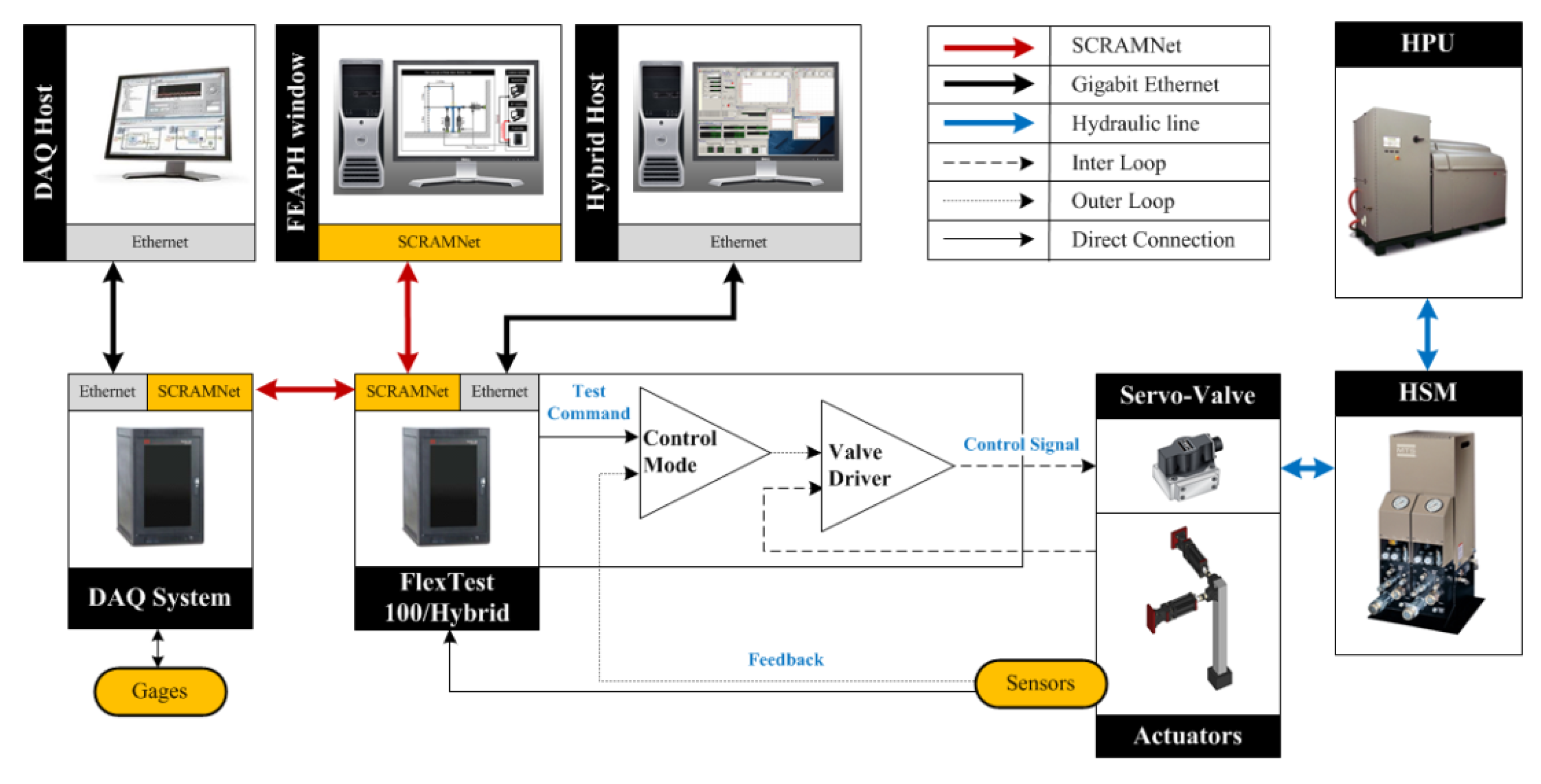
2. Configuration of the Hybrid Test Hardware

The overall flow chart of the RTHT (Real-Time Hybrid Test) system used in this study is shown in Figure 1. It consists of three areas: FEAPH window, Flextest, and DAQ (Data acquisition). These three areas are connected to a shared common RAM network (SCRAMNet) to share data in real time. The FEAPH window is the area where the finite element program is implemented, and the analysis results are stored directly in SCRAMNet. The results stored in SCRAMNet provide real-time testing by providing command displacement to the actuator via Flextest and sharing the feedback values obtained from the displacement meter and load cell via SCRAMNet. The system is configured so that the results obtained in each system area can be intercommunicated almost simultaneously using shared memory (SCRAMNet). In order to run this optimized real-time hardware system, the company developed and executed a dedicated analysis program for the hybrid system in the FEAPH window. The FEAPH program includes the algorithm of what Simulink has so that the program can run tests without any additional execution processes.
Three WorkStation T5400 (2.33GHz quad-core, 1GB RAM) devices manufactured by Dell International (Round Rock, TX, USA) were used for the system. High frequency dynamic performance is optimized using dynamic actuators (250 kN, ± 125 mm). In order to minimize the error value due to the difference between the measured variable and the desired set point, the PID (Proportional-Integral-Derivative) controller algorithm is used.

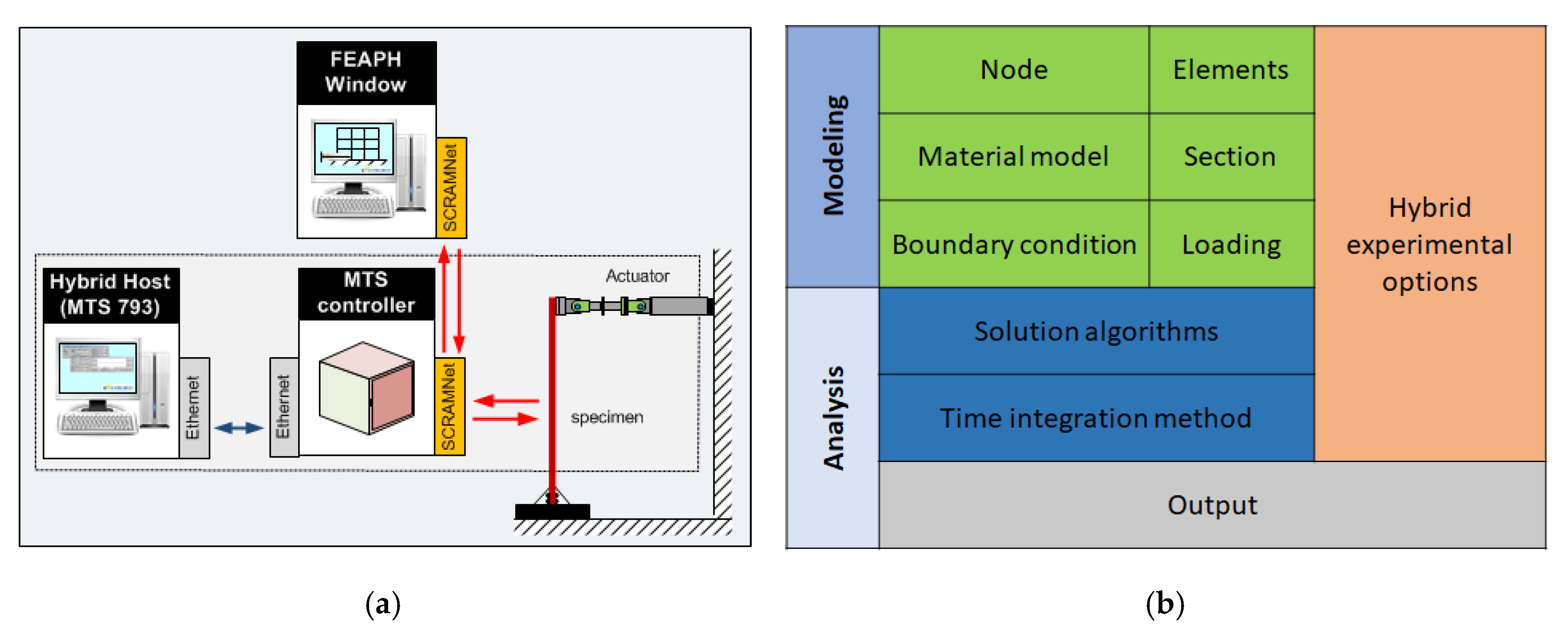
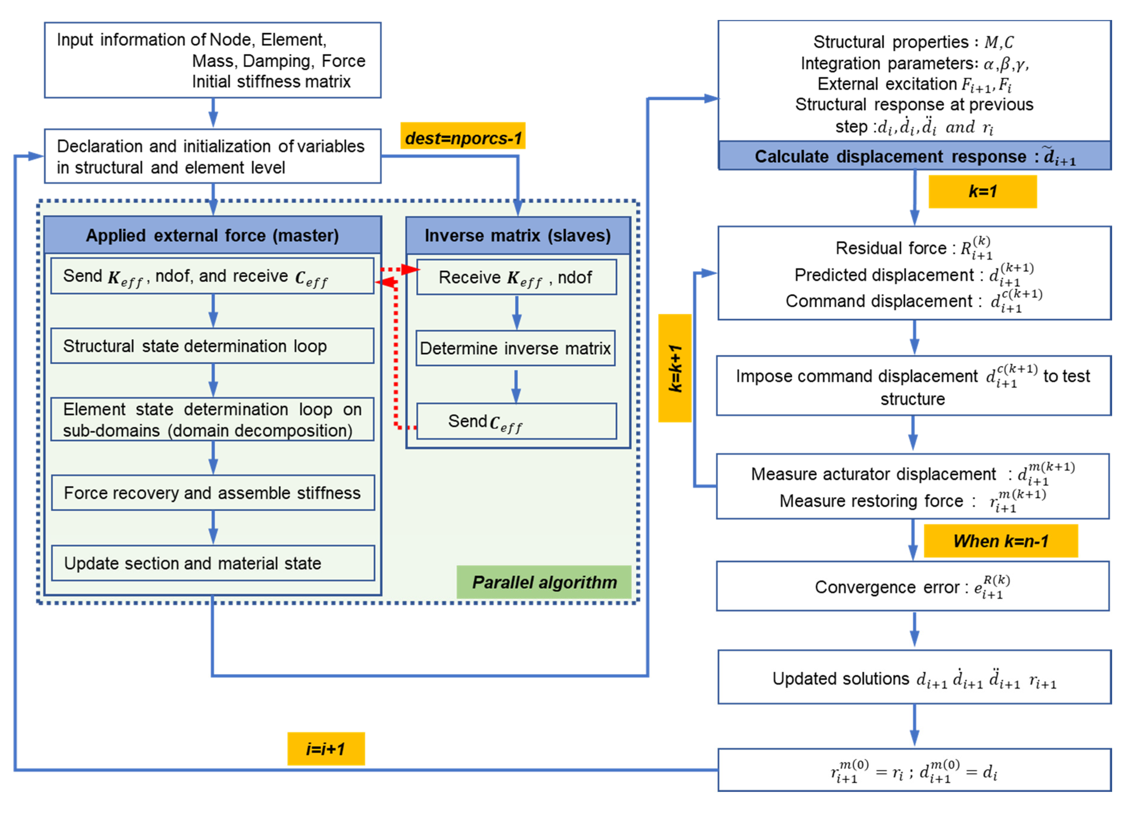
3. Finite Element Analysis Program for Hybrid Testing and Procedures

OpenSees, one of the hybrid testing programs, is most widely used for the RTHT in the world. For the replacement of OpenSees, in this study, FEAPH (Finite Element Analsis Program for Hybrid testing) was developed. As shown in Figure 2a, data communication between commands and responses has been optimized to simplify the test execution process of the analysis program (FEAPH) which is developed in C++ language. The program has several advantages as input file, computation time, and operating system. The Lua scripting language was used because of its portability and small capacity when writing input files. Intel Math Kernel Library optimizes matrix operation by minimizing computation execution time and optimizing parallel scalability with multithreading technology.
The main components of FEAPH consist of two parts; a modeling part and a numerical analysis part, as shown in Figure 2b. The modelling part includes the basic information such as node, section, element, material properties, boundary condition, and loadings. In numerical analysis part, parallel algorithm, and time integration with fixed iteration method are adopted to reduce the computational time for hybrid testing [18].
In real-time hybrid test, it is necessary to minimize the computational time required for numerical analysis. In order to solve the equations of motion numerically, the time integration algorithm is performed at each time step and the command displacement is calculated through an iterative correction process. In particular, the fixed iterative implicit HHT (Hilber-Hughes-Taylor) time integration method is a very efficient method to reduce the repetitive computational time because of a fixed number of convergence error in real-time hybrid test [14,28]. In addition, a parallel algorithm using OpenMP (Open Multi-processing) was adopted to reduce the computational time using a processor that performs only inverse matrix and on the other processors, the information of subdomain elements is assigned [18]. As shown in Figure 3, real-time hybrid numerical algorithms used in FEAPH are demonstrated.

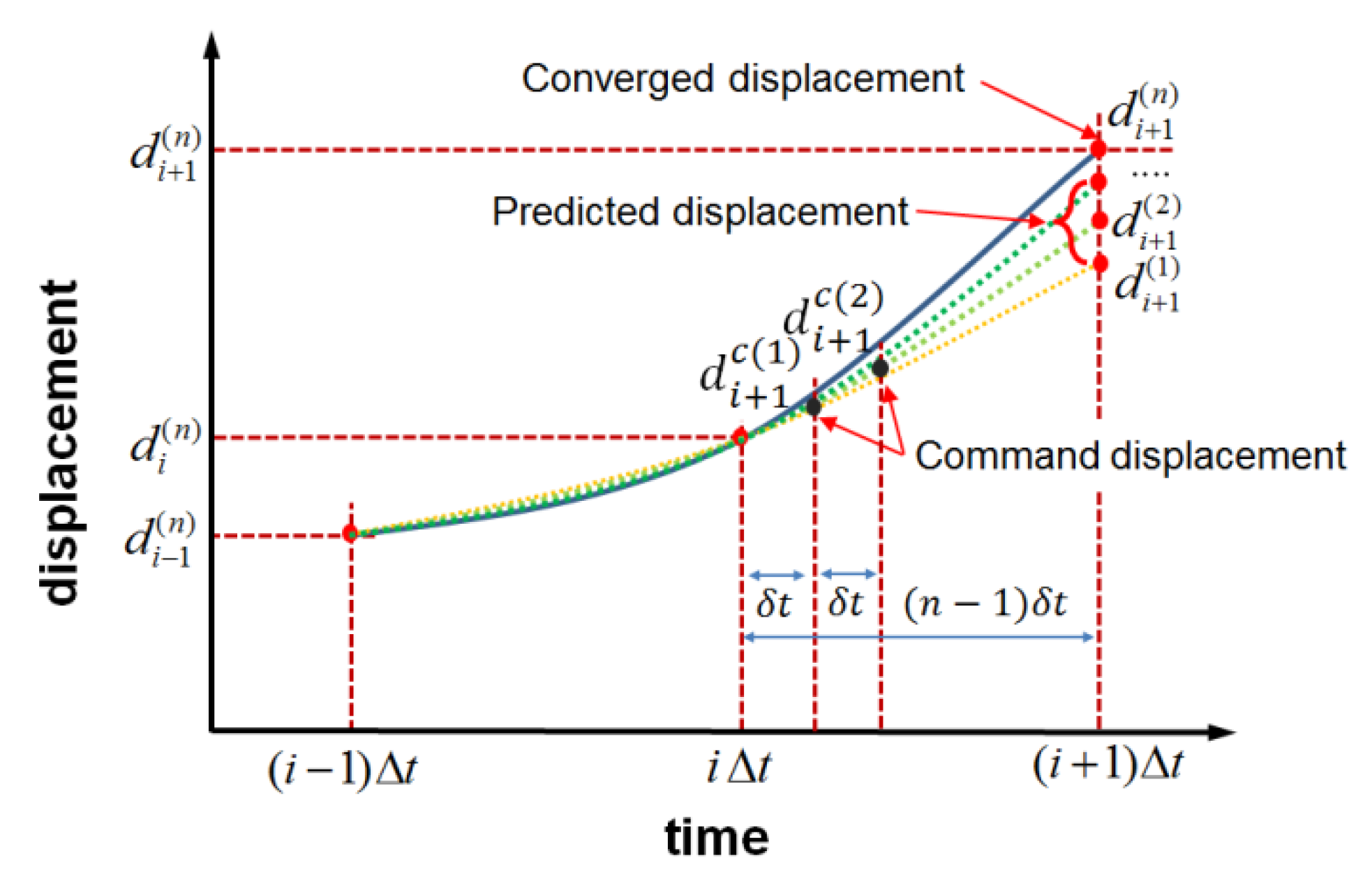
4. Time Integration Method

In the previous section, the HHT time integration method used for reducing the computational time was mentioned and the detailed explanation can be as follows [29,30]:
M a i + 1 + ( 1 + α ) C v i + 1 α C v i + ( 1 + α ) r i + 1 α r i = ( 1 + α ) F i + 1 α F i
d i + 1 = d ˜ i + 1 + Δ t 2 β a i + 1
v i + 1 = v ˜ i + 1 + Δ t γ a i + 1
d ˜ i + 1 = d i + Δ t v i + Δ t 2 ( 1 2 β ) a i
v ˜ i + 1 = v i + Δ t ( 1 γ ) a i
where the integral coefficient 1 3 α 0 ,   β = ( 1 α ) 2 4 ,   γ = 1 2 α .
The restoring force ( r i + 1 ) as a known value can be calculated from the command displacement. At the next time step ( i + 1 ), Equation (1) can be rewritten as below.
M a i + 1 ( k ) + ( 1 + α ) C v i + 1 ( k ) α C v i + ( 1 + α ) r i + 1 ( k ) α r i = ( 1 + α ) F i + 1 α F i R i + 1 ( k )
Equation (6) can be expressed with equation (1) and R i + 1 ( k ) (residual force) can be as follows.
R i + 1 ( k ) = M ( a i + 1 a i + 1 ( k ) ) + ( 1 + α ) C ( v i + 1 v i + 1 ( k ) ) + ( 1 + α ) ( r i + 1 r i + 1 ( k ) )
Equation (7) can be rearranged for Δ d i + 1 ( k ) :
R i + 1 ( k ) = M Δ d i + 1 ( k ) Δ t 2 β + ( 1 + α ) C γ Δ t β + ( 1 + α ) K i n i ,   i + 1 ( k )   Δ d i + 1 ( k ) = K *   Δ d i + 1 ( k )
where K i n i ,   i + 1 ( k )   Δ d i + 1 ( k ) = r i + 1 r i + 1 ( k )   , K * = M ¯ Δ t 2 β + ( 1 + α ) K i n i ,   i + 1 ( k )   , M ¯ = M + ( 1 + α ) C   Δ t   γ .
In Equation (8), the equilibrium equation for Δ d i + 1 ( k ) can be solved because initial stiffness, K i n i and residual force R i + 1 ( k ) are known. Besides, the residual force ( R i + 1 ( k ) ) can be expressed in the predicted displacement (   d i + 1 ( k ) ) and the restoring force ( r i + 1 ( k ) ) and can be shown again in terms of the measured displacement ( d i + 1 m ( k ) ) and measured restoring force ( r i + 1 m ( k ) ) from the real-time hybrid test.
R i + 1 ( k ) = M ¯ Δ t 2 β [ d ˜ i + 1 d i + 1 ( k ) ] + ( 1 + α ) r i + 1 ( k ) = M ¯ Δ t 2 β [ d ˜ i + 1 d i + 1 m ( k ) ] + ( 1 + α ) r i + 1 m ( k )
where d ˜ i + 1 = d ˜ i + Δ t 2 β M ¯ 1 [ ( 1 + α ) F i + 1 α F i C v i ( 1 + α ) ( 1 γ ) Δ t C a i + α r i ] .
The residual force ( R i + 1 ( k ) ) in Equation (9) can be renewed repeatedly and then the predicted displacement ( d i + 1 ( k + 1 ) ) can be updated as below:
  d i + 1 ( k + 1 ) = d i + 1 m ( k ) + Δ   d i + 1 ( k )
For the reduction of errors, the correction of convergence displacement as shown in Figure 4 should confirmed equilibrium state at the end of the iterative process and all displacement, restoring force, velocity, and acceleration, should be updated at the end step as below:
d i + 1 = d i + 1 c ( n )
r i + 1 = r i + 1 m ( n ) + K i n i [ d i + 1 c ( n ) d i + 1 m ( n ) ]
a i + 1 = 1 Δ t 2 β [ d i + 1 d i Δ t v i Δ t 2 ( 1 2 β ) a i ]
v i + 1 = v i + Δ t γ a i + 1 + Δ t ( 1 γ ) a i

5. Verification of Real-time Hybrid Control System

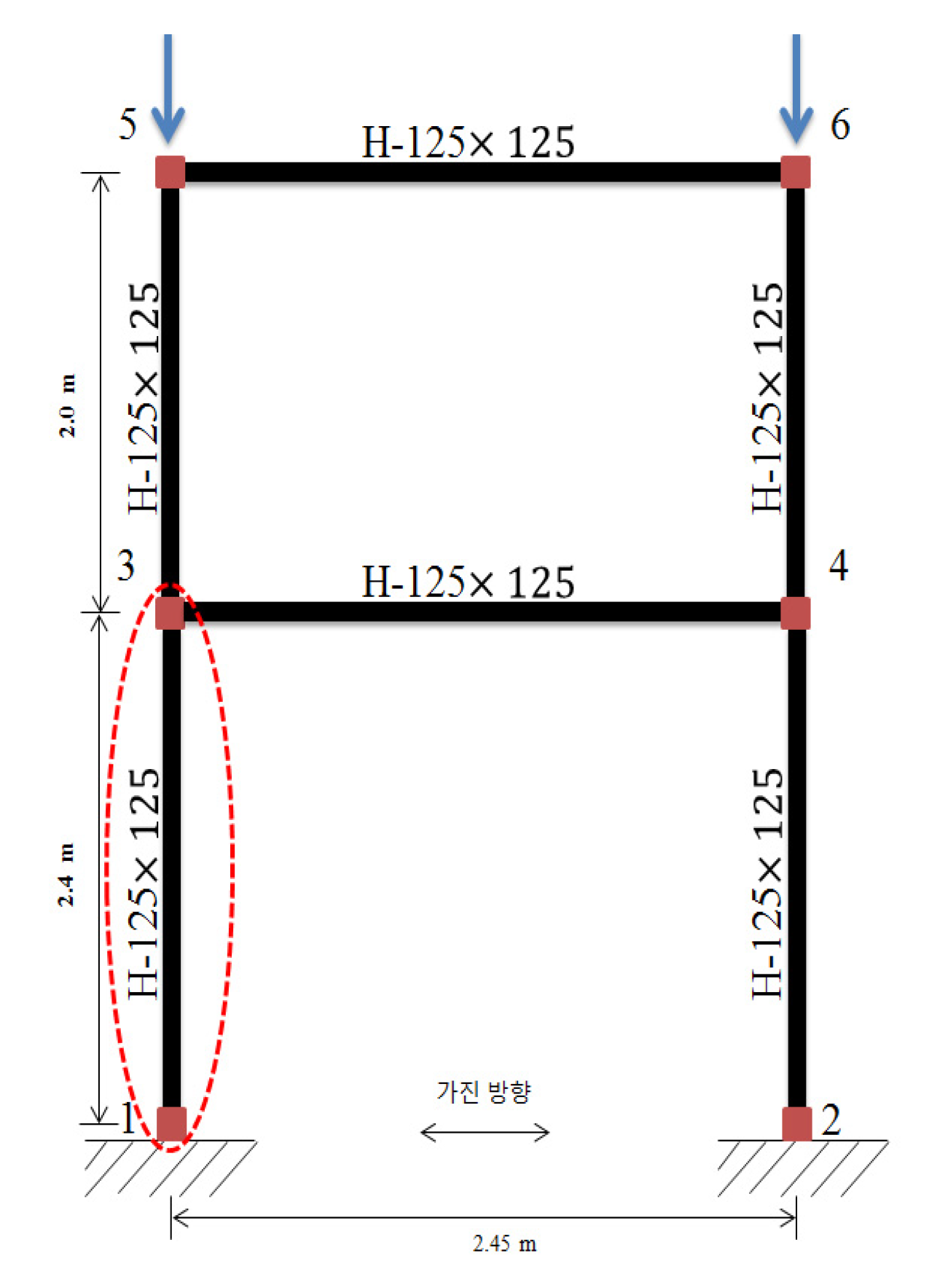
5.1. Three-DOF Structural Dynamic Test with Steel Structure

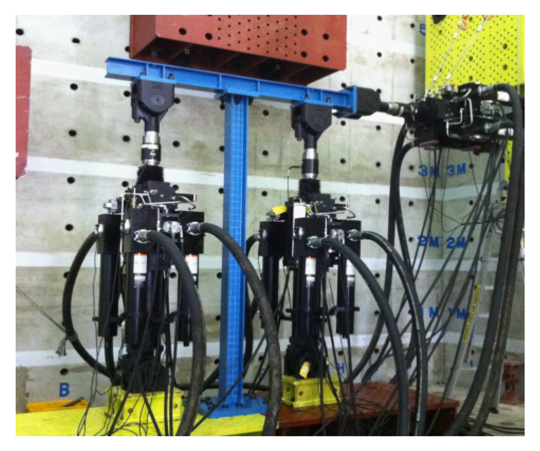
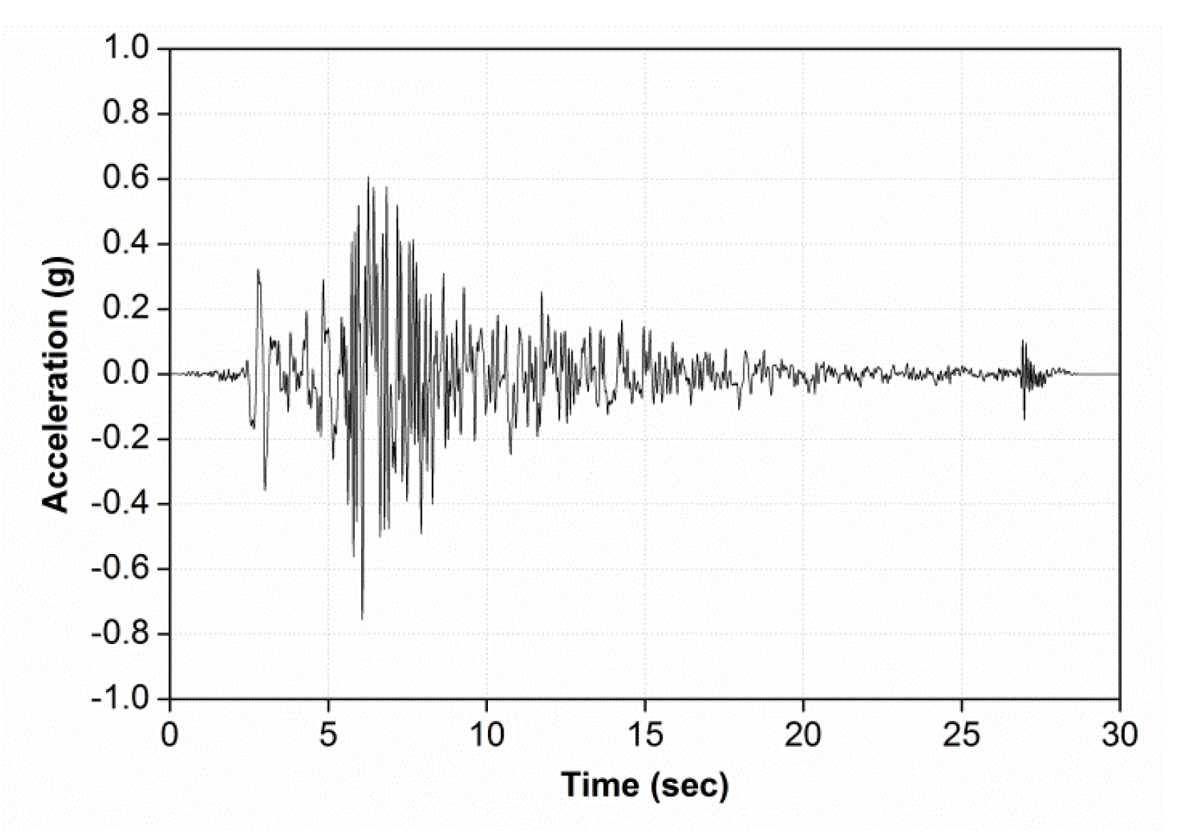
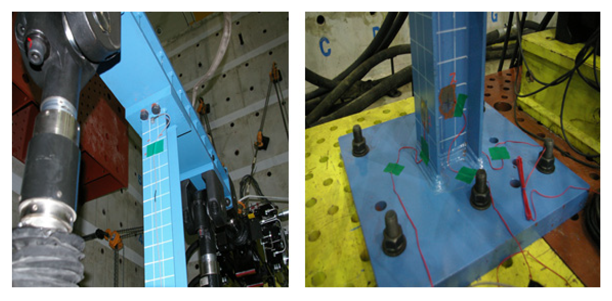
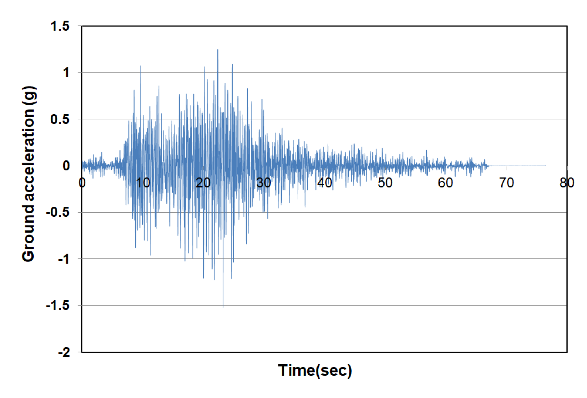
5.1.1. Test Set-Up and Input Properties

To confirm the simplified hybrid test control system, a steel frame specimen, one of the homogeneous materials predicting the nonlinear behavior, was used. As shown in Figure 5, the size of the specimen is 2.45 m wide and the height of the first and second floors is 2.4 m and 2 m, respectively, and a numerical analysis model was constructed with six beam-column elements under the same conditions. As shown in Figure 6, the physical model for the real-time hybrid test was prepared by constructing a column element on the first floor of the numerical model and installing one actuator horizontally and two actuators vertically in order to simulate a displacement and a rotation at the node.
As shown in Figure 7, El Centro seismic wave was applied as the external load, and total loading time is about 30 s and the peak ground acceleration value was 0.7553 g. Figure 8 demonstrated the installation of an accelerometer and strain gauges on the steel frame specimen and Table 1 presented the detail dimension and properties of the specimen [31].
In order to accurately predict the nonlinear behavior of the steel frame specimen during the real-time hybrid testing, the elastic modulus (230 GPa) and yield stress (300 MPa) were measured through a tensile test with universal testing machine (MTS 322), and the Giuffre-Menegotto-Pinto model was used as the nonlinear material model.

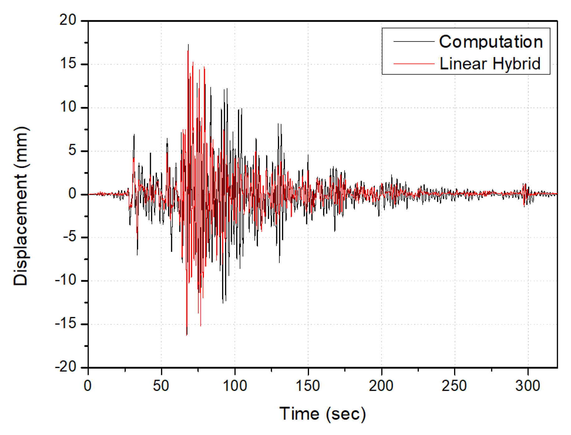
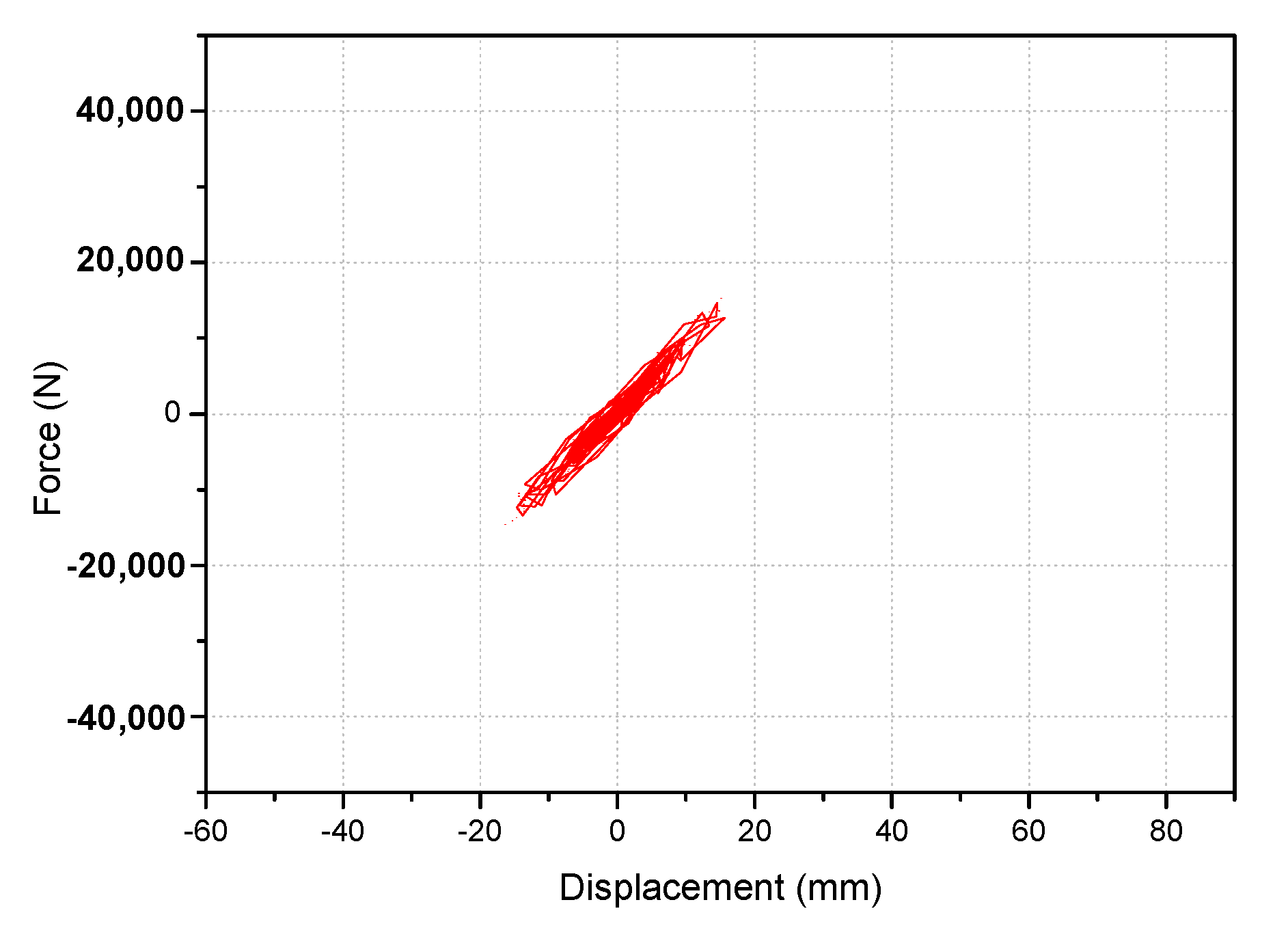
5.1.2. Linear Dynamic Test with Real-Time Hybrid Control System

In this section, real-time hybrid tests were performed by adjusting the PGA (Peak Ground Acceleration) of the input seismic wave (Elcentro) within the linear displacement of the test specimen. The purpose of the linear dynamic tests was to evaluate the accuracy and stability of the overall system by comparing the numerical results with the hybrid test results. As shown in Figure 6, each actuator describes the horizontal and bending displacement at the end of the test specimen, and the response values are reflected in the numerical analysis to derive the results of each step. As a result, as shown in Figure 9, the difference of the maximum displacement between the numerical analysis and the linear hybrid test was found to have almost the same results around 4% error. Figure 10 described the relationship of displacement and force in linear dynamic test. This hybrid system is stable and effective to predict the dynamic behavior of the structure.

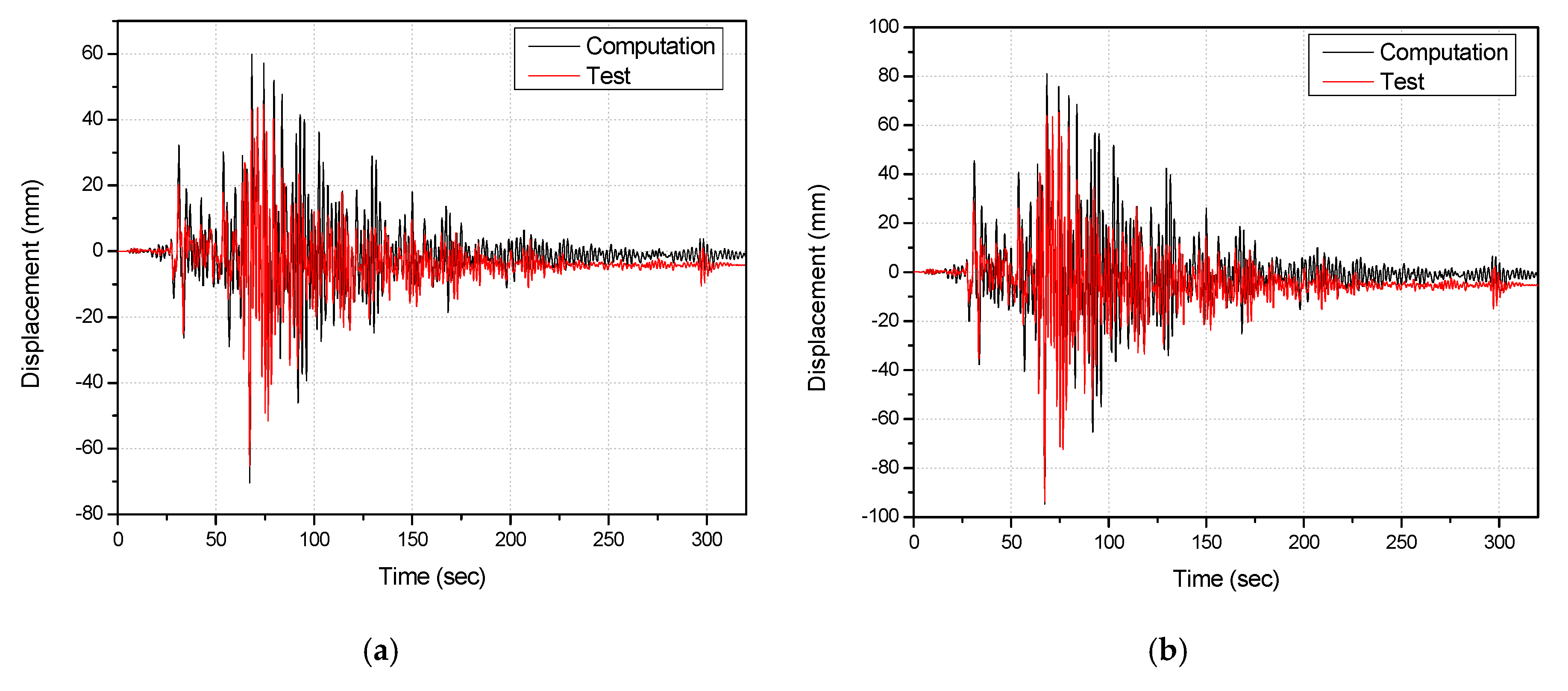
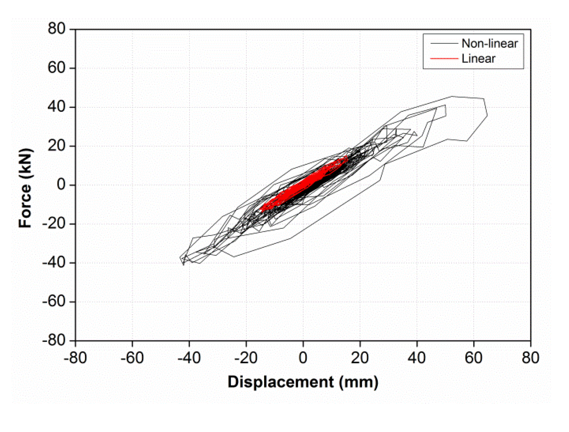
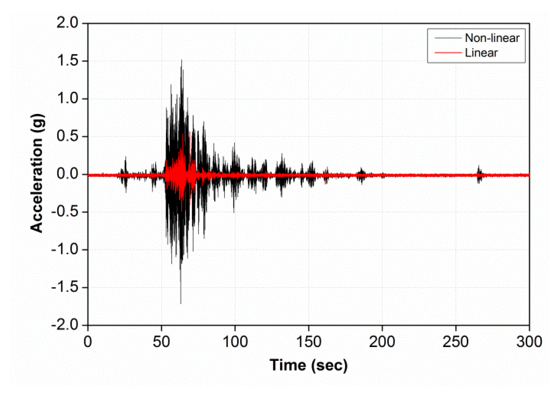
5.1.3. Non-Linear Dynamic Test with Real-Time Hybrid Control System

In this section, a nonlinear test was performed to prove the reliability of the hybrid control system. The magnitude of the incremental coefficient for the nonlinear dynamic test was determined to be larger than the displacement (40.07 mm) to be obtained in the non-linear range by applying yield stress to the cantilever beam of 2.4 m. As a result, the incremental coefficient for seismic load was set to 2 for linear dynamic test and 6 for nonlinear section analysis. Figure 11 showed the results of the first and second layers by the numerical analysis with the hybrid numerical analysis, respectively. The maximum displacement was about 7% and 1% in the 1st and 2nd floors, respectively, and it could be said that the numerical analysis and the experimental data can be in good agreement. In addition, the permanent deformation occurred in the structure after the maximum displacement, it could be seen that the graph was much lowered from the origin after 100 s. After then, a slight difference between displacement and numerical value was observed. This error can be attributed to the damping ratio used in the numerical analysis. The damping ratio of the test specimen is calculated by performing the free vibration test of the test specimen, which includes various errors in the test process and has a limitation on its reliability. In addition, the value used as the material model may include some errors in the nonlinear analysis, and finally, the experimental error between the actuator and the experiment to realize the multiple degree of freedom may be considered. Therefore, if an error reduction is developed more, it may be considered a more reliable experiment.
Figure 12 shows the results of the horizontal displacement and shear force on the first floor, and Figure 13 shows the values measured by the accelerometer on the first floor. As shown in Figure 12, when the maximum displacement of about 60 mm occurs, the load is 40 kN, resulting in residual strain. This shows that the acceleration occurred at 1.7 g as shown in Figure 13. In addition, Figure 14 shows the response history measured by the strain gauge installed at the lower part of the test specimen, and it can be seen that after the maximum displacement, residual deformation occurs in elasticity in both the flange and the web and transfer to plasticity. The permanent strain measured at the flange is about 200–250 μm and about 490 μm on the web. Therefore, it can be inferred that the residual strain generated in the first and second layers is due to the deformation of the end of the test specimen.
As a result of this experiment, in order to predict nonlinear behavior of steel frame structure, it can be grasped through numerical analysis and shaking table test. However, because numerical analysis depends on numerical approximation of the behavior and material properties of the structure, it is difficult to accurately predict the behavior of a complex concrete structure. Therefore, applying real-time hybrid experiments with the advantages of numerical analysis and comparatively spatial and economic advantages, the structural nonlinear behavior analysis can be performed efficiently.

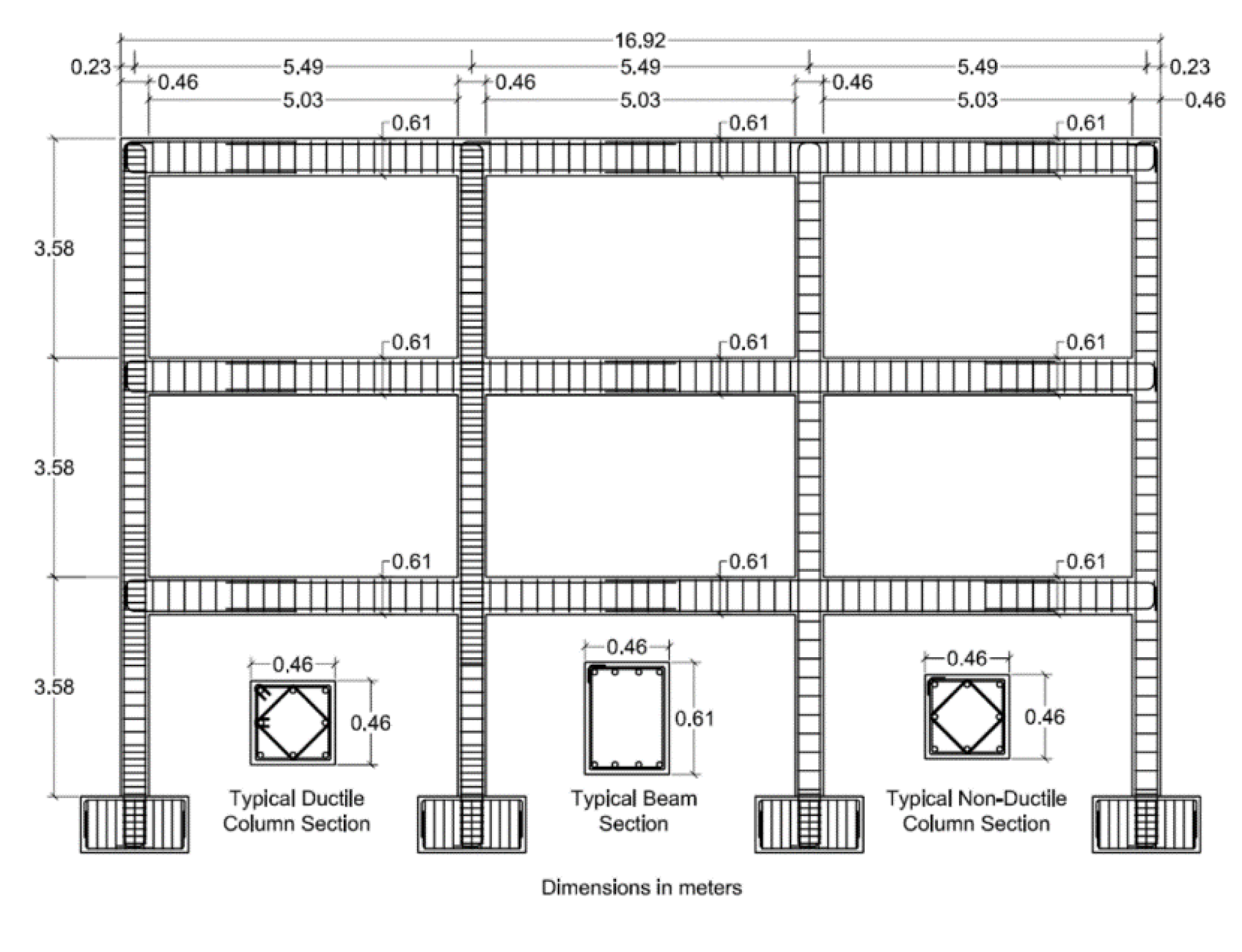
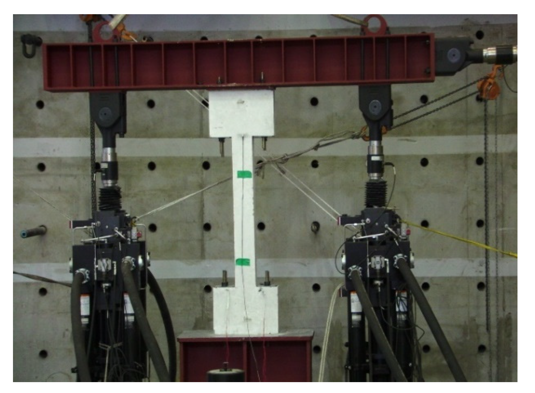
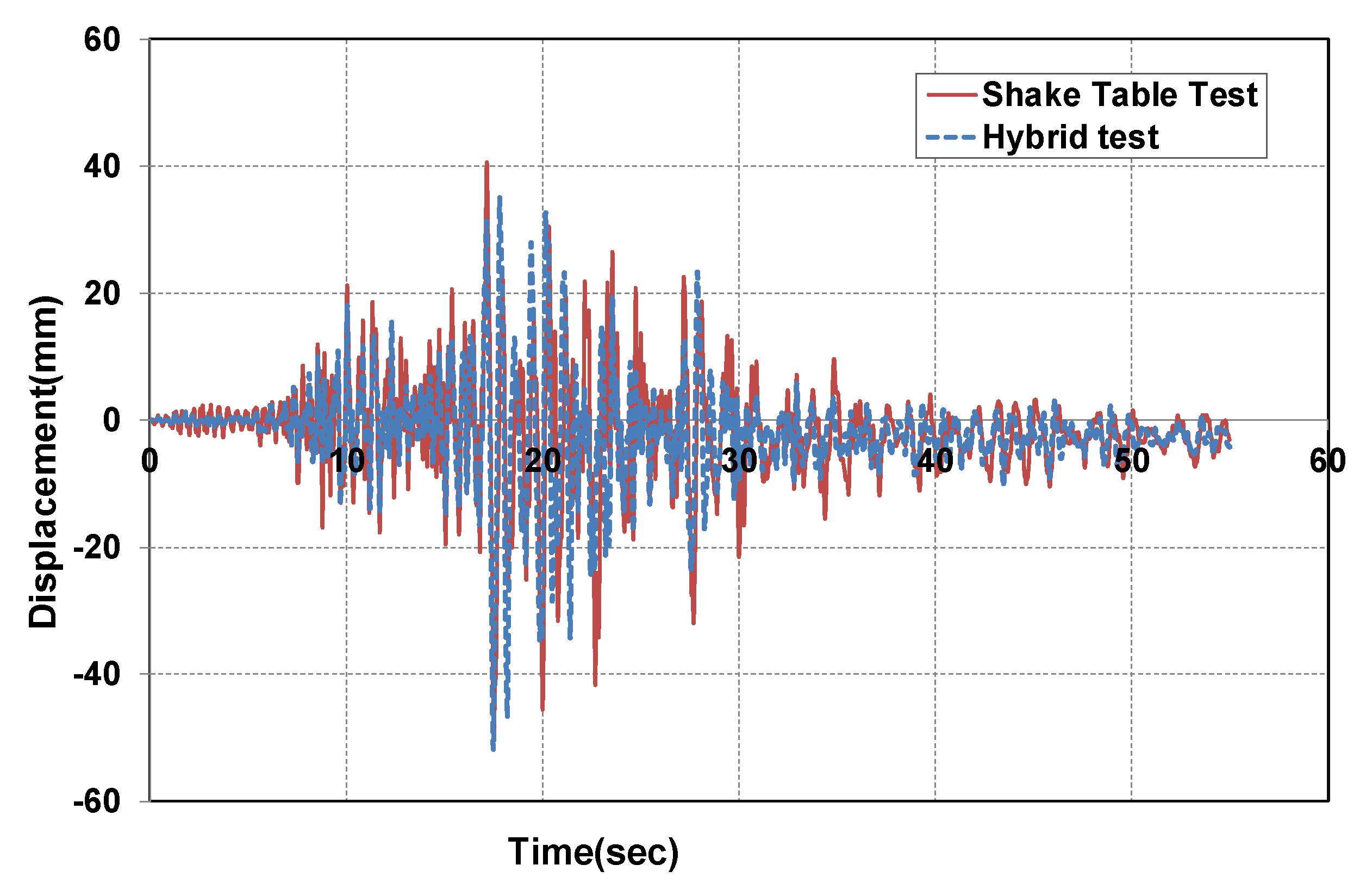
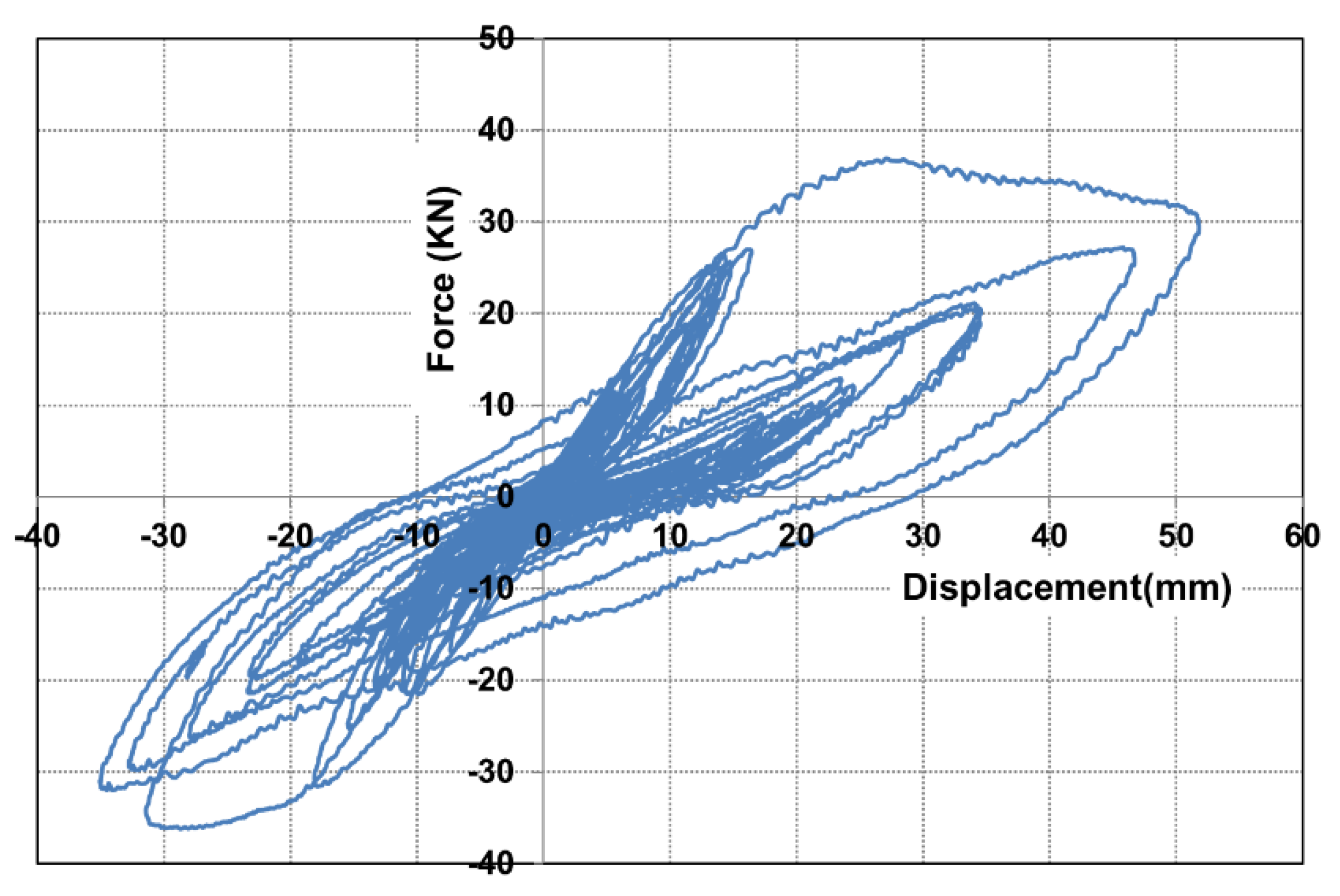
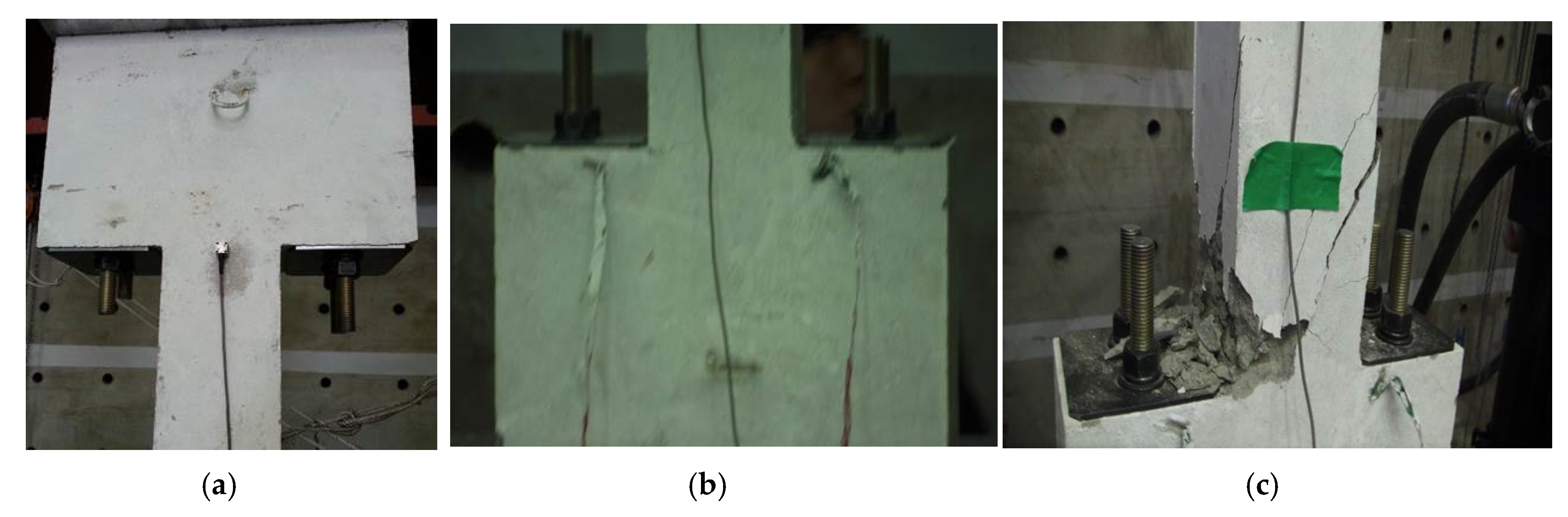
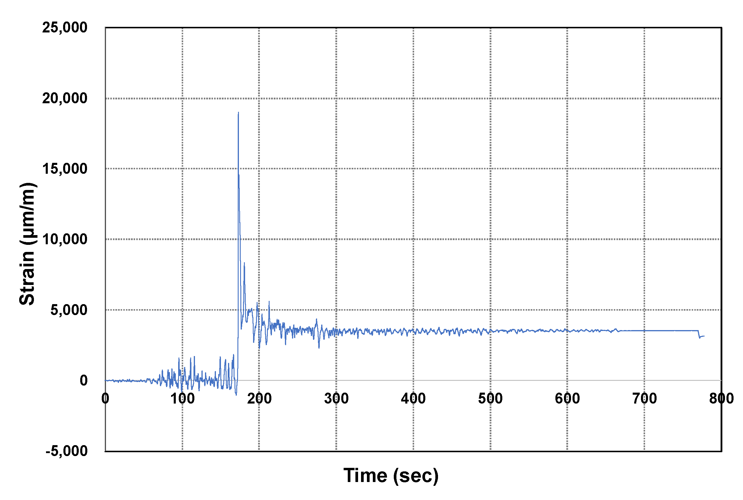
5.2. Three-DOF Structural Dynamic Test with Concrete Structure

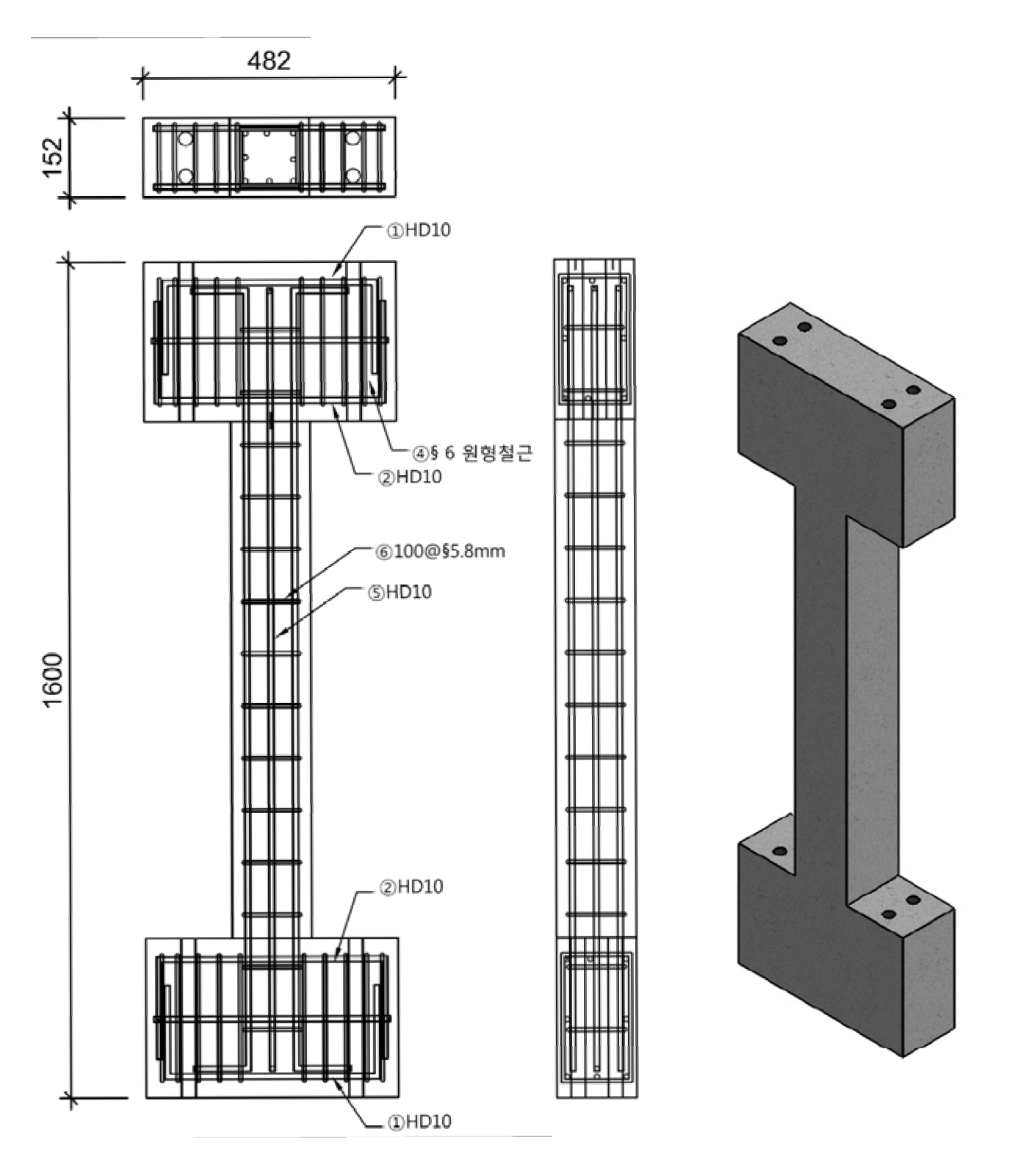
5.2.1. Test Set-Up and Input Properties

The concrete specimen used in this study was a three-story and three-span concrete frame suggested by Ghannoum [32]. In this experiment, as shown in Figure 15, the first-tier third column with less shear reinforcement was used as the physical substructure. For the numerical model, beam-column elements provided by FEAPH were used. Especially, the parts with high deformation were analyzed using zero-length elements. The compressive strength of concrete was 25 MPa and the Gluffre-Menegotto-Pinto (GMP) model was applied to the material properties of the rebar. For detailed physical properties see Ghannoum [32]. Figure 16 shows the reinforcement and final completeness of the specimen used as the physical substructure, and Figure 17 shows the three actuators mounted on the concrete specimen. Figure 18 shows the acceleration obtained from the lower part of the concrete model by performing the input seismic wave extracted from Northridge seismic wave by Ghannoum in the shaking table test.

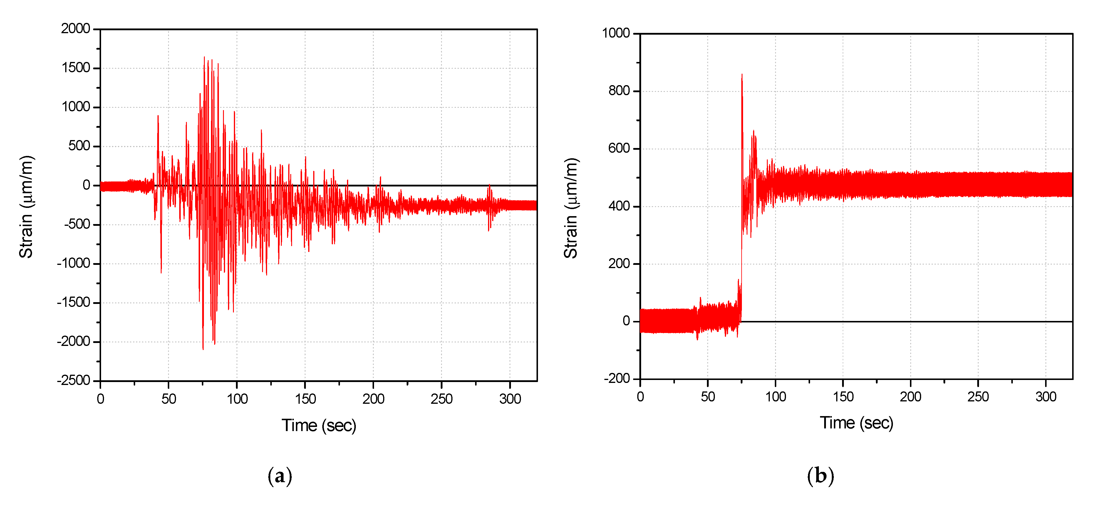
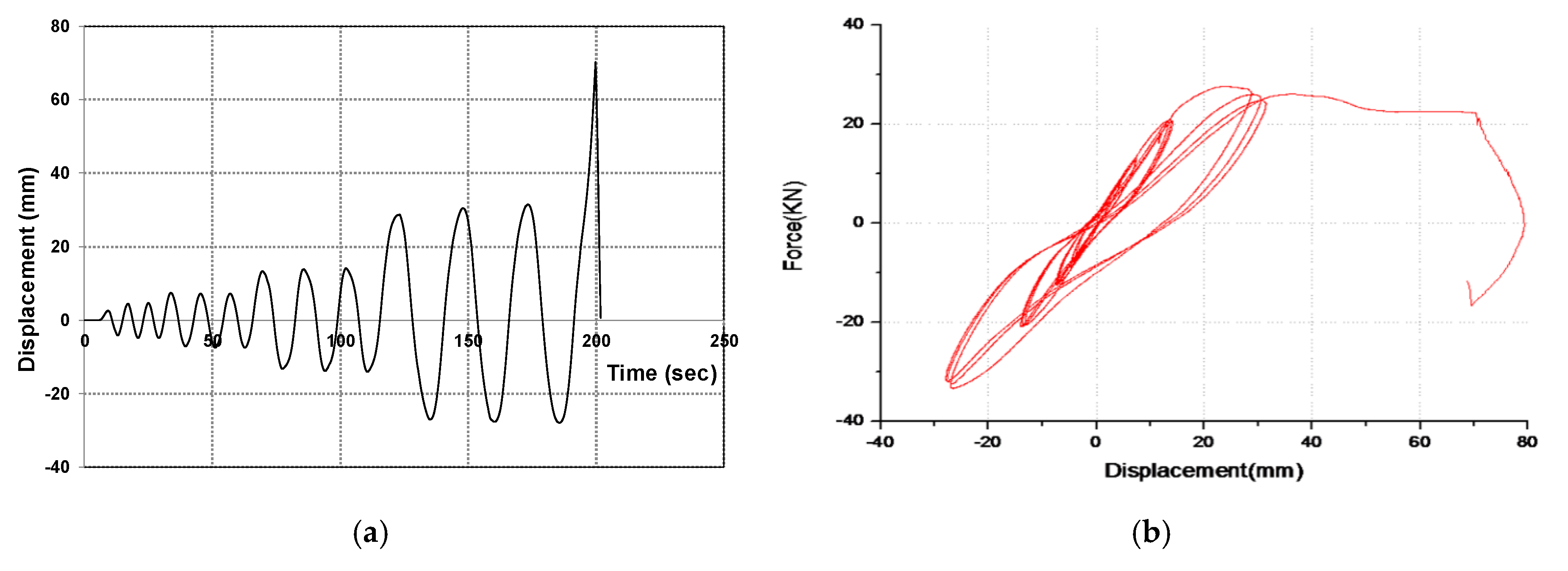
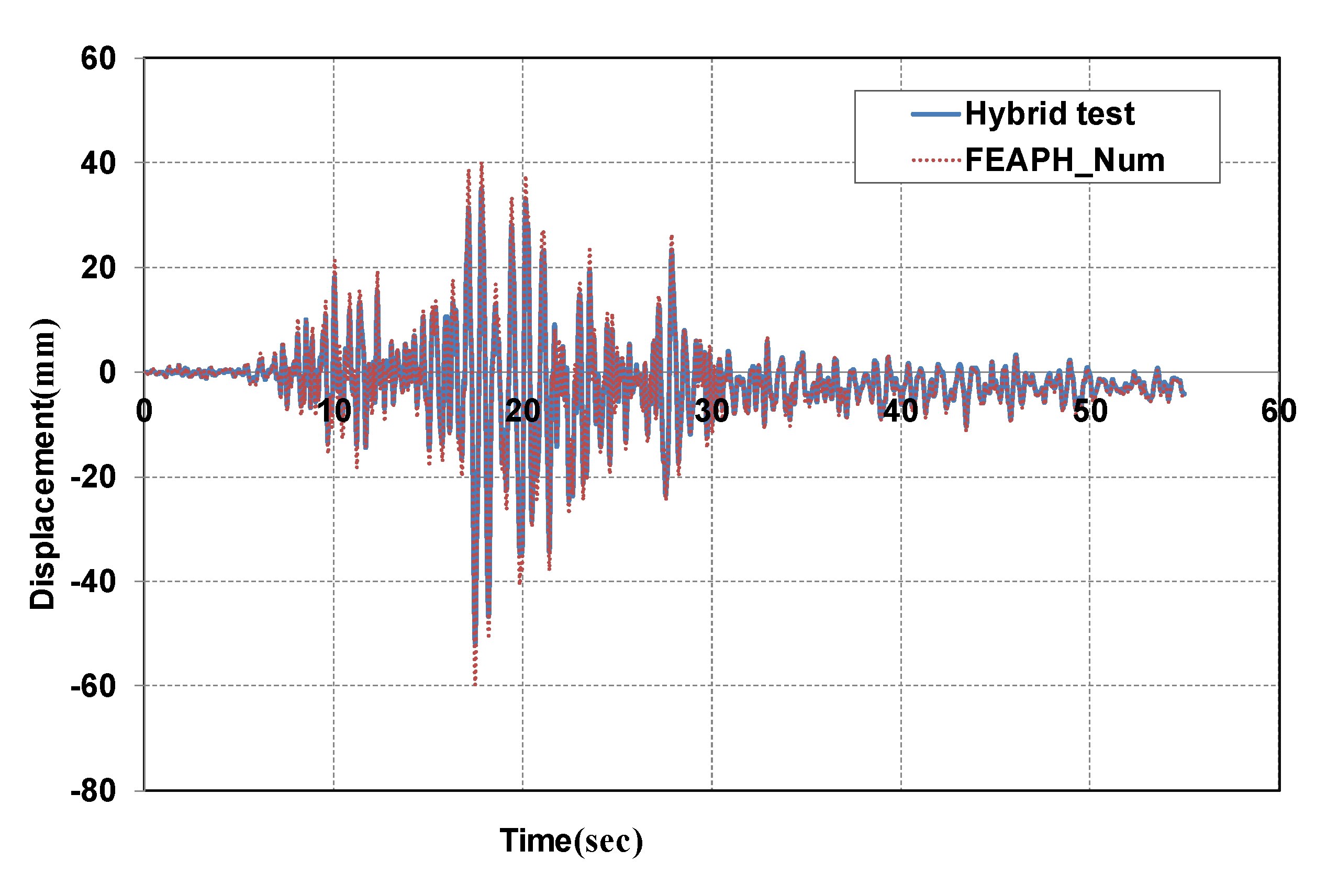
5.2.2. Non-Linear Dynamic Test with Real-Time Hybrid Control System

To ensure the response in the nonlinear dynamic test before the multiple degree of real-time hybrid test, the preliminary test was conducted with concrete specimens as shown in Figure 19. For the feasible nonlinear dynamic behavior, the wave-like displacement input was used as shown in Figure 19a. The wave acceleration was gradually increased from linear range to about 70 mm in order to show the variation between linear behavior and nonlinear one and to predict the maximum displacement and load of the concrete structure. Figure 19 graphically shows the displacement versus time history and displacement-load results and the total time was about 200 s. As a result, the absolute maximum displacement value was about 30 mm and the maximum load was 35 kN.
After verifying the feasibility through preliminary tests, a real-time hybrid test was performed for the concrete structure. Figure 20 describes the comparison of the results of FEAPH numerical analysis and the RTHT under the same condition. To analyze the reliability and applicability, Figure 21 shows the result of comparing the real-time hybrid test and shaking table experiment. Table 2 describes the comparison of maximum displacement error and root mean square (RMS) error. RMS error is derived from Equation (15) and the evaluation of the error value can be more accurate as close to zero (0) [33].
R M S   e r r o r = i j = 1 n ( d i a ( j ) d i b ( j ) ) 2 i j = 1 n ( d i a ( j ) ) 2
In Figure 20, the maximum displacement from the numerical analysis is about 60 mm. The maximum displacement by the real-time hybrid test was about 52 mm, which was reduced by about 13% as shown in Table 2. This is because the material nonlinear model of concrete and reinforcement used in the numerical analysis contains a lot of errors, which seems to be somewhat different from the actual behavior. On the other hands, the real-time hybrid test was almost in agreement with the results of the shaking table test. The peak displacement error and RMS error were good evidence in Table 2. This is because the real-time hybrid test can consider the actual material property. That is, the measured displacements and loads obtained from the feedback of the actuators can be applied to the numerical model, so that the next command displacement can be corrected.
Figure 22 also shows the relationship between the displacement and the load occurring at the top of the specimen. Over time, cracks develop in the concrete, which results in a non-linear behavior with sudden changes in displacement and a sharp decrease in strength as the load increases. This resulted in many cracks and peelings as the steel thickness in the upper and lower right corners (see Figure 23c). Figure 24 shows the strain over time measured by installing a strain gauge on the rebar in concrete. This is the result measured at the position where Figure 23c breakage occurred. Afterward 200 s in Figure 10, the reinforcing bars suddenly shifted and then about 4000 microstrains remained as residual strain. The reinforcement concrete specimens show the sudden large displacement and load. Therefore, the real-time hybrid test method used in this study can be effectively used for the economic prediction of dynamic performance of reinforced concrete structures.

6. Conclusions

In order to predict the nonlinear structural dynamic behavior, the real-time hybrid test is an effective and economical method. The purpose of this study is to verify the reliability of the simplified real-time hybrid control system and a nonlinear finite element analysis program for investigating the dynamic characteristics of structures with nonlinear materials.
This research firstly demonstrated the configuration of the simplified hybrid control systems with optimized computing environments and then the numerical algorithms adopted to FEAPH (Finite Element Analysis Program for Hybrid test) were implemented.
To verify the accuracy and stability of the performance of the real-time hybrid control system, various numerical simulations and real-time hybrid dynamic tests were conducted on steel and concrete frame structures.
For the accuracy and stability of the hybrid control system, the 3DOF linear dynamic test with steel frame was conducted. As the result, the difference between computation and linear hybrid was below 5%. This hybrid control system was proved to be stable and accurate to predict the linear dynamic behavior of the structure.
With the proven hybrid control system, finally, the reliability of nonlinear dynamic behavior was evaluated through 3DOF nonlinear dynamic tests with steel and concrete frame structures. As a result, in steel structure, the difference between numerical analysis and hybrid test was about 7% and this difference would be caused by the damping ratio, material model, and the experimental error. In concrete structure, the real-time hybrid test was almost in agreement with the results of the shaking table test simulating the actual dynamic behavior of the structure.
Therefore, the real-time hybrid control system with FEAPH performed in this study can be positively utilized as an efficient test to replace the shaking table test and can be an effective, economical method of capturing the dynamic behavior of structures.

Author Contributions

Conceptualization, O.N. and J.P.; Data curation, O.N.; Formal analysis, O.N.; Funding acquisition, J.P.; Investigation, O.N.; Methodology, O.N. and J.P.; Validation, O.N. and J.P.; Visualization, O.N.; Writing—original draft, O.N.; Writing—review & editing, J.P. All authors have read and agreed to the published version of the manuscript.

Funding

This research received no external funding.

Conflicts of Interest

The authors declare no conflict of interest.

References

  1. Kim, S.; Lee, D.; Cuong, N. Shaking table tests of a two-story unbraced steel frame. J. Korean Soc. Civ. Eng. 2005, 25, 601–609. [Google Scholar] [CrossRef]
  2. Hakuno, M.; Shidawara, M.; Hara, T. Dynamic destructive test of a cantilever beam controlled by an analog computer. Trans. Jpn. Soc. Civ. Eng. 1969, 171, 1–9. (In Japanese) [Google Scholar] [CrossRef] [Green Version]
  3. Takanashi, K.; Nakashima, M. Japanese activities on online testing. J. Eng. Mech. 1987, 113, 1014–1032. [Google Scholar] [CrossRef]
  4. Mahin, S.A.; Shing, P.S.B.; Thewalt, C.R.; Hanson, R.D. Pseudo-dynamic test method: Current status and future direction. J. Eng. Mech. 1989, 115, 2113–2128. [Google Scholar]
  5. Shing, P.B.; Nakashima, M.; Bursi, O.S. Application of pseudo-dynamic test method to structural research. Earthq. Spectra 1996, 12, 1121–1141. [Google Scholar] [CrossRef]
  6. Nakashima, M. Development, potential, and limitations of real-time online (pseudo-dynamic) testing. Phil. Trans. R. Soc. A. 2001, 359, 1851–1867. [Google Scholar] [CrossRef]
  7. Darby, A.P.; Blakeborough, A.; Williams, M.S. Real-time substructure tests using hydraulic actuator. J. Eng. Mech. 1999, 125, 1133–1139. [Google Scholar] [CrossRef]
  8. Darby, A.P.; Blakeborough, A.; Williams, M.S. Improved control algorithm for real-time substructure testing. Earthq. Eng. Struct. Dyn. 2001, 30, 431–448. [Google Scholar] [CrossRef]
  9. McKenna, F.T. Object-Oriented Finite Element Programming: Frameworks for Analysis, Algorithms, and Parallel Computing. Ph.D. Thesis, University of California, Berkeley, CA, USA, 1997. [Google Scholar]
  10. Fenves, G.L.; McKenna, F.; Scott, M.H.; Takahashi, Y. An object-oriented software environment for collaborative network simulation. In Proceedings of the 13th WCEE, Vancouver, BC, Canada, 1–6 August 2004. [Google Scholar]
  11. Schellenberg, A.; Mahin, S. Integration of hybrid simulation within the general-purpose computational framework OpenSees. In Proceedings of the 8th National Conference on Earthquake Engineering, EERI, San Francisco, CA, USA, 18–22 April 2006. [Google Scholar]
  12. Jung, R.Y.; Shing, P.B. Performance evaluation of a real-time pseudo-dynamic test system. Earthq. Eng. Struct. Dyn. 2006, 35, 789–810. [Google Scholar] [CrossRef]
  13. Bonnet, P.A. The Development of Multi-Axis Real-Time Substructure Testing. Ph.D. Thesis, University of Oxford, England, UK, 2006. [Google Scholar]
  14. Abbiati, G.; Whyte, C.A.; Dertimanis, V.K.; Stojadinovic, B. Hybrid simulation of large-scale structures at ETH Zürich: The new 8-actuator multi-axial subassemblage testing (MAST) setup. In Proceedings of the 16th World Conference on Earthquake, Santiago, Chile, 9–13 January 2017. [Google Scholar]
  15. Chen, Z.; Wang, H.; Wang, H.; Jiang, H.; Zhu, X.; Wang, K. Application of the Hybrid Simulation Method for the Full-Scale Precast Reinforced Concrete Shear Wall Structure. Appl. Sci. 2018, 8, 252. [Google Scholar] [CrossRef] [Green Version]
  16. Kang, D.H. An Optimized Computational Environment for Real-Time Hybrid Simulation. Ph.D. Thesis, University of Colorado, Boulder, CO, USA, 2010. [Google Scholar]
  17. Saouma, V.; Kang, D.H.; Haussmann, G. A computational finite element program for hybrid simulation. Earthq. Eng. Struct. Dyn. 2011, 41, 375–389. [Google Scholar] [CrossRef]
  18. Dion, C.; Bouaanani, N.; Tremblay, R.; Lamarche, C.P.; Leclerc, M. Real-Time Hybrid Testing of Seismic Protective Systems for Bridge Structures. In Proceedings of the 9th U.S. National and 10th Canadian Conference on Earthquake Engineering, Toronto, ON, Canada, 25–29 July 2010. [Google Scholar]
  19. Tsitos, A.; Bousias, S.; Dimitropoulou, E. Hybrid Testing of Bridge Structures Supported on Elastomeric Bearings. In Proceedings of the 15 WCEE, Lisabon, Portugal, 24–28 September 2012. [Google Scholar]
  20. Jiang, Z.; Kim, S.J.; Plude, S.; Christenson, R. Real-time hybrid simulation of a complex bridge model with MR dampers using the convolution integral method. Smart Mater. Struct. 2013, 22, 1–10. [Google Scholar] [CrossRef]
  21. Abbiati, G.; Bursi, O.S.; Caperan, P.; Sarno, L.D.; Molina, F.J.; Paolacci, F.; Pegon, P. Hybrid simulation of a multi-span RC viaduct with plain bars and sliding bearings. Earthquake Engng Struct. Dyn. 2015, 44, 2221–2240. [Google Scholar] [CrossRef]
  22. Vilsen, S.A.; Sauder, T.; Sorensen, A.J.; Fore, M. Method for Real-Time Hybrid Model Testing of Ocean Structures: Case Study on Horizontal Mooring Systems. Ocean. Eng. 2019, 172, 46–58. [Google Scholar] [CrossRef]
  23. Chang, Y.Y.; Yang, Y.S.; Wang, S.J.; Lin, M.L.; Weng, Y.T.; Wang, K.J.; Deng, H.Z.; Lau, D.T.; Tsai, K.C. Hybrid Testing of a Multi-Span Bridge. In Proceedings of the Advances in Experimental Structural Engineering, Nagoya, Japan, 19–21 July 2005; pp. 307–314. [Google Scholar]
  24. Bousias, S.; Sextos, A.; Kwon, O.S.; Taskari, O.; Elnashai, A.; Evangeliou, N.; Di Sarno, L. Intercontinental Hybrid Simulation for the Assessment of a Three-Span R/C Highway Overpass. J. Earthq. Eng. 2019, 23, 1194–1215. [Google Scholar] [CrossRef] [Green Version]
  25. Cho, S. Improvement of Hybrid Test System and Its Application to a Small Experimental Model. Ph.D. Thesis, MyongJi University, Seoul, South Korea, 2011. [Google Scholar]
  26. Lee, J. Evaluation of Applicability and Reliability for Hybrid Testing. Ph.D. Thesis, Inha University, Incheon, South Korea, 2012. [Google Scholar]
  27. Kim, S.; Na, O.; Kim, S.; Kang, D.H. Single degree of freedom hybrid dynamic test with steel frame structure. J. Korean Soc. Railw. 2012, 5, 413–421. [Google Scholar] [CrossRef]
  28. Wei, Z. Fast Hybrid Test System for Substructure Evaluation. Ph.D. Thesis, University of Colorado, Boulder, CO, USA, 2005. [Google Scholar]
  29. Chen, C.; Ricles, J.M. Analysis of implicit HHT-α integration algorithm for real-time hybrid simulation. Earthq. Eng. Struct. Dyn. 2012, 41, 1021–1041. [Google Scholar] [CrossRef]
  30. Chen, C.; Ricles, J.M.; Karavasilis, T.L.; Chae, Y.; Sause, R. Evaluation of a real-time hybrid simulation system for performance evaluation of structures with rate-dependent devices subjected to seismic loading. Eng. Struct. 2012, 35, 71–82. [Google Scholar] [CrossRef]
  31. American Institute of Steel Construction Inc. Seismic Provisions for Structural Steel Buildings; AISC: Chicago, IL, USA, 2002; pp. 383–403. [Google Scholar]
  32. Ghannoum, W.M. Experimental and Analytical Dynamic Collapse Study of a Reinforced Concrete Frame with Light Transverse Reinforcement. Ph.D. Thesis, University of California, Berkeley, CA, USA, 2007. [Google Scholar]
  33. Karavasilis, T.L.; Ricles, J.M.; Sause, R.; Chen, C. Experimental Evaluation of the Seismic Performance of Steel Buildings with Passive Dampers Using Real-Time Hybrid Simulation. In Role of Seismic Testing Facilities in Performance-Based Earthquake Engineering. Geotechnical, Geological, and Earthquake Engineering; Fardis, M., Rakicevic, Z., Eds.; Springer: Dordrecht, The Netherlands, 2012; Volume 22, pp. 323–343. [Google Scholar]
Figure 1. System Configuration for real-time hybrid test (RTHT).
Applsci 10 04037 g001
Figure 2. Schematic Diagram and organization of Finite Element Analysis Program for Hybrid test (FEAPH) (a) Simplified RTHT system with FEAPH window; (b) Internal organization of FEAPH program.
Applsci 10 04037 g002
Figure 3. Numerical Algorithm used in FEAPH.
Applsci 10 04037 g003
Figure 4. Quadratic Interpolation.
Applsci 10 04037 g004
Figure 5. 1-bay, 2-story steel structure model.
Applsci 10 04037 g005
Figure 6. Test set-up for steel frame and actuators.
Applsci 10 04037 g006
Figure 7. El Centro ground acceleration.
Applsci 10 04037 g007
Figure 8. Accelerometer and strain gauge.
Applsci 10 04037 g008
Figure 9. Comparison of numerical and hybrid test result.
Applsci 10 04037 g009
Figure 10. Force vs. displacement at 1st floor.
Applsci 10 04037 g010
Figure 11. Comparison of numerical and hybrid test results; (a) 1st floor displacement (b) 2nd floor displacement.
Applsci 10 04037 g011
Figure 12. Force vs. displacement at 1st floor.
Applsci 10 04037 g012
Figure 13. Acceleration at 1st floor.
Applsci 10 04037 g013
Figure 14. Response of strain gauges; (a) Flange (strain gauge #1) (b) web (strain gauge #2).
Applsci 10 04037 g014
Figure 15. Dimension of reinforced concrete frame.
Applsci 10 04037 g015
Figure 16. Rebar arrangement detail of test specimen at 1st flr.-3rd col.
Applsci 10 04037 g016
Figure 17. Installation of the concrete specimen and actuators.
Applsci 10 04037 g017
Figure 18. Northridge ground acceleration.
Applsci 10 04037 g018
Figure 19. Verification of RTHT for Non-linear Model; (a) Wave displacement input (b) Force-displacement.
Applsci 10 04037 g019
Figure 20. Results of numerical analysis and real-time hybrid test.
Applsci 10 04037 g020
Figure 21. Result of shaking table and real-time hybrid test.
Applsci 10 04037 g021
Figure 22. Force and displacement at the top of the specimen.
Applsci 10 04037 g022
Figure 23. 3-DOF hybrid test for concrete frame; (a) Accelerator (b) Strain gauges (c) Fracture shape.
Applsci 10 04037 g023
Figure 24. Strain on top of the concrete specimen.
Applsci 10 04037 g024
Table 1. Section properties of the specimen.
H (mm)B (mm)tf (mm)tw (mm)r (mm)Ag (mm2)Ix (106mm4)Iy (106mm4)
12512596.51030318.472.92
Table 2. Comparison of peak displacement value error and root mean square (RMS) error.
FEAPH_Num (A)Shake Table Test (A)
Real-Time Hybrid Test (RTHT) (B)Real-Time Hybrid Test (RTHT) (B)
Peak displacement error (%) 113.32.3
RMS (Root Mean Square) error0.7990.203
1 Peak displacement error = (A − B)/B × 100.

