2. Switched-Mode Power Supply
The GAD plasma reactor is a non-linear energy receiver, hence the special requirements for switched-mode power supply (SMPS), which is used to supply non-thermal μGAD discharges. First, the power supply must generate a high voltage, adapted primarily to the type of process gas and the electrodes’ distance in the ignition zone, in order for the discharge in the process gas to ignite cyclically without additional ignition electrodes, initial ionization, and radiation. Secondly, it is beneficial for the power supply from the receiver’s point of view to have the characteristics of a regulated power source. Therefore, the SMPS source should quickly and efficiently limit the discharge current, which subsequently maintains a stable glow discharge.
These SMPS properties have been achieved by combining many standard and custom energy conversion techniques in a pulse inverter. The use of a push–pull topology is common for converters increasing DC voltage by several dozen volts. Here, the push–pull inverter was used to take advantage of the parasitic phenomenon of commutation overvoltage, and thus improve the ignition parameters in μGAD. The push–pull topology is characterized by a complex primary winding with a tap in its half (two-section winding), to which the inverter’s asymmetry is very sensitive. Despite the significant multiplication of voltages, making the primary winding is not complicated; it is much more difficult to design and make a high voltage secondary coil. Push–pull systems show good properties at high frequencies—comparable to full-bridge ones, which limits Miller’s effect. However, they are rarely used to power digital electronics, because the switching surges arising in them require limitation and protection of the output stage, especially for sensitive microprocessor technology.
The use of full-bridge push–pull topology is non-standard, due to its properties. Assuming identical parameters of the supply voltage Uin, output voltage Uout, rated power Pn, operating frequency f, and input current In, comparing the popular “H” full-bridge topology (push–pull), it should be assumed that, in a bridge converter, there are 4 fully controlled connectors and therefore inverter supply voltage Uin, inverter output voltage Us, voltage on the primary winding Up, and voltage on the Ut controllable switches are equal to the supply voltage Uin, while the current of the switch It is equal to the input current In, and the transformer ratio equals N.
In half-bridge push–pull topology, the output voltage of the inverter Us is equal to the supply voltage Uin. The voltage at the Ut controlled switch is doubled in the pulsing half-period, which is the result of the simultaneous sum of DC side voltages and the blocked primary winding voltage, which in turn is considered unfavorable in push–pull topology. The voltage on the full primary winding Up is equal to doubled supply voltage 2Uin, while the current of the controlled switch It is approximately equal to the input current In, and the transformer ratio is 2N.
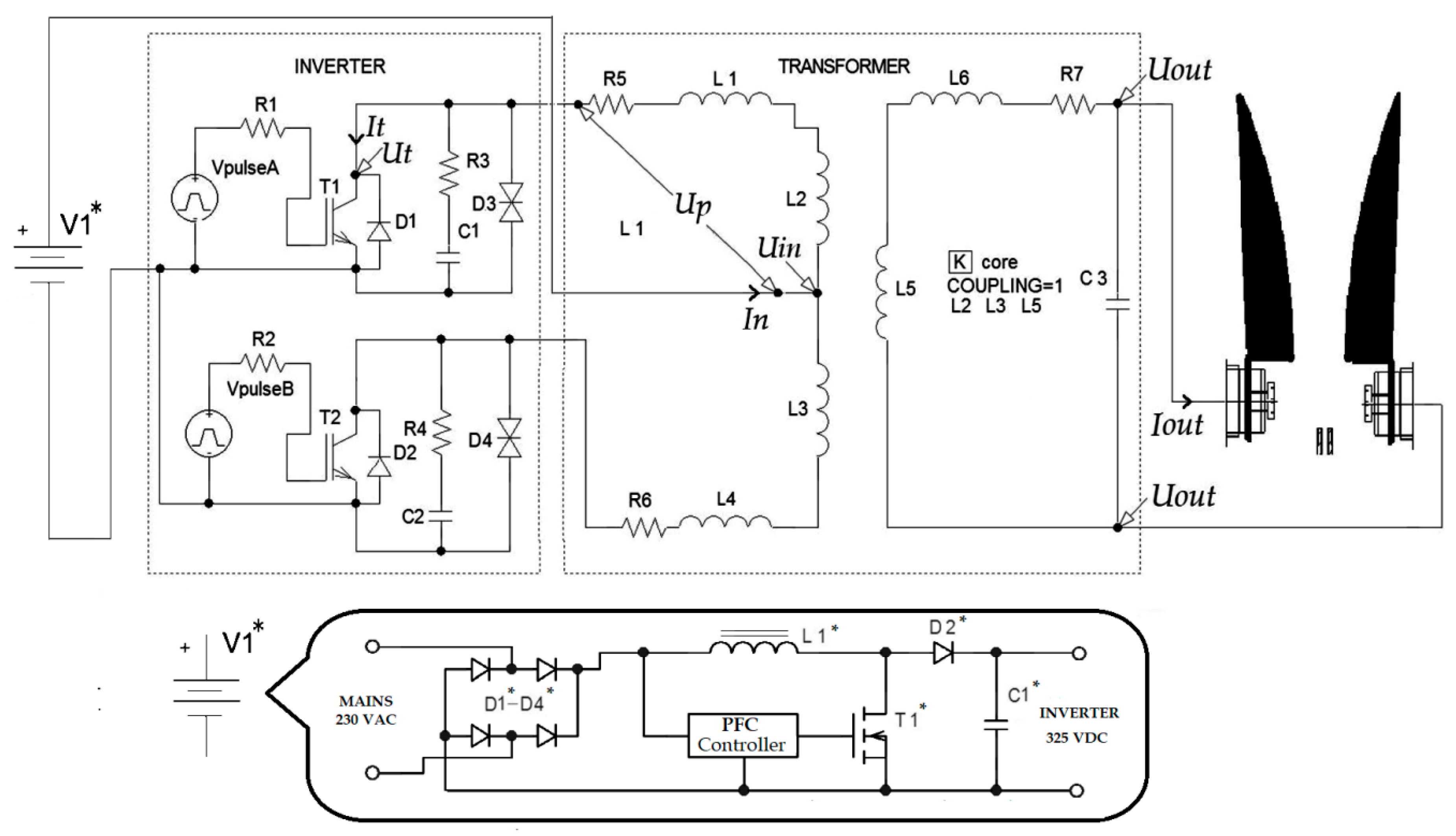
To describe the use of parasitic phenomena during energy conversion, a simplified diagram of this system is outlined in
Figure 1. The input side of the power supply is standard for SMPS devices and has an input rectifier and filtering capacitors. There is also a power factor correction (PFC) compensator and a system for pre-charging capacitors. In this way, DC voltage is prepared to supply the push–pull topology converter. These are solutions that are treated as a standard in pulse technology and do not differ in this non-thermal plasma NTP power supply. Therefore, no details are referred to in this article.
As it can be seen in
Figure 1, the positive pole of the filtered DC voltage is applied to the center tap in the primary coil. The 0 potential is connected alternately to the beginning and the end of the winding, according to the frequency and a pulse period. Executive valves are insulated gate bipolar transistor (IGBT). Switches designated as T1 and T2. Coils L2, L3, and L5 remain magnetically coupled in the substitute diagram. Coils L1, L4, and L6 represent leakage inductances.
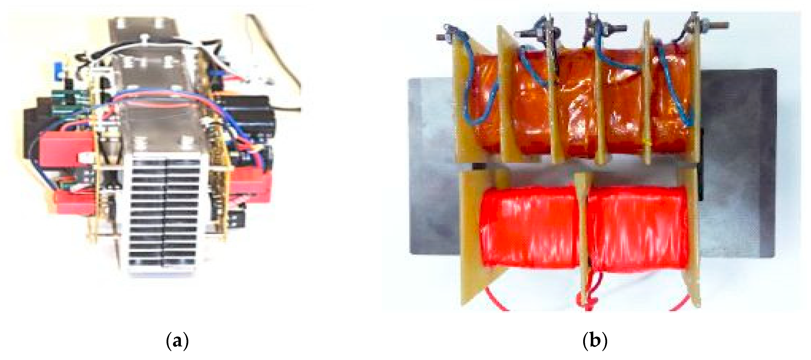
The switching power supply is shown in
Figure 2.
During the pulse repetition, the fast-changing current is led through the rising edge to the magnetically coupled transformer coils, where the energy is transported to the secondary side via a magnetic flux. The fast current changes strongly depend on the leakage inductances. This is crucial due to the commutation overvoltages arising during the changes in current. Basically, they are used to generate high-voltage pulses (HVP) to support ignition of the plasma reactor. HVP can be used when the transformer’s core was chosen in such a way as not to be a part of a low-pass filter for HVP. The voltage value of the switching overvoltage must be limited, due to the exposure of the switching elements in the primary current control system. That is why a special overvoltage control system was used. These are resistive-capacitive RC snubbers composed of elements R3, R4, and C1, C2. RC parameters require precise empirical selection. In addition, TRANSIL diodes (D3, D4) were introduced so that their speed and non-linearity would protect IGBTs. The system also has a secondary dissipation reactance and a C7 capacitor representing the parasitic capacity of the secondary side [
3,
8,
9]. To see the non-standardity of the solution, it should be noted that typical push–pull power supplies attention is not being paid to obtain significant leakage inductances. The windings are placed on the U–U core on separate columns here, to gain the appropriate characteristics and safety. This fact highly increases the scatter reactance. Under normal circumstances, they are limited as well as the resulting surges.
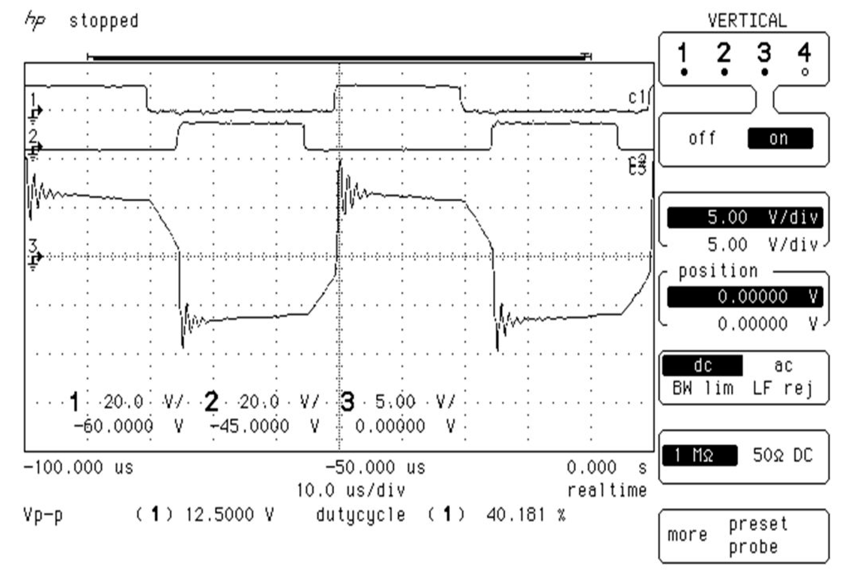
To be able to explain parasitic phenomena, the following simplifications can be made: It is necessary to isolate the resonance circuit for suppressed resonance, for example within the transistor T1. This circuit has C1 capacity and should be considered as the main one. In addition, there are parasitic capacitances (output of the T1 transistor, parasitic capacitances of the parallel diode, and transil diode). There is also parasitic capacitance within the primary coil. Inductance should be also indicated: main (L2), magnetically coupled in the transformer, and parasitic, marked as L1. Energy can be accumulated in both inductance as well as capacitance, and it is supplied when the transistor is turned on. Due to the fact that the principle of conservation of energy is obeyed, closing the transistor causes the energy to be redistributed repeatedly between inductance and capacitance. It is natural that, in this circuit, there is a coupled L2 coil that causes the transfer of surges to the secondary side. There are also attenuations and these are mainly resistances, including the deliberately introduced RC snubber resistance. Overvoltages were limited by the modulation of a current derivative and cut off with transil diodes. To give an idea of the quantitative parameters of the surge energy, there can be recalled the physical RC parameters of the selected snubber and the resistance of 22 ohms, and the capacity of several nanofarads. The overvoltage parameters are clearly visible in
Figure 3.
4. Discussion
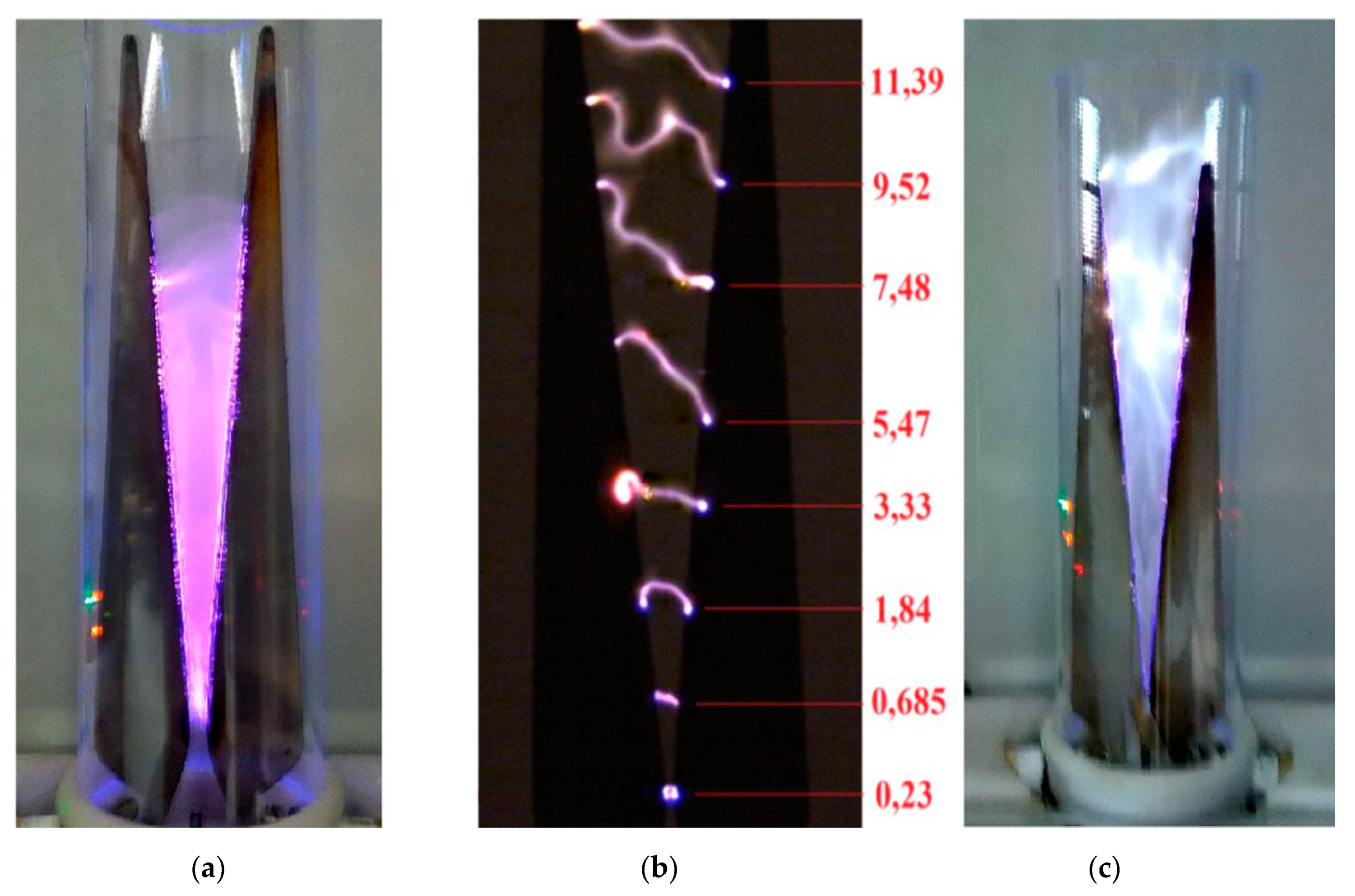
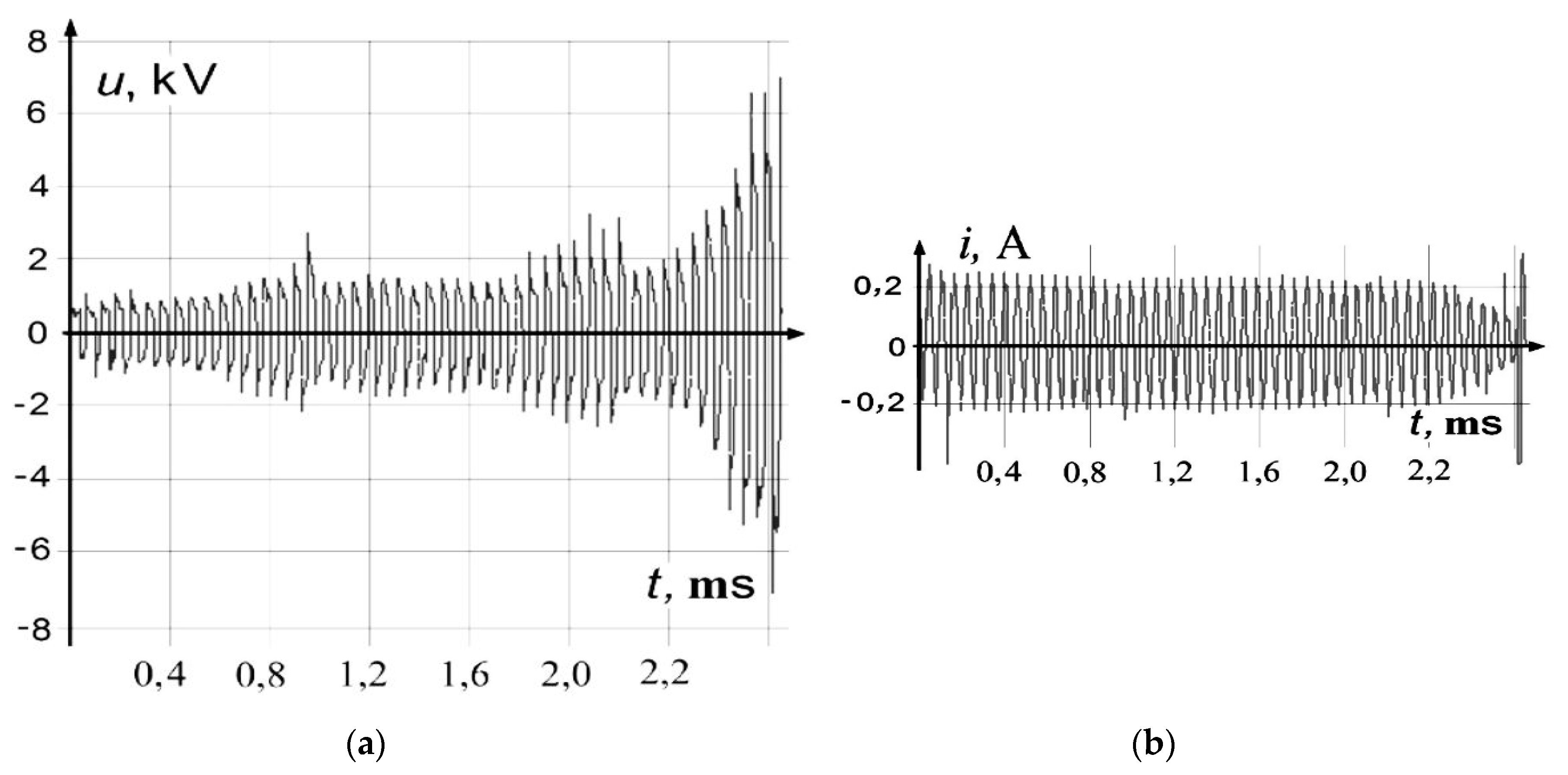
Measurements and oscilloscopic studies show that waveforms in the plasma cycle are characterized by two periodicities. One of them results from the pulse frequency in SMPS and another one from the plasma cycle itself. About 50 pulse periods and a plasma cycle with a length of about 2.5 ms were observed on the waveforms. It was noted that in the plasma cycle, after ignition, the voltage reached a value of up to 0.5 kV. Then, the arc column moving up the electrodes lengthens and bends, reducing its conductance, and the voltage increases gradually, reaching 7 kV at the tip of the electrodes. The reactor current changes the opposite way. After ignition, SMPS effectively limits the peak values at the level of 0.22 A, and this value remained in the plasma cycle until the discharge conductance caused a current drop.
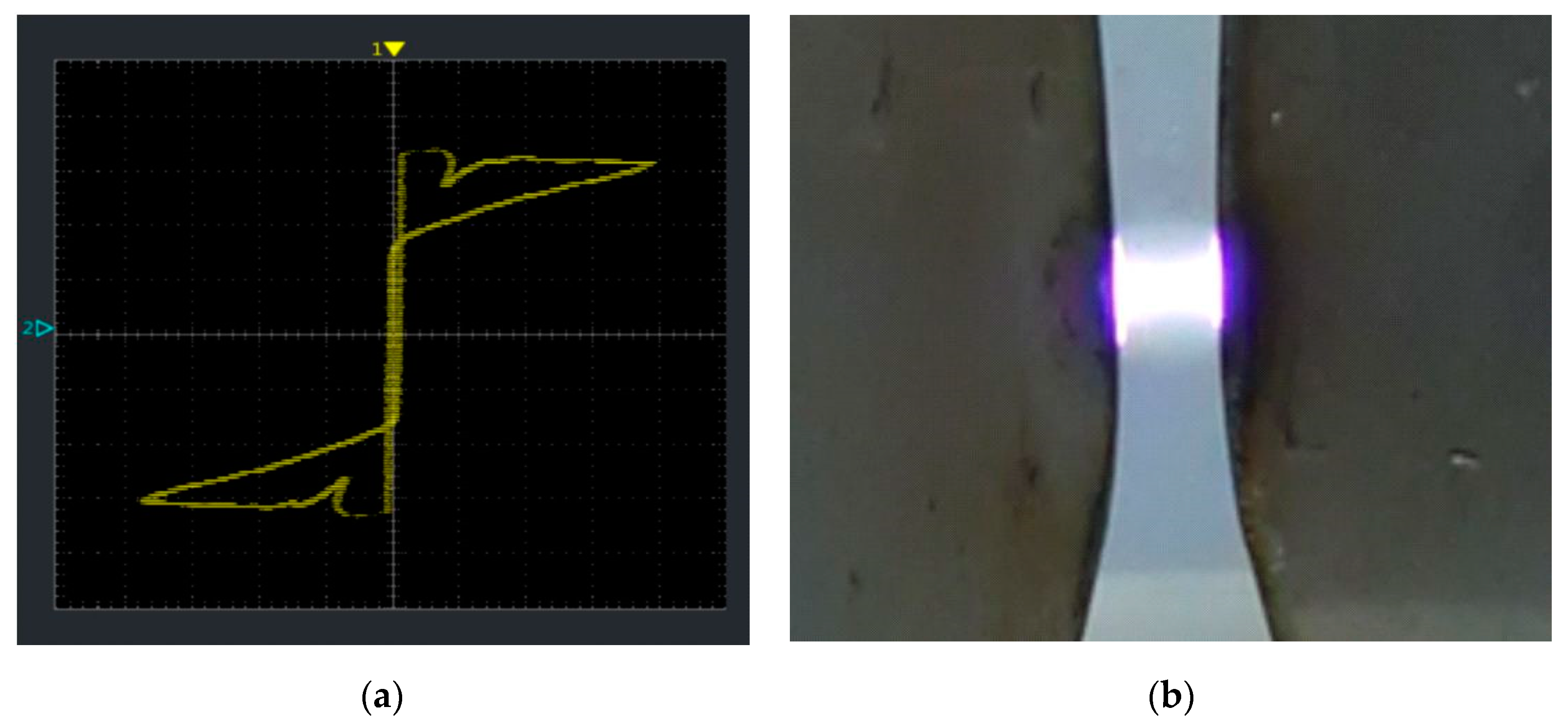
The discharge at the pulse–power source at 20 kHz (
Figure 5) from the beginning presents different features from the discharge at 50 Hz. If the process gas stream is not fed through the nozzle, the discharge does not develop and moves up the electrodes, remaining in the ignition zone, and its voltage reaches hundreds of volts, due to the non-linearity of the receiver, which is the μGAD reactor’s domain.
It is crucial how the traveling discharge changes its electrical parameters. With pulsed power supply and process gas distribution, observing the plasma reactor, one gets the impression that the discharge penetrates the inter-electrode space very closely. In noble gases, discharges are even more homogeneous. A photograph taken with an exposure time of 0.01 s does not allow observing the arc sliding over the knife electrodes. Only a fast camera test demonstrates the actual sliding movement of the discharge column along the knife electrodes.
5. Conclusions
On the basis of the research, it can be concluded that the non-standard push–pull topology may be successfully implemented in the power supply to conduct GADs. In addition, it should be said that the use of parasitic parameters in the form of leakage inductance allows an effective generation of ignition overvoltages. This, in turn, allows a 60% increase in voltage for GAD ignition.
It is also necessary to indicate some restrictions related to the selected topology of the power supply. If commutation overvoltages are used to improve ignition, use IGBTs with high maximum collector-emitter voltage. In this case, UCE = 1.2 kV keys were used. This is a high voltage, especially when compared to the full bridge topology, where it could be almost twice lower.
The main pulse frequency band should be defined before the design stage. For the power supply described, it would not be possible to lower the frequency to 9 kHz, in the full pulse-width modulation (PWM) control range, because the core material and the winding do not allow it. The system has similar limitations at frequencies above 26 kHz. Changing the primary winding requires precise tuning of RC surge bands so that they only eliminate overvoltages that are dangerous to IGBT keys and at the same time allow the formation of ignition overvoltages. The use of microprocessor controllers, sensitive to radiated interference and conducted from the micro-gliding arc plasma reactor, also causes many difficulties [
10]. These difficulties determined the use in the prototype of the power supply driver based on the analog, integrated PWM pulse width modulator.
The experience described in the article shows that appropriate modifications of push–pull topology, known for years, allow for the implementation of this atypical solution. Moreover, the main disadvantages of topology are used here as advantages. The power supply shows good characteristics and there is no need to use any additional ignition sources. This is very important especially in conditions of air as a plasma gas.
The designed and constructed power supply has the desired utility features required from the power electronic source of the plasma reactor. It also has numerous features that are its advantage over devices in which energy is transformed using a transformer with a network frequency, such as: good control parameters, power to volume ratio of the power supply, and high susceptibility to modifications.

