Article

Mixed Reality Simulation of High-Endurance Unmanned Aerial Vehicle with Dual-Head Electromagnetic Propulsion Devices for Earth and Other Planetary Explorations

1
Department of Aerospace Engineering, Sejong University, Seoul 05006, Korea
2
Indian Space Research Organisation, VSSC, Trivandrum 695022, India
3
Kumaraguru College of Technology, Coimbatore 641049, India
*
Author to whom correspondence should be addressed.
Appl. Sci. 2020, 10(11), 3736; https://doi.org/10.3390/app10113736
Submission received: 22 April 2020 / Revised: 22 May 2020 / Accepted: 23 May 2020 / Published: 28 May 2020
(This article belongs to the Special Issue Multi-Robot Systems: Challenges, Trends and Applications)

Abstract

:
One of the major limitations of existing unmanned aerial vehicles is limited flight endurance. In this study, we designed an innovative uninterrupted electromagnetic propulsion device for high-endurance missions of a quadcopter drone for the lucrative exploration of earth and other planets with atmospheres. As an airborne platform, this device could achieve scientific objectives better than state-of-the-art revolving spacecraft and walking robots, without any terrain limitation. We developed a mixed reality simulation based on a quadcopter drone and an X-Plane flight simulator. A computer with the X-Plane flight simulator represented the virtual part, and a real quadcopter operating within an airfield represented the real part. In the first phase of our study, we developed a connection interface between the X-Plane flight simulator and the quadcopter ground control station in MATLAB. The experimental results generated from the Earth’s atmosphere show that the flight data from the real and the virtual quadcopters are precise and very close to the prescribed target. The proof-of-concept of the mixed reality simulation of the quadcopter at the Earth atmosphere was verified and validated through several experimental flights of the F450 spider quadcopter with a Pixhawk flight controller with the restricted endurance at the airfield location of Hangang Drone Park in Seoul, South Korea. We concluded that the new generation drones integrated with lightweight electromagnetic propulsion devices are a viable option for achieving unrestricted flight endurance with improved payload capability for Earth and other planetary explorations with the aid of mixed reality simulation to meet the mission flight path demands. This study provides insight into mixed reality simulation aiming for Mars explorations and high-endurance missions in the Earth’s atmosphere with credibility using quadcopter drones regulated by dual-head electromagnetic propulsion devices.

1. Introduction

Multicopter rotorcraft unmanned aerial vehicles (UAVs) are less susceptible to turbulence as compared with similar-sized fixed wing aircraft. Among the rotorcraft, the quadcopter is the most commonly used UAV, because of its mechanical simplicity and performance [1,2,3]. Of late, the applications of quadcopter UAVs, i.e., drones are increasing dramatically due to less risk and more benefits to the operators and users in the Earth’s atmosphere. A literature review revealed that the application of drones with improved payload capability for high-endurance planetary exploration has been emerging in aerospace industries worldwide owing to the fact that a drone can map a larger planet area than a rover at a resolution far better than the existing satellites or orbiters [4,5]. It is well known that airborne platforms cover much larger distances in a single mission than a rover and can transmit high-resolution images of very rocky or steep terrain better than state-of-the-art orbiting spacecraft. Orbiters extend the facility to map large areas for a longer period of time with restricted resolution. Landers can handle the planet’s surface and atmospheric sampling but are limited to the close vicinity of the landing site. The mobility of the airborne platform is a major concern. To overcome these restrictions of orbiters and landers, we have proposed MR simulation of a high-endurance quadcopter UAV with dual-head electromagnetic propulsion (EMP) devices to maneuver to interesting sites lucratively for a longer duration through the prescribed trajectory.
A literature review revealed that there are eight listed planets and more than 160 moons known to us in the solar system. Among the planets, it has been reported that Venus, Earth, Mars, Jupiter, Saturn, Uranus, and Neptune have noteworthy atmospheres. The largest moon of Saturn, namely Titan, has been identified to have a dense atmosphere for facilitating the mobility of the airborne platforms. Over the decades, Mars has been one of the fascinating planets for scientific exploration. Flying a drone in the environment of Mars presents a major challenge, mainly because of the atmospheric characteristics of Mars. It has been reported that the density of the atmosphere of Mars is extremely low in the order of 1/70 as compared with that on Earth’s surface [6], which demands the high-speed rotor to generate sufficient lift at a low Reynolds number. The speed of sound on Mars is approximately 20% less as compared with that on Earth [6], which creates the high Mach number flows. At this atmospheric condition, designing an airborne platform for planet exploration is a challenging task. In this paper, we proposed a viable option of a new generation quadcopter UAV integrated with lightweight feedback-controlled dual-head EMP devices which achieves the variable-speed spinning rotors to obtain a desirable lift with an efficient guidance, navigation, and control system, in accordance with local atmospheric properties, for high-endurance Earth and other planetary explorations with the aid of MR simulation to meet the flight path demands of the mission.
Although many studies have been carried out on the design and development of multicopter rotorcraft from a different perspective, a limited number of studies have been carried out on MR simulation based on a quadcopter UAV and an X-Plane flight simulator [7,8,9]. In quadcopters, two motors rotate in a clockwise (CW) direction, and the remaining two motors rotate in a counterclockwise (CCW) direction, which produce zero angular momentum. In order to control the yaw, where the copter turns left and right, either the CW or CCW propellers are required to speed up or slow down to cause angular momentum to turn the copter. Quadcopters are currently used in agricultural, scientific, and commercial fields, including the military. The quadcopter works according to the speed of each rotor. Flight controller hardware is the head of any UAV, including the quadcopter. Today, the Pixhawk controller is widely used for UAV applications due to its low cost and better performance [7,8,9] and it comes with autopilot open source software and firmware.
The necessity for UAV simulations is increasing largely because there is a great deal of research taking place on UAV exploration [9,10,11]. A literature review revealed that many undesirable accidents have occurred during UAV operations due to the lack of professional pilot training [12,13,14]. Therefore, it is necessary, rather desirable, and perhaps inevitable, to develop a training device, such as the UAV simulator for new UAV users, and also for further research and development. UAV simulations have shown many benefits, including better understanding of a system and experimental flight tests before a real UAV fight. In the industry, a considerable number of flight simulation softwares are available, including X-Plane [15,16,17], FlightGear [18], Gazebo [9], and MAV3DSim [19]. The three main types of existing simulations are virtual reality (VR) simulation [20], augmented reality (AR) simulation [21], and mixed reality (MR) simulation [22]. The virtual reality simulation is a fully immersive type of simulation; it is used in computer technology to create a simulated environment. The augmented reality simulation is overlaid digital information in the real world. The mixed reality simulation is a combination of the virtual part, together with the real part, and it interacts in real time. Various research methods have been conducted on these three simulations, including the UAV field. Gongjin Lan et al. (2016) [23] developed UAV-based virtual reality systems and Shubo Wang et al. (2017) [24] constructed a virtual reality platform for UAV deep learning. Yuan Wang et al. and Li Yi-bo et al. introduced UAV with augmented reality technologies [25,26]. In MR simulation, Martin Selecký et al. [27] proposed a design for a communication architecture in unmanned systems. Fernando López Peña et al. (2017) [28] discussed an initial phase of the MR simulator for autonomous UAVs. Saimouli Katragadda et al. (2019) [29] developed a stereoscopic MR for UAV search and rescue.
Nowadays, UAVs are used for long-time missions for strategic defense, agricultural, surveillance, and rescue operations during a natural calamity. Additional surveillance applications include pipeline security, livestock monitoring, wildfire mapping, home security, road patrol, transportation, photography, and other entertainments. The main limitation of the long-time missions is the limited flight endurance due to the visibility problem of the UAV. It is well known that most UAVs have a live camera tracking system and global positioning system (GPS), but a user cannot see the overall view of an UAV during the use of these systems.
Although a large volume of simulation studies on UAVs are available in the open literature, there are no studies that address the overall view and performance of MR simulation of UAVs [27,28,29], which we have addressed, herein, along with the preliminary design of a quadcopter UAV governed by dual-head EMP devices for high endurance planetary explorations. More specifically, in this paper, we introduce a new MR simulation based on a quadcopter UAV and an X-Plane flight simulator (version 10.51). Herein, we present an overall view of the real-time performance of an UAV, which enables us to see the live performance of a real UAV quadcopter on a simulation platform. Using this MR simulation technique, we can solve the problem of limited flight endurance due to visibility problems during a long-time mission of any quadcopter.

2. Methodology

In this MR simulation, a computer with X-Plane software represented the simulation platform, and a real quadcopter within an airfield represented the real platform. In this paper, the interaction between the real and the virtual quadcopters in real time is called MR simulation. The data flow between the real and the virtual quadcopters are shown in Figure 1. More precisely, we developed a connection interface between the X-Plane flight simulator and the quadcopter ground control station (GCS) using the transmission control protocol/internet protocol (TCP/IP) [30] and the user datagram protocol (UDP) [31] in MATLAB. Both are the suite of communication protocols used for data transferring. For the simulation of the performance of the real quadcopter on the X-Plane platform, we needed the position (latitude, longitude, and altitude) and attitude (pitch, roll, and heading) data from the real quadcopter. The GCS receives the real-time flight data of the real quadcopter through a radio telemetry device. In our case, the developed connection interface needed two ways of communication; one to receive the real-time data from the GCS and the second to send the real-time position and attitude data from the received flight data to X-Plane. Therefore, here, we used, TCP/IP communication between the GCS and developed interface, and UDP communication between the developed interface and X-Plane. By using the developed connection interface, the GCS sends the real-time position and attitude data to X-Plane, and the virtual quadcopter in X-Plane follows the real quadcopter. Consequently, here, the virtual quadcopter interacted with the real quadcopter in real time (i.e., MR simulation).

3. Design of Quadcopter and Simulation Environment Setup

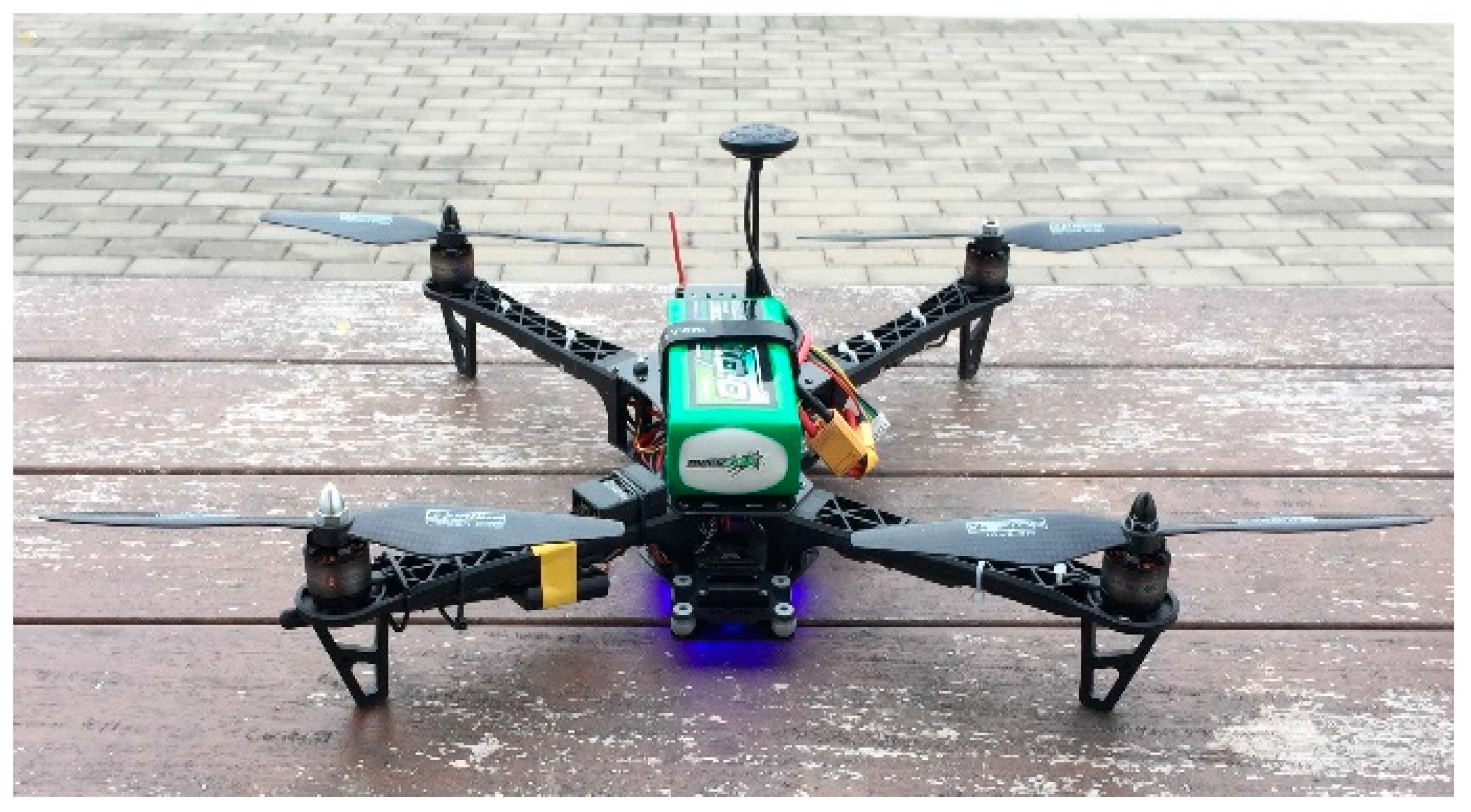
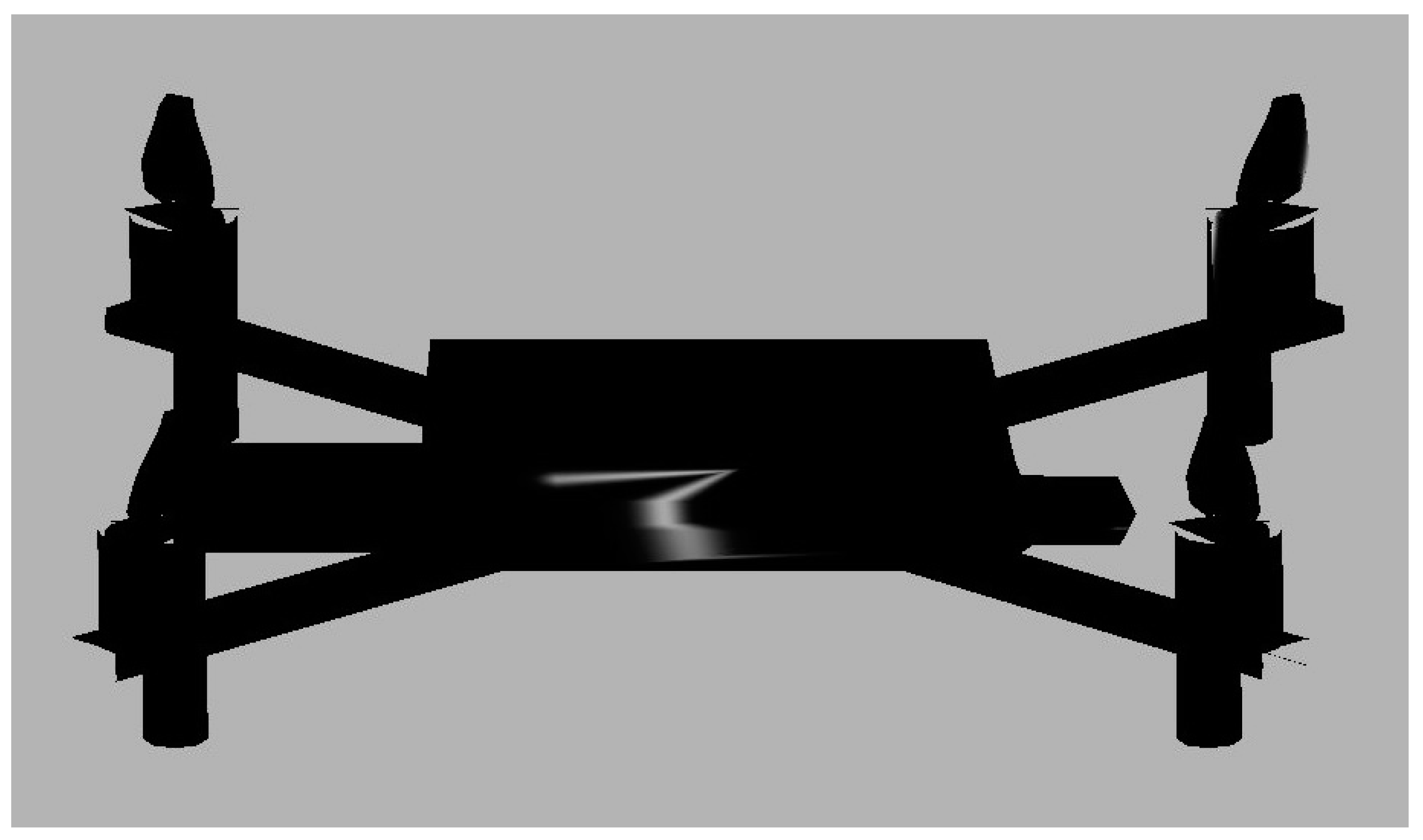
3.1. Design of Virtual Quadcopter

A real quadcopter and a virtual quadcopter are required to run a MR simulation. The real quadcopter performs within an airfield, and the virtual quadcopter interacts and follows the real quadcopter on the simulation platform. In this work, X-Plane is the simulation platform. X-Plane is a computer flight simulator software, produced by the Laminar Research Company of USA. In this study, an F450 spider quadcopter (see Figure 2) with a Pixhawk flight controller was made in house and used as the real quadcopter. The specifications of the F450 spider quadcopter are listed in Table 1. A virtual quadcopter with the parameters of the real quadcopter is needed to run the simulation platform in X-Plane. In this work, Plane Maker software (version 10.51) [32] was used to design a virtual quadcopter with the specifications of the F450 spider quadcopter.
To make a virtual quadcopter in Plane Maker, we needed to design mainly five parts, i.e., the motors, propellers, fuselage, arms, and landing gears. Plane Maker consists of several sections which include fuselage, misc bodies, engine specs, landing gear, weight and balance, and visual texture regions. In this study, the fuselage section was used to design the fuselage of the quadcopter. The designed fuselage contained a central body part, rear tail portion, and camera holder, similar to a real quadcopter (F450 Spider). The arms of the quadcopter were designed using the “misc bodies” section. The section on “engine specs” was used to build the motors and propellers, using the real quadcopter’s motor and propeller parameters including maximum turn rate; power set, pitch, root, and chord of the propeller; and propeller radius. We used the section on “landing gear” to design the four skid type landing gears similar to a real quadcopter. The total weight of the quadcopter was set the same as a real quadcopter using the “weight and balance” section. For more visibility in X-Plane, here, we used the color black (because the color of the real quadcopter was black) for the virtual quadcopter using the “visual texture regions” section. The fully designed virtual quadcopter in Plane Maker is shown in Figure 3. Note that it was essential to place the designed virtual quadcopter in the X-Plane’s aircraft folder.

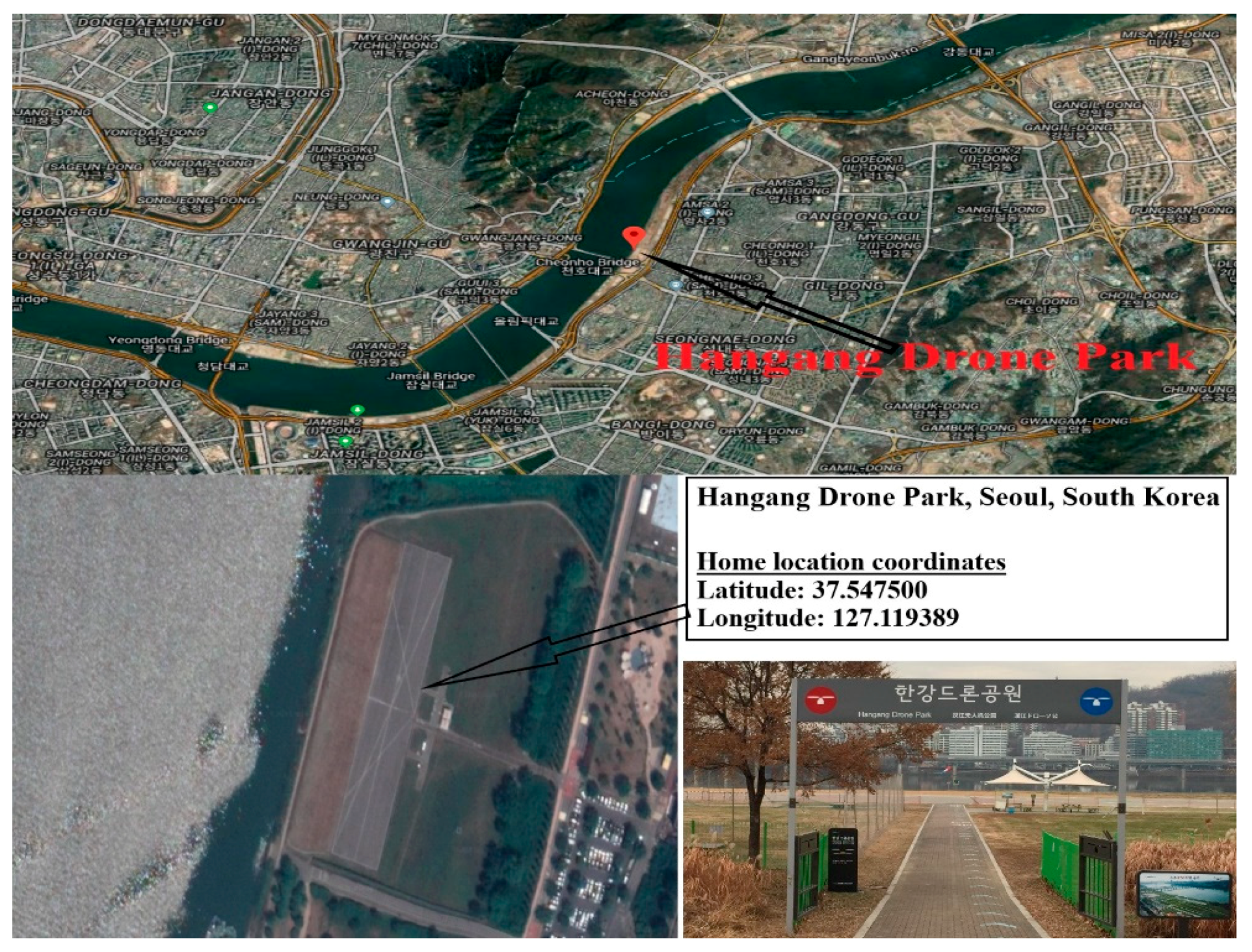
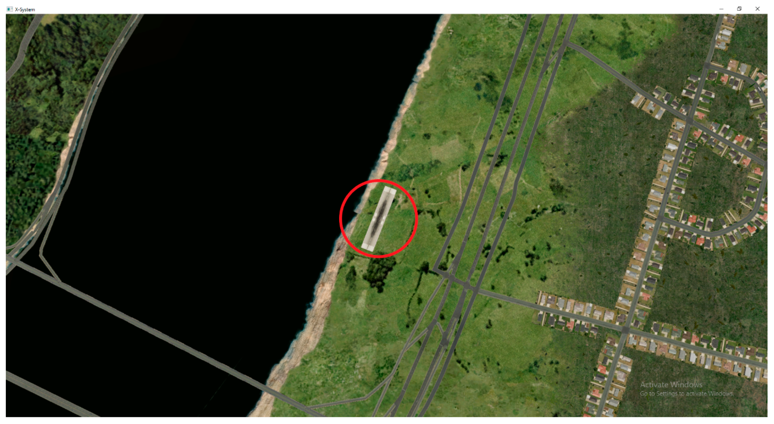
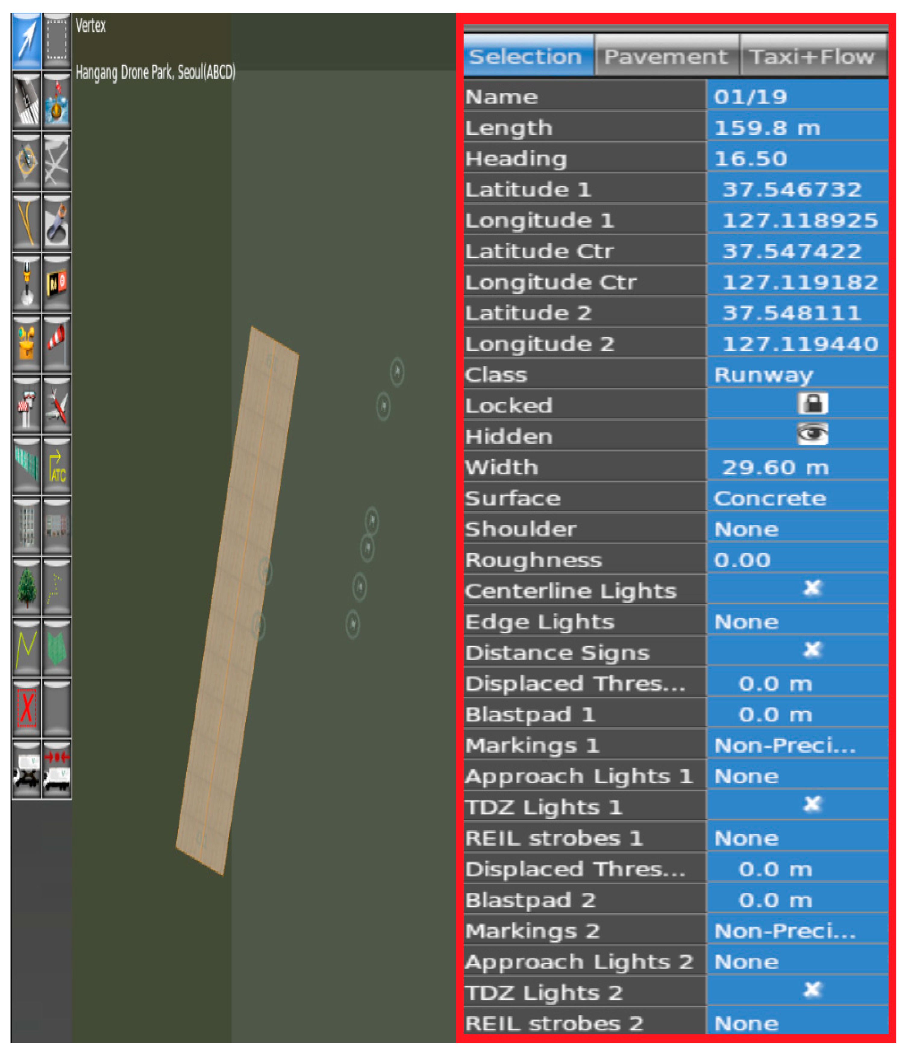
3.2. Design of the Simulation Environment (Virtual Location)

For the MR simulation, it was essential to design a virtual location in X-Plane similar to the location of the real quadcopter. In this work, a drone airfield was chosen in the permissible east part of Seoul, South Korea. Figure 4 illustrates the chosen airfield location (Hangang Drone Park) in Seoul, South Korea. Note that X-Plane has only the sceneries of major airports, there is no scenery available for the chosen airfield location (Hangang Drone Park). To overcome this lacuna, a new scenery of the chosen airfield location was designed at the same geographic location using WorldEditor (version: 1.7.2). WorldEditor is a software, which is used to create and edit the scenery for X-Plane.
Note that the small runway in the Hangang Drone Park (see Figure 4) was taken as the initial reference point of the real quadcopter. Therefore, we created a virtual runway similar to the real runway in Hangang Drone Park. In WorldEditor, first, we chose the “create airport” option. After selecting the create airport option, we could see several design tools on WorldEditor, including runway, helipad, objects, forest, sealane, and facades. Here, we used the “runway” tool to build the runway. According to latitude, longitude, heading, and a few other known design parameters highlighted in Figure 5, the virtual location was built similar to the chosen airfield location. Note that the coordinates of the virtual and actual locations needed to be exactly the same, which we achieved; otherwise, an error would occur during the MR simulation.
The designed virtual location was placed in the X-Plane environment (see Figure 6). Therefore, it was possible to fly the virtual quadcopter from the designed virtual location. Figure 7 illustrates the real and the virtual quadcopters in the real and the virtual environments, respectively (before MR simulation). In the following section, the interface between the real and the virtual quadcopters are presented.

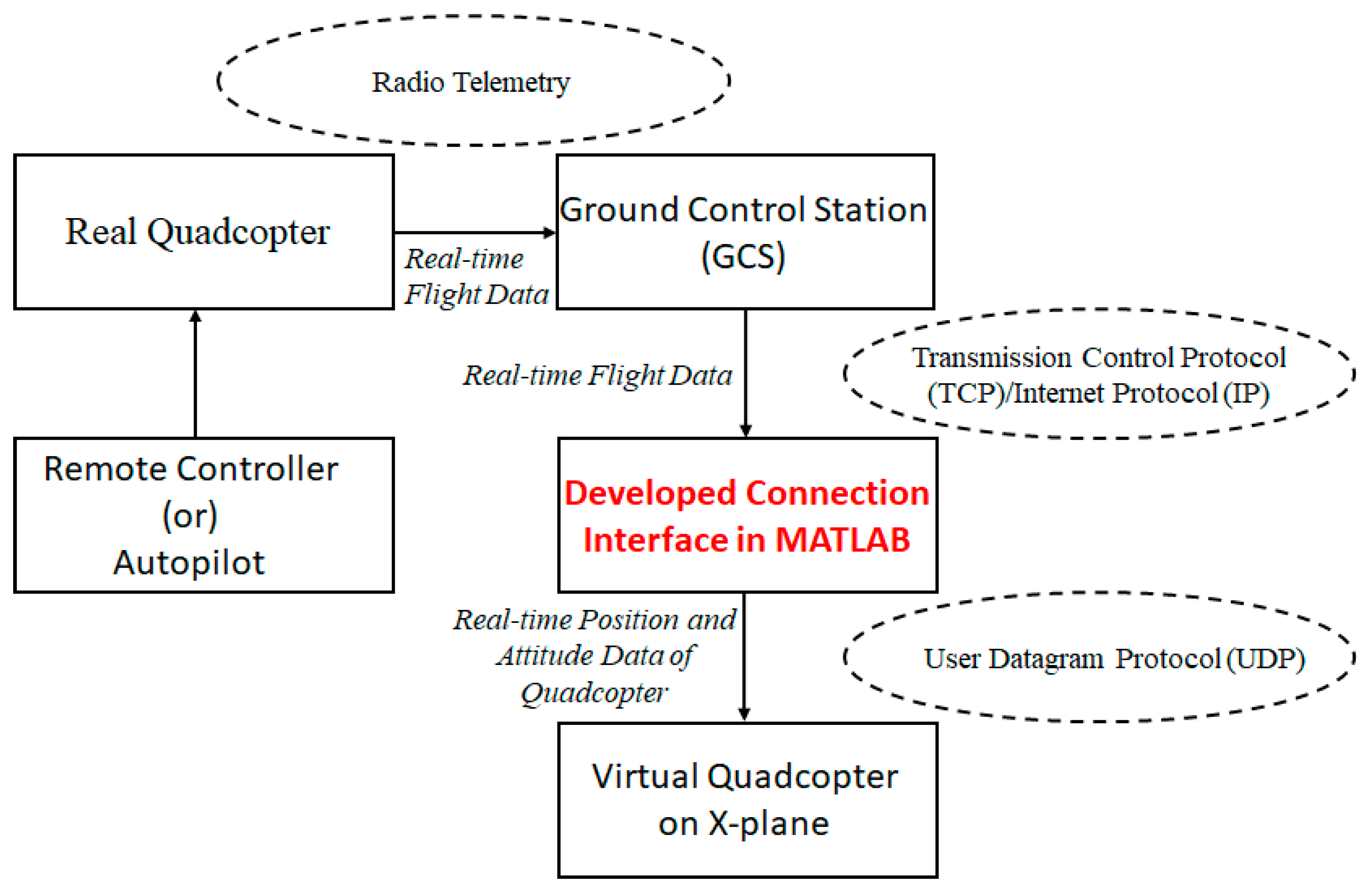
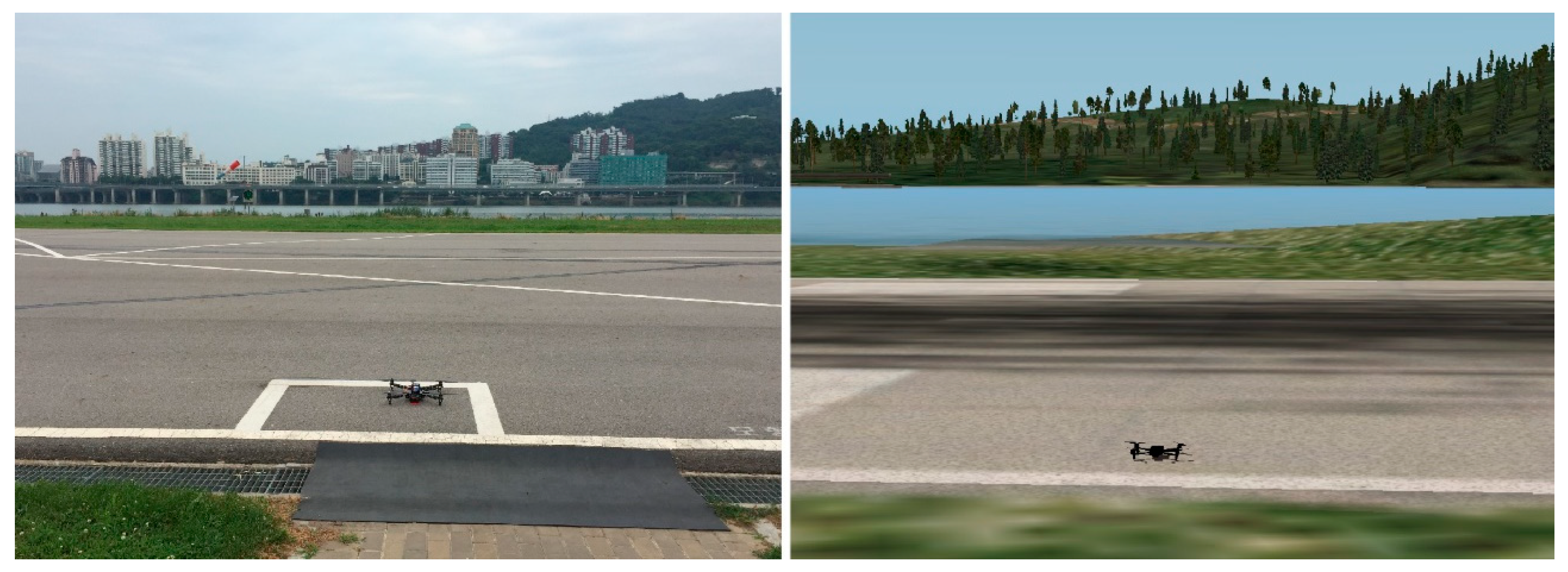
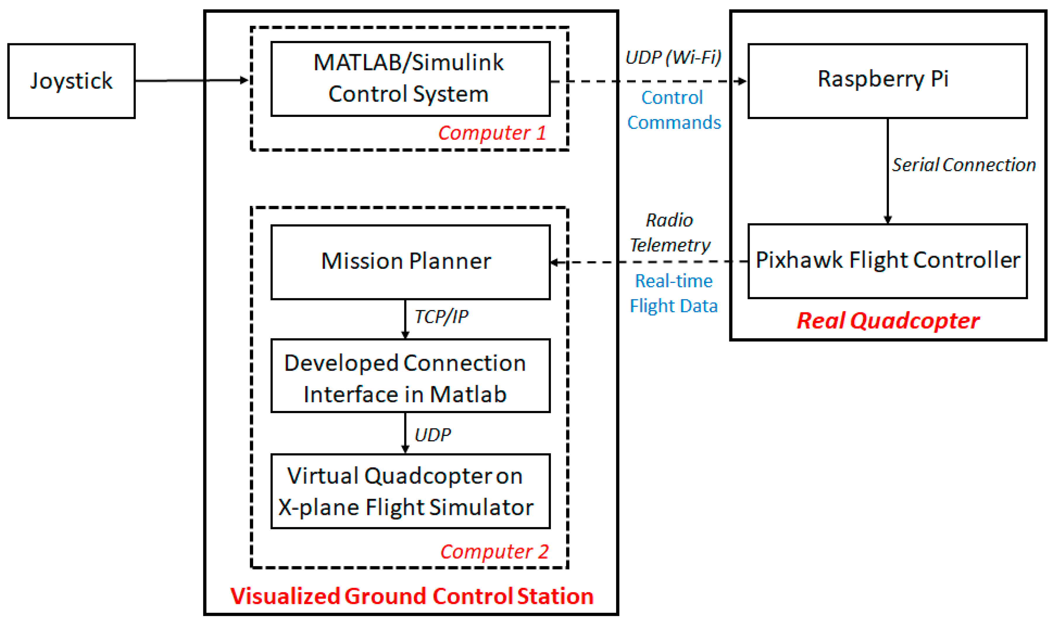
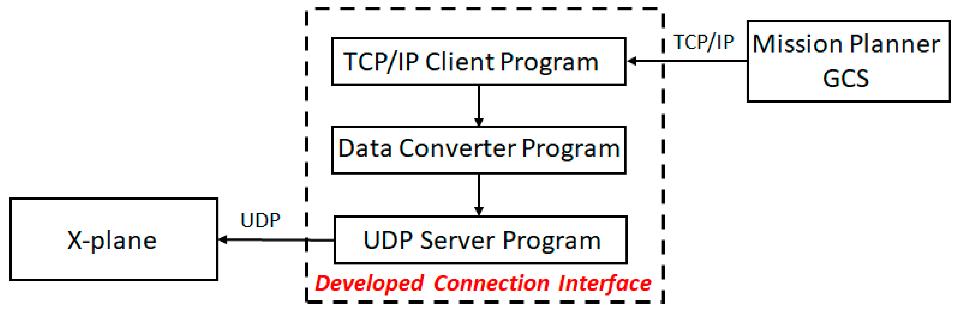
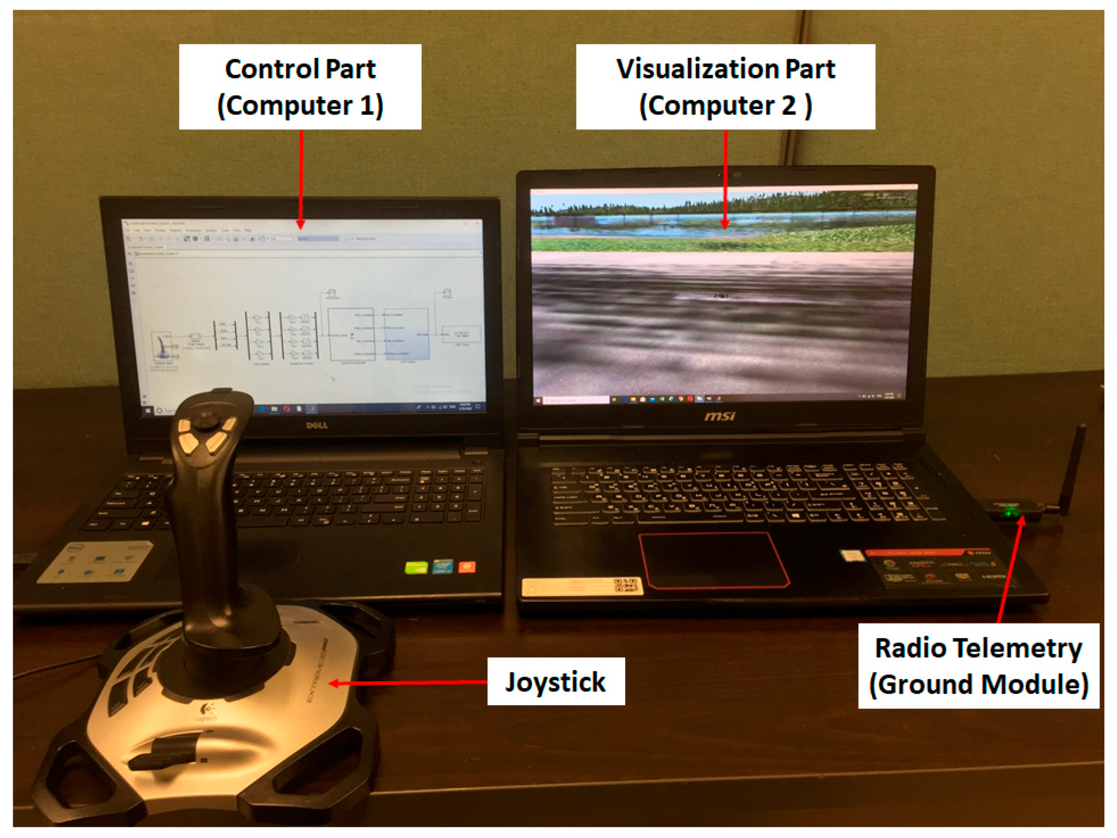
4. Interface between the Real and Virtual Quadcopters (Mixed Reality Simulation Setup)

The MR simulation makes a connection between the real and virtual quadcopters. Herein, we connected our real quadcopter to the ground control station (GCS) through a radio telemetry device. The radio telemetry device contains two parts; one is a ground module which is connected to the computer with GCS, and the second is an air module which is connected to the real quadcopter. Here, we used Mission Planner (version: 1.3.66) [33] as a GCS. Mission Planner is a GCS software for a plane, copter, and rover developed by Michael Osborne. Through the radio telemetry device, the real quadcopter sends real-time data to the Mission Planner GCS. As we mentioned previously, X-Plane is our simulation platform, so in this work, we developed a connection interface between X-Plane and the Mission Planner GCS in MATLAB for mixed reality simulation.
Figure 8 shows the MR simulation setup. The outline of the developed connection interface is shown in Figure 9. The developed connection interface is the combination of three MATLAB program sets, viz., TCP/IP client program, data converter program, and UDP server program. First, we set up Mission Planner as a TCP/IP server and the developed connection interface as a TCP/IP client. Then, Mission Planner sends the real quadcopter’s real-time flight data in the National Marine Electronics Association (NMEA) format.
Note that the NMEA is a standard data format supported by all GPS manufacturers [34]. The TCP/IP client program set in the developed connection interface collects the real-time NMEA formatted data from Mission Planner. The NMEA formatted data contains several interpreted sentences; the sentences contain the real-time flight data of the real quadcopter. The received NMEA formatted sentences are, GPGGA, GPGLL, GPHDG, GPVTG, GPRMC, and GPRPY. For MR simulation, we need only the real-time position and attitude data of the real quadcopter. Therefore, by using our data converter program (please see the link provided in the Supplementary Materials) set in the developed connection interface, we selected, split, and converted the GPGGA and GPRPY sentences from the NMEA formatted data, because the GPGGA sentence contains real-time latitude, longitude, and altitude data of the real quadcopter and the GPRPY sentence contains the real-time pitch, roll, and heading data of the real quadcopter. For the MR simulation, before running the program it is essential to set up X-Plane as the UDP client. Then, through the UDP server program set in the developed connection interface, the real-time latitude, longitude, altitude, pitch, roll, and heading data of the real quadcopter are sent to the X-Plane. Note that all the receiving, converting, and transmitting processes are in the real-time mode.

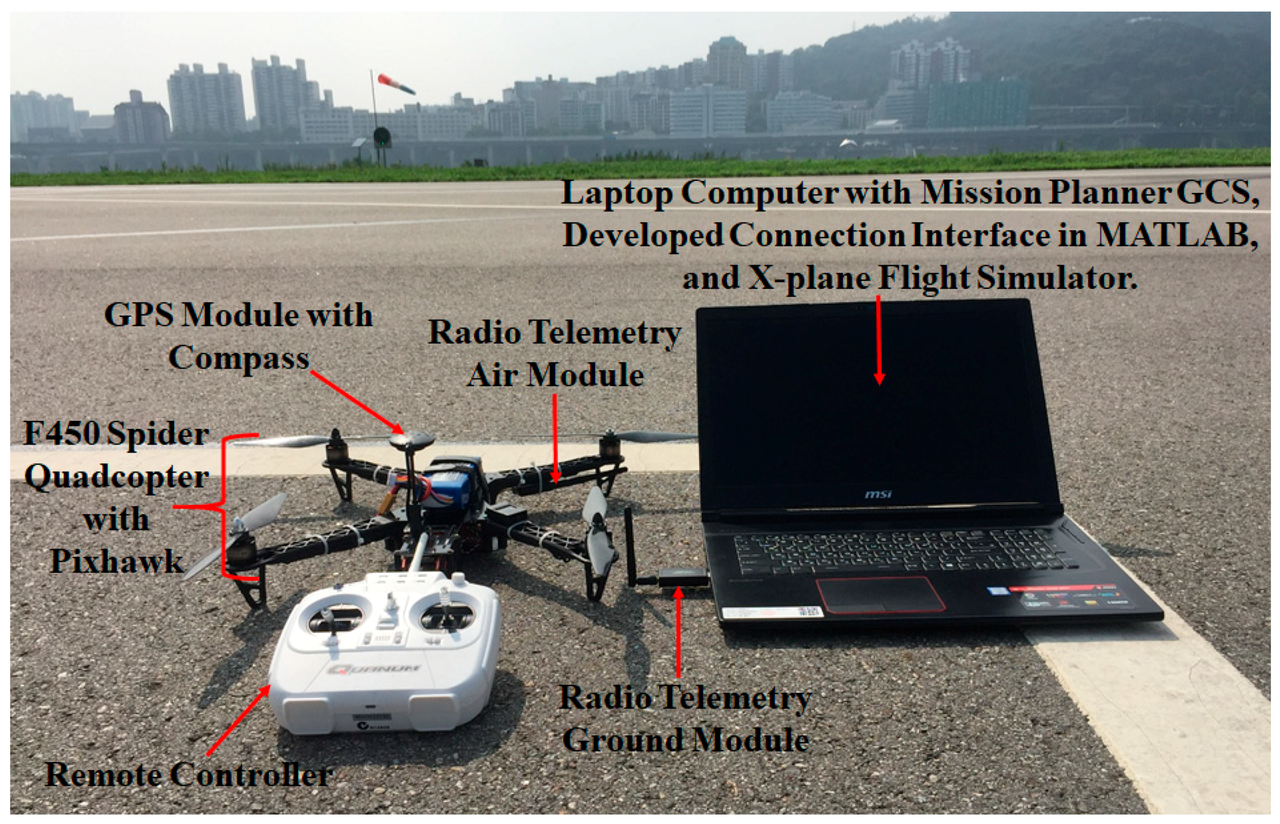
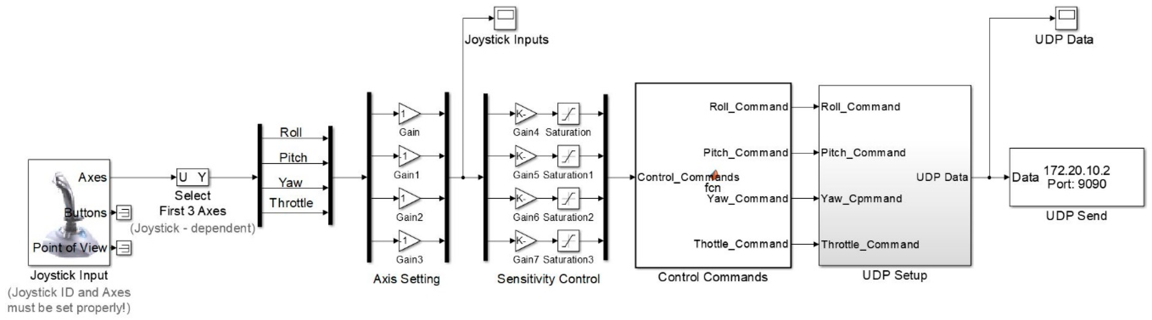
5. Visualized Ground Control Station for Quadcopter Using Mixed Reality Simulation

A ground control station (GCS) is an essential part of UAV flight, especially in the case of long-time missions. In this study, we developed a visualized GCS for a quadcopter UAV using a MATLAB/Simulink-based control system with our developed MR simulation technique. By using the visualized GCS, we controlled a quadcopter from a remote location, without a remote controller. Figure 10 illustrates the outline of the visualized GCS. In the first phase, we developed an open-loop control system in MATLAB/Simulink to control the quadcopter by a joystick. Note that for sending the control commands from the MATLAB/Simulink control system to the quadcopter, here, we attached a Raspberry Pi (Model 3 B+) single-board computer to the Pixhawk flight controller by a serial connection.
In the second phase, the MATLAB/Simulink control system sends the control commands (throttle, roll, pitch, and yaw command) to the Raspberry Pi. To do so, we developed a UDP interface in MATLAB/Simulink, which sent the control commands to Raspberry Pi via Wi-Fi. Figure 11 shows the control system with the UDP interface in MATLAB/Simulink. For communication between the Raspberry Pi and Pixhawk, here, we imported DroneKit-Python [35] in Raspberry Pi. DroneKit-Python is an open-source Python program package used to communicate with ArduPilot flight controllers, including Pixhawk. The DroneKit-Python coding in the Raspberry Pi sends the receiving control commands from the MATLAB/Simulink control system to Pixhawk.
In the third phase, we integrated our developed MR simulation technique with the control part for the visualization. The setup of the visualized GCS is shown in Figure 12. Note that the control part worked on a computer (Computer 1) with a joystick, and the visualization part ran on another computer (Computer 2) with the MR simulation setup. Therefore, instead of a remote controller, Computer 1 with the joystick controlled the quadcopter from a remote location using the visualization part on Computer 2.

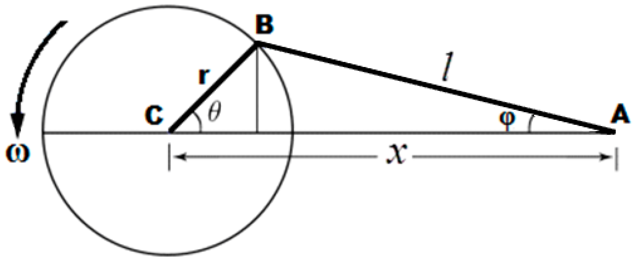
6. Design of the Quadcopter with Dual-Head Electromagnetic Propulsion Devices

The origin of the science of electromagnetic propulsion (EMP) does not fall on any individual, group or institution, but many investigators have found enormous applications in multidisciplinary areas. The principle of EMP is well known, as it accelerates a body using a streaming electrical current, either to charge a field or oppose a magnetic field for the propulsion application. Recently, V.R.Sanal Kumar et al., [36,37,38,39,40,41] designed an innovative dual-head electromagnetic propulsion and energy conversion system for planet landers and other various industrial applications. The dual-head electromagnetic (DHEM) energy conversion system is found unique for the soft landing of landers on any planet with a variable density atmosphere [39]. The quadcopter design, presented in this paper, is an offshoot of the above-mentioned DHEM energy conversion system developed for planet landers [39,40,41]. In this study, we demonstrated the capability of a new generation quadcopter UAV integrated with four dual-head EMP devices to spin the rotors with variable speeds and generate the desired lift force in the desired direction in any atmosphere, and further continuously steer the drone for planet surveillance. The uninterrupted exploration of the drone is achieved using the reciprocating moment of a magnetic piston facilitated with each EMP device with a solar-powered polarity changer timing circuit (PCTC) along with a laser-based timing circuit (LBTC) for redundancy during the night zone [36]. A dual-head EMP device is capable of generating an uninterrupted propulsive force for spinning the UAV rotors using a connecting rod and crankshaft mechanism by creating a reciprocating moment of the magnetic piston in a vacuum cylinder by varying the polarity of magnets for attraction and repulsion. Figure 13a shows the experimental qualification test setup of a dual-head EMP device. Figure 13b shows the physical model of the quadcopter UAV with the dual-head EMP devices. Figure 13c shows the design details of the electromagnetic head (EMH).Figure 14 shows the idealized physical model of an EMP device for creating variable spinning speeds for the UAV rotors for flying in a variable density environment without any lift loss. Figure 15 shows the geometric layout of the pin location (A) of the magnetic piston, the crankpin location (B), and the crank center (C).
The basic equation of the reciprocating magnetic piston system considered in Figure 14 is obtained as,
m p d 2 x p d t 2 μ q 1 q 2 4 π   x 2 p μ q 2 q 3   4 π   ( L T x p ) 2 = 0
d 2 x p d t 2 = μ 4 π   m p   [ q 1 q 2 x 2 p + q 2 q 3   ( L T x p ) 2 ]  
where q1, q2, and q3 are magnetic pole strength (see Figure 14), mp is the mass of the magnetic piston, and μ is the permeability.
From Figure 15, the angular velocity of the crankshaft (ω) of the EMP device can be obtained using Equation (3) as follows:
d x p d t + [ sin θ + sin 2 θ 2 ( l r ) 2 s i n 2   θ ]   ω   r = 0
The acceleration of the magnetic piston (dv/dt) can be obtained from Equation (4), as given below:
d v d t + r   ω 2 [ cos θ + ( l r ) 2 cos 2 θ + s i n 4   θ   ( ( l r ) 2 s i n 2   θ ) 3 / 2   ] = 0
where r is the crank radius, l is the rod length, ϴ is the crank angle from the top dead center, xp the axial position of the magnetic piston pin, t is the time, and v is the velocity of the magnetic piston (dxp/dt), which is obtained from Equation (3).

Mixed Reality Simulation with Dual-Head EMP Devices to Control the Quadcopter in Space

A literature review revealed that an autonomous rotorcraft is suitable for planets with an atmosphere, including Mars and Venus [4,36,37,38]. In this paper, we present the MR simulation with dual-head EMP devices for controlling the quadcopter during a space mission. Figure 16 shows the overview of the MR simulation technique with an EMP device to control the quadcopter in space. A GCS on Earth can communicate and control its device on any planet using the telemetry system. We developed an EMP device to control a quadcopter for a space mission based on the feedback system on atmospheric properties to the PCTC/LBTC controlled dual-head EMP devices. To control the EMP device from the GCS on Earth, we need a clear view and real-time performance of the space quadcopter. Therefore, here, we integrated our developed MR simulation technique with the GCS on Earth, then, using our MR simulation, we can see the clear view and real-time performance of the space quadcopter on our simulation platform (X-Plane). This preliminary study provides information for a real-time experiment with space agencies during the forthcoming planetary missions.

7. Results and Discussion

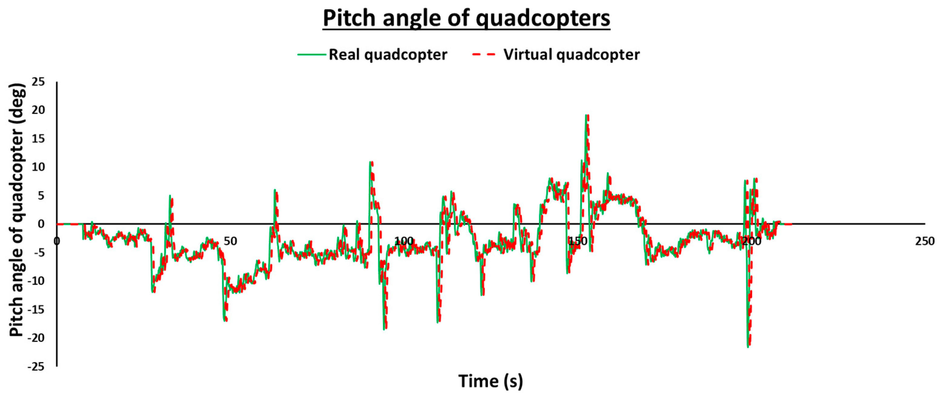
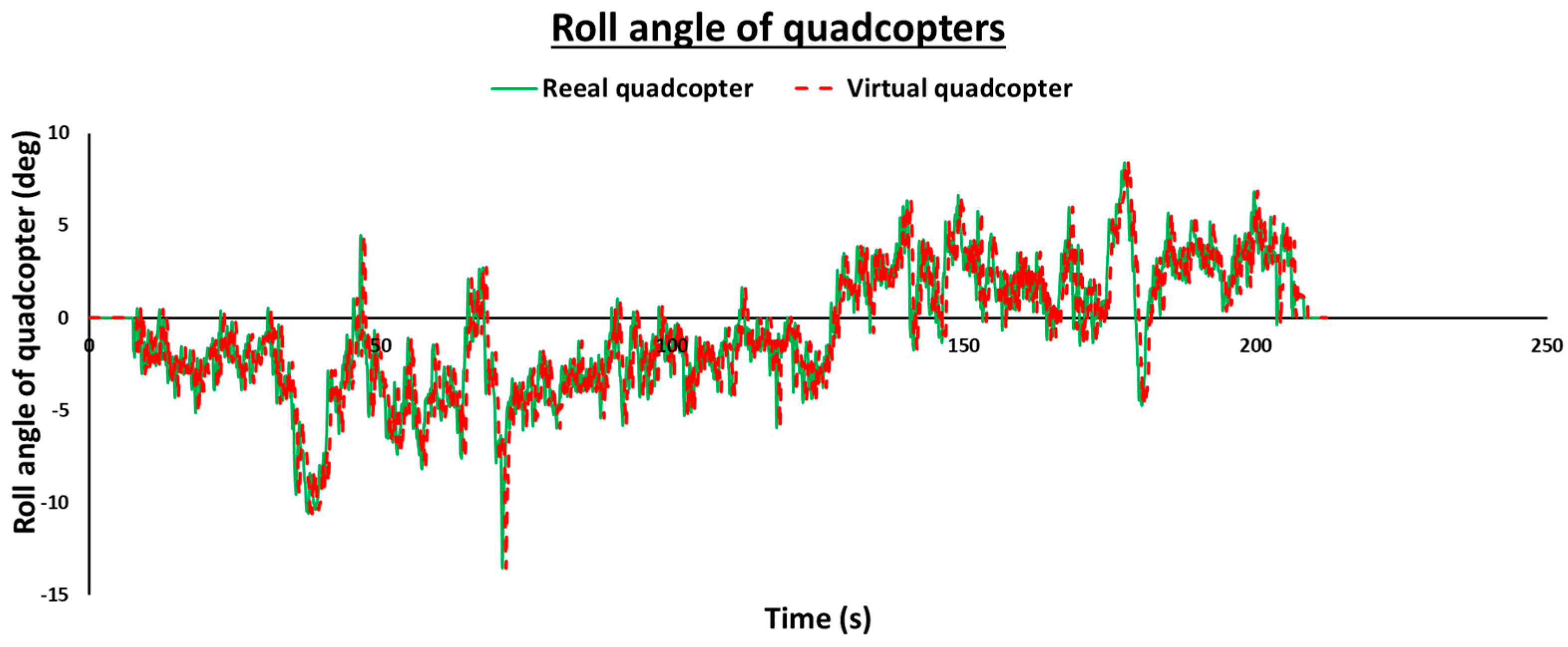
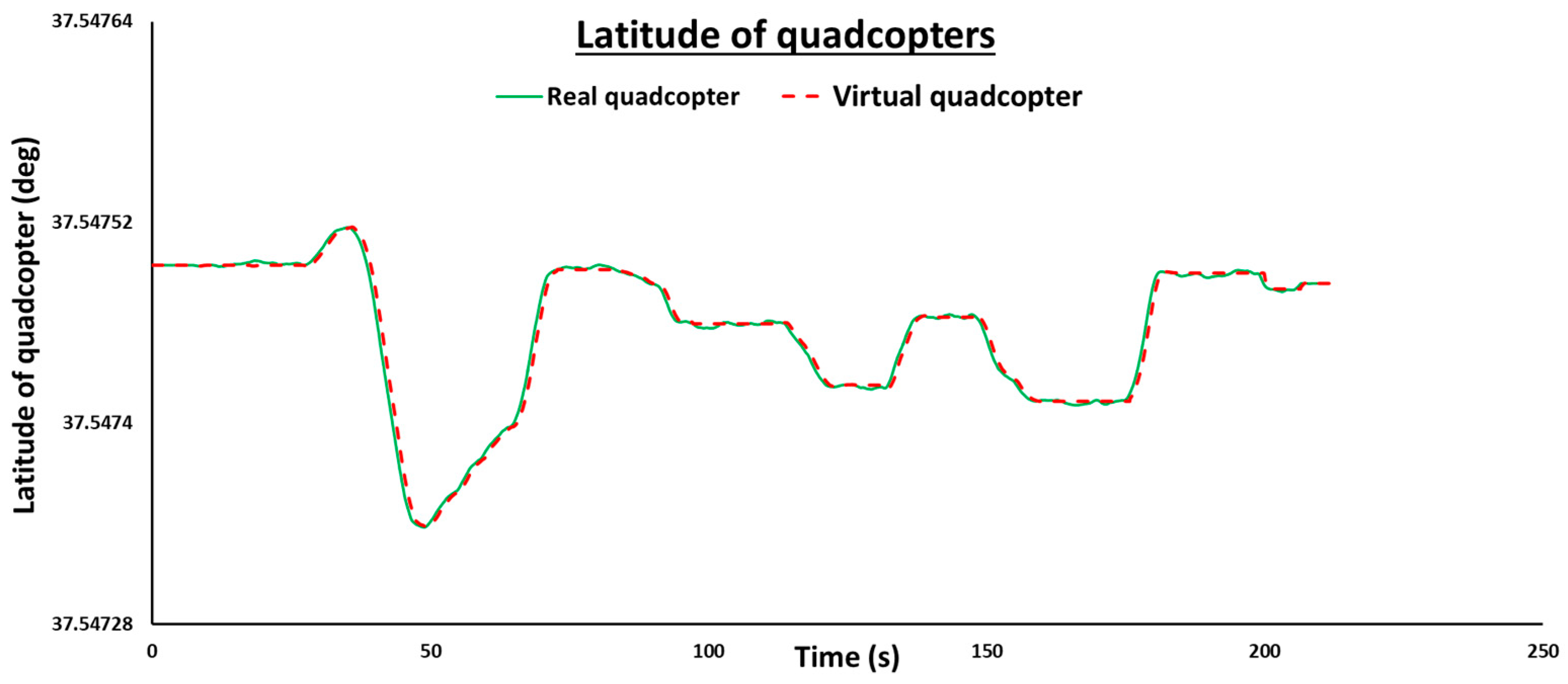
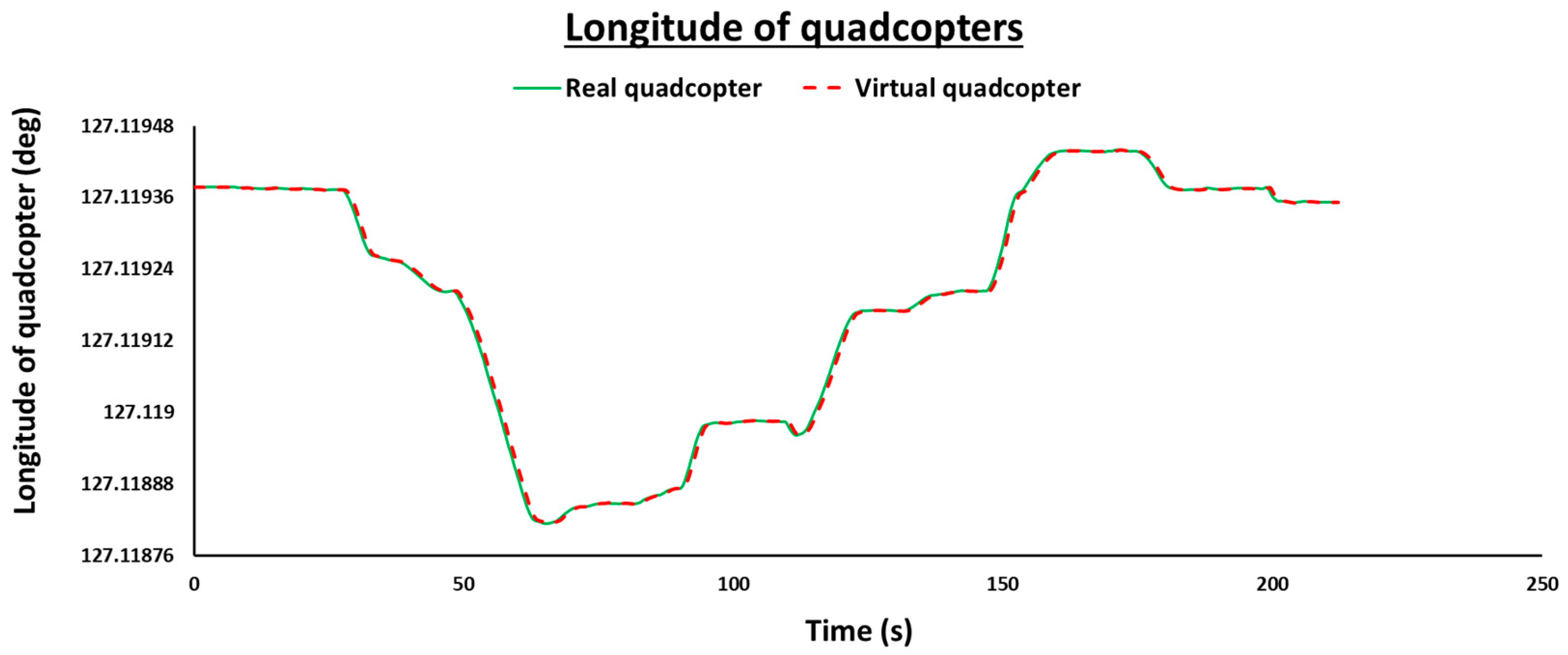
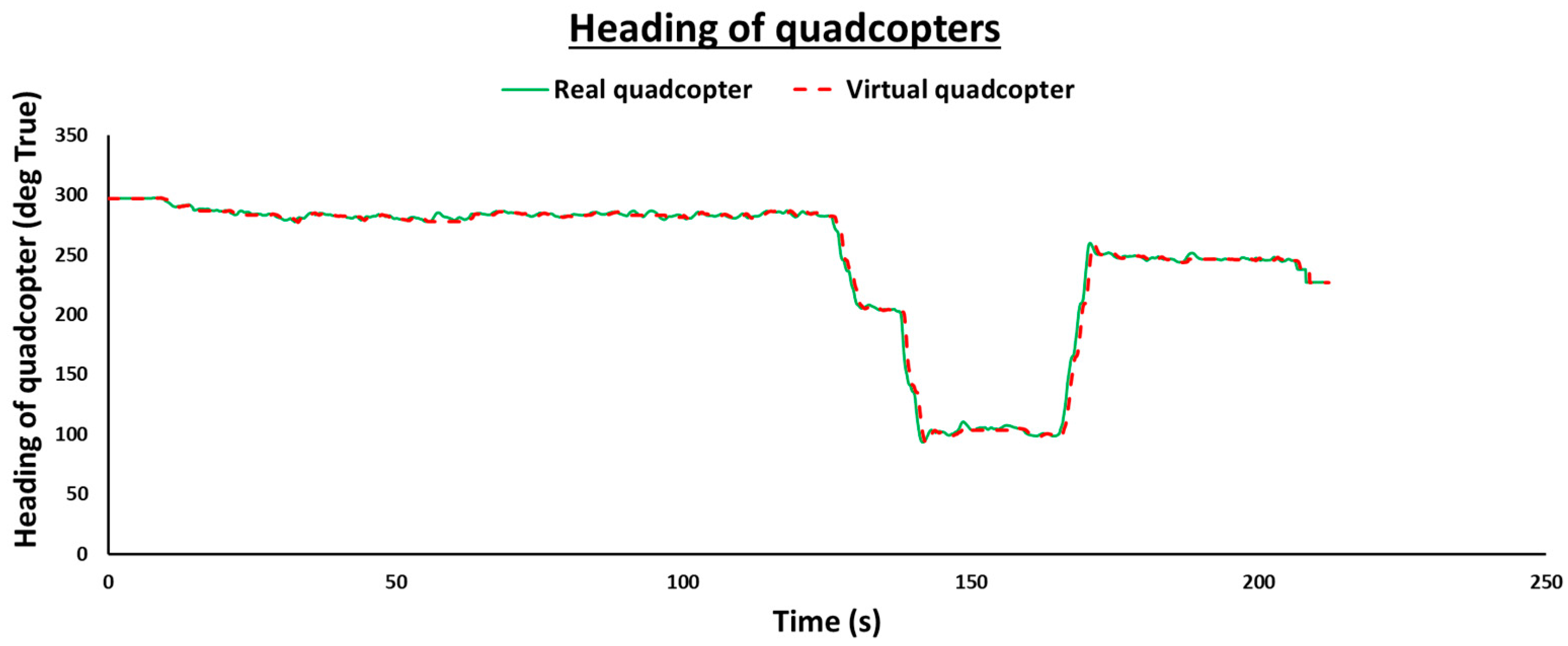
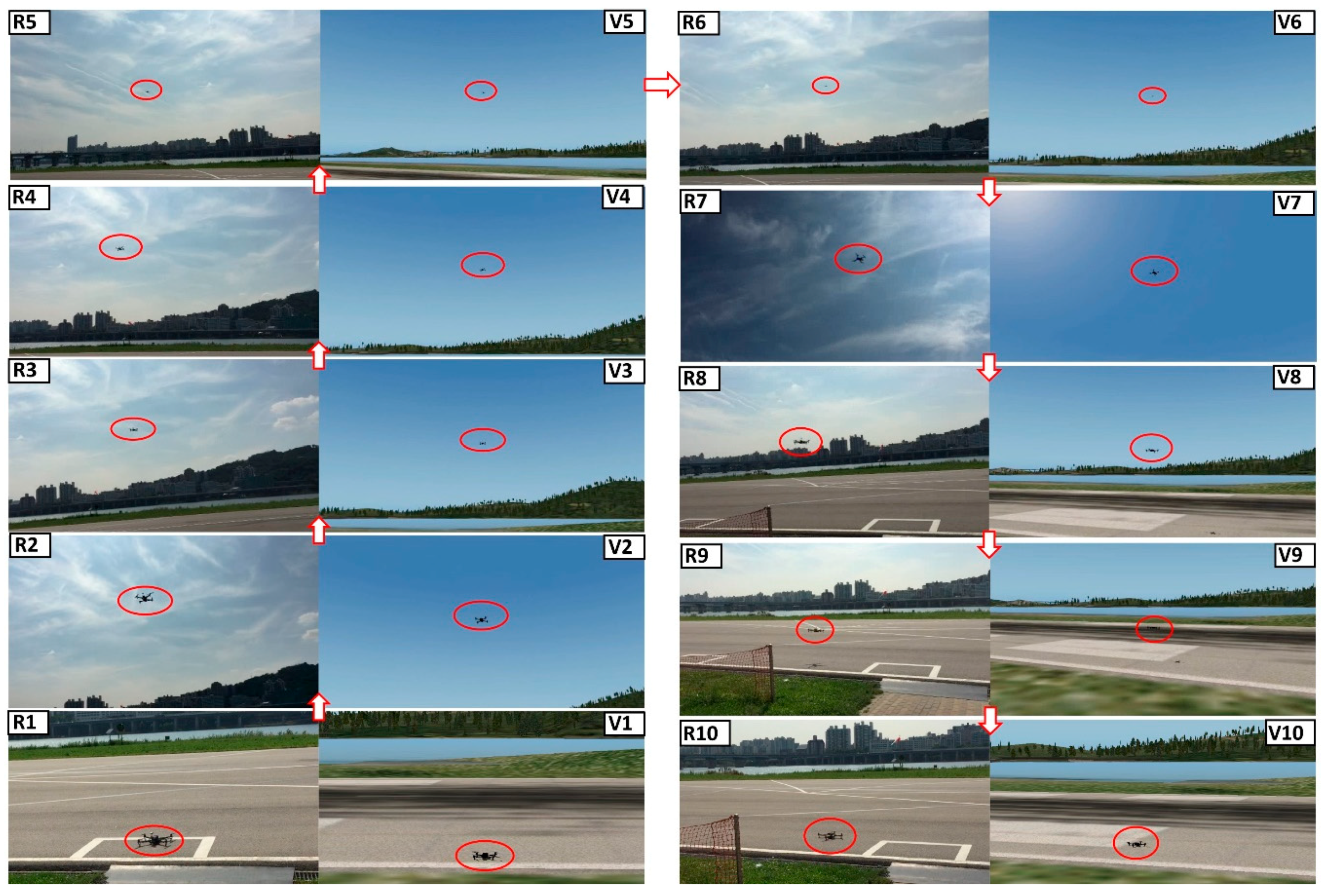
7.1. Validation of Mixed Reality Simulation

In this paper, for the MR simulation of the quadcopter, three flight tasks are performed. Figure 17, Figure 18 and Figure 19 represent the real-time flight trajectories of the real quadcopter in Mission Planner (the left side) and the real-time flight trajectories of the virtual quadcopter in X-Plane (the right side).
It can be seen from Figure 10, Figure 11 and Figure 12 that the flight trajectories from Mission Planner (real quadcopter) and X-Plane (virtual quadcopter) are similar, which means that the virtual quadcopter followed the real quadcopter. Note that in the real and virtual trajectories, there are some micro differences, due to tiny differences in the real and the virtual locations and these kinds of micro differences can be neglect in the simulation field. To validate the simulation, it is necessary to be more precise, thus, one should go through the data analysis using the Pixhawk’s data log file and the X-Plane’s data file.
The Mission Planner and X-Plane softwares have a data acquisition system that can record a wide range of parameters. The latitude, longitude, altitude, pitch angle, roll angle, and heading data are considered for data comparison. The data comparison procedure is shown in Figure 20. From the X-Plane’s data file, we can get flight data of the virtual quadcopter. In the case of the real quadcopter, we can get the flight data log file from Mission Planner or Pixhawk’s micro SD card in the real quadcopter.
Figure 21, Figure 22, Figure 23, Figure 24, Figure 25 and Figure 26 illustrate the flight data comparison of the real quadcopter and the virtual quadcopter. Here, we compared the flight data from Flight Task 1. The latitude, longitude, altitude, pitch angle, roll angle, and the heading comparison of the real and virtual quadcopters from Flight Task 1 are shown in Figure 21, Figure 22, Figure 23, Figure 24, Figure 25 and Figure 26, respectively. In Figure 21, Figure 22, Figure 23, Figure 24, Figure 25 and Figure 26, the continuous line indicates the real quadcopter’s data, and the broken line represents the virtual quadcopter’s data.
It is crystal clear from Figure 21, Figure 22, Figure 23, Figure 24, Figure 25 and Figure 26 that the real and the virtual quadcopters flight data are almost the same at every point of Flight Task 1. A comparison of the results shows that the latitude, longitude, and altitude of both quadcopters are nearly the same, which corroborates that the positions of both quadcopters are almost the same. The attitude comparison results (pitch angle, roll angle, and heading) of both quadcopters are also approximately equal. From the flight data comparison, we observed that on average a 400 ms time delay occurred in this MR simulation. Note that, if we observe the comparison results very precisely, we can see very tiny differences in the real and the virtual quadcopters’ data which are due to the small time-delay. In the simulation field, we can neglect the small time-delay, and the tiny differences based on our allowable bandwidth.
Figure 27 shows the MR simulation of the quadcopter in real time (Flight Task 1). The stages 1 to 10 denoted (see Figure 27) that the full flight of the quadcopter (from take-off (1) to landing (10)) with precision close to a prescribed target was met. From Figure 27, we can see, by using our proposed architecture, that the virtual quadcopter in X-Plane (V series in the figure) followed the real quadcopter (R series in the figure) in real time. Therefore, here, the virtual quadcopter interacted with the real quadcopter in real time, and the MR simulation was carried out. In Figure 27, for the virtual part, we used Still Spot view in X-Plane, note that we could use different views on X-Plane including Chase, Panel, Circle, Free-Camera, and Linear Spot.
The comparison results from Figure 21, Figure 22, Figure 23, Figure 24, Figure 25, Figure 26 and Figure 27 and the video in Supplementary Materials show that the performances of both quadcopters are almost identical in each and every point in the prescribed trajectory. Thereby, we could establish, herein, that using our developed architecture, the virtual quadcopter has interacted and followed the real quadcopter in real time. It proves conclusively that the MR simulation of a quadcopter is successfully achieved and validated.
By using our proposed MR simulation technique, we could see the clear view and the real-time performance of the real quadcopter on the simulation platform (X-Plane), which could possibly solve the visibility problems during a long-time mission.

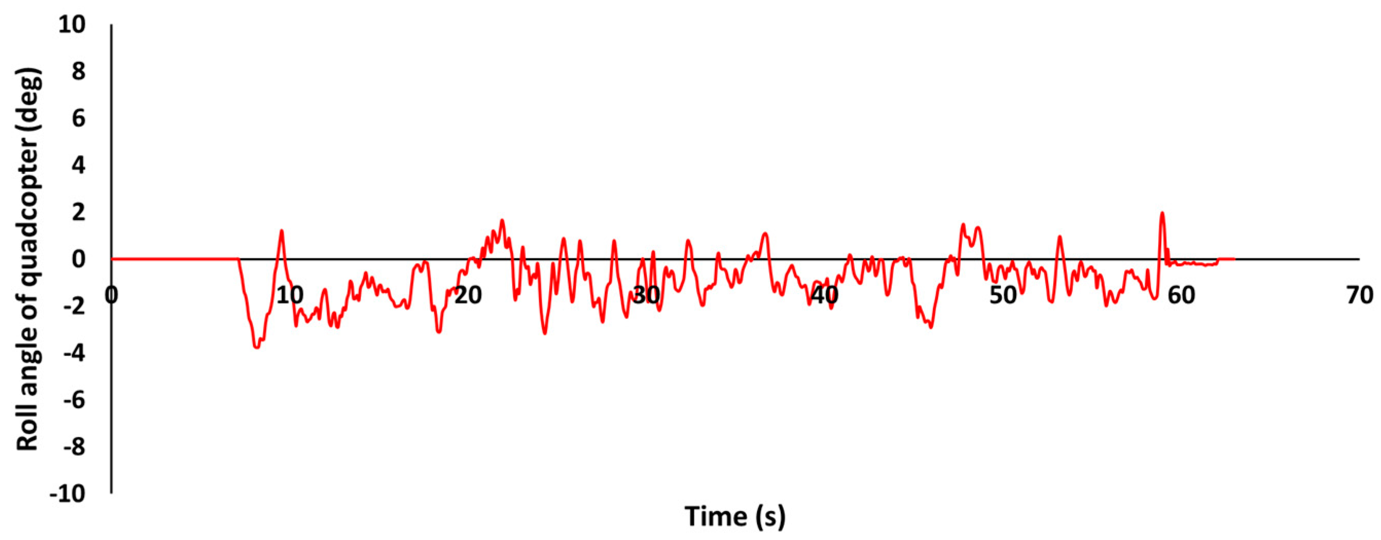
7.2. Validation of Visualized Ground Control Station

For the validation and the stability check, we conducted a vertical takeoff and landing test of the quadcopter using visualized GCS. The latitude, longitude, altitude, heading, roll angle, and pitch angle of the quadcopter during the vertical takeoff and landing is illustrated in Figure 28, Figure 29, Figure 30, Figure 31, Figure 32 and Figure 33, respectively.
From Figure 28 and Figure 29, we can see that there is only a marginal difference in latitude and longitude position of the quadcopter from the initial stage to the final stage, during the vertical takeoff and landing. The heading changes that occurred in the quadcopter are also small (see Figure 31) and, both roll and pitch angle changes are between −4 to 4 degrees (see Figure 32 and Figure 33). Note that the soft landing of any quadcopter flight is truly a difficult task, which we overcame in this study. Figure 30 shows that we landed our quadcopter safely using the visualized GCS. For the safe and soft landing, we took almost 22 s from around a 9 m height.
Figure 28, Figure 29, Figure 30, Figure 31, Figure 32 and Figure 33 show that the performance of the quadcopter during the vertical takeoff and landing was stable using the visualized GCS. Figure 34 illustrates the comparison of the pictures of the real and visualization part during the vertical takeoff and landing of the quadcopter. Due to the distance limitation of the Wi-Fi network connectivity, the distance between the visualized GCS and the quadcopter was restricted herein to 20 m. If we use an interconnecting network system, we can use the developed visualized GCS for long-distance missions. The total time delay of the system, including the visualization part was approximately 420 ms.

7.3. Validation of the Quadcopter with Electromagnetic Propulsion Devices

We have designed and laboratory tested a dual-head EMP device and qualified to integrate it with dual-head EMP devices for the next generation quadcopter UAV [40,41]. The flight experiment of a quadcopter UAV with four EMP devices and its MR simulation is beyond the scope of this paper.

8. Conclusions and Future Work

In this paper, we designed and laboratory tested a dual-head electromagnetic propulsion device for the new generation high-endurance quadcopter drone for lucrative earth and other planetary explorations. The beauty and novelty of this model comes from the fact that the proposed quadcopter can fly in an unknown environment without any lift loss for a longer duration than any existing design in the world. The fact is that a feedback control system is invoked for regulating the spinning speed of each rotor separately to retain the predetermined flight path and its hovering uninterruptedly in accordance with the density of the local atmosphere of the planet. In the case of any unexpected vacuum bubbles experienced during the surveillance, the feedback control system regulates the rotors to steer the drone in a favorable region through the polarity changer timing circuit and laser-based timing circuit. We conclude that the proposed new generation quadcopter drone integrated with lightweight electromagnetic propulsion devices is a viable option for achieving high-endurance with improved payload capability for earth and other planetary exploration with the aid of a mixed-reality simulation to meet the flight path demands of the mission. Using the base model of a drone, in this study, we developed a visualized ground control station using a Matlab/Simulink-based control system with mixed reality simulation. Additionally, we addressed mixed reality simulation based on a quadcopter and the X-Plane flight simulator. Through our comprehensive studies, mixed reality simulation is verified and validated. Herein, we connected the real quadcopter to the Mission Planner ground control station, through a radio telemetry device. Thereby, the real quadcopter could send real-time flight data to the Mission Planner. Note that we used X-Plane as the simulation platform. For mixed reality simulation, we developed a connection interface between Mission Planner and X-Plane in MATLAB. By using the developed connection interface, the virtual quadcopter in X-Plane could follow the real quadcopter in real time. The flight data from both quadcopters were gathered and compared. The comparison results show that the flight data from the real and the virtual quadcopters were almost the same at every point. In addition, we could see a similar flight trajectory from both quadcopters. Therefore, we concluded that the virtual quadcopter in X-Plane interacted and followed the real quadcopter in real time, which means that mixed reality simulation of the quadcopter UAV was executed and validated herein.
By using mixed reality simulation, we developed and tested a visualized ground control station that could control a quadcopter from a remote location, without a remote controller. Finally, in this phase, we introduced our mixed reality simulation technique with a dual-head electromagnetic propulsion device to control the quadcopter in any planet atmosphere. The real-time space flight experiment of a quadcopter drone with four electromagnetic propulsion devices and its mixed reality simulation is beyond the scope of this paper. However, it will be executed with the support of the space agencies worldwide, in the next phase of our work.
Note that, in this mixed reality simulation, we mainly focused on the interactions and performances of both quadcopters. In future work, we plan to consider more accurate scenery, weather conditions, and real-time movement of other objects, and also develop a ground control station for mixed reality simulation instead of the Mission Planner. We envision the advent of a new era of drones, a popular nickname for UAVs, that can autonomously fly in natural and man-made environments [41,42] with dual-head electromagnetic propulsion devices for a longer duration in any planet with high payload capability. Briefly, this paper provides insight for a credible mixed reality simulation for Mars explorations using quadcopter drones regulated by dual-head electromagnetic propulsion devices through multiple channel ultra-high speed wireless communication systems.

Supplementary Materials

The following are available online at https://www.mdpi.com/2076-3417/10/11/3736/s1, please see the video “MRS” provided herein for corroborating our claims on the mixed reality simulation of quadcopter UAV. Data converter program is available at https://github.com/ashishkumar2025/Data-converter-program-in-MATLAB.git.

Author Contributions

Conceptualization, A.K.; Methodology, A.K.; Experimental design, A.K.; Manuscript preparation, A.K.; Supervision, S.Y.; Review and editing, V.R.S.K. All authors have read and agreed to the published version of the manuscript.

Funding

This research was supported by the Agency for Defense Development, regarding the project of Design Study of Electronic Warfare Based on Modeling and Simulation

Acknowledgments

We thank our colleagues, Dong Cho Shin from the Agency for Defense Development and Ki Byung Jin from the LIG Nex1 Co., Ltd., who provided insight and expertise that greatly assisted the research, without prejudice to the final outcome of this manuscript.

Conflicts of Interest

The authors declare no conflict of interest.

References

  1. Alkamachi, A.; Erçelebi, E. A proportional derivative sliding mode control for an overactuated quadcopter. Proc. Inst. Mech. Eng. J. Part G Aerosp. Eng. 2018, 233, 1354–1363. [Google Scholar] [CrossRef]
  2. Kumar, A.; Yoon, S. Development of fast and soft landing system for quadcopter drone using fuzzy logic technology. Int. J. Adv. Trends Comput. Sci. Eng. 2019, 9, 624–629. [Google Scholar] [CrossRef]
  3. Lee, K.; Kim, Y.; Hong, Y. Real-time swarm search method for real-world quadcopter drones. Appl. Sci. 2018, 8, 1169. [Google Scholar] [CrossRef] [Green Version]
  4. Hassanalian, M.; Rice, D.; Abdelkefi, A. Evolution of space drones for planetary exploration: A review. Prog. Aerosp. Sci. 2018, 97, 61–105. [Google Scholar] [CrossRef]
  5. Lemke, L.G.; Heldmann, J.L.; Young, L.A.; Gonzales, A.A.; Gulick, V.C.; Foch, R.E.; Marinova, M.M.; Gundlach, J.F. Vertical takeoff and landing UAVS for exploration of recurring hydrological events. In Proceedings of the Concepts and Approaches for Mars Exploration, Houston, TX, USA, 12–14 June 2012. [Google Scholar]
  6. Colozza, A. Overview of innovative aircraft power and propulsion systems and their applications for planetary exploration. In Proceedings of the International Air and Space Symposium and Exposition cosponsored by the American Institute of Aeronautics and Astronautics, Dayton, OH, USA, 14–17 July 2003. [Google Scholar]
  7. Rabah, M.; Rohan, A.; Talha, M.; Nam, K.; Kim, S.H. Autonomous vision-based target detection and safe landing for UAV. Int. J. Control Autom. Syst. 2018, 16, 3013–3025. [Google Scholar] [CrossRef]
  8. Meier, L.; Tanskanen, P.; Fraundorfer, F.; Pollefeys, M. PIXHAWK: A system for autonomous flight using onboard computer vision. In Proceedings of the IEEE International Conference on Robotics and Automation, Shanghai, China, 9–13 May 2011; pp. 2992–2997. [Google Scholar]
  9. Nguyen, K.D.; Ha, C. Development of hardware-in-the-loop simulation based on Gazebo and Pixhawk for unmanned aerial vehicles. Int. J. Aeronaut. Space Sci. 2018, 19, 238–249. [Google Scholar] [CrossRef]
  10. Lyu, X.; Gu, H.; Zhou, J.; Li, Z.; Shen, S.; Zhang, F. Simulation and flight experiments of a quadrotor tail-sitter vertical take-off and landing unmanned aerial vehicle with wide flight envelope. Int. J. Micro Air Veh. 2018, 10, 303–317. [Google Scholar] [CrossRef] [Green Version]
  11. Liu, D.; Hou, Z.; Gao, X. Flight modeling and simulation for dynamic soaring with small unmanned air vehicles. Proc. Inst. Mech. Eng. J. Part G Aerosp. Eng. 2016, 231, 589–605. [Google Scholar] [CrossRef]
  12. Susini, A. A technocritical review of drones crash risk probabilistic consequences and its societal acceptance. In Proceedings of the Risk Information Management, Risk Models, and Applications (RIMMA) Conference, Berlin, Germay, 17–18 November 2014; pp. 27–38. [Google Scholar]
  13. Asim, M.; Ehsan, D.R.N.; Rafique, K. Probable causal factors in UAV accidents based on human factor analysis and classification system. In Proceedings of the 27th Congress of the International Council of the Aeronautical Sciences, Nice, France, 19–24 September 2010; pp. 4881–4886. [Google Scholar]
  14. Williams Kevin, W. A Summary of Unmanned Aircraft Accident/Incident Data: Human Factors Implications; Final Report; U.S. Department of Transportation (FAA): Washington, DC, USA, 2004. [Google Scholar]
  15. Kumar, A.; Mondon, C.; Yoon, S. Development of mixed reality simulation based on an unmanned aerial vehicle. In Proceedings of the CHIRA 2019 3rd International Conference on Computer-Human Interaction Research and Applications, Vienna, Austria, 20–21 September 2019; pp. 89–96. [Google Scholar]
  16. Kumar, A. Mixed Reality Simulation Based on an Unmanned Aerial Vehicle and X-Plane Flight Simulator. Korea Patent 1,615,010,612, 23 December 2019. [Google Scholar]
  17. Garcia, R.; Barnes, L. Multi-UAV simulator utilizing X-plane. J. Intell. Robot. Syst. 2010, 57, 393–406. [Google Scholar] [CrossRef]
  18. Qi, J.; Liu, J.; Zhao, B.; Mei, S.; Han, J.; Shang, H. Visual simulation system design of soft-wing UAV based on FlightGear. In Proceedings of the 2014 IEEE International Conference on Mechatronics and Automation, Tianjin, China, 3–6 August 2014; pp. 1188–1192. [Google Scholar]
  19. Lugo-Cárdenas, I.; Flores, G.; Lozano, R. The MAV3DSim: A simulation platform for research, education and validation of UAV controllers. In Proceedings of the 19th International Federation of Automatic Control (IFAC) World Congress, Cape Town, South Africa, 24–29 August 2014; pp. 713–717. [Google Scholar]
  20. Almousa, O.; Prates, J.; Yeslam, N.; Gregor, D.M.; Zhang, J.; Phan, V.; Nielsen, M.; Smith, R.; Qayumi, K. Virtual reality simulation technology for cardiopulmonary resuscitation training: An innovative hybrid system with haptic feedback. Simul. Gaming 2019, 50, 6–22. [Google Scholar] [CrossRef]
  21. Hsu, K.; Wang, C.; Jiang, J.; Wei, H. Development of a real-time detection system for augmented reality driving. Math. Probl. Eng. 2015, 2015. [Google Scholar] [CrossRef]
  22. Stevens, J.; Kincaid, P.; Sottilare, R. Visual modality research in virtual and mixed reality simulation. J. Def. Model. Simul. 2015, 12, 519–537. [Google Scholar] [CrossRef]
  23. Lan, G.; Sun, J.; Li, C.; Ou, Z.; Luo, Z.; Liang, J.; Hao, Q. Development of UAV based virtual reality systems. In Proceedings of the 2016 IEEE International Conference on Multisensor Fusion and Integration for Intelligent Systems (MFI), Baden-Baden, Germany, 19–21 September 2016; pp. 481–486. [Google Scholar]
  24. Wang, S.; Chen, J.; Zhang, Z.; Wang, G.; Tan, Y.; Zheng, Y. Construction of a virtual reality platform for UAV deep learning. In Proceedings of the 2017 Chinese Automation Congress (CAC), Jinan, China, 20–22 October 2017; pp. 3912–3916. [Google Scholar]
  25. Wang, Y.; Huang, W.; Been-Lirn Duh, H. InspectAR: Unmanned aerial vehicle (UAV) with augmented reality (AR) technology. In Proceedings of the SA ‘16 SIGGRAPH ASIA 2016 Mobile Graphics and Interactive Applications, Macau, China, 5–8 November 2016. [Google Scholar] [CrossRef]
  26. Li, Y.-B.; Kang, S.-P.; Qiao, Z.-H.; Zhu, Q. Development actuality and application of registration technology in augmented reality. In Proceedings of the 2008 International Symposium on Computational Intelligence and Design, Wuhan, China, 17–18 October 2008; pp. 69–74. [Google Scholar]
  27. Selecký, M.; Jan, F.; Rollo, M. Communication architecture in mixed-reality simulations of unmanned systems. Sensors 2018, 18, 853. [Google Scholar] [CrossRef] [Green Version]
  28. Peña, F.L.; Deibe, A.; Orjales, F. On the initiation phase of a mixed reality simulator for air pollution monitoring by autonomous UAVs. In Proceedings of the 2017 9th IEEE International Conference on Intelligent Data Acquisition and Advanced Computing Systems: Technology and Applications (IDAACS), Bucharest, Romania, 21–23 September 2017. [Google Scholar] [CrossRef]
  29. Katragadda, S.; Benedict, A.M.; Deane, A. Stereoscopic mixed reality in unmanned aerial vehicle search and rescue. In Proceedings of the AIAA SciTech Forum, San Diego, CA, USA, 7–11 January 2019. [CrossRef]
  30. Bai, H.; Atiquzzaman, M.; Ivancic, W. QoS support in ARINC 664 P8 data networks: ATN applications over TCP/IP ground-to-ground subnetworks. J. Aerosp. Comput. Inf. Commun. 2006, 3, 374–387. [Google Scholar] [CrossRef]
  31. Wei, H.; Tung, Y.; Yu, C. Counteracting UDP flooding attacks in SDN. In Proceedings of the 2016 IEEE NetSoft Conference and Workshops (NetSoft), Seoul, Korea, 6–10 June 2016; pp. 367–371. [Google Scholar]
  32. Bittar, A.; de Oliveira, N.M.F.; de Figueiredo, H.V. Hardware-in-the-loop simulation with X-Plane of attitude control of a SUAV exploring atmospheric conditions. J. Intell. Robot. Syst. 2014, 73, 271–287. [Google Scholar] [CrossRef]
  33. Rahman, M.F.A.; Radzuan, S.M.; Hussain, Z.; Khyasudeen, M.F.; Ahmad, K.A.; Ahmad, F.; Ani, A.I.C. Performance of loiter and auto navigation for quadcopter in mission planning application using open source platform. In Proceedings of the 2017 7th IEEE International Conference on Control System, Computing and Engineering (ICCSCE), Penang, Malaysia, 24–26 November 2017; pp. 342–347. [Google Scholar]
  34. Park, B.; Lee, J.; Kim, Y.; Yun, H.; Kee, C. DGPS enhancement to GPS NMEA output data: DGPS by correction projection to position-domain. J. Navig. 2013, 66, 249–264. [Google Scholar] [CrossRef] [Green Version]
  35. Available online: https://dronekit-python.readthedocs.io/en/latest/about/index.html (accessed on 14 May 2020).
  36. Kumar, V.R.S.; Mariappan, A.; Sukumaran, A.; Lal, V.K.V.; John, J.; Kumar, A.; Yoon, S.; Rajeev, J. Design of an Uninterrupted Propulsion System for Spinning Planet Landers for Soft Landing. In Proceedings of the AIAA Scitech 2019 Forum, San Diego, CA, USA, 7–11 January 2019. [Google Scholar] [CrossRef]
  37. Mariappan, A.; Sukumaran, A.; Thianesh, U.K.; Sankar, P.G.; Kumar, A.; Yoon, S.; Kumar, V.R.S. Design of Planet Landers for Soft Landing with DHEM Propulsion System—Phase I. In Proceedings of the AIAA Propulsion and Energy 2019 Forum, Indianapolis, IN, USA, 19–22 August 2019. [Google Scholar] [CrossRef]
  38. Kumar, A.; Yoon, S.; Amrith, M.; Thianesh, U.K.; Kumar, V.R.S. Mixed reality simulation of a quadcopter with a DHEM device for planet landers for soft landing—A review. Int. J. Adv. Sci. Technol. 2019, 28, 157–171. [Google Scholar]
  39. Kumar, V.R.S.; Mariappan, A.; Thianesh, U.K.; Sukumaran, A.; Kumar, A.; Lal, V.K.V.; John, J. The Invention of an Electromagnetic Propulsion System for Drones and Plant Landers with an Unrestricted Flight Endurance. Nature 2020, in press. [Google Scholar]
  40. Kumar, V.R.S.; Lal, V.K.V.; Mariappan, A.; Sukumaran, A.; Kumar, A.; John, J.; Thianesh, U.K. Dual-Head Electromagnetic Propulsion and Energy Conversion System for Planet Landers and Other Various Industrial Application. India Patent 201,841,049,585, 28 December 2018. [Google Scholar]
  41. Kumar, V.R.S. Design and Testing of Dual-Head Electromagnetic Propulsion System for Spinning Venus Impact Probe; ISRO Space Based Experiments to Study Venus—A Proposal; No. VRS/KCT/ISRO/VIP-P1; ISRO Space Science Programme Office, ISRO HQ, Antariksh Bhavan: Bangalore, India, 2017. [Google Scholar]
  42. Floreano, D.; Robert, J.W. Science, technology and the future of small autonomous drones. Nature 2015, 521, 460–466. [Google Scholar] [CrossRef] [PubMed] [Green Version]
Figure 1. Data flow between the real and the virtual quadcopters (overview of mixed reality simulation).
Applsci 10 03736 g001
Figure 2. F450 spider quadcopter.
Applsci 10 03736 g002
Figure 3. Fully designed virtual quadcopter.
Applsci 10 03736 g003
Figure 4. Airfield location (Hangang Drone Park) in Seoul, South Korea.
Applsci 10 03736 g004
Figure 5. Design parameters of virtual location (on WorldEditor).
Applsci 10 03736 g005
Figure 6. Designed virtual location (Hangang Drone Park) in X-Plane.
Applsci 10 03736 g006
Figure 7. The real quadcopter in the real environment (Hangang Drone Park) (left) and the virtual quadcopter in the X-Plane’s virtual environment (designed Hangang Drone Park) (right).
Applsci 10 03736 g007
Figure 8. Mixed reality simulation setup.
Applsci 10 03736 g008
Figure 9. Outline of the developed connection interface.
Applsci 10 03736 g009
Figure 10. Overview of the visualized ground control station.
Applsci 10 03736 g010
Figure 11. Control system with user datagram protocol (UDP) interface in MATLAB/Simulink.
Applsci 10 03736 g011
Figure 12. Visualized ground control station (GCS) setup.
Applsci 10 03736 g012
Figure 13. (ac) Ground testing and design details of the quadcopter unmanned aerial vehicle (UAV) with dual-head EMP devices.
Applsci 10 03736 g013
Figure 14. An idealized physical model of a dual-head EMP device for the UAV.
Applsci 10 03736 g014
Figure 15. Geometric layout of the EMP device with a crankpin.
Applsci 10 03736 g015
Figure 16. Overview of the mixed reality simulation for the quadcopter space activates using a dual-head EMP device.
Applsci 10 03736 g016
Figure 17. Flight Task 1, flight trajectory of the real (left) and the virtual quadcopters (right).
Applsci 10 03736 g017
Figure 18. Flight Task 2, flight trajectory of the real (left) and the virtual quadcopters (right).
Applsci 10 03736 g018
Figure 19. Flight Task 3, flight trajectory of the real (left) and the virtual quadcopters (right).
Applsci 10 03736 g019
Figure 20. Data comparison procedure.
Applsci 10 03736 g020
Figure 21. Latitude comparison of the real and the virtual quadcopters.
Applsci 10 03736 g021
Figure 22. Longitude comparison of the real and the virtual quadcopters.
Applsci 10 03736 g022
Figure 23. Altitude comparison of the real and the virtual quadcopters.
Applsci 10 03736 g023
Figure 24. Pitch angle comparison of the real and the virtual quadcopters.
Applsci 10 03736 g024
Figure 25. Roll angle comparison of the real and the virtual quadcopters.
Applsci 10 03736 g025
Figure 26. Heading comparison of the real and the virtual quadcopters.
Applsci 10 03736 g026
Figure 27. Mixed reality simulation of the quadcopter (R series = real part and V series = virtual part).
Applsci 10 03736 g027
Figure 28. Latitude of the quadcopter during the vertical takeoff and landing.
Applsci 10 03736 g028
Figure 29. Longitude of the quadcopter during the vertical takeoff and landing.
Applsci 10 03736 g029
Figure 30. Altitude of the quadcopter during the vertical takeoff and landing.
Applsci 10 03736 g030
Figure 31. Heading of the quadcopter during the vertical takeoff and landing.
Applsci 10 03736 g031
Figure 32. Roll angle of the quadcopter during the vertical takeoff and landing.
Applsci 10 03736 g032
Figure 33. Pitch angle of the quadcopter during the vertical takeoff and landing.
Applsci 10 03736 g033
Figure 34. Picture of the real (left) part and the visualization part (right) during the vertical take-off and landing of the quadcopter.
Applsci 10 03736 g034
Table 1. Specifications of the F450 spider quadcopter.
Quadcopter SpecificationsModel/Values
Flight controllerPixhawk 2.4.8
Total mass (including battery)2 kg
Frame diagonal length450 mm
Propellers dimension and pitch10 × 3.8
No of blade2
Motor (brushless)2212–920 KV
Motor turn rate4000–9000 RPM
Radio telemetry433 MHZ

