Article

Snap-Through Buckling Mechanism for Frequency-up Conversion in Piezoelectric Energy Harvesting

1
Department of Civil and Environmental Engineering DICA, Politecnico di Milano, Piazza Leonardo Da Vinci, 32, 20133 Milan (MI), Italy
2
Department of Information Engineering, University of Brescia, via Branze 38, 25123 Brescia (BS), Italy
*
Author to whom correspondence should be addressed.
Appl. Sci. 2020, 10(10), 3614; https://doi.org/10.3390/app10103614
Submission received: 28 March 2020 / Revised: 13 May 2020 / Accepted: 19 May 2020 / Published: 23 May 2020

Abstract

:
This paper describes a piezoelectric energy harvester employing a snap-through buckling (STB) mechanism for frequency-up conversion (FuC). The harvester consists of two main components: a bistable mechanical structure and one piezoelectric cantilever beam. The device is designed by means of analytical methods and numerical simulations. A proof-of-concept prototype is manufactured and tested under low frequency mechanical excitation. Experimental results show that, if the STB is induced, from the second stable configuration back to the undeformed one, the FuC is obtained and the response of the beam presents frequency components in a wide range, even though the resonant frequency of the cantilever beam is not excited. The results are hence in agreement with the expected behavior: if the device, forced in the second stable configuration, is subject to a low-frequency excitation whose amplitude exceeds a threshold, STB is triggered and the ensuing FuC provokes a widening of the beam vibrations frequency range and consequently a significant effectiveness in terms of power output. A maximum power of 4 mW is obtained by using an optimal resistive load as STB from a stable configuration of the bistable mechanism to the other one is triggered; a maximum energy of 4.5 μ J is obtained in case of a rectifier circuit with storage capacitor.

1. Introduction

In recent years, energy harvesting (EH) has been the object of intensive investigations due to the ubiquity of natural unlimited energy sources which can be exploited, in particular the kinetic energy from ambient vibrations [1,2,3,4,5,6,7,8,9]. This and the recent progresses in the microelectronics and MEMS (Micro Electro-Mechanical System) field have made battery-less small electronic devices possible. As a matter of fact, the mechanical energy, by means of energy harvesters using different transduction mechanisms, can be scavenged and converted into electrical energy, which can be used to power electronic devices. One of the most common transduction mechanisms used in EH is based on the piezoelectric effect, due to higher energy density compared to electrostatic and electromagnetic conversion principles. Piezoelectric linear energy harvesters are generally manufactured as cantilever beams due to their high compliance and placed on a vibrating structure [10,11,12,13,14,15].
The mechanical energy from ambient vibrations is generally distributed over a broad frequency spectrum in which frequency components lower than few hundreds of hertz are typically dominant. However, linear harvesters have the maximum effectiveness when they are excited close to their resonant frequencies, which are generally higher than the frequency of ambient vibrations. As a consequence, this demands for bandwidth broadening, frequency translation, FuC, and non-resonant operation under non-sinusoidal or random excitation.
Different solutions have been proposed to make piezoelectric harvesters more effective, for instance exploiting nonlinear phenomena. Geometrical nonlinearities or interactions with external objects, for instance magnets, are exploited as passive tuning method to modify the dynamic behavior of the linear harvester. In [16,17], external magnets are employed to modify the stiffness and thus the resonant frequency of the piezoelectric cantilever beam. In [18], two magnets, placed close to the free end of a piezoelectric cantilever beam, are used to apply a force pulse on it and attain the FuC. Other harvesters exploit nonlinearities and can be modeled as Duffing oscillators [19,20,21]. In addition, strategies based on impact can be adopted [22,23]. Moreover, to increase the collected power, arrays of converters can be considered [24]; this approach demands for suitable management circuits to combine the outputs of the converters [25,26,27]. A phenomenon generally used to attain FuC is STB: bistable mechanical structures can be employed for the converter itself or for the host structure. In the first case, a piezoelectric pre-buckled bistable beam can be used instead of a cantilever beam, as suggested in [28,29,30]: when the magnitude of the mechanical excitation exceeds a certain threshold, which depends on the geometrical and mechanical characteristics of the pre-buckled structure, the beam switches between its two stable states allowing the widening of the operational frequency spectrum of the device. Conversely, a harvester belonging to the second category has been proposed in [31], where the concept was to exploit a beam axially loaded and buckled into a stable configuration, a proof mass, and an array of piezoelectric cantilever beams. Because of the occurrence of FuC, a maximum power of 41.7 μ W was obtained for each cantilever beam having a resonant frequency of about 230 Hz and with dimensions 15 mm × 4 mm × 0.2 mm, under a harmonic acceleration at a frequency of 15 Hz (see [31] for additional details).
The device presented in this paper belongs to the latter category: in detail, one piezolaminated cantilever beam is connected to a nonlinear bistable structure, which allows the triggering of FuC. Different from previous research, the bistable device does not rely on the presence of an axial force that could be difficult to achieve and mantain, especially for small-scale devices. The desired behavior is attained by manufacturing the structure with an intrinsecally bistable shape, leveraging the working principle adopted and patented in [32,33] for different purposes. As explained thoroughly in the following section, the specific initial shape of the system entails STB between two stable configurations, similarly to the case of shallow arches. The device addressed herein is designed and manufactured in a centimeter size. The idea is supported by analytical investigations and by Finite Element (FE) numerical analyses, carried out with the software ABAQUS (version R2018, Dassault Systèmes SIMULIA, Johnston, RI, USA). A set of different prototypes have been realized and thoroughly tested. Eventually, the effectiveness of the STB mechanism in triggering the FuC is experimentally validated by means of electrical measurements on the manufactured prototypes and compared to the FE results, with encouraging results.

2. STB Mechanisms

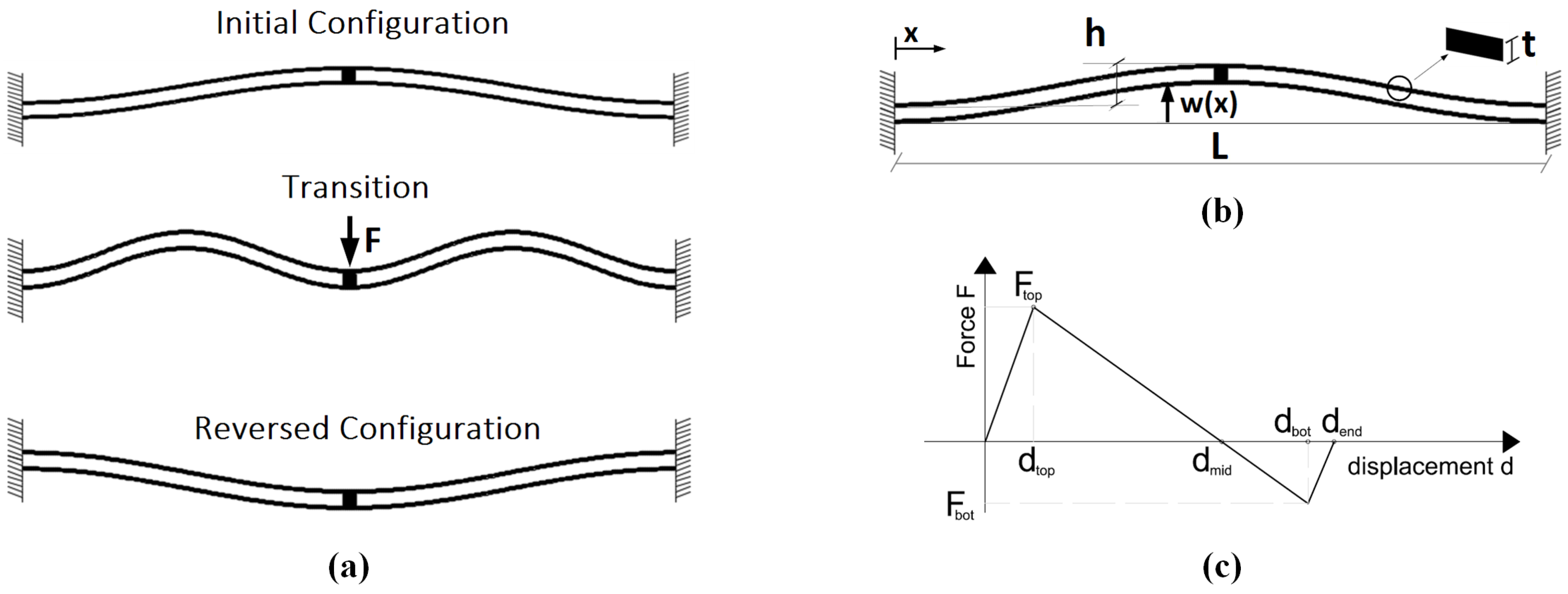
The investigated bistable mechanism, also referred to as STB mechanism, consists of two doubly-clamped curved beams clamped to each other at mid-span, as shown in Figure 1. With reference to Figure 1b, each curved beam has an as-fabricated shape which can be expressed by means of the following equation:
w ( x ) = h 2 1 cos 2 π x L
where w ( x ) is, for each curved beam, the distance of the beam from the straight line connecting its two clamped ends, h is the initial rise of the curved beams, namely h = w ( L / 2 ) , and L is the span length.
The STB mechanism is characterized by two configurations of stable equilibrium: the initial undeformed one and the reversed configuration. Indicating with Q = h / t the ratio of the initial rise to the thickness of the single curved beam, it can be analytically demonstrated that bistability is ensured as long as Q > 2.31 and the curved beams are clamped at mid-span in order to by-pass the asymmetrical buckling mode. As the STB mechanism is subjected to a force F applied at mid-span, the nonlinear static behavior of the device is characterized by a nonlinear force–displacement curve (with F changing its sign if STB occurs). During the transition from one state to the other, w ¯ ( x ) indicates the deformed shape of the mechanism and the displacement d can be defined as the difference d = w ( L / 2 ) w ¯ ( L / 2 ) . The force–displacement curve, for Q > 6, can be represented as shown in Figure 1c and the following analytical expressions hold, as reported in [34,35]:
F top 1480 E I h L 3
F bot 740 E I h L 3
F top is the force threshold value triggering the STB from the initial configuration to the reversed one and F bot is the force value triggering the STB in the opposite sense, I = b t 3 / 12 is the moment of inertia of the single curved beam, E is the Young’s modulus of the material, and b is the width of the beam.
The STB mechanism of the typology described in this section is employed for the FuC of a bimorph piezoelectric cantilever beam. The designed and manufactured prototypes are described in the following section.

3. Design of the STB-EH Device

The proposed device consists of two components: a double-beam bistable structure, switching between the initial stable configuration and the reversed one, and vice versa, and a commercial bimorph piezoelectric cantilever beam, in the following simply referred to as bimorph beam, connected to the mechanism at the mid-span. In order to reduce the resonant frequency of the piezoelectric cantilever beam and increase the overall mass, a tip mass is placed at its free end.
The bimorph beam used as energy harvester works predominantly in {3-1} mode: bending oscillations of the beam induce axial strains, in both the piezoelectric layers and of opposite sign in each of them, in the direction of the longitudinal axis and generate an electric voltage output across the electrodes, whose sign depends on the direction of polarization of the two piezoelectric layers. As the bistable mechanism snaps between its two stable states, the attached bimorph beam undergoes an acceleration which lets it oscillate in the free vibration regime characterized by a broad frequency spectrum, regardless of the excitation frequency, increasing the beam oscillations and thus the electrical output.
The bistable mechanism is manufactured using an FR4 (flame retardant) substrate with thickness 1.6 mm by means of a milling cutter (LPKF ProtoMat C30). The FR4 substrate is a glass-reinforced epoxy laminated material generally used as an electric insulator. A preliminary experimental assessment of the mechanical properties of the adopted FR4 substrate was carried out by means of three-point-bending tests, obtaining values of the Young’s modulus of FR4 ranging between 10 GPa and 22 GPa, depending on the orientation of the fibers. The design follows the analytical expressions reported in the previous section and is refined by a series of numerical simulations. The simulations have been supported by preliminary experimental tests using different prototypes aimed to explore the influence of the thickness t and initial rise h of the curved beams. The final design is a trade-off between the structural robustness of the device and the achievable elastic flexural stiffness and hence elastic energy to avoid the failure of the clamped bimorph beam during the snap.
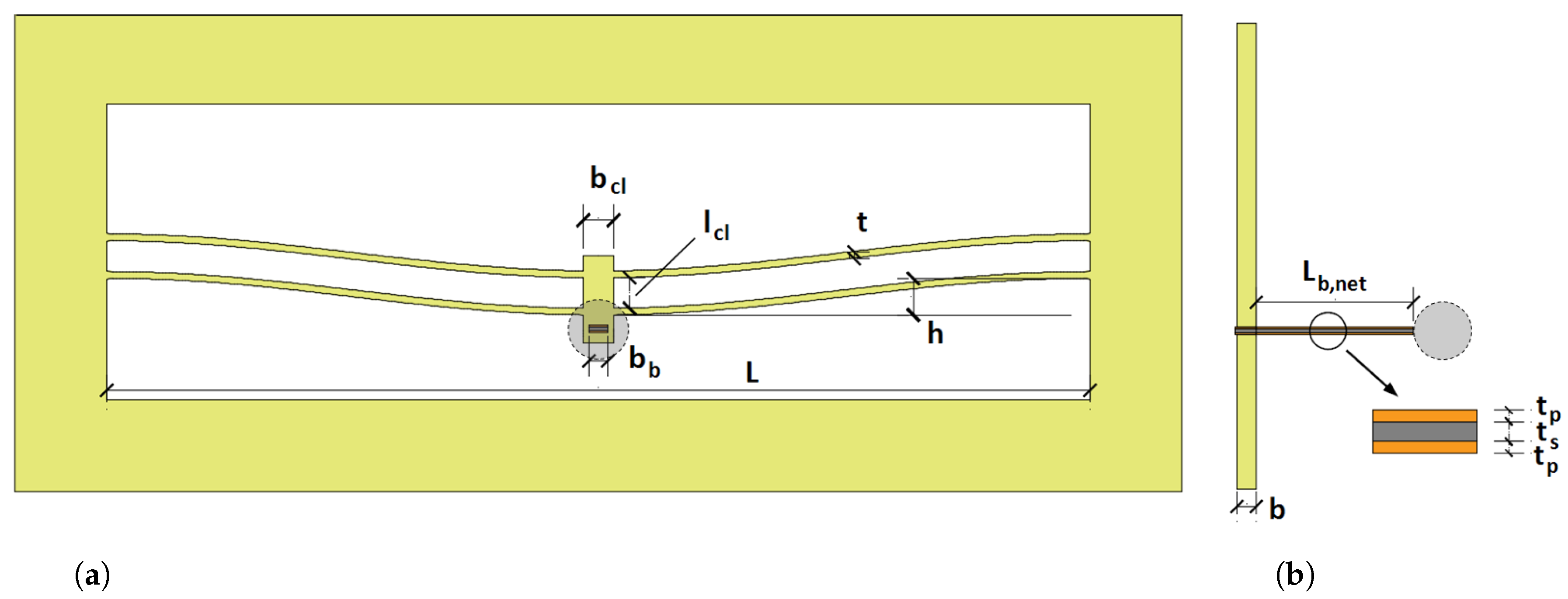
Figure 2 shows a schematic representation of the designed prototype. The bimorph piezoelectric beam is glued and clamped to the central block of the bistable mechanism, which is is manufactured with a hole in the central block with the same dimensions of the cross-section of the bimorph beam. Two different layouts are considered. Model A is composed of the bistable mechanism and the piezoelectric beam, without the tip mass. This setup is then slightly modified and model B is obtained, by placing a lead spherical mass (having radius 2.5 mm and hence mass approximately ugual to 740 mg) on the free end of the bimorph beam in order to lower its resonant frequency and increase its bending oscillations. The spherical tip mass is visible in Figure 2, with a dashed boundary.
The bimorph beam, schematically shown in Figure 3a, has dimensions L = 15 mm × w = 1.5 mm × t = 0.62 mm and consists of three main layers: a titanium shim of thickness t s sandwiched between two piezoelectric layers of thickness t p , which are oppositely poled. Each piezoelectric layer is represented in Figure 3b, which shows the equivalent electric circuit of the series connection of the piezoelectric layers, by a current source i p and a parallel-connected capacitor C p . The electrical capacitance C p and the electromechanical coupling factor are equal to 1.5 nF and 60, respectively.
The bistable mechanism has the nominal dimensions listed in Table 1a, whilst the geometrical parameters of the bimorph beam are listed in Table 1b.

4. Results

4.1. Finite Element Analyses and Numerical Results of the STB-EH Device in Open-Circuit Configuration

The proposed device is modeled using the software ABAQUS for finite element analysis (FEA), in which it is possible to account for the electromechanical coupling and the nonlinearity of the bistable mechanism. A single deformable solid part is considered in the tridimensional modeling space and the various components are extruded from bidimensional shape. A linear elastic constitutive law is assumed for the different components, the values of Young’s modulus are E FR 4 = 14 GPa , E p = 60 GPa and E t = 115 GPa for FR4, titanium and PZT, respectively; Poisson’s ratio ν FR 4 = 0.16 , ν p = 0.33 and ν t = 0.30 ; mass density ρ FR 4 = 1560 kg / m 3 , ρ p = 7500 kg / m 3 and ρ t = 11,340 kg/m3. For the sake of simplicity, an equivalent isotropic model is adopted for FR4, in view of the fact that the curved beams are thin elements almost aligned with the material direction characterized by the abovementioned uniaxial stiffness. The restraint conditions applied to the model are of perfect clamps in correspondence with the four ends of the curved beams of the bistable mechanism. The model are meshed by means of quadratic hexaedral finite elements; in particular, those employed to model the piezoelectric layers belong to the piezoelectric family, whilst the remainder of the device is modeled with 3D stress elements.
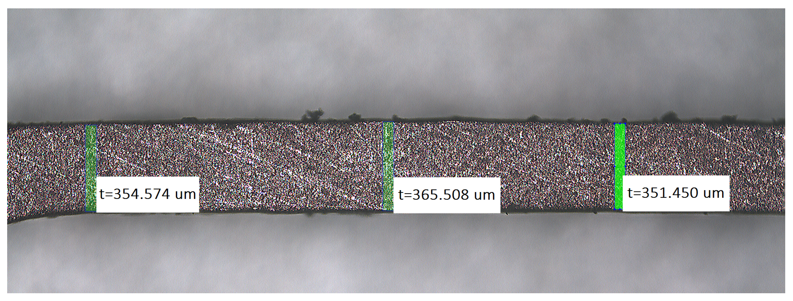
In order to model the bistable mechanism, it is necessary to preliminarily measure the thickness of the curved beams. Forty thickness measurements are made by means of an optical microscope along each of the four curved portions, as shown in Figure 4. The measurements show how significantly the thickness varies along the length of the single curved beam: for instance, for the lower right-end beam, the maximum measured value is 384.23 μ m whilst the minimum measured value is 345.21 μ m. The mean values and coefficient of variations (CoV) are (refer to Figure 2): top left beam 352.88 μ m (CoV 2.38%); bottom left beam 365.94 μ m (CoV 2.65%); top right beam 365.44 μ m (CoV 2.49%); bottom right beam 351.02 μ m (CoV 2.49%). In all the cases, the real thickness is lower than the nominal thickness of about 550 μ m. The asymmetry arising from the thickness variation caused by the tolerances of the fabrication process is modeled in the FEA simulation tool by assigning to the four curved element, for the sake of simplicity, the abovementioned mean value of thickness, uniform along each curved beam but varying from one beam to the other. The asymmetric nature of the bistable mechanism affects its expected bistable behavior, resulting in a rotation of the central clamp when a transition from the initial to the reversed state is triggered, as shown in Figure 5. Similar results have been obtained with the execution of different analyses, e.g., by introducing some local variation in the thickness of each beam, according to the measurements.
Consequently, the second non-symmetrical buckling mode is not completely prevented, which is detrimental for the bistability. On the other hand, bistability depends also on the ratio Q = h / t : while the thickness varies randomly along the length of the bistable mechanism, the average thickness has a lower value than the expected nominal value, with an ensuing increase of Q and thus of bistability. Hence, the rotational motion of the bistable mechanism caused by the imperfections and the ensuing reduction of bistability are partially compensated by the increase of Q.
From the static nonlinear analysis under displacement control, the force–displacement and strain energy ( E )-displacement curves are obtained, as shown in Figure 6. The static analysis is performed via arc-length control accounting for geometrical nonlinearities. The analysis consists of applying a displacement along the y-axis at the mid-span of the bistable mechanism, in correspondence with the central block, with a variation in the range 0 < d < d end , where d end 2 h . The reaction force is computed and the nonlinear curve is obtained. The bistable behavior of the mechanism is evidenced from the force–displacement curve: the latter, starting from the undeformed configuration and initially linear, becomes nonlinear as the stiffness of the bistable mechanism decreases. The STB force threshold F top is hence reached, the stiffness becomes negative and the reaction force decays until becoming null in correspondence with the unstable configuration for d = d mid = 4.23 mm. As the force becomes negative, equilibrium is allowed only with a force of reversed sign: the point of minimum F bot is hence reached and corresponds to the the value of force which triggeres STB from the reversed to the initial configuration. The final point of the curve d end indicates the reversed stable configuration.
The E -displacement curve is obtained from the same static nonlinear analysis as the sum of the strain energy of each finite element of the model. The curve is characterized by two points of local minimum, corresponding to the stable configurations, and a point of local maximum, corresponding to the transitional unstable configuration. As expected, the reversed configuration is less stable than the initial one, since the energy well corresponding to the reversed state (namely, the difference Δ E reversed = E mid E end = 1414.4   μ J 1216.6   μ J = 197.8   μ J ) is significantly more shallow than the one relative to the undeformed configuration ( Δ E undeformed = E mid E d = 0 = 1414.4   μ J ). This aspect can be explained in terms of forces: a lower magnitude of force is necessary to bring the mechanism from its reversed configuration to the initial one than vice versa. As a matter of fact, the values of forces obtained from the static analysis are F top = 630 mN and F bot = 220 mN , respectively. It is worth noting that the theoretical predictions, given by Equations (2) and (3), are different with respect to the numerical outcomes. As a matter of fact, the formulas are referred to the perfect case, with equal thickness for all the beams. Taking into account the overall average thickness, i.e., 358.82 μ m, and an equivalent Young’s modulus equal to 14 GPa for FR4, one finds F top an = 748 mN and F bot an = 374 mN . The reduction of limit loads is a consequence of the sensitivity to imperfection of the considered structure [36]: the asymmetry of beams’ thickness that characterizes the FE model entails a premature snap with respect to the theoretical framework.
For model A, the total mass, sum of the mass of the bimorph beam, and the mass of the bistable mechanism is m tot , A 340 mg and thus the value of input acceleration triggering STB, respectively, from the initial to the reversed state and vice versa are a top , A = F top / m tot , A = 189   g and | a bot , A | = | F bot | / m tot , A = 66   g . Vibrational piezoelectric energy harvesters are generally employed to scavenge energy from ambient vibrations, characterized by accelerations acting at low frequencies and magnitude. It is possible to decrease the magnitude of the acceleration necessary for STB by simply increasing the mass of the device: as a matter of fact, for model B, the total mass is m tot , B = m tot , A + m tip 1100 mg . Given the increase of mass, in the simplifying hypothesis of invariance of snap loads for the models, a proportional reduction of the acceleration is expected. Furthermore, an increase of mass can be useful if the EH device has to scavenge energy under the effect of impacts or, in case the increase of mass is sufficiently high, if the device is tilted.
In addition to the static analysis, a modal analysis is carried out, by means of a frequency—linear perturbation analysis around the initial configuration of the bistable mechanism. The Lanczos eigenvalue solver is adopted and the obtained modal frequencies are listed in Table 2 for model A and in Table 3 for model B. Clearly, in the second case, the modal frequencies are relevantly lower due to the presence of the lead tip mass on the free end of the bimorph beam. The examination of the first mode shape indicates a significant out-of-plane motion of the bistable mechanism, together with the oscillation of the cantilever beam.
Subsequently, a dynamic implicit analysis accounting for geometrical nonlinearities and the electro-mechanical coupling is performed. In the FE model, the electromechanical coupling is accounted for by means of the piezoelectric coefficient d 31 = 242 × 10 12 C / N . In addition, the following electrical boundary conditions are imposed: the bottom surface of the lower piezoelectric layer (lower electrode) is set to zero voltage, whereas the voltage on the top surface of the upper layer (upper electrode) is let free to vary in time but is set constant over the whole surface. The damping is introduced via the Rayleigh model, tuned in order to have an arbitrarily chosen damping ratio ξ = 0.005 for the first eigenmode.
The test is here described with the help of the force–displacement curve shown in Figure 6a. First, it is possible to verify that the structure does not show an abrupt transition from the initial to the reversed configuration. Then, the snap in the opposite sense is exploited. To that purpose, in the first phase, the bistable mechanism is brought to its reversed stable configuration ( d d end ). From this configuration, in the second phase, an opposite displacement is applied at mid-span beyond the point of inversion of the force sign ( d < d mid ), so that the bistable mechanism, in the third stage, automatically and impulsively snaps back to its initial configuration. On the FE model, the first two phases are modeled by means of nonlinear static analyses with assigned displacement. As d < d mid , the displacement restraint is released and a dynamic implicit analysis starts, with the mechanism switching back to its initial configuration, inducing oscillations of the bimorph beam. The dynamic step runs over 200 ms, with a time increment equal to 0.1 ms.
The numerical outcomes of the dynamic analyses are shown in the next section, along with the experimental counterparts. It can be observed that the response is dominated by the first two modal frequencies, which involve a combined motion of the bistable mechanism and of the bimorph beam.

4.2. Experimental Characterization of the STB-EH Prototypes in Open-Circuit Configuration

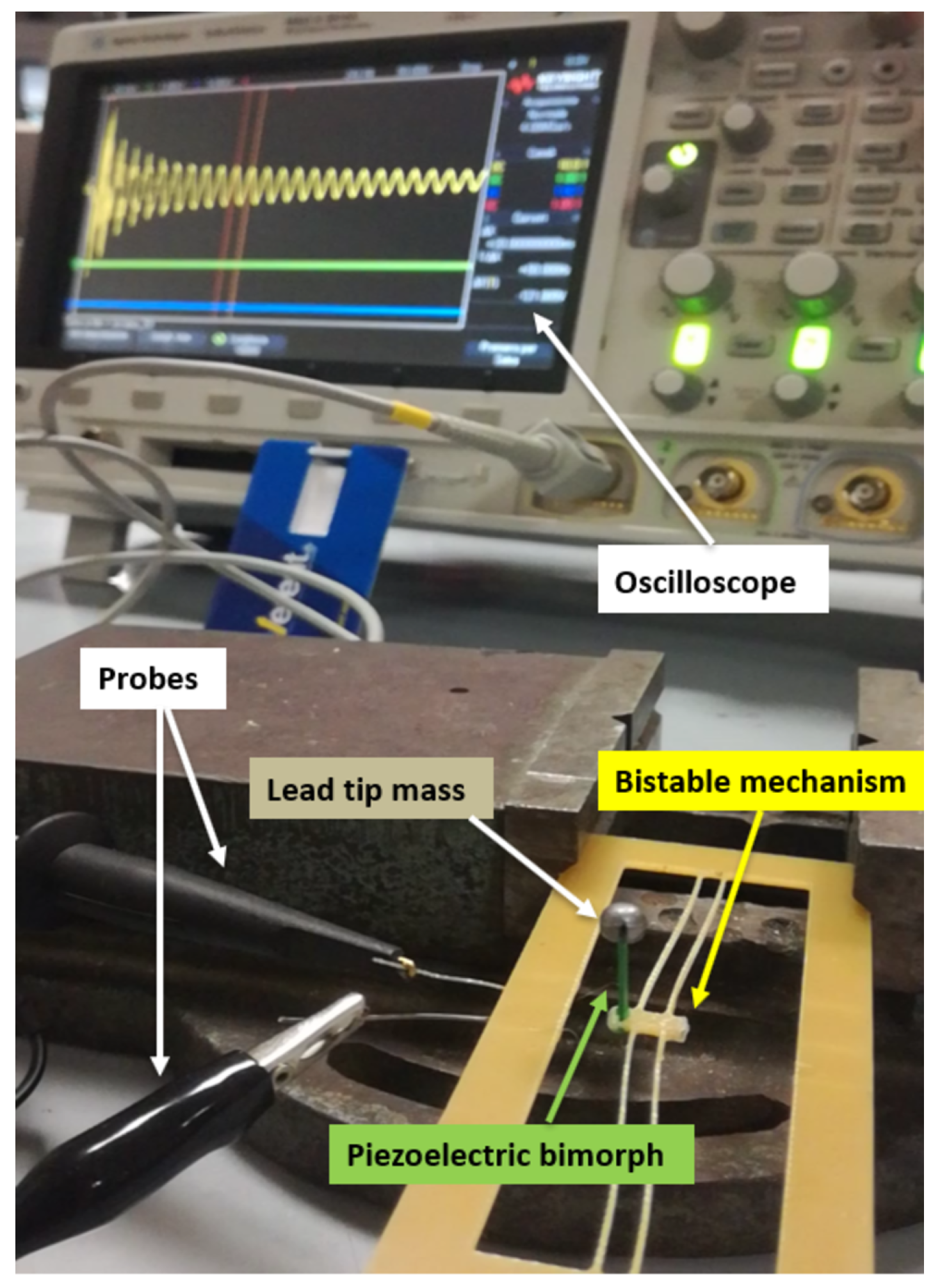
Figure 7 shows the experimental setup adopted to characterize the STB-EH prototypes (specifically, model B is shown in the figure, but the same setup is used also for the other tests). Voltage is measured by means of probes connected to an oscilloscope and to the electrodes of the bimorph beam.
Firstly, the resonant frequencies of the bimorph beams for models A and B are estimated by measuring the open-circuit voltage subsequent to a mechanical impulse. To this purpose, the device is clamped in a vice with the exception of the bimorph beam which is let free to oscillate due to an imparted mechanical impulse to the vice. Figure 8 and Figure 9 show the Fourier transform of four repeated measurements of the open-circuit output voltage of the piezoelectric cantilever beam of models A and B, respectively.
The peaks in the spectra correspond to the resonant frequencies of the piezoelectric cantilever beams, f res , 1 exp = 1850 Hz and f res , 2 exp = 305 Hz for models A and B, respectively. The analytical values of the resonant frequencies, computed according to the well-known formula valid for cantilever beams, are f res , 1 analyt = 2056 Hz and f res , 2 analyt = 325 Hz for models A and B, respectively. The overestimate of the analytical values is attributed to the fact that the bimorph beam is not perfectly clamped and that the actual mechanical and geometrical parameters of the beam may slightly differ from the ones employed for the computation.
Subsequently, the numerical analyses described in Section 4.1 are verified by different series of tests. In particular, the open-circuit output voltage arising from the oscillations induced by STB, which is triggered by manually displacing the bistable mechanism from the reversed to the initial undeformed configuration, is measured. Figure 10a and Figure 11a show the measured open-circuit output voltage obtained with the model A and model B, respectively.
The Fourier transform of four repeatead measurements for model A and model B are shown in Figure 10b and Figure 11b, respectively. The curves are characterized by two peaks for both models, which correspond to the two first global modes, namely those involving the motion of both the bistable mechanism and the bimorph beam. Figure 10 and Figure 11 also show the comparisons between the numerical and experimental results. In particular, a satisfactory agremeent is obtained, both in terms of frequency and magnitude.
With reference to model A, the resonant frequency ( f res , 1 = 1850 Hz ) of the bimorph beam is higher than the two global modal frequencies and is hence far from being directly excited. Conversely, for model B, the resonant frequency ( f res , 2 = 305 Hz ) of the bimorph beam and the global frequencies are closer to one another, and consequently the induced oscillations and output voltage have higher amplitude.
The results shown in Figure 10 and Figure 11 refer to tests in which STB occurs from the reversed to the initial undeformed stable configurations. As explained by means of the numerical analyses, the curved beams of the bistable mechanism do not snap dynamically from the initial undeformed configuration to the reversed one and, in this situation, FuC does not occurr. The Fourier transform shown in Figure 11b is characterized, in comparison with the one shown in Figure 10b, by peaks at lower frequencies and higher values of voltage. These aspects are both due to the increase of mass caused by the presence of the lead sphere on the bimorph’s free edge in model B, which causes the reduction of the global modal frequencies and the increase of the compliance of the beam.

4.3. Experimental Characterization of the STB-EH Prototype Connected to a Resistive Load and to a Rectifier Circuit with Storage Capacitor

The tests described in the previous section aim at the characterization of the STB-EH prototype in the open-circuit situation, considering the manual activation of the bistable mechanism. An additional set of experiments is devoted to the investigation of the performances in the presence of an electrical load. As before, the bistable mechanism snaps from the reversed configuration to the inital undeformed one; two kinds of external circuits are considered, namely: a resistive load and a full-wave bridge rectifier circuit connected to a storage capacitor.
Model B is considered, since the experimental tests, reported in Section 4.2, confirm that it is the most promising configuration. The STB-EH prototype is characterized connecting a resistive load R L to the bimorph beam. The voltage across the resistance is measured after snap occurs, and the extracted power is computed according to the Joule’s law. Several experiments are executed with different attached resistances, in order to find the optimal value of R L that gives the maximum value of the instantaneous power. Figure 12 shows that the instantaneous power has a maximum value of 4 mW for R L = 400   k Ω , which represents the optimal value for the free vibration of the STB-EH prototype after the snap. In this situation, the average power is computed as follows:
P mean = V rms 2 R L = 91.84   μ W
The corresponding energy, evaluated over a period of 190 ms, is 17.48 μ J . For the sake of comparison, the energy barrier to activate the snap from the reversed to the initial configuration can be measured in Figure 6 and it is equal to 197.76 μ J . Therefore, the harvested energy for a single snap is about 8.84% of the energy that is needed to activate the snap. The average power can be used to compute the power density, with respect to the volume of the active material. On an account taken of the geometric features summarized in Table 1b, one finds that the power density is 9.11 mW/cm 3 . Such a value is in agreement with the data reported in [37], where the median power density, over a set of 29 harvesters proposed in the literature, is 5.4 mW/cm 3 .
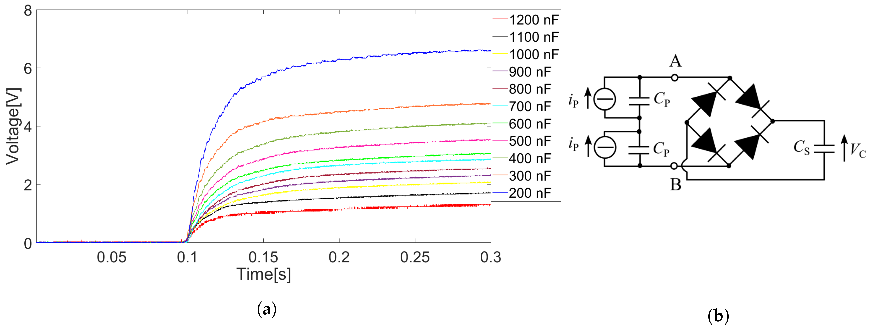
Subsequently, the output of the bimorph beam is connected to a circuit composed of a full-wave bridge rectifier and a storage capacitor, with capacitance C S . For the rectifier, p-n diodes 1N4148 have been used. The energy W stored in the capacitor is computed as:
W = 1 2 C S V C 2
Figure 13a shows the voltage across the capacitor measured after triggering the snap from the reversed configuration to the initial undeformed one for different values of the capacitance. After the snap, the voltage exponentially increases, and the lower the value of capacitance, the lower the time constant, and the higher the voltage, as expected. Figure 14 shows the values of voltage and stored energy measured 0.2 s after the snap for each capacitance value. The maximum stored energy, 4.5 μ J , is about 2.28% of the mechanical energy that is needed to activate the snap.

4.4. Experimental Characterization of the STB-EH under Sinusoidal Excitation

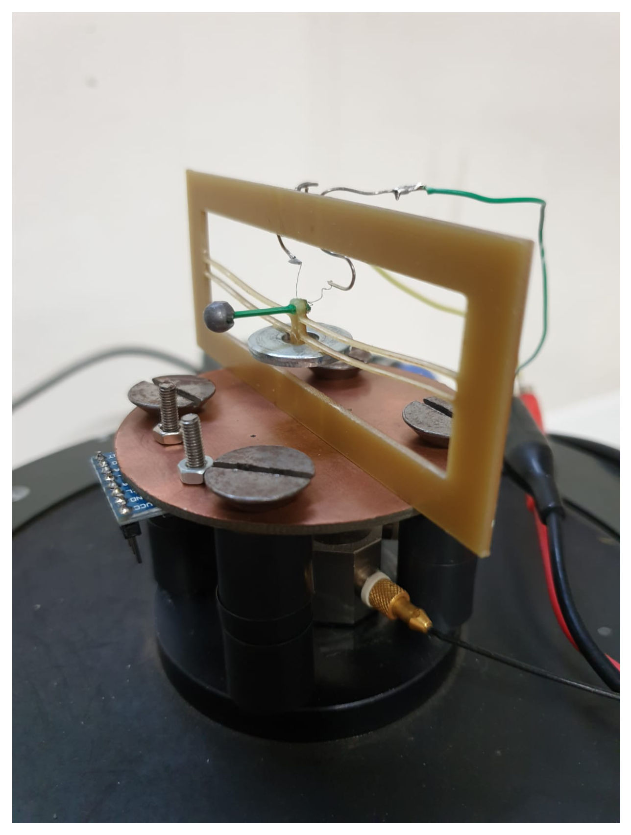
Finally, to explore the response in case of an external acceleration history, the prototype is tested on an electrodynamic shaker (Bruel and Kjaer Vibration Exciter 4808). The acceleration necessary for the STB from the reversed to the initial configuration is excessive for the shaker capability, since, for model B, it exceeds 20 g. To carry out the experimental test, it is possible to introduce a modification of the prototypes to increase the overall mass without affecting the dynamic response of the cantilever. Consequently, a metal washer, with mass equal to 3.8 g, is added in a symmetric fashion on the central block of the bistable mechanism: the final experimental configuration is shown in Figure 15. Focus is again restricted on model B, modified with the addition of the washer. The additional mass does not alter the vibration of the piezoelectric cantilever; moreover, it does not affect significantly the first eigenmode. The mass is increased in order to reduce the acceleration necessary for the STB from the reversed to the initial configuration. On the other hand, the introduction of the washer is detrimental for the performance of the STB mechanism, since a part of the released elastic energy is converted into kinetic energy of the mass which do not participate in the motion of the piezoelectric cantilever. As a consequence, performances are expected to be lower than reported in Figure 11.
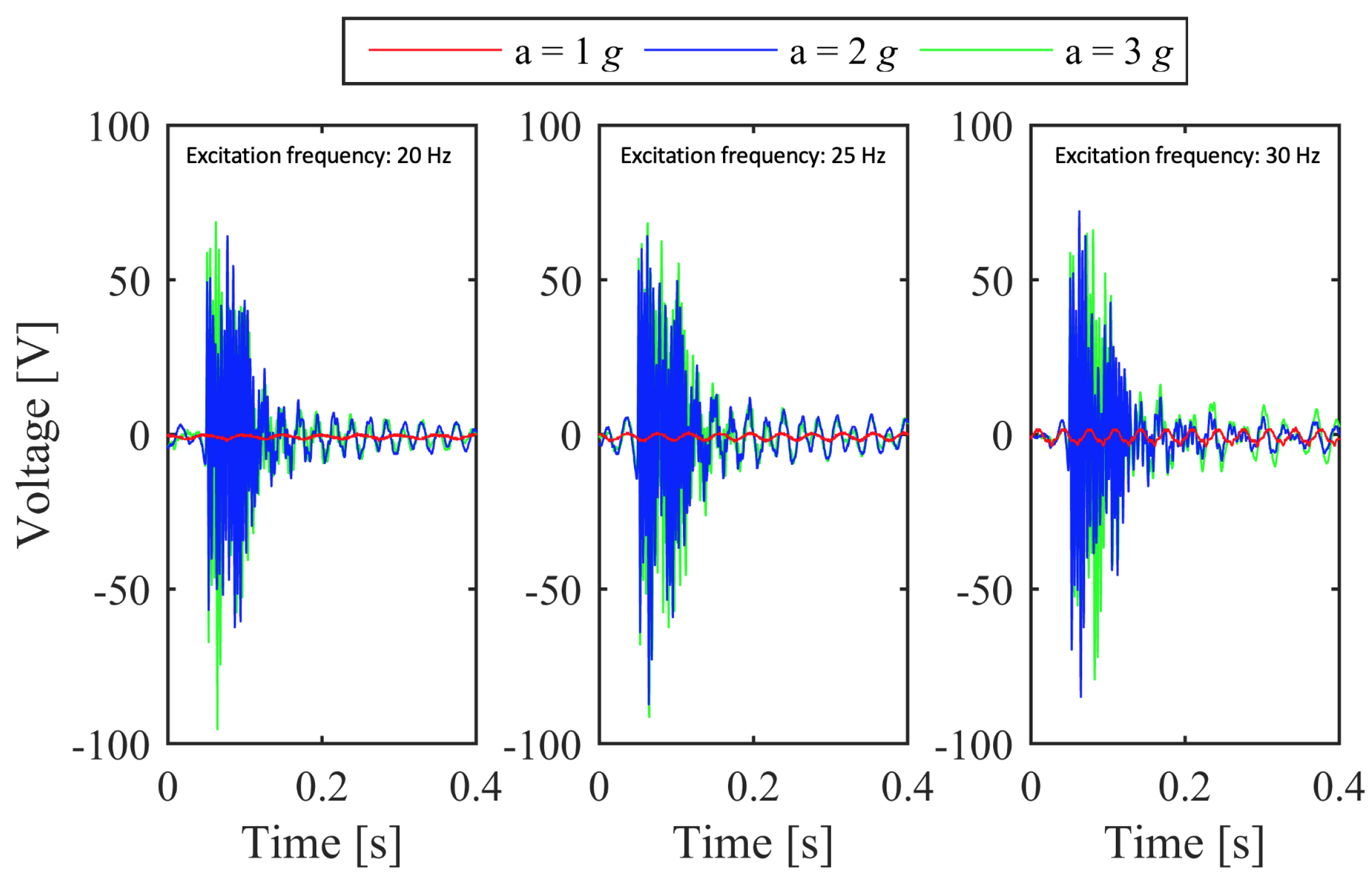
The prototype is pre-deformed so that the reversed configuration is achieved. Subsequently, the structure is excited with different time histories of acceleration, changing the frequency, the amplitude, and the shape of the signal. In the case of sinusoidal acceleration at frequencies well below the first eigenmode of the device, as long as the peak amplitude is lower than 2 g, STB does not happen and the measured voltage is negligible. The peak amplitude of 2 g is sufficient to pass over the energy barrier of the bistable mechanism and to trigger the FuC. This value of acceleration is lower than expected: such a difference can be explained in view of the uncertainties in the constitutive law of FR4 and the relevant properties. Nonetheless, the low-frequency, low-amplitude applied acceleration history is enough to trigger the STB of the bistable mechanism from its reversed configuration to the initial undeformed one. Hence, the bistable mechanism is less stable in its reversed configuration than assessed numerically, namely it is characterized by a lower absolute value of F bot than the one indicated in Figure 6.
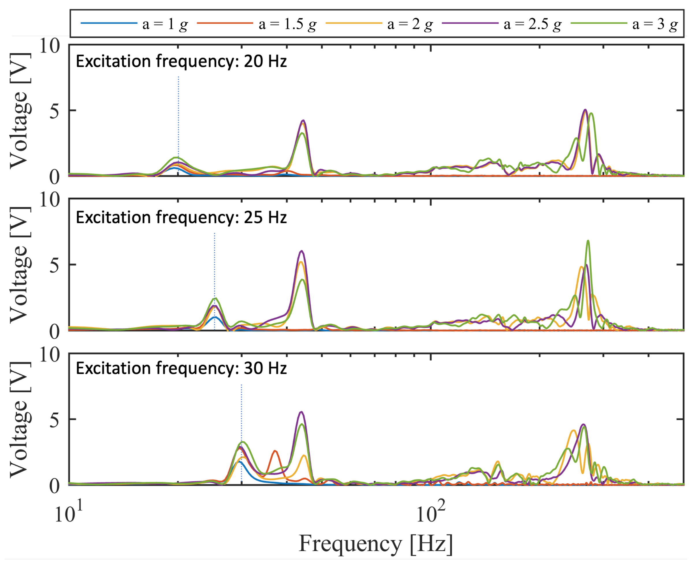
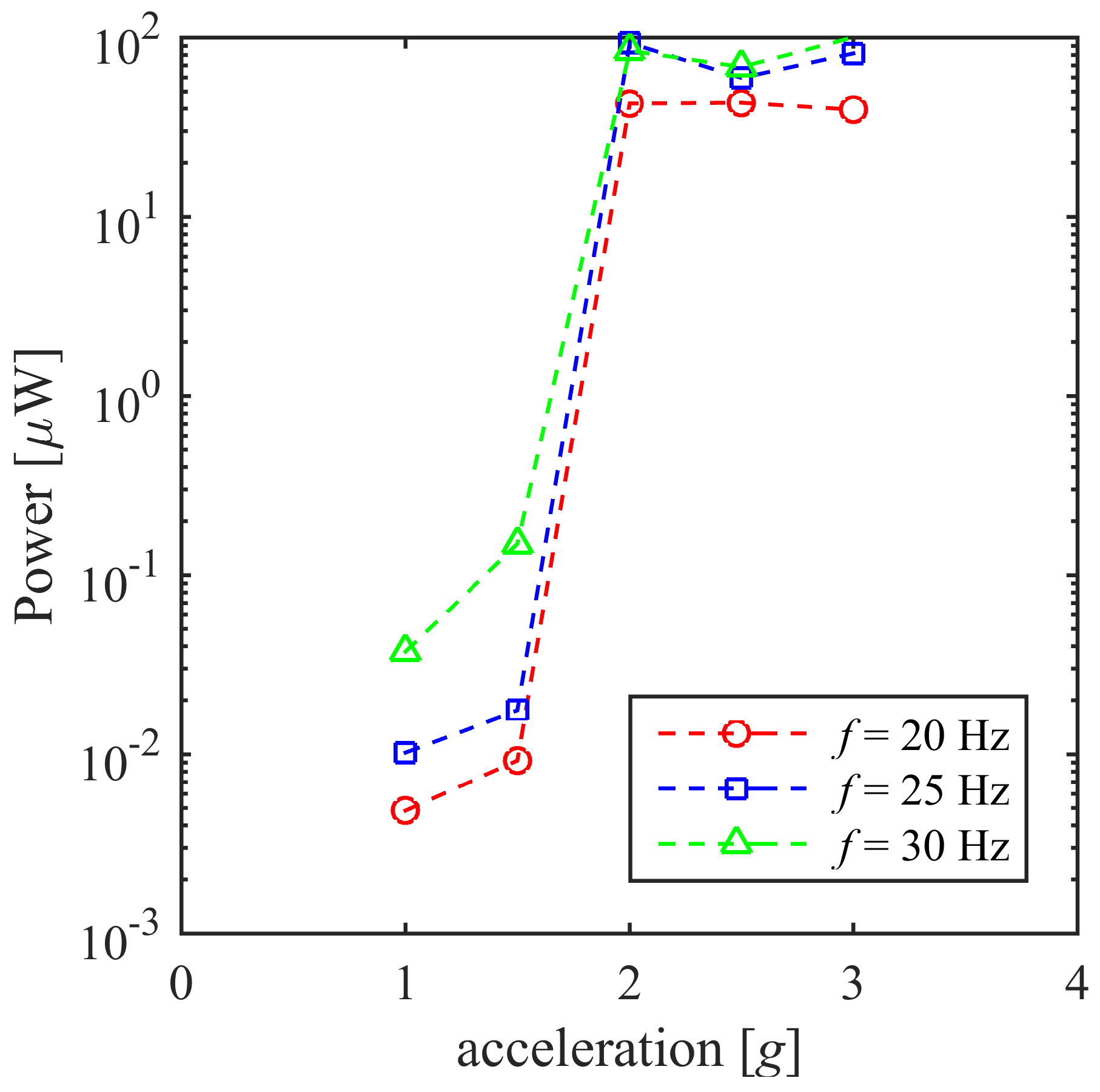
Figure 16 shows the open-circuit voltage, for sinusoidal accelerations with frequency 20 Hz, 25 Hz and 30 Hz, with different peak amplitude, namely 1 g, 2 g, and 3 g. When the peak acceleration is larger than or equal to 2 g, FuC is triggered and the open-circuit voltage attains peaks that are comparable with the case of Figure 11, where STB is provoked manually. The achieved results confirm that, if the input signal is able to pass over the energy barrier of the second stable configuration, the occurence of STB adds high frequency components in the frequency spectrum of the output signal, in spite of the low-frequency input excitation, as shown in Figure 17. The output voltage is distributed over a frequency band that is broader than the previous cases. Other tests are carried out, by attaching the piezoelectric material to a resistive load R L = 400   k Ω , so that the extracted power can be computed on the basis of the recorded voltage and of Equation (4). Figure 18 shows the average power that is obtained for different frequencies and peak accelerations. The results confirm that, for peak acceleration lower than 2 g, the average power is neglibible, since STB does not occur. When the peak acceleration attains the STB threshold, the average power attains values similar to the case shown in Section 4.3. Peak accelerations larger than 2 g are considered as well: since the energy barrier is passed for 2 g, the same happens, a fortiori, for accelerations beyond that threshold and the extracted power does not change significantly.
5. Discussion and Conclusions

On the basis of the results obtained from the experimental tests and the numerical simulations, the effectiveness of FuC due to STB of the designed device is demonstrated.
As a matter of fact, when the bistable mechanism is subject to a displacement and let free to impulsively snap from the reversed to the initial state, the measured output voltage of the converter contains a wide range of high frequency components. The employment of a tip mass, while reducing the resonance frequency of the bimorph beam, implies a significant increase in terms of voltage output, due to the increased deformation of the beam, leading to higher strains in the piezoelectric layers. The results obtained from the experimental tests are compared with those coming from a FE model accounting for geometrical nonlinearities and for the electromechanical coupling, showing a good agreement.
The importance of STB when trying to harvest energy from low-frequency input excitation is demonstrated when testing the EH device on the shaker: as the device is subject to a low-frequency excitation having peak amplitude above the STB threshold, the bistable mechanism switches between a stable configuration (the reversed one) to the opposite one (the initial configuration) and the frequency response spectrum contains high-frequency components, regardless of the frequency of the input excitation. A peak voltage of almost 60 V is obtained from the STB test on the shaker with an input acceleration of 2, or larger than such a threshold, acting at different frequencies, well below the resonant frequency of the device. The tests are executed in the presence of an additional mass, with the purpose of reducing the acceleration needed to induce the snap.
Moreover, it has been experimentally demonstrated that the EH device is able to generate an electrical output when connected to an external circuit: a peak power of around 4 mW has been generated using a resistive load of 400 k Ω and a maximum energy of about 4.5 μ J is stored in 0.2 s on a 200 n F capacitor. The average power, confirmed also by means of the tests on the shaker, is around 100 μ W .
The obtained results represent a sound basis for further developments in the field of bistable devices for FuC. The prototype could be modified by reducing the dimensions of the bistable mechanism, for instance using different materials and manufacturing methods for its realization. The use of a more sophisticated production process may reduce the geometrical imperfections that have been proved (numerically and experimentally) to affect the bistable behavior. A refined design of the structural shape should be aimed at the improvement of some specific aspects. As an example, it would be desirable to reduce the difference between the two energy wells that characterize the bistable behavior: such an objective could be attained by carrying out extensive parametric analyses or shape optimization. The expected result is a bidirectional use of the device, exploiting the abrupt snap both from the original to the reversed configuration and vice versa. In that way, it would be possible to circumvent the limitation of the present study, namely the fact that STB happens only from the second stable configuration back to the undeformed one. Another direction for improvement is represented by the operation of the device under external excitation with lower amplitude, closer to those characterizing ambient vibrations: the increase of mass is a possible solution, with some drawbacks that can be circumvented through the optimization of the geometric features. In that way, EH could be attractive for the typical situation of low-amplitude ambient vibration characterized by a wide band in the low-frequency range.

Author Contributions

Conception and design of the device, All the Authors; Computational analyses, A.S., R.A., and A.A.F.; Manufacturing of specimens and execution of experimental tests, A.S., M.F., and M.B.; Analysis of the results, All the Authors; Original draft preparation, A.S.; Writing—Editing, R.A., M.B., and M.F.; Supervising, V.F. and A.A.F. All authors have read and agreed to the published version of the manuscript.

Funding

This research received no external funding.

Acknowledgments

Alberto Tiburzi, from the Department of Information Engineering of the University of Brescia, for the support in the manufacturing of the prototype; Maria Santangelo, Materials Testing Laboratory (LPM) of Politecnico di Milano, for the support in the tests of the FR4 specimens.

Conflicts of Interest

The authors declare no conflict of interest.

References

  1. Demori, M.; Ferrari, M.; Bonzanini, A.; Poesio, P.; Ferrari, V. Autonomous Sensors Powered by Energy Harvesting by von Karman Vortices in Airflow. Sensors 2017, 17, 2100. [Google Scholar] [CrossRef] [PubMed] [Green Version]
  2. Cellini, F.; Cha, Y.; Porfiri, M. Energy harvesting from fluid-induced buckling of ionic polymer metal composites. J. Intell. Mater. Syst. Struct. 2014, 25, 1496–1510. [Google Scholar] [CrossRef]
  3. Cha, Y.; Kim, H.; Porfiri, M. Energy harvesting from underwater base excitation of a piezoelectric composite beam. Smart Mater. Struct. 2013, 22, 115026. [Google Scholar] [CrossRef]
  4. Roundy, S.; Wright, P.K.; Rabaey, J.M. A Study of Low Level Vibrations as a Power Source for Wireless Sensor Nodes. Comput. Commun. 2003, 26, 1131–1144. [Google Scholar] [CrossRef]
  5. Williams, C.B.; Yates, R.B. Analysis of a micro-electric generator for microsystems. Sensors Actuators A Phys. 1996, 52, 8–11. [Google Scholar] [CrossRef]
  6. duToit, N.E.; Wardle, B.; Kim, S.-G. Design considerations for MEMS-scale piezoelectric mechanical vibration energy harvesters. Integr. Ferroelectr. 2005, 71, 121–160. [Google Scholar] [CrossRef]
  7. Kim, H.S.; Kim, J.-H.; Kim, J. A review of piezoelectric energy harvesting based on vibration. Int. J. Precis. Eng. Manuf. 2011, 12, 1129–1141. [Google Scholar] [CrossRef]
  8. Miso, K.; Dugundji, J.; Wardle, B. Efficiency of piezoelectric mechanical vibration energy harvesting. Smart Mater. Struct. 2015, 24, 055006. [Google Scholar]
  9. Bai, Y.; Tofel, P.; Hadas, Z.; Smilek, J.; Losak, P.; Skarvada, P.; Macku, R. Investigation of a cantilever structured piezoelectric energy harvester used for wearable devices with random vibration input. Mech. Syst. Signal Process. 2018, 106, 303–318. [Google Scholar] [CrossRef] [Green Version]
  10. Baù, M.; Ferrari, M.; Tonoli, E.; Ferrari, V. Sensors and energy harvesters based on piezoelectric thick films. Procedia Eng. 2011, 25, 737–744. [Google Scholar] [CrossRef] [Green Version]
  11. Ferrari, M.; Ferrari, V.; Guizzetti, M.; Marioli, D. Piezoelectric low-curing-temperature ink for sensors and power harvesting. Lect. Notes Electr. Eng. 2010, 54, 77–81. [Google Scholar]
  12. Ardito, R.; Corigliano, A.; Gafforelli, G.; Valzasina, C.; Procopio, F.; Zafalon, R. Advanced Model for Fast Assessment of Piezoelectric Micro Energy Harvesters. Front. Mater. 2016, 3, 17. [Google Scholar] [CrossRef] [Green Version]
  13. Gafforelli, G.; Ardito, R.; Corigliano, A.; Valzasina, C.; Procopio, F. Numerical simulations of piezoelectric MEMS energy harvesters. In Proceedings of the 15th International Conference on Thermal, Mechanical and Mulit-Physics Simulation and Experiments in Microelectronics and Microsystems (EuroSimE), Ghent, Belgium, 7–9 April 2014; pp. 1–9. [Google Scholar]
  14. Gafforelli, G.; Ardito, R.; Corigliano, A. Improved one-dimensional model of piezoelectric laminates for energy harvesters including three-dimensional effects. Compos. Struct. 2015, 127, 369–381. [Google Scholar] [CrossRef] [Green Version]
  15. Ardito, R.; Corigliano, A.; Gafforelli, G. A highly efficient simulation technique for piezoelectric energy harvesters. J. Phys. Conf. Ser. 2015, 660, 012141. [Google Scholar] [CrossRef] [Green Version]
  16. Challa, V.R.; Prasad, M.G.; Shi, Y.; Fisher, F.T. A vibration energy harvesting device with bidirectional resonance frequency tunability. Smart Mater. 2008, 17, 15035. [Google Scholar] [CrossRef]
  17. Barton, D.A.W.; Burrow, S.G.; Clare, L.R. Energy Harvesting from Vibrations with a Nonlinear Oscillator. In Proceedings of the ASME 2009 International Design Engineering Technical Conferences & Computers and Information in Engineering Conference, San Diego, CA, USA, 30 August–2 September 2009. [Google Scholar]
  18. Procopio, F.; Valsazina, C.; Corigliano, A.; Ardito, R.; Gafforelli, G. Piezoelectric Transducer for an Energy-harvesting System. U.S. Patent US20150035409 A1, 29 July 2014. [Google Scholar]
  19. Hajati, A.; Kim, S.-G. Ultra-wide bandwidth piezoelectric energy harvesting. Appl. Phys. Lett. 2011, 99, 083105. [Google Scholar] [CrossRef] [Green Version]
  20. Gafforelli, G.; Xu, R.; Corigliano, A.; Kim, S.-G. Modelling of a bridge-shaped nonlinear piezoelectric energy harvester. J. Phys. Conf. Ser. 2013, 476, 012100. [Google Scholar] [CrossRef] [Green Version]
  21. Gafforelli, G.; Xu, R.; Corigliano, A.; Kim, S.-G. Experimental verification of a bridge-shaped, nonlinear vibration energy harvester. Appl. Phys. Lett. 2014, 105, 203901. [Google Scholar] [CrossRef] [Green Version]
  22. Alghisi, D.; Dalola, S.; Ferrari, M.; Ferrari, V. Triaxial ball-impact piezoelectric converter for autonomous sensors exploiting energy harvesting from vibrations and human motion. Sens. Actuators A 2015, 233, 569–581. [Google Scholar] [CrossRef]
  23. Ferrari, M.; Baù, M.; Cerini, F.; Ferrari, V. Impact-enhanced multi-beam piezoelectric converter for energy harvesting in autonomous sensors. Procedia Eng. 2012, 47, 418–421. [Google Scholar] [CrossRef] [Green Version]
  24. Ferrari, M.; Alghisi, D.; Baù, M.; Ferrari, V. Nonlinear multi-frequency converter array for vibration energy harvesting in autonomous sensors. Procedia Eng. 2012, 47, 410–413. [Google Scholar] [CrossRef] [Green Version]
  25. Alghisi, D.; Ferrari, V.; Ferrari, M.; Touati, F.; Crescini, D.; Mnaouer, A.B. A new nano-power trigger circuit for battery-less power management electronics in energy harvesting systems. Sens. Actuators A 2017, 263, 305–316. [Google Scholar] [CrossRef]
  26. Alghisi, D.; Ferrari, V.; Ferrari, M.; Crescini, D.; Touati, F.; Mnaouer, A.B. Single- and multi-source battery-less power management circuits for piezoelectric energy harvesting systems. Sens. Actuators A 2017, 264, 234–246. [Google Scholar] [CrossRef]
  27. Ferrari, M.; Ferrari, V.; Guizzetti, M.; Marioli, D. Investigation on electrical output combination options in a piezoelectric multifrequency converter array for energy harvesting in autonomous sensors. In Proceedings of the 1st International Conference on Sensor Device Technologies and Applications, Venice, Italy, 18–25 July 2010; pp. 258–263, art. n. 5632176. [Google Scholar]
  28. Andò, B.; Baglio, S.; Baù, M.; Bulsara, A.R.; Ferrari, V.; Ferrari, M.; L’Episcopo, G. A nonlinear energy harvester by direct printing technology. Procedia Eng. 2012, 47, 933–936. [Google Scholar] [CrossRef] [Green Version]
  29. Cottone, F.; Gammaitoni, L.; Vocca, H.; Ferrari, M.; Ferrari, V. Piezoelectric buckled beams for random vibration energy harvesting. Smart Mater. Struct. 2012, 21, 035021. [Google Scholar] [CrossRef]
  30. Andò, B.; Baglio, S.; Bulsara, A.R.; Marletta, V.; Ferrari, V.; Ferrari, M. A Low-Cost Snap-Through-Buckling Inkjet-Printed Device for Vibrational Energy Harvesting. IEEE Sensors J. 2015, 15, 3209–3220. [Google Scholar] [CrossRef]
  31. Jung, S.-M.; Yun, K.-S. A wideband energy harvesting device using snap-through buckling for mechanical frequency-up conversion. In Proceedings of the 2010 IEEE 23rd International Conference on Micro Electro Mechanical Systems (MEMS), Hong Kong, China, 24–28 January 2010; pp. 1207–1210. [Google Scholar]
  32. Frangi, A.A.; De Masi, B.; Baldasarre, L. Shock Sensor with Bistable Mechanism and Method of Shock Detection. U.S. Patent 9316550, 19 April 2016. [Google Scholar]
  33. Frangi, A.A.; De Masi, B.; Confalonieri, F.; Zerbini, S. Threshold Shock Sensor Based on a Bistable Mechanism: Design, Modeling, and Measurements. J. Microelectromech. Syst. 2015, 24, 2019–2026. [Google Scholar] [CrossRef]
  34. Qiu, J.; Lang, J.H.; Slocum, A.H. A curved-beam bistable mechanism. J. Microelectromech. Syst. 2004, 13, 137–146. [Google Scholar] [CrossRef]
  35. Qiu, J.; Lang, J.H.; Slocum, A.H. A centrally-clamped parallel-beam bistable MEMS mechanism. In Proceedings of the 14th IEEE International Conference on Micro Electro Mechanical Systems (Cat. No.01CH37090), Interlaken, Switzerland, 25 January 2001; pp. 353–356. [Google Scholar]
  36. Bažant, Z.P.; Cedolin, L. Stability of Structures; Oxford University Press: Oxford, UK, 1991. [Google Scholar]
  37. Yang, Z.; Zhou, S.; Zu, J.; Inman, D. High-performance piezoelectric energy harvesters and their applications. Joule 2018, 2, 642–697. [Google Scholar] [CrossRef] [Green Version]
Figure 1. Snap-through buckling (STB) of a double-curved-beam bistable mechanism (a), definition of geometrical parameters (b), simplified force–displacement curve for a bistable mechanism for Q > 6 [34] (c).
Applsci 10 03614 g001
Figure 2. Representation of the designed prototype in frontal (a) and lateral view (b). Model A is without the tip mass (grey sphere), model B includes the tip mass.
Applsci 10 03614 g002
Figure 3. (a) bimorph cantilever beam with two piezoelectric layers electrically connected in series and (b) equivalent circuit of the piezoelectric converter.
Applsci 10 03614 g003
Figure 4. Microscope image of a portion of the manufactured curved beam.
Applsci 10 03614 g004
Figure 5. FEA of the device from the initial to the reversed stable configurations. (a) front view of the deformed shape during the transition; (b) contour plot of the Mises equivalent stress.
Applsci 10 03614 g005
Figure 6. Force–displacement curve (a) and strain energy–displacement curve (b) obtained from the nonlinear static analysis.
Applsci 10 03614 g006
Figure 7. Experimental setup for model B.
Applsci 10 03614 g007
Figure 8. Fourier transform of the open-circuit output voltage for the computation of the resonant frequency of the bimorph beam without tip mass (model A).
Applsci 10 03614 g008
Figure 9. Fourier transform of the Open-circuit output voltage for the computation of the resonant frequency of the bimorph beam with tip mass (model B).
Applsci 10 03614 g009
Figure 10. Open-circuit output voltage obtained during the STB test (model A): measured time history (a), Fourier transform of the signals compared to the numerical outcomes (b).
Applsci 10 03614 g010
Figure 11. Open-circuit output voltage obtained during the STB test (model B): measured time history (a), Fourier transform of the signals compared to the numerical outcomes (b).
Applsci 10 03614 g011
Figure 12. Maximum instantaneous power calculated for different values of R L .
Applsci 10 03614 g012
Figure 13. (a) voltage measured across the storage capacitance obtained with a single snap from the reversed to the inital undeformed configuration and (b) schematic circuit of the full-wave rectifier circuit with the storage capacitor.
Applsci 10 03614 g013
Figure 14. Voltage measured across the storage capacitor 0.2 s after the snap (a). Stored energy calculated 0.2 s after the snap (b).
Applsci 10 03614 g014
Figure 15. Experimental setup used to characterize Model B with the additional mass on the electrodynamic shaker.
Applsci 10 03614 g015
Figure 16. Open-circuit output voltage obtained during the STB test with sinusoidal excitation at frequencies of 20, 25, and 30 Hz and peak amplitudes of 1, 2, and 3 g.
Applsci 10 03614 g016
Figure 17. Fourier transform of the open-circuit output voltage obtained during the STB tests with sinusoidal excitation at frequencies of 20, 25 and 30 Hz with peak amplitudes of 1, 1.5, 2, 2.5, and 3 g. The vertical dashed lines denote the excitation frequency.
Applsci 10 03614 g017
Figure 18. Mean power as a function of the peak amplitude of the sinusoidal excitation at frequencies of 20, 25, and 30 Hz for R L = 400   k Ω .
Applsci 10 03614 g018
Table 1. Nominal dimensions of the bistable mechanism (a) and of the bimorph piezoelectric beam (b).
a
h [mm]3
t [mm]0.55
Q []5.45
b [mm]1.6
L [mm]80
clamp’s width b cl [mm]2.5
clamp’s length l cl [mm]2.5
b
b b [mm]1.5
L b , tot [mm]15
L b , net [mm]12
t p [mm]0.28
t s [mm]0.065
t tot [mm]0.625
Table 2. Eigenfrequencies model A (no tip mass).
f 1 [ H z ] 235 f 7 [ H z ] 1193
f 2 [ H z ] 482 f 8 [ H z ] 1407
f 3 [ H z ] 628 f 9 [ H z ] 1792
f 4 [ H z ] 694 f 10 [ H z ] 2139
f 5 [ H z ] 729 f 11 [ H z ] 2943
f 6 [ H z ] 737 f 12 [ H z ] 2950
Table 3. Eigenfrequencies model B (tip mass).
f 1 [ H z ] 51 f 7 [ H z ] 737
f 2 [ H z ] 187 f 8 [ H z ] 1130
f 3 [ H z ] 303 f 9 [ H z ] 1789
f 4 [ H z ] 609 f 10 [ H z ] 2134
f 5 [ H z ] 695 f 11 [ H z ] 2679
f 6 [ H z ] 729 f 12 [ H z ] 2721