Static Strength of Friction-Type High-Strength Bolted T-Stub Connections under Shear and Compression

Abstract
:1. Introduction
2. Selection of Anchorage Angle
3. Static Load Tests
3.1. Specimens
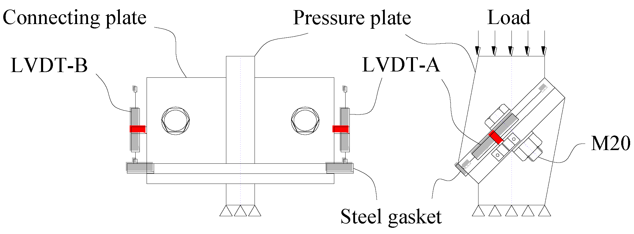
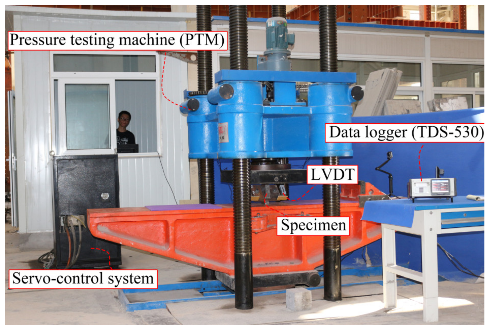
3.2. Loading Conditions and Instruments
4. Test Results and Discussion
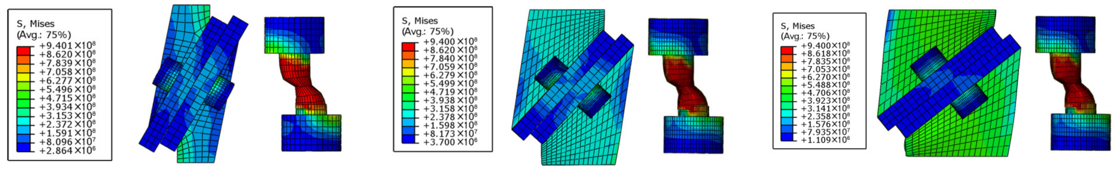
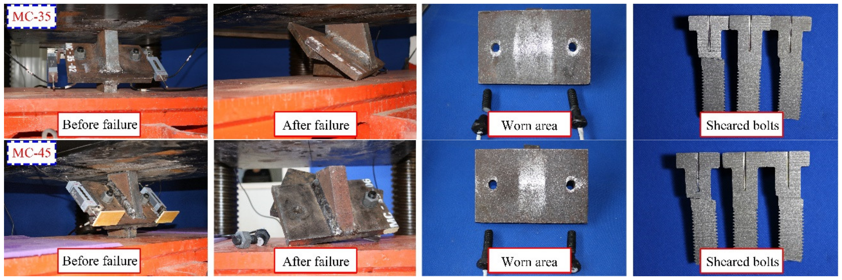
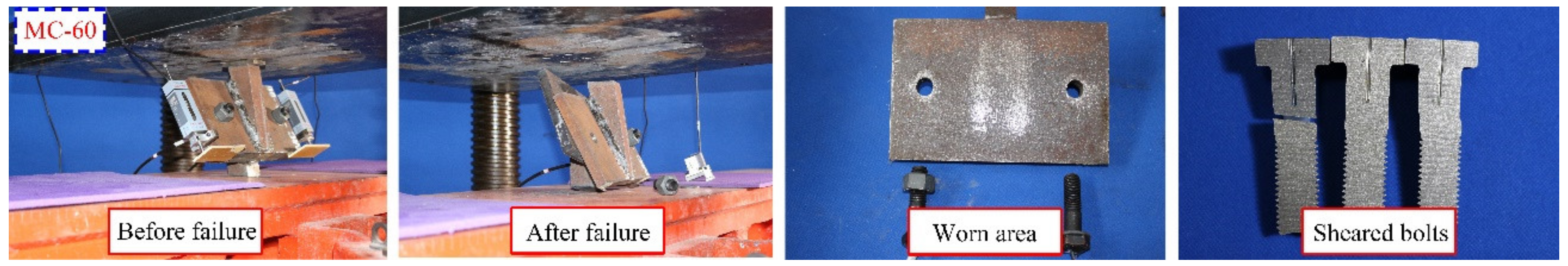
4.1. Failure Modes of FHSB T-Stub Connection
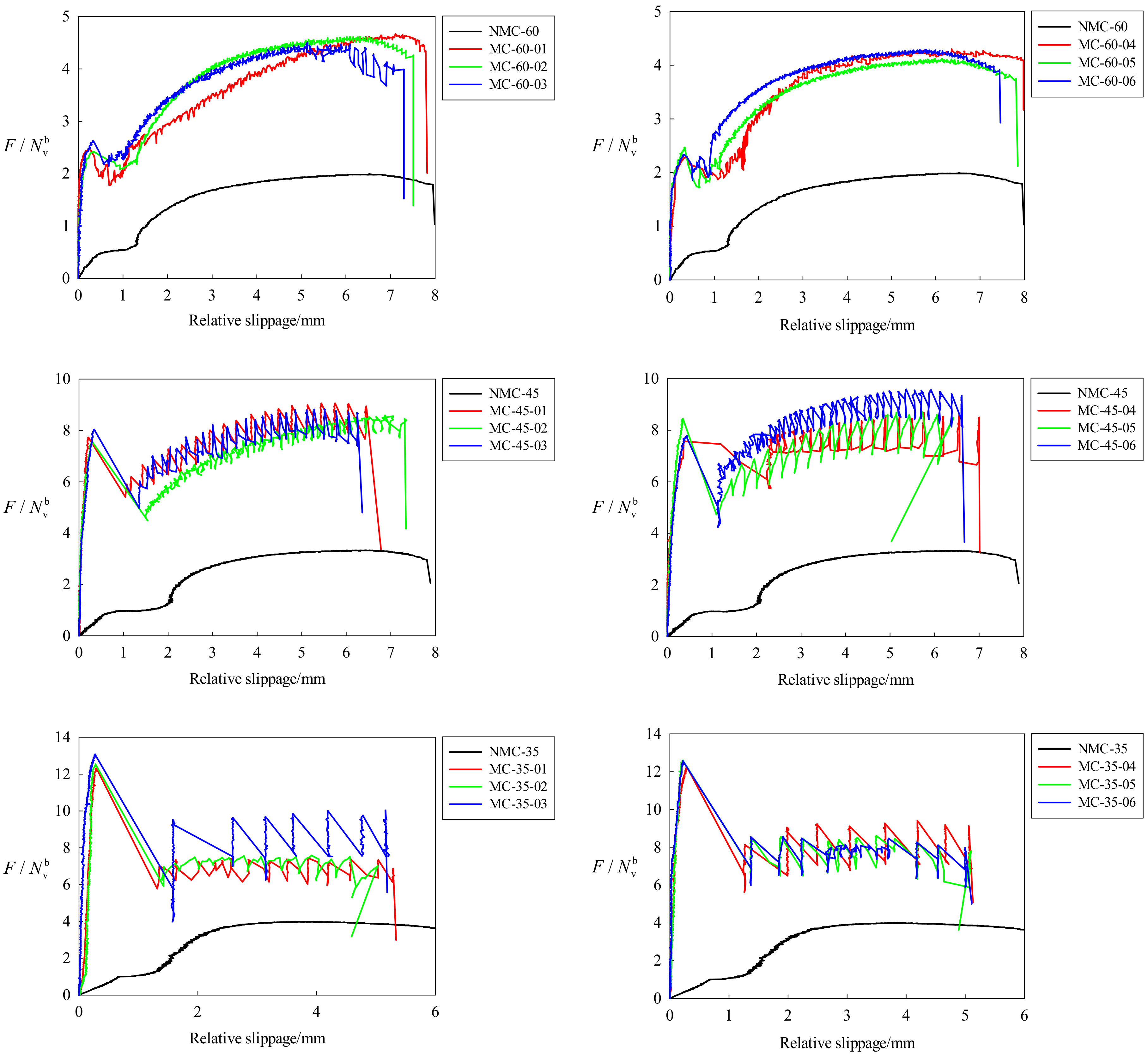
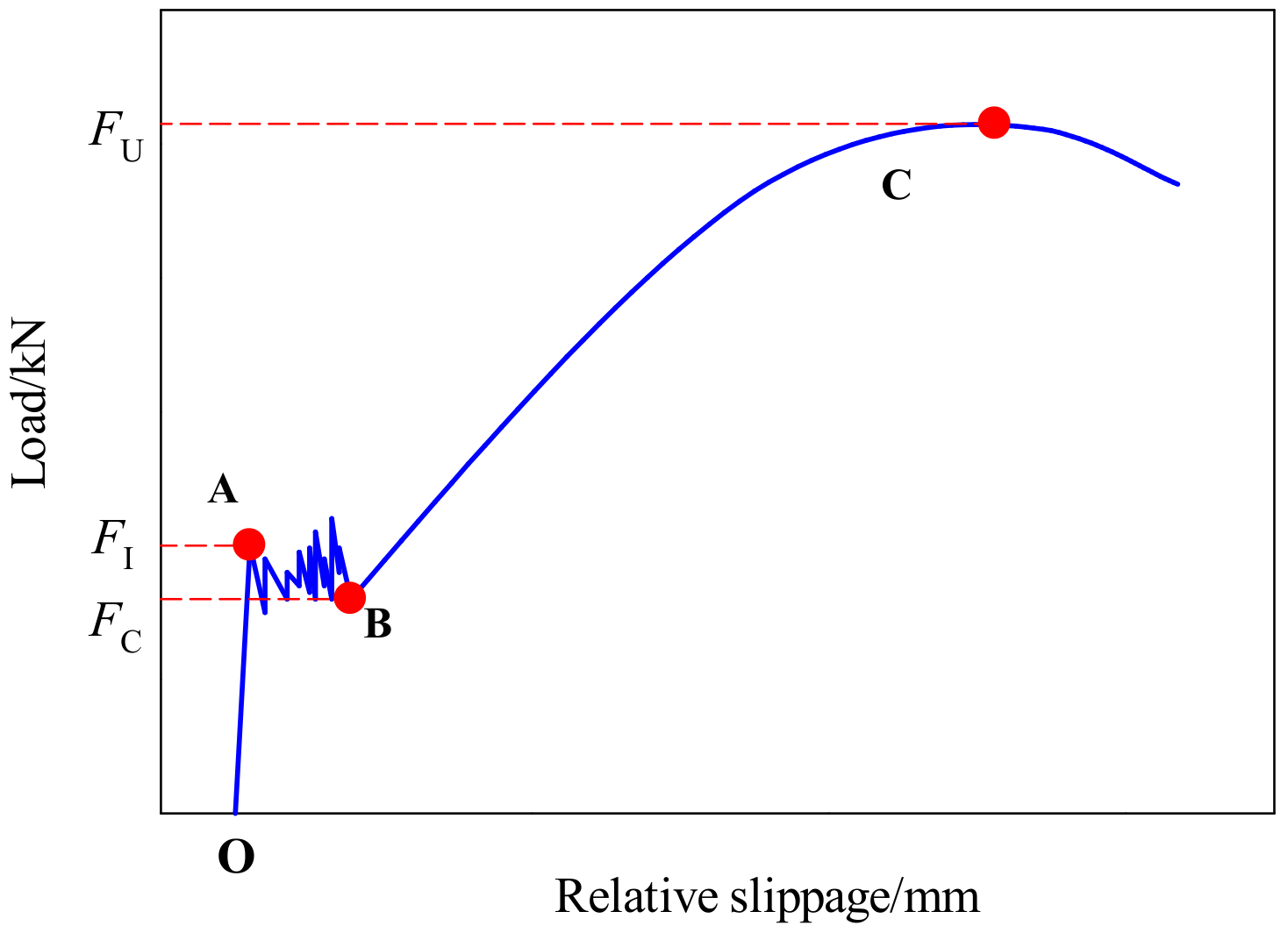
4.2. Relationship between Compressive Load and Relative Slippage of the Two Connecting Plates
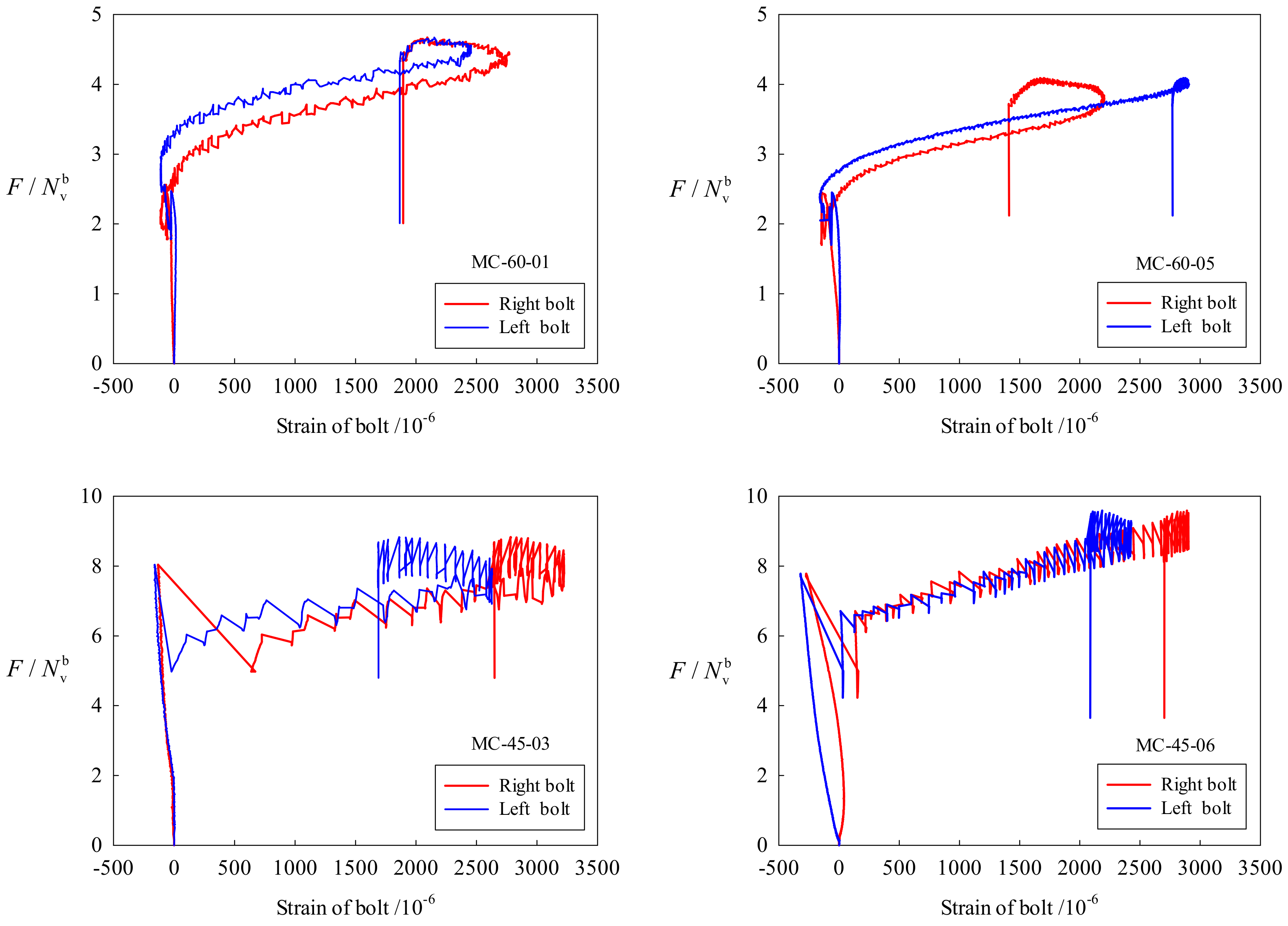
4.3. Relationship between Compression Load and Strains of Bolt
4.4. Relationship between Shear–Compression Ratio and Pressure Features
4.4.1. Initial Friction Load of FHSB T-Stub Connection
4.4.2. Ultimate Strength of FHSB T-Stub Connection
5. Finite Element Method (FEM) based Numerical Simulations
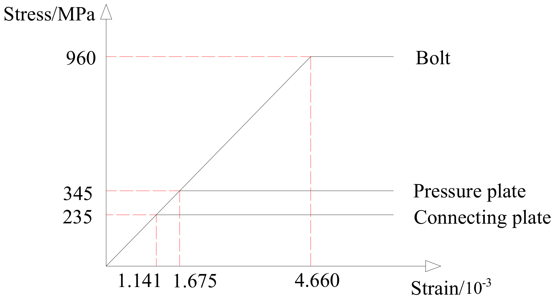
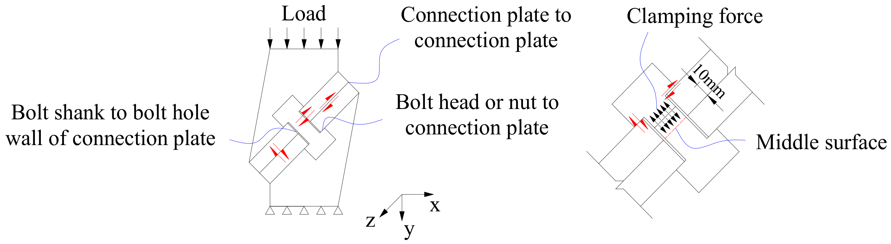
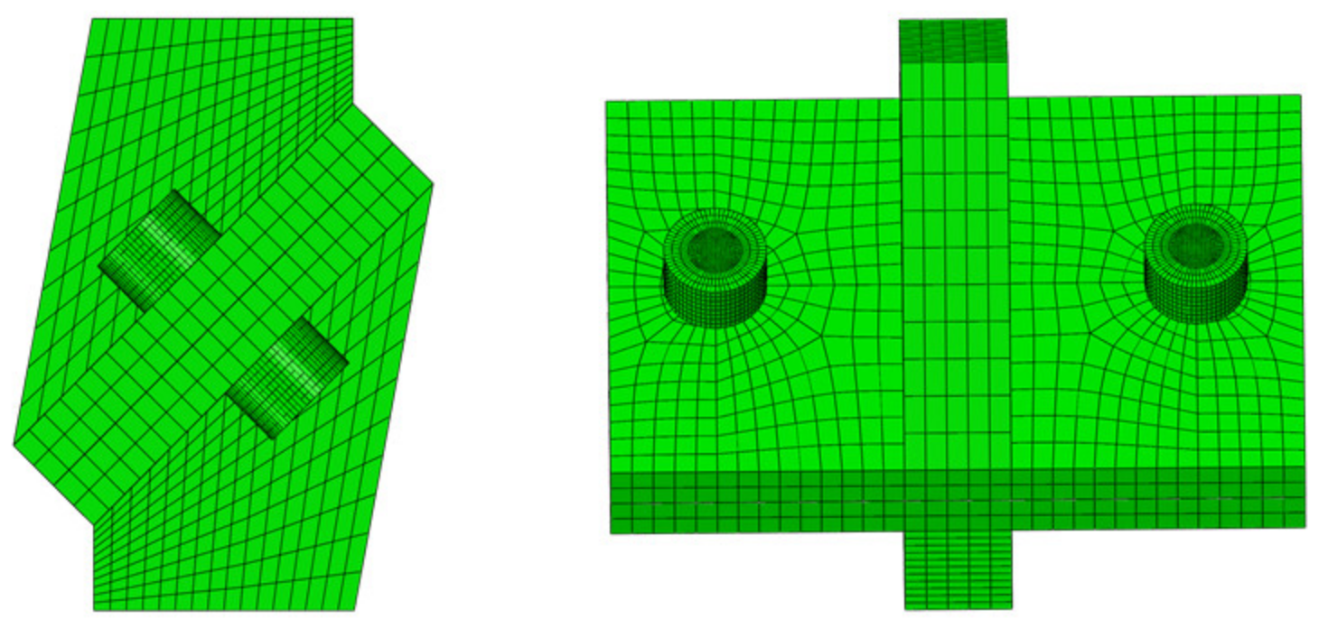
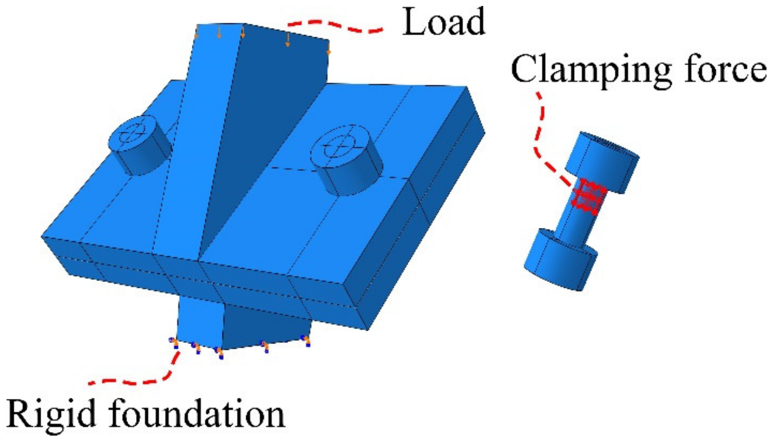
5.1. Finite-Element Modeling
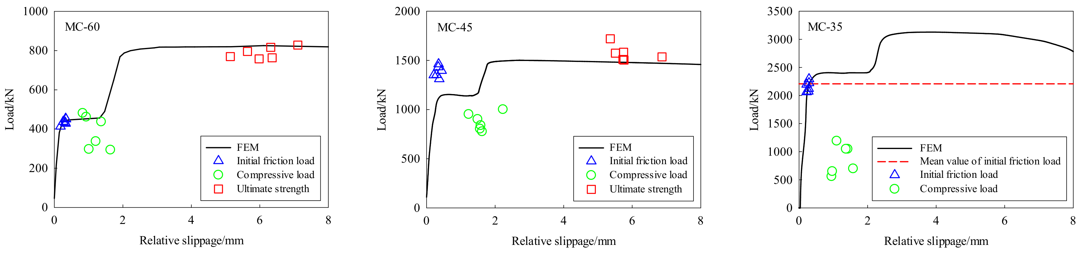
5.2. Validation of Test Results
5.3. Parametric Analysis Results
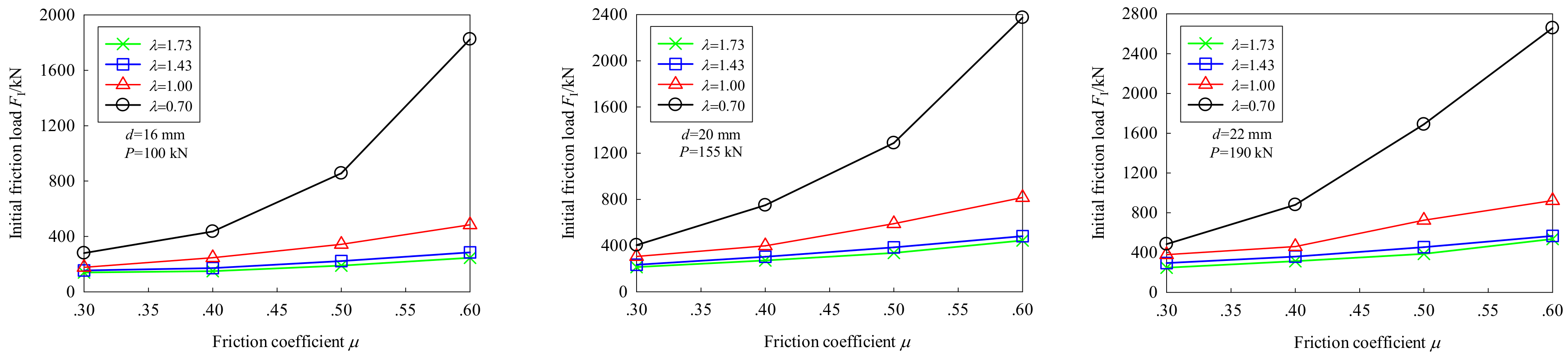
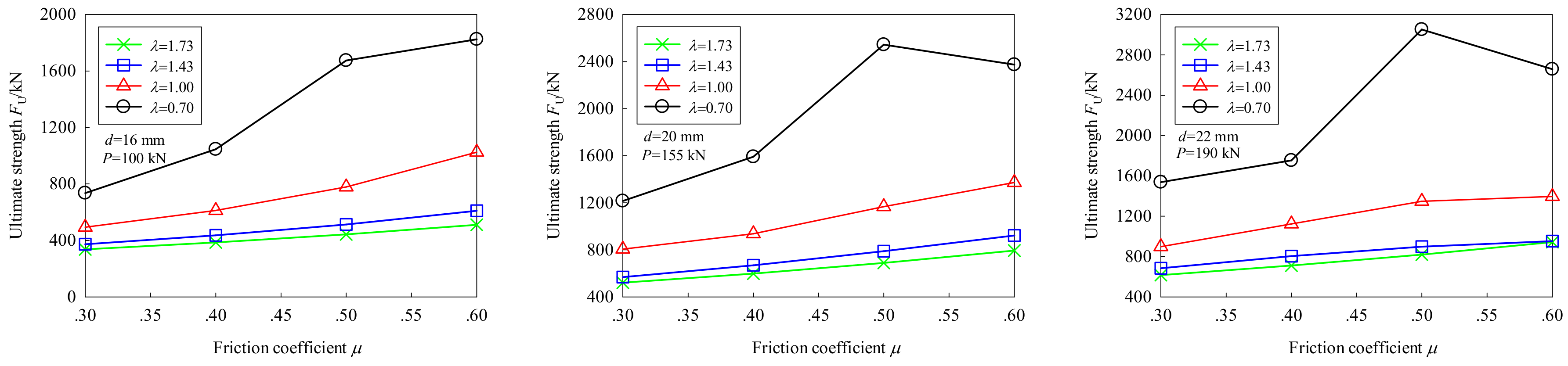
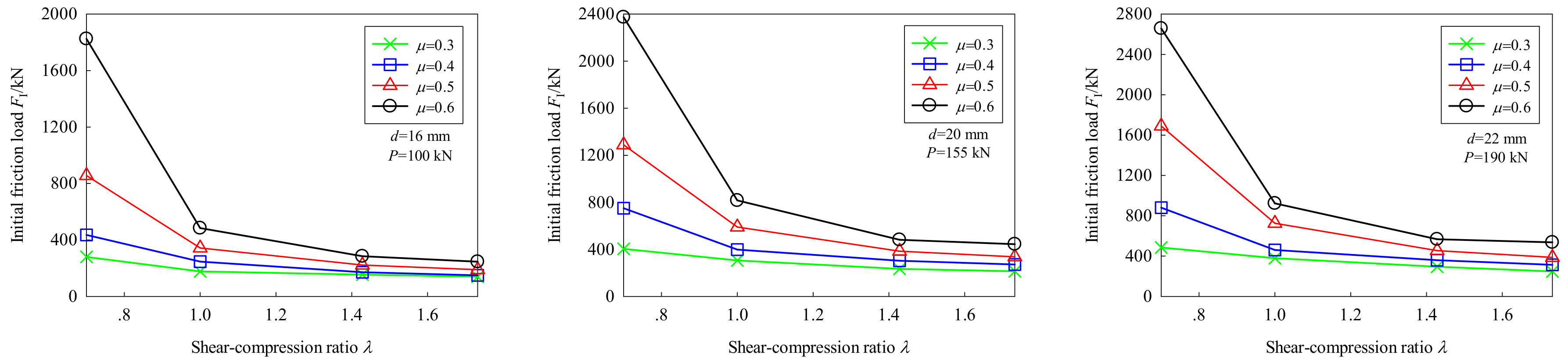
5.3.1. Effect of Friction Coefficient
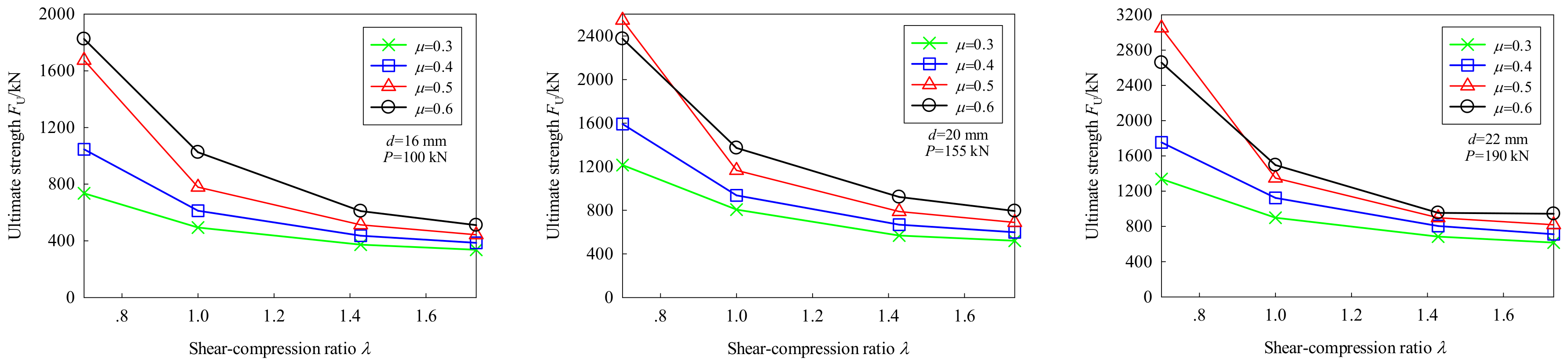
5.3.2. Effect of the Shear–Compression Ratio
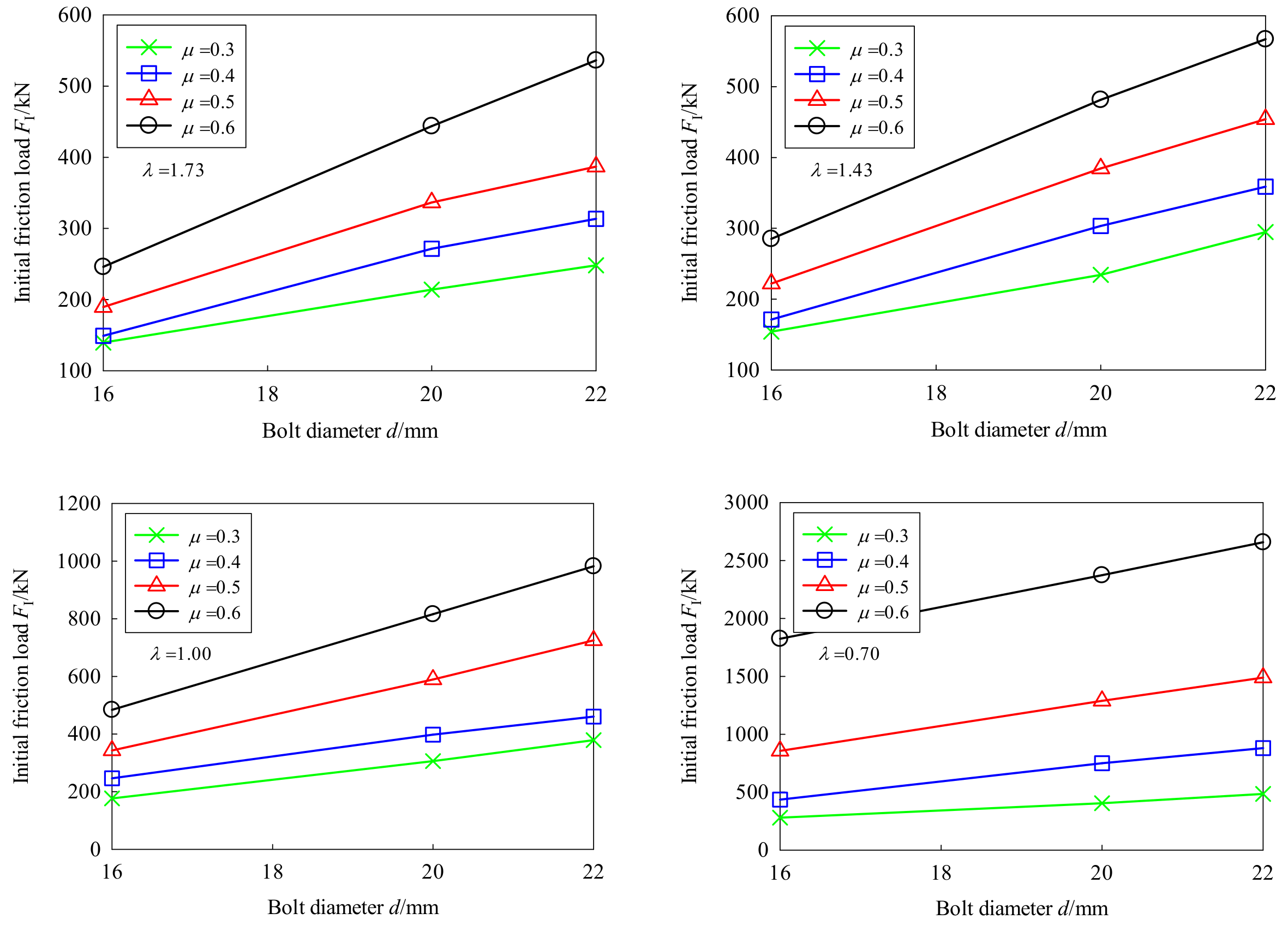
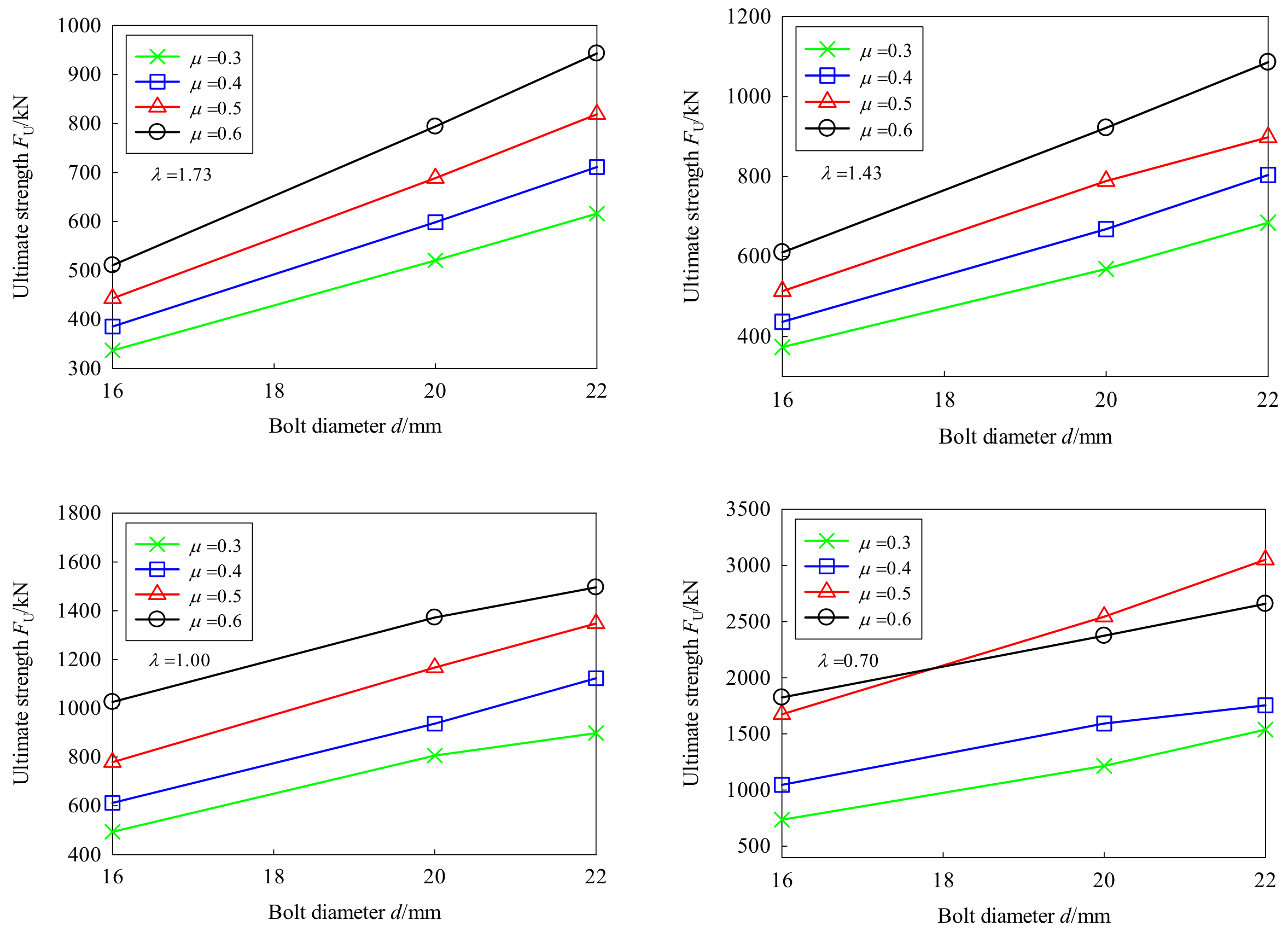
5.3.3. Effect of the Bolt Diameter
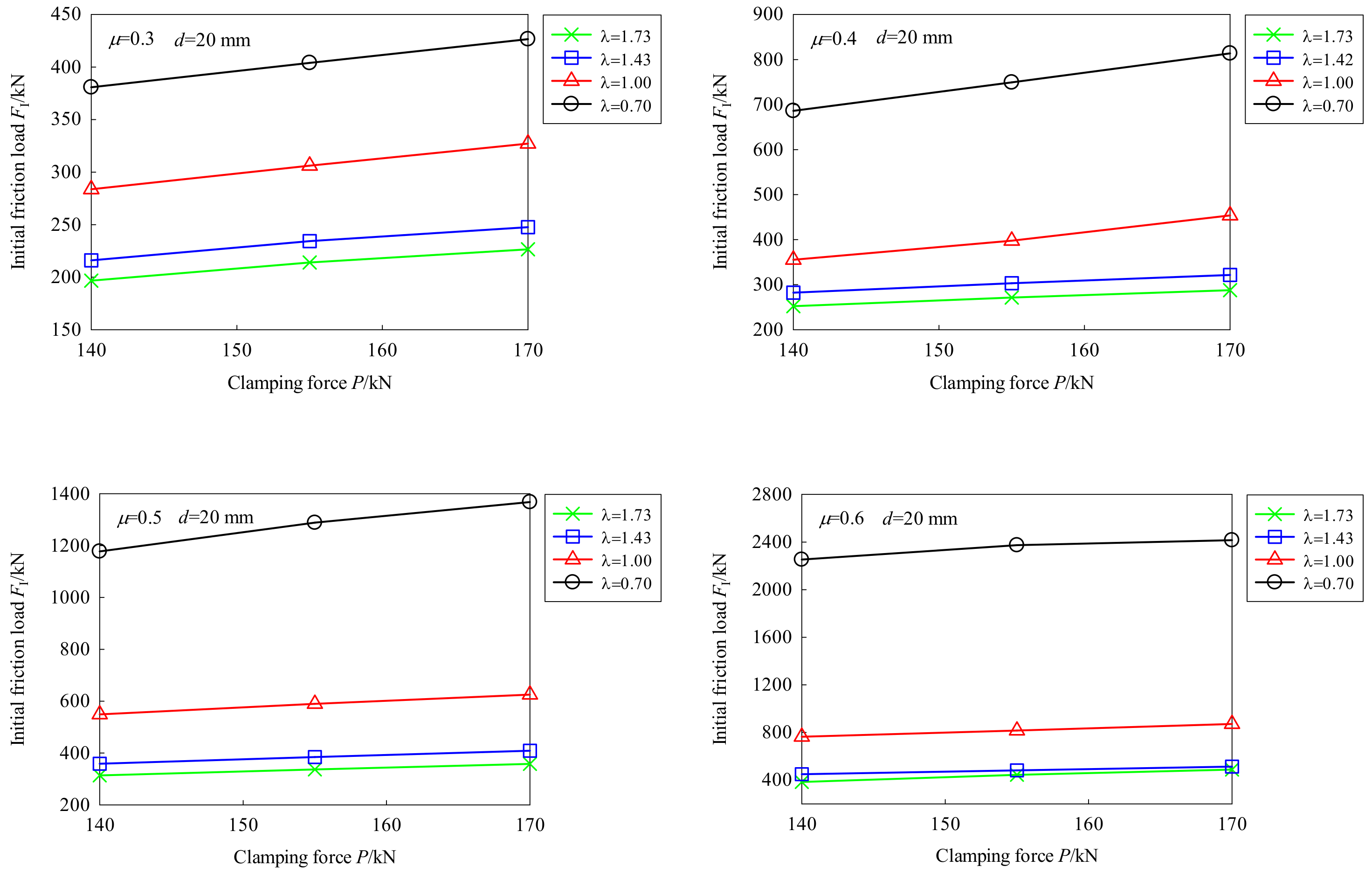
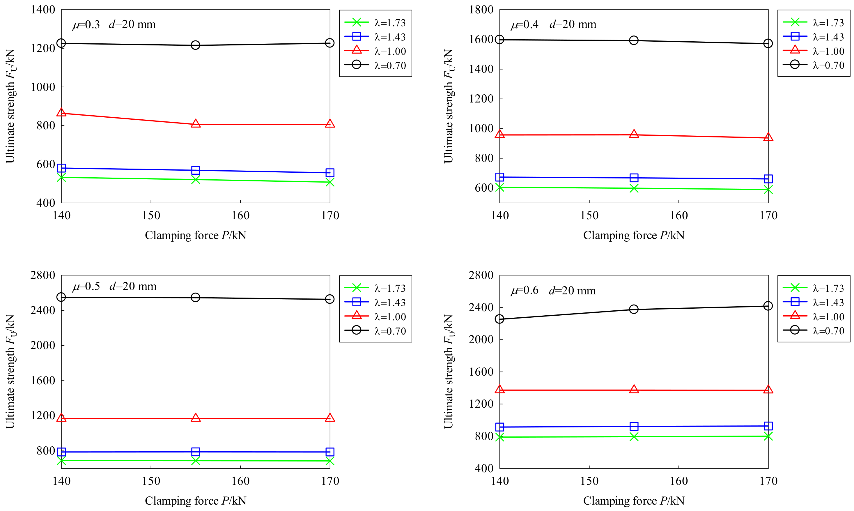
5.3.4. Effect of the Clamping Force
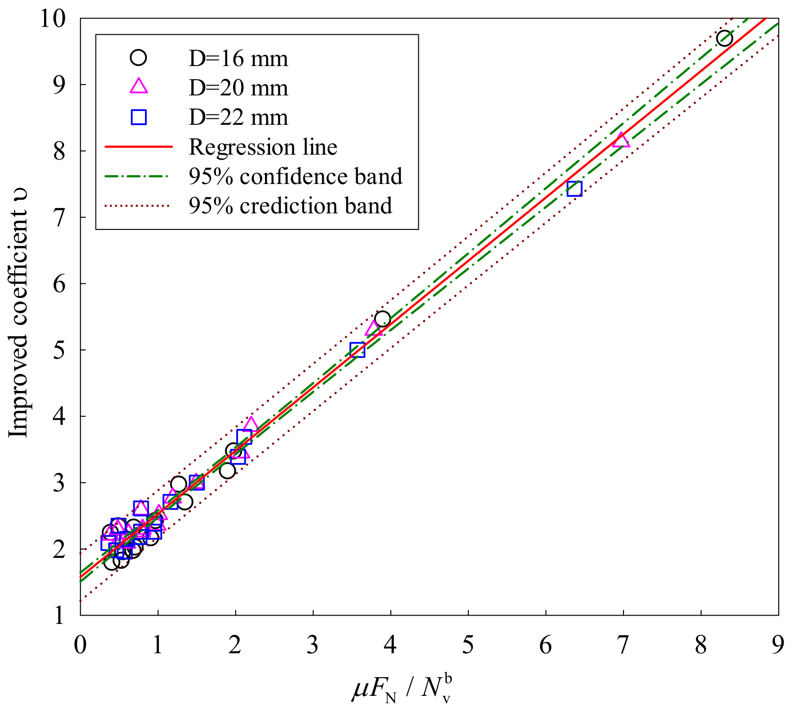
6. Bearing Capacity of the FHSB T-Stub Connection
7. Conclusions
- (1)
- Under the combined effects of shear and compression, the FHSB T-stub connection mainly suffered from bolt shearing failure. The load–displacement curve generally covered four stages: the elastic stage, yield stage, hardening stage and failure stage. If the shear–compression ratio is small and the friction coefficient is large, the ultimate strength of FHSB T-stub connection equals its initial friction load. In this case, the load–displacement curve for the connection only contained the elastic stage and failure stage.
- (2)
- The finite-element model proposed in this paper is suitable to study the mechanical behavior of FHSB T-stub connection under both shear and compression.
- (3)
- The friction coefficient and shear–compression ratio had great impacts on the initial friction load, improved anti-slip coefficient and ultimate strength. The larger the friction coefficient, the smaller the shear–compression ratio, and the better the anti-slip bearing capacity of the FHSB T-stub connection.
- (4)
- The initial friction load and ultimate strength increased linearly with the growing bolt diameter. For every 1 mm increase in bolt diameter, the initial friction load increased by about 10%, while the ultimate strength increased by about 8.5% within a 16–22 mm-diameter.
- (5)
- The initial friction load increased linearly with the increase of clamping force, while the ultimate strength showed a linear decline. For each 10% increase/decrease of the design clamping force within 16–22 mm-diameter bolts, the initial friction load decreased/increased by 7.8%, while the ultimate load remained basically the same.
Author Contributions
Funding
Conflicts of Interest
References
- Sousa, H.; Bento, J.; Figueiras, J. Construction assessment and long-term prediction of prestressed concrete bridges based on monitoring data. Eng. Struct. 2013, 52, 26–37. [Google Scholar] [CrossRef] [Green Version]
- Robertson, I.N. Prediction of vertical deflections for a long-span prestressed concrete bridge structure. Eng. Struct. 2005, 27, 1820–1827. [Google Scholar] [CrossRef]
- Guo, T.; Chen, Z.H.; Liu, T.; Han, D.Z. Time-dependent reliability of strengthened PSC box-girder bridge using phased and incremental static analyses. Eng. Struct. 2016, 117, 358–371. [Google Scholar] [CrossRef]
- Akl, A.; Saiidi, M.; Vosooghi, A. Deflection of in-span hinges in prestressed concrete box girder bridges during construction. Eng. Struct. 2017, 131, 293–310. [Google Scholar] [CrossRef]
- Bažant, Z.P.; Yu, Q.; Li, G.-H. Excessive Long-Time Deflections of Prestressed Box Girders. I: Record-Span Bridge in Palau and Other Paradigms. J. Struct. Eng. 2012, 138, 676–686. [Google Scholar] [CrossRef] [Green Version]
- Chróścielewski, J.; Miśkiewicz, M.; Pyrzowski, Ł.; Sobczyk, B. Damage Analysis of Tensioning Cable Anchorage Zone of a Bridge Superstructure, Using CDP Abaqus Material Model. Arch. Civ. Eng. 2017, 63, 3–18. [Google Scholar] [CrossRef]
- Fjeldheim, F.; Teigen, J. Strengthening of Puttesund Bridge. In Proceedings of the International Conference: Structural Faults and Repair-2003, London, UK, 1–3 July 2003. [Google Scholar]
- Xu, G.N.; Wang, Y.Z.; Wang, S.M.; Wang, L.Y. Key construction techniques for strengthening of main girder of Dongming Huanghe River Highway Bridge. Bridge Constr. 2017, 47, 101–106. [Google Scholar]
- Hedayat, A.A.; Afzadi, E.A.; Iranpour, A. Prediction of the Bolt Fracture in Shear Using Finite Element Method. Structures 2017, 12, 188–210. [Google Scholar] [CrossRef]
- Može, P.; Beg, D. Investigation of high strength steel connections with sevearal bolts in double shear. J. Eng. Struct. 2011, 67, 333–347. [Google Scholar]
- Liu, X.P.; Bradford, M.A.; Chen, Q.J.; Ban, H.Y. Finite element modelling of steel–concrete composite beams with high-strength friction-grip bolt shear connectors. Finite Elem. Anal. Des. 2016, 108, 54–65. [Google Scholar] [CrossRef]
- Manuel, T.J.; Kulak, G.L. Strength of Joints That Combine Bolts and Welds. J. Struct. Eng. 2000, 126, 279–287. [Google Scholar] [CrossRef]
- Chen, Q.; Li, F.X.; Lei, J.Q.; Li, Q.; Guo, J. Tensile capacity and design method of combined connections with bolts and welds. Eng. Mech. 2016, 33, 112–121. [Google Scholar]
- Kim, D.-K.; Lee, C.-H. Experimental and analytical study of combined bolted-welded lap joints including high-strength steel. J. Constr. Steel Res. 2020, 168, 105995. [Google Scholar] [CrossRef]
- Swanson, J.A.; Leon, R.T. Bolted Steel Connections: Tests on T-Stub Components. J. Struct. Eng. 2000, 126, 50–56. [Google Scholar] [CrossRef]
- Lyu, Y.F.; Li, G.Q.; Wang, Y.B.; Li, H.; Wang, Y.Z. Bearing behavior of multi-bolt high strength steel connections. Eng. Struct. 2020, 212, 110510. [Google Scholar] [CrossRef]
- Wang, Y.-B.; Lyu, Y.-F.; Li, G.-Q.; Liew, J.R. Bearing-strength of high strength steel plates in two-bolt connections. J. Constr. Steel Res. 2019, 155, 205–218. [Google Scholar] [CrossRef]
- Ahn, J.-H.; Lee, J.M.; Cheung, J.; Kim, I.-T. Clamping force loss of high-strength bolts as a result of bolt head corrosion damage: Experimental research A. Eng. Fail. Anal. 2016, 59, 509–525. [Google Scholar] [CrossRef]
- Ahn, J.-H.; You, J.M.; Huh, J.; Kim, I.-T.; Jeong, Y.-S. Residual clamping force of bolt connections caused by sectional damage of nuts. J. Constr. Steel Res. 2017, 136, 204–214. [Google Scholar] [CrossRef]
- Lin, W.; Yoda, T.; Taniguchi, N.; Satake, S.; Kasano, H. Preventive maintenance on welded connection joints in aged steel railway bridges. J. Constr. Steel Res. 2014, 92, 46–54. [Google Scholar] [CrossRef]
- Yamaguchi, T.; Suzuki, Y.; Kitada, T.; Sugiura, K. Effect of tensile and shear force on mechanical behavior of high strength bolted tensile joints. J. Constr. Steel Res. 2004, 60, 1545–1560. [Google Scholar] [CrossRef]
- National Standards of the People’s Republic of China. Code for Design of Steel Structure, GB 50017-2017; Ministry of Housing and Urban-Rural Development (MOHURD): Beijing, China, 2017.
- Xu, G.N.; Wang, Y.Z.; Yuan, Q.; Wang, L.Y.; Wu, J.Y. Main girder anchor zone model based experimental study of using cable-stayed system to strengthen Dongming Huanghe River Highway Bridge. World Bridges 2018, 46, 80–85. [Google Scholar]
- Kim, I.-T.; Lee, J.M.; Huh, J.; Ahn, J.-H. Tensile behaviors of friction bolt connection with bolt head corrosion damage: Experimental research B. Eng. Fail. Anal. 2016, 59, 526–543. [Google Scholar] [CrossRef]
- Song, L.S. Anti-sliding bearing capacity of high-strength bolted connections under combined tension and shear. Ind. Const. 1987, 5, 37–42. [Google Scholar]
- Trade Standards of the People’s Republic of China. Guidelines for Design of Highway Cable-Stayed Bridge, JTG/T D65-01-2007; Ministry of Communications: Beijing, China, 2007.
- National Standards of the People’s Republic of China. Technical Specification for High Strength Bolt Connections of Steel Structures, JGJ 82-2011; Ministry of Housing and Urban-Rural Development (MOHURD): Beijing, China, 2011.
- Liu, X.; He, X.; Wang, H.; Zhang, A. Compression-bend-shearing performance of column-to-column bolted-flange connections in prefabricated multi-high-rise steel structures. Eng. Struct. 2018, 160, 439–460. [Google Scholar] [CrossRef]
- Guo, X.; Zhang, Y.; Xiong, Z.; Xiang, Y. Load-bearing capacity of occlusive high-strength bolt connections. J. Constr. Steel Res. 2016, 127, 1–14. [Google Scholar] [CrossRef]
- Dassault Systemes simulia Corp. Abaqus Analysis User’s Manual, 6.11 ed.; SIMULIA: Providence, RI, USA, 2011. [Google Scholar]
- Liang, G.; Guo, H.; Liu, Y.; Li, Y. Q690 high strength steel T-stub tensile behavior: Experimental and numerical analysis. Thin-Walled Struct. 2018, 122, 554–571. [Google Scholar] [CrossRef]
- D’Antimo, M.; Demonceau, J.-F.; Jaspart, J.-P.; Latour, M.; Rizzano, G. Experimental and theoretical analysis of shear bolted connections for tubular structures. J. Constr. Steel Res. 2017, 138, 264–282. [Google Scholar] [CrossRef]
- Gödrich, L.; Wald, F.; Kabeláč, J.; Kuříková, M. Design finite element model of a bolted T-stub connection component. J. Constr. Steel Res. 2019, 157, 198–206. [Google Scholar] [CrossRef]
- Grimsmo, E.; Aalberg, A.; Langseth, M.; Clausen, A. Failure modes of bolt and nut assemblies under tensile loading. J. Constr. Steel Res. 2016, 126, 15–25. [Google Scholar] [CrossRef]
- Liu, X.; He, X.; Wang, H.; Yang, Z.; Pu, S.; Ailin, Z. Bending-shear performance of column-to-column bolted-flange connections in prefabricated multi-high-rise steel structures. J. Constr. Steel Res. 2018, 145, 28–48. [Google Scholar] [CrossRef]


| Size | Bolt/mm | Nut/mm | Washer/mm | ||||||||||
|---|---|---|---|---|---|---|---|---|---|---|---|---|---|
| e | s | K | d | L | b | e | s | m | r | D | d | t | |
| M20 | 38.5 | 33 | 12 | 20 | 75 | 43 | 38.5 | 33 | 20 | 10 | 38.5 | 21.5 | 3.5 |
 |  |  | |||||||||||
| Bolt | Nut | Washer | ||||||
|---|---|---|---|---|---|---|---|---|
| Grade | Yield strength/MPa | Tensile strength/MPa | Elongation/% | Reduction ratio in area/% | Minimum tensile load/kN | Grade | Proof load/kN | Grade |
| 10.9 | ≥900 | 1040 to 1240 | ≥14 | ≥40 | 245 | 10 H | 245 | HRC-45 |
| Specimen ID | θ/° | λ | Surface Treatment | Target Clamping Force /kN | Connecting Plate/mm | Pressure Plate/mm |
|---|---|---|---|---|---|---|
| l × w × t1 | w × a × b × c × t2 | |||||
| NMC-35 | 35 | 0.70 | Butter | 170 | 260 × 170 × 20 | 170 ×130 × 116 × 30 × 40 |
| MC-35-01~06 | 35 | 0.70 | Sand blasting | 170 × 130 × 116 × 30 × 40 | ||
| NMC-45 | 45 | 1.00 | Butter | 170 × 153 × 92 × 30 × 40 | ||
| MC-45-01~06 | 45 | 1.00 | Sand blasting | 170 × 153 × 92 × 30 × 40 | ||
| NMC-60 | 60 | 1.73 | Butter | 170 × 181 × 50 × 30 × 40 | ||
| MC-60-01~06 | 60 | 1.73 | Sand blasting | 170 × 181 × 50 × 30 × 40 |
| λ | Specimen ID | Initial Clamping Force P/kN | Initial Friction Load FI/kN | Compressive Load FC/kN | Ultimate Strength FU/kN | Improved Coefficient ν | |
|---|---|---|---|---|---|---|---|
| Left Bolt | Right Bolt | ||||||
| 0.70 | NMC-35 | 166.8 | 165.6 | - | - | 700.2 | - |
| MC-35-01 | 165.0 | 169.1 | 2179.6 | 1047.5 | 2179.6 | 7.07 | |
| MC-35-02 | 167.6 | 167.5 | 2223.6 | 561.0 | 2223.6 | 7.19 | |
| MC-35-03 | 164.9 | 166.3 | 2293.1 | 1192.2 | 2293.1 | 7.50 | |
| MC-35-04 | 163.9 | 167.3 | 2145.6 | 698.7 | 2145.6 | 7.02 | |
| MC-35-05 | 164.4 | 165.8 | 2208.5 | 650.1 | 2208.5 | 7.25 | |
| MC-35-06 | 163.9 | 165.3 | 2197.3 | 1047.3 | 2197.3 | 7.23 | |
| 1.00 | NMC-45 | 166.5 | 167.2 | - | - | 587.3 | - |
| MC-45-01 | 164.5 | 165.8 | 1350.8 | 952.4 | 1583.2 | 5.46 | |
| MC-45-02 | 169.2 | 168.8 | 1353.7 | 803.4 | 1535.9 | 5.35 | |
| MC-45-03 | 167.9 | 168.9 | 1432.6 | 902.3 | 1573.4 | 5.68 | |
| MC-45-04 | 164.0 | 163.4 | 1310.8 | 1002.3 | 1503.4 | 5.35 | |
| MC-45-05 | 163.7 | 163.7 | 1462.9 | 839.4 | 1509.2 | 5.97 | |
| MC-45-06 | 169.2 | 169.7 | 1395.9 | 776.3 | 1719.6 | 5.50 | |
| 1.73 | NMC-60 | 159.5 | 155.8 | - | - | 331.3 | - |
| MC-60-01 | 167.4 | 168.0 | 437.7 | 293.6 | 828.3 | 2.14 | |
| MC-60-02 | 166.3 | 167.9 | 428.0 | 437.1 | 816.7 | 2.10 | |
| MC-60-03 | 162.8 | 161.8 | 450.5 | 337.1 | 769.5 | 2.27 | |
| MC-60-04 | 168.2 | 167.3 | 413.3 | 481.7 | 763.2 | 2.02 | |
| MC-60-05 | 174.0 | 173.7 | 453.8 | 461.8 | 758.0 | 2.14 | |
| MC-60-06 | 175.7 | 174.6 | 432.6 | 297.1 | 795.9 | 2.02 | |
| Specimen | Initial Friction Load FI | Ultimate Strength FU | ||||
|---|---|---|---|---|---|---|
| Mean Test Value/kN | Simulated Value/kN | Relative Error/% | Mean Test Value/kN | Simulated Value/kN | Relative Error/% | |
| MC-35 | 2207.95 | 2417.11 | 8.65 | 2207.95 | 3134.60 | 29.56 |
| MC-45 | 1384.45 | 1261.34 | −9.76 | 1570.78 | 1370.20 | −14.64 |
| MC-60 | 435.98 | 460.57 | 5.34 | 788.60 | 743.70 | −6.04 |
| Source of Difference | DF | SS | MS | F | p |
|---|---|---|---|---|---|
| Regression | 1 | 126.8280 | 126.8280 | 4199.9847 | <0.0001 |
| Residual | 46 | 1.3891 | 0.0302 | - | - |
| Total | 47 | 128.2170 | 2.7280 | - | - |
© 2020 by the authors. Licensee MDPI, Basel, Switzerland. This article is an open access article distributed under the terms and conditions of the Creative Commons Attribution (CC BY) license (http://creativecommons.org/licenses/by/4.0/).
Share and Cite
Xu, G.; Wang, Y.; Du, Y.; Zhao, W.; Wang, L. Static Strength of Friction-Type High-Strength Bolted T-Stub Connections under Shear and Compression. Appl. Sci. 2020, 10, 3600. https://doi.org/10.3390/app10103600
Xu G, Wang Y, Du Y, Zhao W, Wang L. Static Strength of Friction-Type High-Strength Bolted T-Stub Connections under Shear and Compression. Applied Sciences. 2020; 10(10):3600. https://doi.org/10.3390/app10103600
Chicago/Turabian StyleXu, Gangnian, Youzhi Wang, Yefeng Du, Wenshuai Zhao, and Laiyong Wang. 2020. "Static Strength of Friction-Type High-Strength Bolted T-Stub Connections under Shear and Compression" Applied Sciences 10, no. 10: 3600. https://doi.org/10.3390/app10103600
APA StyleXu, G., Wang, Y., Du, Y., Zhao, W., & Wang, L. (2020). Static Strength of Friction-Type High-Strength Bolted T-Stub Connections under Shear and Compression. Applied Sciences, 10(10), 3600. https://doi.org/10.3390/app10103600