Article

The Mechanical Properties of Centrifuged Concrete in Reinforced Concrete Structures

by
Romualdas Kliukas
1,
Ona Lukoševičienė
1,*,
Arūnas Jaras
1 and
Bronius Jonaitis
2
1
Department of Applied Mechanics, Vilnius Gediminas Technical University, Saulėtekio al. 11, Vilnius LT-10223, Lithuania
2
Department of Reinforced Concrete Structures and Geotechnics, Vilnius Gediminas Technical University, Saulėtekio al. 11, Vilnius LT-10223, Lithuania
*
Author to whom correspondence should be addressed.
Appl. Sci. 2020, 10(10), 3570; https://doi.org/10.3390/app10103570
Submission received: 15 April 2020 / Revised: 7 May 2020 / Accepted: 19 May 2020 / Published: 21 May 2020
(This article belongs to the Section Civil Engineering)

Abstract

:
This article explores the influence of transverse reinforcement (spiral) and high-strength longitudinal reinforcements on the physical-mechanical properties of centrifuged annular cross-section elements of concrete. The test results of almost 200 reinforced, and over 100 control elements are summarizing in this article. The longitudinal reinforcement ratio of samples produced in the laboratory and factory varied from 1.0% to 6.0%; the transverse reinforcement ratio varied from 0.25% to 1.25%; the pitch of spirals varied from 100 mm to 40 mm and the concrete strength varied from 25 MPa to 60 MPa. Experimental relationships of coefficients for concrete strength, moduli of elasticity and limits of the longitudinal strain of centrifuged concrete in reinforced concrete structures in short-term concentrically compression were proposed.

1. Introduction

Concrete members of centrifugally cast annular cross sections are useful in a variety of scenarios, including industrial and hydraulic engineering and energy and transportation engineering design practice [1]. Reinforced concrete annular cross section piers and columns are produced by centrifugation. These elements are reinforced with a longitudinal reinforcement evenly distributed over the entire cross sectional perimeter. The resistance of such elements to mechanical impact is the same in all directions, which makes centrifugal annular piers and columns economical, especially under horizontal loads [2]. Steel spirals are used for transverse reinforcements. Durability, stability, high elasticity, compressive and tensile strength are characteristics of centrifuged, reinforced concrete structures [3].
The strength of bending and eccentric compressive reinforced concrete elements of the annular cross section is more dependent on the strength of the concrete than on the element of the square or I-beam section [2,4,5,6,7,8]. The amount of longitudinal reinforcement in the tensile or compressive zone depends on the position of the neutral axis. Longitudinal high-strength steel reinforcements Are more effective than the conventional ones, with a yield strength of 400 MPa, which prevent the concrete from deforming in the falling part of the stress–strain diagram [9].
In elements of other cross sections, the compressive and tensile reinforcements are most often located in the furthest layers, i.e., those most distant from the neutral axis. This explains why the correct determination of the real strength of centrifuged concrete in both prestressed and non-prestressed tensioned elements of the annular cross sections continues to be a problem.
The strength of the concrete and its other physical and mechanical characteristics in reinforced concrete products may vary considerably from those of the control tests (tests of prisms, cylinders or annular cross-section concrete).
The real compressive strength of centrifuged concrete is in the cylinder strength. The manufacturing and testing process of tubular samples of the annular cross section is complex, and it is difficult to determine this value even for control samples, let alone for the real concrete structures. Indeed, it is common knowledge that concrete strength in real structures can differ significantly from the strength of concrete present in control samples.
Centrifugation is one-way of compacting concrete in order to create a product that is fundamentally different in terms of structure and texture from that produced by means of vibration. Centrifuged concrete has a high tensile strength; the process of centrifugation able to increase the compressive strength of concrete by a factor of two or more. However, the process of centrifugation leads to an anisotropy of the concrete strength and deformability through the wall thickness [10,11,12].
With a thin ring of centrifuged wall, components of the concrete mixture are distributed over the wall thickness, depending on the weight of the particle. For example, coarse aggregates collect closer to the outer surface of the element, finer particles are located between the coarse aggregates. Towards the inner surface the amount of coarse aggregate reduces in concentration and the sand is evenly distributed in the cement stone. The inner layer of the surface consists of cement, fine aggregate particles and a sludge [13,14].
Centrifugation of the concrete allows water filtration in the mixture from one layer to another, so that capillaries extending from the outer to the inner surface form in the centrifuged concrete. These join together to form macrocapillaries in the middle of the element wall, which reduces the strength of concrete. The intensity and amount of microcapillaries depend on the initial water and cement ratio in the concrete mixture. The residual w/c ratio (which is independent of the initial mixture w/c ratio) will be between 0.30 and 0.32 [14,15,16] when the optimal centrifugation time and pressing pressure is reached.
The strength of the concrete changes at different points throughout the thickness of the wall of the centrifuged element. A high resistance of concrete is found at the outer surface of the element, with the weakest in the inner surface [10,11,12]. This difference can be up to 20% for thin-walled (wall thickness up to 70 mm) centrifuged elements [13,17,18].
The anisotropy of the texture and density of concrete in the wall of centrifuged element changes the strength, deformability and other physical-mechanical properties [16].
Reinforcement can affect the conditions of compaction and curing of concrete, the values of shrinkage stresses, the occurrence of additional damage to concrete, the redistribution of stresses between concrete and reinforcement and the stress–strain state of the concrete inside the spiral [19].
There was much research during the 1950 s and 1970 s into the mechanical and technological properties of centrifuged concrete, at a time when increasing overhead powerlines were being erected throughout the world, which required a commensurate number of poles to support centrifuged power lines [3,20,21]. Nevertheless, evidence for the influence of longitudinal and transverse reinforcements on the mechanical properties of centrifuged concrete during production is mostly absent in scientific literature. Reinforcement is an important factor and does affect the mechanical properties of centrifuged concrete.
In recent year’s there was more research on the use of FRP reinforcement, as well as on vibrated concrete structures reinforced with longitudinal and transverse FRP reinforcement. Numerous articles [19,22,23,24,25,26,27,28,29,30,31] have be published on the work of full circular cross section concentrically and eccentrically loaded concrete columns reinforced with FRP and GFRP and on the physical-mechanical properties of concrete. Our conclusions do not suggest an assessment of the influence of spiral reinforcement on the bearing capacity or deformability of annular cross section of centrifuged reinforced concrete structures.
Various experimental studies provided new data on physical and mechanical properties of centrifuged concrete (i.e., strength, deformability and durability) under varying and maintenance conditions [1,18,32]. The results obtained in these studies allowed the researchers to define the applied theories to predict strength, toughness, reliability, durability and resistance to cracking of differently reinforced elements of annular cross section more exactly. With the introduction of a new generation of reinforcement (high-strength metal and FRP) and various additives that improve the properties of concrete mixture, the improvement of structural production technologies made it necessary to expand experimental research [1,2].
The purpose of this study is to analyze the physical and mechanical properties of centrifuged concrete structures reinforced longitudinal and transverse reinforcement. The physical-mechanical properties of concrete in real structures may differ significantly from the control concrete samples. Physical-mechanical properties of centrifuged elements depend on composition of concrete, technology of their production, longitudinal and transverse reinforcement, wall thickness of elements. The presented and analyzed experimental research data provide some recommendation for engineers.

2. Materials and Methods

2.1. Materials

Reinforced concrete samples of centrifugal annual cross section were made of concrete with a strength of 25 MPa to 60 MPa. Washed crushed granite (large fraction from 5 mm to 20 mm), sand and cement with an activity of 52 MPa was used for the concrete mixture. Samples of concrete of centrifugal annual cross-sectional (control) and centrifuged concrete prisms were manufactured from the same concrete mixture in the same form along with the reinforced concrete specimens (Figure 1a).
The high-strength reinforcement bars with a diameter of 10, 12 and 14 mm were used as longitudinal reinforcement. The mean values of the 0.2%-proof-stress f0.2 and ultimate tensile strength fu of reinforcement were 1060, 890, 868 MPa and 1260, 1052, 1138 MPa, respectively. The deformed steel wire of 4 or 5 mm in diameter with ultimate tensile strength 630 or 670 MPa is used for transverse (spiral) reinforcement.

2.2. Mixture Design and Reinforcement Frames

The concrete mixture consisting of cement, sand, crushed granite and water are presented in Table 1. Due to the centrifugation process, a part of the water and cement additives were removed from concrete mixtures. Therefore, their initial water–cement ratio varied from 0.41 to 0.65 decreased to the residual water–cement clinker ratio from 0.31 to 0.33.
Reinforcement frames are made from longitudinal and transverse reinforcement. The number of longitudinal reinforcement bars in the reinforced concrete samples ranged from 6 to 51. The ratio of longitudinal reinforcement µs varied from 1.0% to 6.0%, while the ratio of transverse reinforcement µcir from 0.25% to 1.25%, with a corresponding lead of the spirals: from 40 mm to 100 mm. Examples of reinforcement frames are presented in Figure 1b,c.

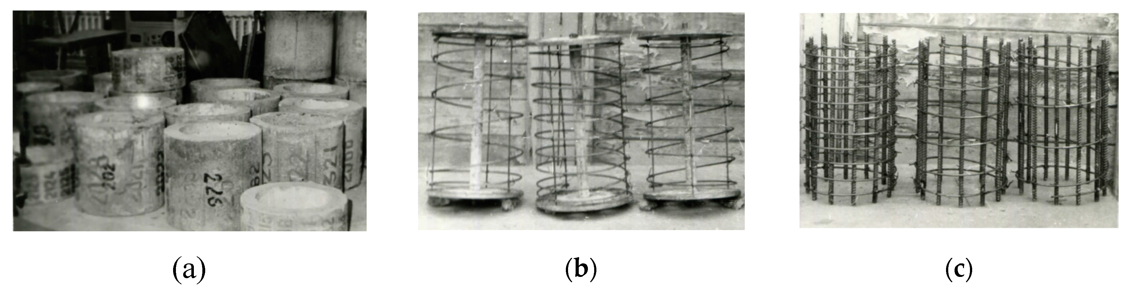
2.3. Centrifuged Concrete and Reinforced, Centrifuged Concrete Specimens Preparation and Curing

Approximately 193 reinforced concrete and 125 concrete specimens were tested for the influence of longitudinal, transverse, longitudinal and transverse reinforcement on the strength and deformability of centrifuged concrete. The samples with an external diameter of 260 mm or 500 mm, height of 400 mm or 800 mm and wall thickness from 35 mm to 80 mm were produced using single-layer centrifugation. Table 2 presents a research plan for the transverse, longitudinal and both longitudinal and transverse reinforcement effect on the strength and deformability of the centrifuged annular cross-section concrete elements. The specimens were prepared by centrifugation in support of a radial or belt type centrifuge in the factory (group BA) and laboratory (groups A, BK, C1, C2, C3) conditions. Special metal diaphragms were used to form the specimens. All specimens curing under natural conditions for about 3 to 4 days in molds, and after disassembly they were stored under natural (temperature–humidity) conditions.
A previous study by Makarov A. S [10] showed that the optimal pressure at the outer diameter 500 mm of the elements is 0.1–0.2 MPa and for 260 mm is 0.01–0.02 MPa. In this case, centrifugation time is recommended from 10 to 15 min, respectively.

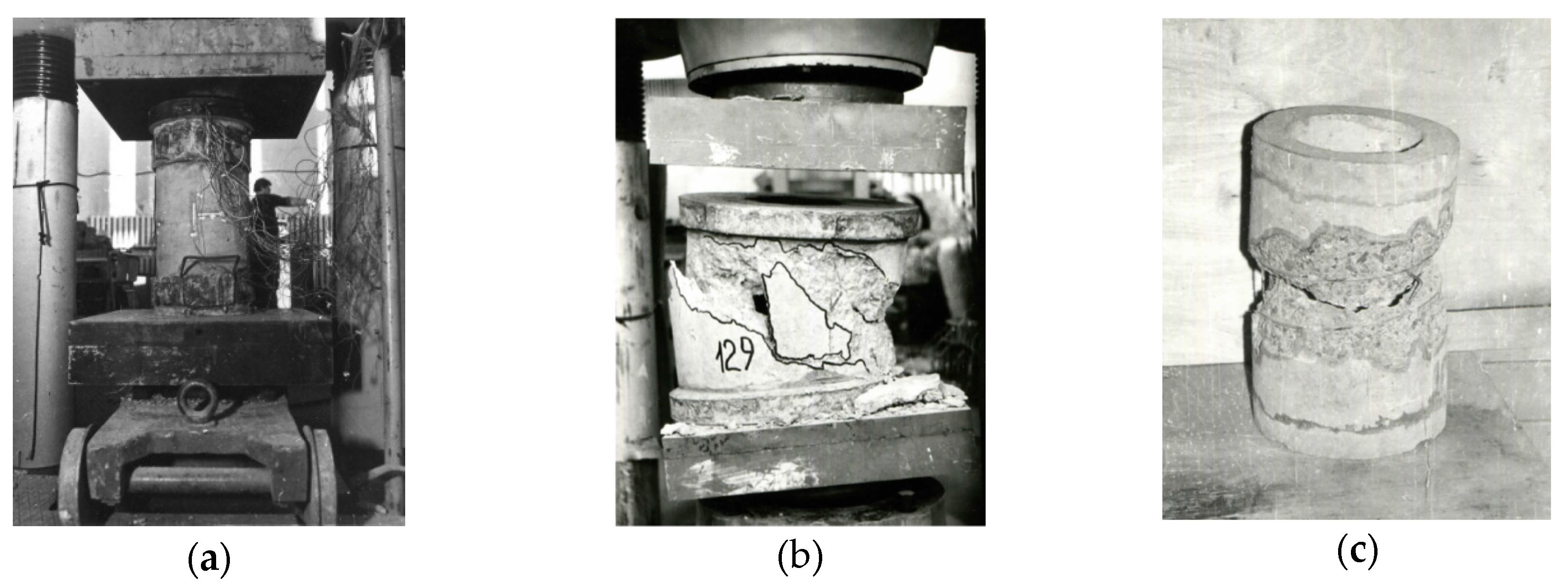
2.4. Mechanical Tests of Specimens

Concrete and reinforced concrete elements were tested for short-term compression, 100 days after the specimens were dismantled. Previous investigations [14,18] shows that the increase in the strength of centrifuged concrete after 100 to 120 days of hardening under ambient conditions is significant (the strength remained virtually unchanged during the test period). In this way, variation in the strength of the concrete during the test period was avoided.
A metal plate with a clip was fitted to each end of the specimen and attached using cement mortar to distribute the load uniformly and also to prevent splitting. Previous studies [14,32] have shown that the scaling effect occurs in annular cross-section elements at the height of element, which is equal to the wall thickness of it, that is about from 30 to 60 mm from the press support. During the test, the load was progressively increased from 5 to 10 min, which represented about 7%–10% of the destructive load. For one specimen the duration of the test from the beginning of loading until disintegration was about from 50 to 60 min (Figure 2a–c).
Longitudinal and transverse strains at the start and finish of each loading stage of the specimen were measured with strain gauges at a base of 50 mm. The strains were measured on 4 sides over the entire height of the specimen, transverse strains were measured in the middle cross section of the entire height of the specimen. In addition, mechanical clock-type indicators measured longitudinal strains with a measuring base of 200 mm or 500 mm and measured with strain gauges on each reinforcement bar. The transverse reinforcement strains were measured at 4 to 6 points in the middle cross section, according to the height of the specimens. At the loading stages—and prior to breaking point—the impedance of the strain gauges was set using an automatic electronic system and readings from the mechanical indicators were recorded visually.

3. Assessment of Mechanical Properties for Specimens

This study analyzed the effect of longitudinal and transverse reinforcement on the elasticity modulus Ecs of reinforced high-strength centrifuged concrete, concrete strength fcs and longitudinal concrete strains εcs1 matching this strength and longitudinal strains εcs2, of the reinforced elements when the maximally allowed load N2 (Figure 3) was applied.
The longitudinal reinforcement significantly influences the deformability (the value of longitudinal strains) of the reinforced concrete element only when the stresses in concrete reaches its maximum and when plastic deformation has not yet occurred in the reinforcement. At this point, the concrete breaks down, but deforms plastically in the downward part of the σε diagram until the stresses in the reinforcement reach the yield state. A high-strength (yield strength more than 800 MPa) longitudinal reinforcement is currently using for reinforcement in most centrifuged concrete structures [2]. It can significantly influence the redistribution of action effects between concrete and reinforcement by loading the reinforced concrete element (Figure 3).
However, it is difficult to make a quantitative evaluation of this assumption because stresses in the reinforced concrete elements of the annular cross section are determined indirectly.
f c s = N c , m a x A c = ( N 1 N s 1 ) A c = ( N 1 ε c s 1 E s A s ) A c
where Nc,max is the maximum load carried by the concrete of a reinforced concrete element; N1 is the load carried by a reinforced concrete element; Ns1 is the axial load carried by reinforcement; Ac and As are cross-sectional areas of concrete and reinforcement, respectively; Es is the modulus of elasticity of reinforcement; εcs1 is the compressive strain in the concrete at the peak stress fcs.

3.1. The Effect of Transverse Reinforcement for Mechanical Properties of Reinforced, Centrifuged Concrete Elements

The transverse reinforcement in the vibrated elements significantly influences their behavior, especially during the collapse stage—and at the same time—changes the physical-mechanical properties of the reinforced concrete: it increases the values of limit strain and stress of the concrete.
The scientific literature has little to say on the behavior of hollow concrete elements reinforced with only transverse reinforcement. Moreover, the work of the full circle and annular cross-section elements is fundamentally different due to the stress–strain state of concrete, the stability conditions of the longitudinal reinforcement and finally, their cost-effectiveness.
The effect of the transverse (spiral) reinforcement on the modulus of elasticity on the strength and strains of the centrifuged concrete, can be evaluated by the following formulae:
α c i r 1 = E c c i r / E c
α c i r 2 = f c c i r / f c
α c i r 3 = ε c c i r / ε c u
where Eccir is the modulus of elasticity of concrete reinforced by transverse (spiral) reinforcement; fccir is the strength of concrete reinforced by transverse reinforcement; εccir denotes longitudinal strains of concrete reinforced by transverse reinforcement, matching the carrying capacity of the element; Ec is the modulus of elasticity of concrete; fc is the compressive strength of concrete; εcu denotes the compressive strain of concrete at the peak stress value fc.

3.2. The Effect of Longitudinal Reinforcement for Mechanical Properties of Reinforced, Centrifuged Concrete Elements

Few data were obtained in studying the performance of the compressed reinforced, centrifuged concrete elements with longitudinal reinforcement of high strength. A specific method of concrete reinforcement and compaction in centrifugation compared to the reinforced concrete made of vibrated concrete allows us to state that longitudinal reinforcement can affect the formation of the structure of centrifuged concrete and the conditions of concrete compaction and hardening, as well as the mechanical properties of centrifuged concrete [17]. The effect of longitudinal reinforcement on the modulus of elasticity and compressive strength of reinforced, centrifuged concrete are evaluated by using the dimensionless coefficients αs1 and αs2:
α s 1 = E c s / E c
α s 2 = f c s / f c
where Ecs is the modulus of elasticity of reinforced concrete elements; fcs is the compressive strength of centrifuged concrete of reinforced members. Thus, the coefficient αs2 expresses a general effect of longitudinal reinforcement on the concrete strength both in the process of concrete production and loading.
The influence of longitudinal reinforcement on the longitudinal strain εcs1 of reinforced, centrifuged concrete and the longitudinal strain εcs2 of the reinforced element can obtain by evaluating the coefficients αs3 and αs4 as follow:
α s 3 = ε c s 1 / ε c u
α s 4 = ε c s 2 / ε c u
When high-strength reinforcement with the relative yield strength fs,0.2 ≈ 850–900 MPa is used for longitudinal reinforcement; the limiting strains εcs2 of the compressed reinforced concrete element, matching its load-carrying capacity, should increase (Figure 3). This increase the coefficient of the reinforcement strength usage, although this reinforcement was characterized by elastic performance before the failure of the compressed element.

3.3. The Combined Effect of Longitudinal and Transverse Reinforcement for Mechanical Properties of Reinforced, Centrifuged Concrete Members

The effect of transverse and longitudinal reinforcement on the resistance and the initial modulus of elasticity of centrifuged concrete caused by the changes in the manufacturing and curing conditions (as well as by the appearance of the casing effect for reinforced concrete elements of annular cross section) can be both positive and negative.
Most design regulations recommend that the optimal pitch of transverse reinforcement for structures of annular cross section should be equal to 100 mm. However, these structures have some areas where a smaller spiral pitch is required or recommended to ensure the anchoring of prestressed or non-prestressed longitudinal reinforcement. In specific structures that are considered to be important to structural integrity or structures used in cold climates, the compaction of transverse reinforcement is used to ensure reliability and carrying capacity. The aim here is to increase concrete strength and avoid fragile and sudden structural failure. However, as mentioned above, the compaction of reinforcement can change the physical and mechanical properties of centrifuged concrete. In structures with a diameter of 260 mm, having ~50 mm thick walls and the ratio of reinforcement μs ≈ 3.0% and μs ≈ 6.0%, the distance between the axes of longitudinal reinforcement bars is ~50 mm and 30 mm, respectively. Hence, when a 5.0 mm diameter is used for transverse spiral reinforcement and when the spiral pitch changes the hole of the reinforcement mesh, which varies from 40 × 95 mm to 40 × 35 mm (for the ratio of reinforcement μs ≈ 3.0%) and from 25 × 95 mm to 25 × 35 mm (for the ratio of reinforcement μs ≈ 6.0%), then this has a strong negative effect on the conditions of concrete formation and curing. The concrete structure in the cross section can also change, which, in turn, will affect its physical and mechanical properties as well.
The combined effect of the longitudinal and transverse reinforcement on the initial modulus of elasticity and the strength and the strains of centrifuged concrete can be evaluated using the following formulae:
α 1 = E c s , c i r / E c
α 2 = f c s , c i r / f c
α 3 = ε c s 1 , c i r / ε c u
α 4 = ε c s 2 , c i r / ε c u
where Ecs,cir is the modulus of elasticity of longitudinal and transverse (spiral) reinforcement reinforced concrete; fcs,cir is concrete strength of longitudinal and transverse reinforcement reinforced concrete; εcs1,cir is a longitudinal strain of longitudinal and transverse reinforcement reinforced concrete, matching maximal stress in the reinforced element; εcs2,cir is a longitudinal strain of longitudinal and transverse reinforcement reinforced concrete, matching resistance of the reinforced element.

4. Experimental Results and Their Analysis

4.1. The Effect of Transverse Reinforcement

Experimental results of samples series A reflecting the effect of transverse reinforcement for physical-mechanical properties of annular cross section of centrifuged concrete are presented in Figure 4. The authors are analyzed the ratio of transverse (spiral) reinforcement µcir = 0.25% to 1.25%, concrete strength fc = 30 MPa to 50 MPa and relative wall thickness of annular cross section element β = t/r1 = 0.25 to 0.4.
The effect of the spiral reinforcement on the modulus of elasticity Eccir, on the cylindrical strength fccir and strain εccir of the centrifuged concrete, should be evaluated by the following formulae:
α c i r   1 1
α c i r 2 = 0.81 + 0.9 μ c i r 0.6 μ c i r 2
α c i r 3 = 1 + 0.7 μ c i r ( 1 0.01 f c 0.16 μ c i r )
Thus, experiments (Figure 4) demonstrate that the intensity of the spiral reinforcement has practically no effect on the modulus of elasticity of the centrifuged concrete. The reason for this is that in the initial stage of loading in which the initial modulus of elasticity is determined, i.e., under relatively low stresses, the reinforcement has no noticeable effect on the stress–strain properties of concrete without microcracks.
Short-term compression tests have shown that longitudinal strains of reinforced concrete specimens with transverse spiral reinforcement were larger by 10%–25% than those of the specimens not reinforced by spiral reinforcement. These results match the scarce data provided by other authors [32] on testing the specimens of annular cross section reinforced by transverse (spiral) reinforcement. The experiments conducted by authors and by Kvedaras A. [32] have shown that the mechanical properties of centrifuged concrete are influenced not only by longitudinal reinforcement, but also by transverse reinforcement. This influence is similar to the effect produced on concrete by the core of the column’s casing with confinement reinforcement. It was stated that a decrease in the pitch of the spiral (with a ratio of transverse reinforcement µcir = 0.25% to 1.25%) causes an increase in the structural compressive strength of concrete up to 20% [2,18]. This relatively insignificant effect of the transverse reinforcement on the structural strength of the centrifuged concrete may be accounted for by the fact that the stress–strain state of the tubular sample is closer to the two-dimensional (plane) state than to the three-dimensional state. It is known [32] that plane biaxial compression has no effect on the strength of concrete. It is close to its prism strength.

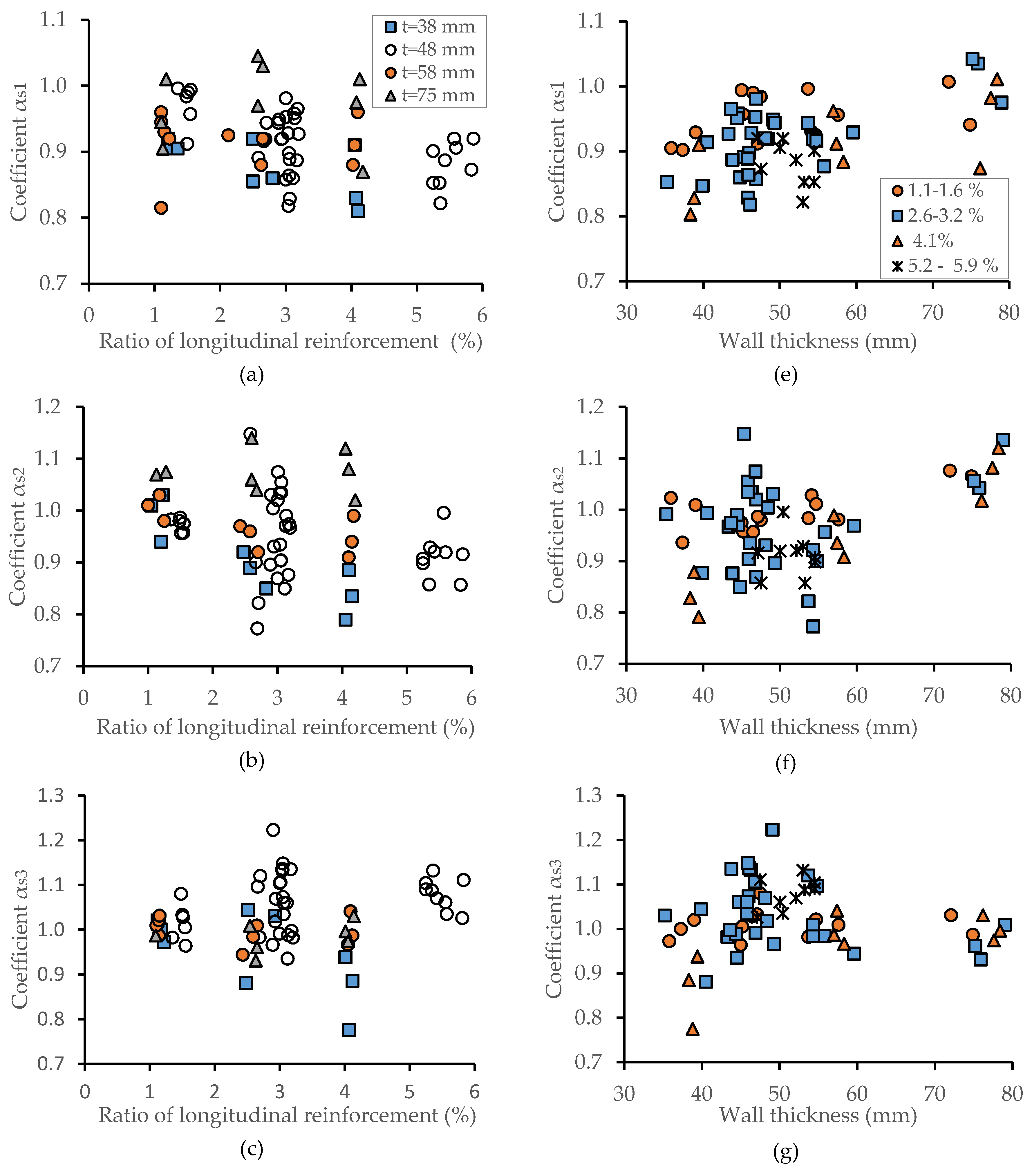
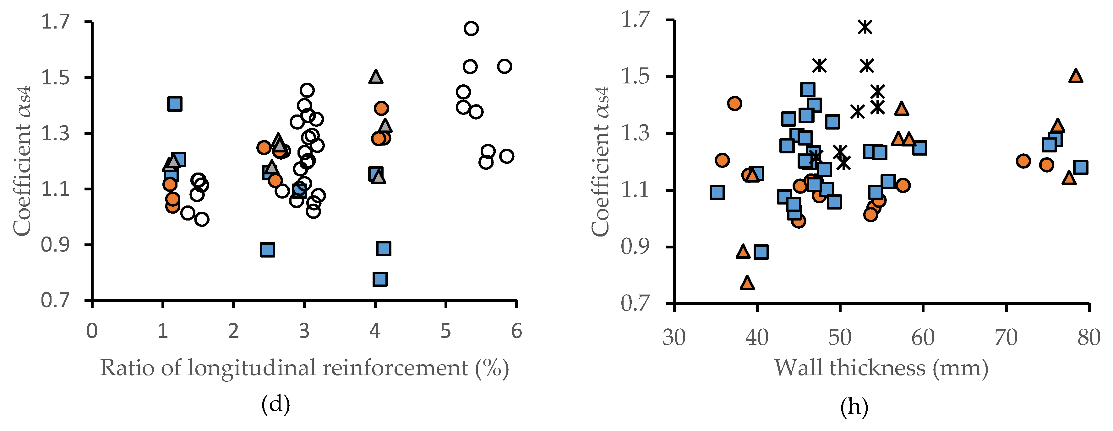
4.2. The Impact of Longitudinal Reinforcement

The results of the experimental studies samples series B, reflecting the effect of longitudinal reinforcement when the transverse (spiral) reinforcement pitch s = 100 mm are presented in Figure 5 and Figure 6.
As shown by Figure 5a,e, in most cases, the elasticity modulus Ecs, of reinforced concrete is smaller than that of non-reinforced concrete Ec. This shows that longitudinal reinforcement negatively affects the process of concrete formation. The larger the thickness of the wall, the larger the modulus of elasticity Ecs of the reinforced concrete, so that when wall thickness increases, the coefficient α1 also increase. When the wall’s thickness is greater than 70 mm (in fact, the wall thickness of the produced supports for the power transmission lines is equal from 50 to 70 mm) it is equal to 1.0. This shows that for a sufficiently thick wall, i.e., with an adequate, thick interior and exterior protective layer of concrete, longitudinal reinforcement does not affect the modulus of elasticity of centrifuged concrete anymore.
A negative effect of longitudinal reinforcement on the elasticity modulus Ecs seems to be caused by the limited compressive strains of the reinforced concrete elements in the curing concrete, causing high tensile stresses, which, in turn, leads to additional micro defects in the concrete. Further curing of the concrete under these stresses could not eliminate the defects which appeared in the structure of the curing concrete.
The authors argue that there are two reasons for the increase in the coefficient αs1 when the wall thickness t of the element increases and the ratio of longitudinal reinforcement μs remains the same (Figure 5e). First, with the rise in the number of reinforcing bars, compressive strains are distributed more evenly and decrease by an absolute value. Second, the inner concrete layers of a tubular element are less constricted because the alignment radius of longitudinal reinforcement is constant for all the elements regardless of their wall thickness.
Based on the performed statistical analysis, the formula presented below was proposed for calculating the coefficient αs1 for assessing the effect of longitudinal reinforcement on the modulus of elasticity of centrifuged concrete:
α s 1 = 1 8 ( γ 0.2 ) μ s
where γ = a e x t a i n t > 0.2   is the ratio of the external protective layer’s value and the internal protective layer’s value. This expression can be applied when the compressive concrete strength fc varied from 25 MPa to 60 MPa and the ratio of longitudinal reinforcement μs varied from 1.0% to 6.0%.
The experimental data presented in Figure 5b,f show that the strength fcs of the reinforced concrete specimens of annular cross section can decrease considerably compared to that of the strength fc of the non-reinforced concrete elements. Only in some particular cases fcs is larger than fc.
It should be noted that when the amount of reinforcement increases, the thickness of the optimal wall also increases, although we see a decrease in the strength of the centrifuged concrete elements of annular cross section. Accordingly, the optimal wall thickness of the centrifuged concrete elements depends on technological as well as structural parameters. In the case of a very thin wall, the decrease in the concrete strength is more evident because premature breaking of the elements takes place due to the loss of stability of the reinforcing bars. When the amount of longitudinal reinforcement elements increases, the strength of reinforced concrete of annular cross section decreases (Figure 5f). However, the increase in the wall’s thickness causes an increase in the values of coefficients αs2 and αs1, though αs2 is always larger than αs1.
Analysis of the experimental results demonstrate that with the increase in the thickness of the wall of reinforced concrete elements, the influence of the reinforcement amount on the strength fcs of centrifuged concrete of annular cross section and the modulus of elasticity Ecs decreases. The graphs presented in Figure 5e,f show that when the wall’s thickness exceeds 50 mm (i.e., when the ratio of the thickness of the external layer to the internal protective layer of longitudinal reinforcement ~1.0) the difference between αs1 and αs2 is the same, regardless of the reinforcement amount.
We conclude by arguing that the amount of longitudinal reinforcement for the elements with the wall thickness t ≥ 50 mm has no influence on the concrete strength because it depends on the technology of the concrete structure’s formation. In other words, longitudinal reinforcement influences concrete strength not only in the process of its loading, but also during the concrete mixture formation. At this time, reinforcement has a negative effect on the cement stone structure and its cohesion with aggregates.
Our experimental results have shown that longitudinal reinforcement has a different effect on the strength of the reinforced elements with the thickness t = 35–45 mm. In this case, longitudinal reinforcement often causes premature destruction of concrete in the elements with a thin wall.
The effect of reinforcement on the strength of centrifuged concrete can evaluate by applying the coefficient αs2 as follows:
α s 2 = 1 β μ s
here β = 0–3 is the coefficient assessing the size of crushed granite. When crushed granite fraction varied from 5 to 20 mm, β = 1.5. In design practice it is recommended to use αs2 ≥ 0.8, when γ ≤ 1 and αs2 = 0.8 if γ > 1.
The experimental results presented in Figure 5g show that for a wall with a thickness of more than 50 mm longitudinal strain of the compressed concrete element are εcs1εc1, while the coefficient is αs3 ≈ 1.0. Thus, as presented in Figure 5c,g, the ratio of reinforcement increases the formation of longitudinal concrete strain εcs1 from 5% to 10%. Generally, this increase depends on the wall thickness and the ratio of reinforcement. For the thin wall, the value of the coefficient αs3 decreases even from 0.7 to 0.8 due to the premature failure caused by the peeling of the interior concrete layer and breaking of the reinforcement.
The experiments indicate that longitudinal strains εcu = εcs2 of the compressed centrifuged concrete, matching the carrying capacity of the compressed reinforced concrete element, are larger than the longitudinal strain of the concrete element εc1 under the maximum load. Moreover, when the ratio of reinforcement μs, is growing longitudinal strain, matching the carrying capacity εcs2 of the compressed reinforced concrete element, is significantly increased (Figure 5d,h). In the considered case, with the ratio of reinforcement μs ≈ 4.0%, the strain of the reinforced concrete element reaches εcu ≈ (2.8–3.5) × 10−3, while the strains of the non-reinforced concrete element are much smaller, reaching εc1 ≈ (2.0–2.5) × 10−3.
A different type of deformability and failure of an element with a thin (from 35 mm to 45 mm) wall can be observed. In this case, longitudinal strains εcs2 are much smaller than those of the elements with a thicker wall, while the failure takes place when the inner concrete layer cracks and peels off. One of the main causes of losing the balance by the longitudinal bars is a too small protective concrete layer on the inner part of the annular element.
The thickness from 10 mm to 15 mm of the protective layer can hardly ensure sufficient cohesion of longitudinal reinforcement with concrete. For this reason and because of the isotropy of concrete deformability, which is present through the wall’s thickness, the cohesion of internal reinforcement with concrete is decreased (weakened). This explains the lack of stability of reinforcing bars under the loads approaching the point of destruction.
According to technical regulations and design manuals [33,34,35] when the thickness of the whole element is 500 mm the thickness of the external protective layer should reach at least 15 mm. The thickness of the longitudinal reinforcement protective layer on the inner side is not regulated. However, the cross-section parameters recommended in these regulations for the wall thickness of 50 mm and the external diameter of 300 mm to 500 mm the internal layer of 15 mm is acceptable. The pitch of spiral reinforcement of these elements should be 100 mm, while the cross section of longitudinal bars—10 mm, which corresponds to the parameters of some specimens in a number of the research works performed by the authors. As shown by the presented research, the considered cross section and reinforcement parameters cannot ensure the efficient and safe performance of centrifuged elements and, therefore, the thickness of the protective interior layer should increase.
The longitudinal reinforcement strongly affects the formation, compaction and hardening of centrifuged concrete. It negatively affects its structure and physical-mechanical characteristics, decreasing the elasticity modulus of centrifuged concrete more than its compressive strength.
The decrease in features depends on the amount of longitudinal reinforcement, its position in the cross section, the thickness of the element’s wall, and, as shown in further research by the authors, the grading of a coarse aggregate. Longitudinal reinforcement by high-strength bars actually does not affect longitudinal strains corresponding to centrifuged concrete strength. However, this type of reinforcement greatly increases the number of longitudinal strains of the reinforced, centrifuged concrete elements, matching the element’s carrying capacity.

4.3. The Combined Effect of Longitudinal and Transverse Reinforcement

The combined effect of longitudinal and transverse reinforcement on the concrete strength and deformability of reinforced, centrifuged concrete specimens were analyzed. The results of experiments performed on the test series C and the series BA are compared (Figure 7 and Figure 8).
As shown by the presented test data, the spiral reinforcement (Figure 4a) does not actually or only slightly (by a few percent) decreases the initial modulus of elasticity Eccir. It seems that the distance of 100 mm to 40 mm between the spiral coils does not significantly affect the conditions of the concrete mix formation and hardening when a coarse aggregate (up to 20 mm in diameter) is used. Coarse elements of the concrete fraction are easily pressed against the external wall of the mold, slightly retarding the development of small transverse compressive strains in the process of concrete curing.
The decrease in coefficient α1 is more influenced by the number of longitudinal bars than by the increase in their diameter. The number of longitudinal bars has a stronger effect on the coefficient’s decrease than the increase in their diameter. The increase in the number of bars results in a more significant reduction of reinforcement mesh size than the increase in diameter of longitudinal bar. In the case under consideration the increase in the number of longitudinal bars from 6 to 12 (i.e., the increase μs from 1.5% to 6.0%) decreases the coefficient α1 to 10%.
As a rule, a transverse (spiral) wire increases the elastic strains of reinforced, centrifuged concrete elements. The decrease in the pitch of transverse reinforcement, i.e., increase the confinement effectiveness (this is due to the restraint of transverse tensile strains) and the strength fcs of reinforced concrete. Moreover, the compaction of longitudinal and transverse reinforcement leads to a more uniform distribution of loads in the wall of a centrifuged concrete element of annular cross section, which leads to fewer defects in the concrete structure and a relative increase in concrete strength.
The relationship of the coefficient α1 on the concrete strength is also apparent. Regardless of the spiral pitch, the increase in the concrete strength leads to the increase in the coefficient α1. This can be explained by the fact that tensile stresses caused by shrinkage strains have a less negative effect on stronger concrete.
From the graphs shown in Figure 7e–h, it can be seen that transverse and longitudinal reinforcement decreases the coefficient α1 to 20%. Therefore, the total effect of transverse and longitudinal reinforcement on concrete strength due to various conditions of production and compaction or the appearance of a confinement effectiveness can be positive or negative.
The combined effect of the longitudinal and transverse reinforcement on the strength and the initial modulus of elasticity of centrifuged concrete should be evaluating of the following formulae:
α 1 = 0.78 + s μ s + 0.002 f c 1
α 2 = 1 ω ( μ s 0.1 s 2 ) 1
Here ω = 1–2.5 is the coefficient the value of which depends on the strength of concrete and on the ratio of longitudinal reinforcement µs; s is the pitch of the spiral. When fc = 30 MPa to 40 MPa, ω = 2, when μs ≤ 3.0% and ω = 2.5 when 3.0% < μs ≤ 6.0%; in fc = 40 MPa to 60 MPa, ω = 1, when μs ≤ 3.0% and ω = 1.5 when 3.0% < μs ≤ 6.0%.
According to [2,17], longitudinal reinforcement of high strength (and a high value) added to the elements has virtually no effect on longitudinal strain εcs1, corresponding to the strength fcs of reinforced concrete. The ratio of longitudinal reinforcement is μs ≤ 4.0% and the transverse spiral reinforcement pitch is s = 100 mm. The average value of the coefficient α3 is equal to 1.0, while the spread of the experimental data are ±10%. The transverse reinforcement has an effect on the value of longitudinal strain εcs1.
As shown in Figure 8e–d by lowering the pitch of transverse reinforcement, the strain, as well as the coefficient α3 are increased. When the pitch of spiral reinforcement is decreased from 100 mm to 70 mm or to 40 mm the coefficient α3 increases to 10% and 20%, respectively. The effect of concrete strength on the values of coefficient α3 and longitudinal strain εcs1 can be observed only for large values of the ratio of longitudinal and transverse reinforcement. When concrete strength decreases and the ratio of longitudinal reinforcement increases, the coefficient α3 and the longitudinal strain εcs1 are increased.
The correlation and regression analysis showed, the experimental strain can be expressed:
α 3 = ( 1.3 3 s ) ( 1 + μ s ) ( 1.15 0.0025 f c ) 1
When the concrete of the compressed reinforced concrete element reinforced by high-strength reinforcement achieves the maximum strain, the external force taken over by the element continues to increase (Figure 4). The decrease in the spiral reinforcement pitch from 100 mm to 70 mm and 40 mm increases concrete compression strains from 15% to 20% and from 25% to 30%.
When the ratio longitudinal reinforcement is small (µs =1.5%) and the transverse reinforcement pitch according to structural requirements is s = 100 mm the concrete strains εcs2 increase up to 10%, while for µs = 5.5% and s = 40 mm they increased twice. The decrease in the concrete strength increases the strain εcs2.
In thin-walled elements, transverse reinforcement prevents bars of longitudinal reinforcement from losing their stability, thereby allowing the stresses transferred from the concrete to high-strength longitudinal reinforcement. It should be noted that the effect of stress redistribution is considerable when the longitudinal reinforcement takes over at least 30% of the compressive force.
The pitch of transverse reinforcement and concrete strength decrease. The longitudinal reinforcement increase; the stress–strain, diagram for the concrete in its lower part becomes more even and is longer until the maximum bearing force Nmax of the element is achieve. The expression of the coefficient α4 depends on the mathematical expression of the stress–strain concrete diagram, the durability of the load and the parameters of the reinforcement of the structure. In addition, the degree of utilization of high-strength longitudinal reinforcement directly determines the size of strain εcs2.

5. Conclusions

Our conclusions are as follows: For the most part, the strength of the eccentrically or concentrically compressive or bending annular cross-section elements depends on the strength of the actual concrete. In the course of laboratory tests, it may be possible to determine that reinforced concrete elements could differ significantly from the strength of the actual concrete. Thus, it is important to be able to estimate the real strength of the concrete at the design stage. Further, the influence of longitudinal reinforcement on the initial modulus of elasticity of centrifuged concrete and concrete strength in practical calculation of reinforced concrete elements of annular cross section can be assessed by the coefficients α1 and α2.
We also found that while undergoing centrifugation, the longitudinal and transverse reinforcement has a specific negative effect on the consolidation and curing conditions of the concrete mixture. This also affects the structure and the strength and stiffness properties of concrete. Stresses develop in the hardening concrete constrained by the tensile reinforcement due to shrinkage. In actual load-bearing structures these stresses contribute to the formation and development of microcracks in concrete, which impacts negatively on its strength and the initial modulus of elasticity.
On the other hand, the longitudinal and transverse reinforcement contributes to the redistribution of forces between the steel reinforcement and concrete, thereby improving the operation of the latter on the descending branch of the working diagram of compression σ–ε. The reduction of spacing between rods of transverse reinforcement pitch to a more defined dimensional stress state of the inside part of the wall, and, thus, in a way it increases the concrete resistance of the inside part of the wall of the centrifuged element. Moreover, due to the bond between concrete and steel, the longitudinal reinforcement contributes to a more uniform distribution of stresses across the wall thickness of the annular cross section of elements. It slightly increases the uniformity of strains of compressed concrete.

Author Contributions

Conceptualization, R.K., O.L., A.J. and B.J.; methodology and investigation, R.K., O.L., A.J. and B.J.; writing—original draft preparation, R.K., O.L., A.J. and B.J.; writing—review and editing, R.K., O.L., A.J. and B.J.; supervision, R.K. All authors have read and agreed to the published version of the manuscript.

Funding

This research received no external funding.

Conflicts of Interest

The authors declare no conflict of interest.

References

  1. Kliukas, R.; Vadlūga, R. Analysis of Structural Spun Concrete properties. In Proceedings of the 3rd International Conferences SDSMS’03, Klaipėda, Lithuania, 17–19 September 2003; pp. 141–150. [Google Scholar]
  2. Kudzys, A.; Kliukas, R. The resistance of compressed spun constrete members reinforced by high-strength steel bars. Mater. Struct. 2008, 41, 419–430. [Google Scholar] [CrossRef]
  3. Kliukas, R.; Daniunas, A.; Gribniak, V.; Lukoševičienė, O.; Vanagas, E.; Patapavičius, A. Half a century of reinforced concrete electric poles maintenance: Inspection, field-testing, and performance assessment. Struct. Infrastruct. Eng. 2018, 14, 1221–1232. [Google Scholar] [CrossRef]
  4. Kuebler, M.; Polak, M.A. Torsion test on spun-cast prestressed concrete poles. PCI J. 2012, 57, 120–141. [Google Scholar] [CrossRef]
  5. Koziński, K.; Winnicki, A. Experimental research and analysis of load capacity and deformability of slender high strength concrete columns in biaxial bending. Eng. Struct. 2016, 107, 47–65. [Google Scholar] [CrossRef]
  6. Remitz, J.; Wichert, M.; Empelmann, M. Ultra-High Performance Spun Concrete Poles—Part I: Loading-Bearing Behaviour. In Proceedings of the 11th High Performance Concrete (HPC) and the 2nd Concrete Innovation Conference (CIC), Tromso, Norway, 6–8 March 2017; Available online: https://www.researchgate.net/publication/317248474 (accessed on 26 July 2019).
  7. Remitz, J.; Wichert, M.; Empelmann, M. Ultra-High Performance Spun Concrete Poles—Part II: Tests on Grouted Pole Joints. In Proceedings of the 11th High Performance Concrete (HPC) and the 2nd Concrete Innovation Conference (CIC), Tromso, Norway, 6–8 March 2017; Available online: https://www.researchgate.net/publication/317248608 (accessed on 26 July 2019).
  8. Quaranta, G.; Trentadue, F.; Marano, G. Closed-form approximation of the axial force-bending moment interaction diagram for hollow circular reinforced concrete cross-sections. Eng. Struct. 2017, 153, 516–524. [Google Scholar] [CrossRef]
  9. Kaufman, J.; Hesselbarth, D. High Performance Composites in Spun-Cast Elements. Cem. Concr. Compos. 2007, 29, 713–722. [Google Scholar] [CrossRef]
  10. Volgyi, I.; Farkas, G.; Nehme, S.G. Concrete strength tendency in the wall of cylindrical spun-concrete elements. Period. Polytech. Civ. Eng. 2010, 54, 23–30. [Google Scholar] [CrossRef]
  11. Volgyi, I.; Farkas, G. Rebound testing of Cylindrical spun-cast concrete elements. Period. Polytech. Civ. Eng. 2011, 55, 129–135. [Google Scholar] [CrossRef]
  12. Michalek, J.; Pachnicz, M.; Sobotka, M. Application of Nanoindentation and 2D and 3D Imaging to Characterise Selected Features of the Internal Microstructure of Spun Concrete. Materials 2019, 12, 1016. [Google Scholar] [CrossRef] [Green Version]
  13. Achverdov, I.N. Centrifuged Reinforced Concrete Pressure Pipes; Stroyizdat: Moscow, USSR, 1969; p. 164. (In Russian) [Google Scholar]
  14. Kudzys, A. Reinforced Concrete Structures of Annular Cross-Section; Mintis: Vilnius, Lithuania, 1975; p. 224. (In Russian) [Google Scholar]
  15. Makarov, A.S. Centrifugation of concrete mixtures in continuous and perforated moulds. In The Collection of Works of NIIZhB “Calc. and Manuf. Techn. of Reinf. Concr. Pres. Pipes”; Stroyizdat: Moscow, USSR, 1969; p. 56. (In Russian) [Google Scholar]
  16. Kliukas, R.; Jaras, A.; Lukoševičienė, O. Reinforced spun concrete poles—Case study of using chemical admixtures. Materials 2020, 13, 302. [Google Scholar] [CrossRef] [Green Version]
  17. Aksomitas, G.; Kudzys, A. The strength estimation of centrifuged concrete in compressed elements. In Scientific Paper of the Universities of the Lithuanian SSR; Reinforced Concrete Structures. No. 14. The Reinforced Concrete Strength Assessment; Mokslas: Vilnius, Lithuania, 1985; pp. 83–96. [Google Scholar]
  18. Vadlūga, R.; Kliukas, R.; Garalevičius, R. The strength and deformability estimation of centrifuged concrete. Civ. Eng. 1996, 2, 73–83. [Google Scholar] [CrossRef] [Green Version]
  19. Afifi, M.Z.; Mohamed, H.M.; Benmokrane, B. Theoretical stress–strain model for circular concrete columns confined by GFRP spirals and hoops. Eng. Struct. 2015, 102, 202–213. [Google Scholar] [CrossRef]
  20. Oliphant, W.J.; Wong, C.J. Spun Concrete Poles for Electrical Transmission Structure Applications—Continuing to Push the Envelope of the Technology. In Proceedings of the ASCE Conf. “Electrical Transmission in a New Age”, Omaha, NE, USA, 9–12 September 2002; Jackman, D.E., Ed.; ASCI: Reston, VA, USA, 2002; pp. 241–248. [Google Scholar]
  21. Dittmar, F.; Bahous, H. Spun prestressed concrete poles: Alternative to wooden and steel poles for low, medium, and high voltage. In Proceedings of the 21st International Conference on Electricity Distribution (CIRED 2011), Frankfurt, Germany, 6–9 June 2011. Paper No 0392. [Google Scholar]
  22. Parvin, A.; Wang, W. Behavior of FRP jacketed concrete columns under eccentric loading. J. Compos. Constr. 2001, 5, 146–152. [Google Scholar] [CrossRef]
  23. Fam, A. Development of a novel pole using spun-cast concrete inside glass-fiber-reinforced polymer tubes. PCI J. 2008, 53, 100–113. [Google Scholar] [CrossRef]
  24. Albanesi, T.; Lavorato, D.; Nuti, C.; Santini, S. Experimental program for pseudodynamic tests on repaired and retrofitted bridge piers. Eur. J. Environ. Civ. Eng. 2009, 13, 671–683. [Google Scholar] [CrossRef]
  25. Taranu, N.; Oprisan, G.; Budescu, M.; Gosav, I. Hollow Concrete Poles with Polymeric Composite Reinforcement. J. Appl. Sci. 2009, 9, 2584–2591. [Google Scholar] [CrossRef]
  26. Shalaby, A.M.; Fouad, F.H.; Albanese, R. Strength and deflection behavior of spun concrete poles with CFRP reinforcement. PCI J. 2011, 56, 55–77. [Google Scholar] [CrossRef]
  27. Wu, Y.-F.; Jiang, C. Effect of load eccentricity on the stress-strain relationship of FRP-confined concrete columns. Compos. Struct. 2013, 98, 228–241. [Google Scholar] [CrossRef]
  28. Cao, Y.; Wu, Y.-F.; Jiang, C. Stress-strain relationship of FRP confined concrete columns under combined axial load and bending moment. Compos. Part B Eng. 2018, 134, 207–217. [Google Scholar] [CrossRef]
  29. Tabatabaei, A.; Eslami, A.; Mohamed, M.H.; Benmokrane, B. Strength of compression lap-spliced GFRP bars in concrete columns with different splice lengths. Constr. Build. Mater. 2018, 182, 657–669. [Google Scholar] [CrossRef]
  30. AlAjarmeh, O.S.; Manalo, A.C.; Benmokrane, B.; Karunasena, K.; Ferdous, W.; Mendis, P. Axial performance of hollow concrete columns reinforced with GFRP composite bars with different reinforcement ratios. Compos. Struct. 2019, 213, 153–164. [Google Scholar] [CrossRef]
  31. AlAjarmeh, O.S.; Manalo, A.C.; Benmokrane, B.; Karunasena, K.; Ferdous, W.; Mendis, P. Hollow concrete columns: Review of structural behavior and new designs using GFRP reinforcement. Eng. Struct. 2020, 203, 1–16. [Google Scholar] [CrossRef]
  32. Kvedaras, A.B. The study of the work of centrifuged concrete elements with spiral reinforcement under short-term and long-term loading. In Reinforced Concrete Structures; Vilnius Civil Engineering Institute: Vilnius, Lithuania, 1969; pp. 85–93. [Google Scholar]
  33. Stroyizdat. Guidelines for the Design, Manufacture and Use of Reinforced Concrete Centrifuged Structures of Annular Cross-Section; Stroyizdat: Moscow, USSR, 1979; 145p. (In Russian) [Google Scholar]
  34. CEN. EN 12843:2005 Precast Concrete Products—Masts and Poles; CEN: Brussels, Belgium, 2005. [Google Scholar]
  35. ASTM C1089-19. Standard Specification for Spun Cast Prestressed Concrete Poles; ASTM International: West Conshohocken, PA, USA, 2019; Available online: https://www.astm.org (accessed on 26 July 2019).
Figure 1. (a) Manufactured concrete and reinforced concrete specimens of centrifuged concrete and (b,c) reinforcement frames.
Applsci 10 03570 g001
Figure 2. Specimens of centrifuged concrete (a) before and (b,c) after loading.
Applsci 10 03570 g002
Figure 3. Representation of the force–strain relation for axially loaded members. (a) plain concrete; (b) reinforced concrete; (c) their cross section. 1—reinforced high-strength concrete; 2—high-strength reinforcement; 3—member.
Applsci 10 03570 g003
Figure 4. Coefficients αcir1 (a), αcir2 (b), αcir3 (c) dependence on the ratio of transverse reinforcement (when the coefficient of longitudinal reinforcement equal zero).
Applsci 10 03570 g004
Figure 5. Coefficients αs1, αs2, αs3, αs4 dependence on (a,b,c,d) the ratio of longitudinal reinforcement μ s and (e,f,g,h) wall thickness t, while the spiral pitch s = 100 mm.
Applsci 10 03570 g005aApplsci 10 03570 g005b
Figure 6. Dependence of the modulus of elasticity of non-reinforced, centrifuged concrete, Ec, on the concrete strength, fc.
Applsci 10 03570 g006
Figure 7. Coefficients α1 (a,b,c,d) and α2 (e,f,g,h) dependence on the ratio of longitudinal reinforcement μs by different pitch of transverse reinforcement.
Applsci 10 03570 g007aApplsci 10 03570 g007b
Figure 8. Coefficients α3 (a,b,c,d) and α4 (e,f,g,h) dependence on the ratio of longitudinal reinforcement μs by different pitch of transverse reinforcement.
Applsci 10 03570 g008aApplsci 10 03570 g008b
Table 1. Composition of concrete mixture for 1 m3.
SeriesCement (kg)Sand (kg)Crushed Stone (kg)Water (kg)w/c(w/c)residual
A320 to 450680 to 7551080 to 1120155 to 1950.41 to 0.560.31 to 0.33
BK46075010801750.380.32
BA350 to 40070010802020.52 to 0.580.31 to 0.33
C360 to 460750 to 8501010 to 1100175 to 2100.44 to 0.650.31 to 0.33
Table 2. Research plan for the reinforcement effect of concrete strength and deformability of centrifuged annular cross-section elements. Main characteristics of test specimens.
SeriesGroupStrength of Concrete, MPaNumber of Control Annular Cross-Section Specimens of ConcreteSeries Specimens
NumberReinforcement CharacteristicsGeometrical Characteristics
Investigation of the effect of transverse (spiral) reinforcement
AA30 to 502134μs = 0
μcir = 0.25% to 1.25%
s = 40, 70, 100 mm
h = 400 mm
t = 36 mm to 55 mm
ϕext = 260 mm
Investigation of the effect of longitudinal reinforcement
BBK50 to 60615μs = 1.0% to 6.0%
s = 100 mm
h = 400, 800 mm
t = 45 mm to 60 mm
ϕext = 260 mm
BA25 to 401226μs = 1.0% to 4.5%
s = 100 mm
h = 400 mm
t = 38 mm to 80 mm
ϕext = 500 mm
Investigation of the effect of longitudinal and transverse (spiral) reinforcement
CC130 to 608638μs = 1.0% to 6.0%
μcir = 0.25% to 0.50%
s = 100 mm
h = 400, 800 mm
t = 35 mm to 60 mm
ϕext = 260 mm
C242μs = 1.0% to 6.0%
μcir = 0.5% to 1.0%
s = 70 mm
C338μs = 1.0% to 6.0%
μcir = 1.0% to 1.25%
s = 40 mm

