Mechanical Characteristics and Failure Mode of Asphalt Concrete for Ballastless Track Substructure Based on In Situ Tests


1
School of Transportation, Southeast University, Nanjing 211189, China
2
Railway Engineering Research Institute, China Academy of Railway Sciences Group Co. Ltd., Beijing 100081, China
*
Author to whom correspondence should be addressed.
Appl. Sci. 2020, 10(10), 3547; https://doi.org/10.3390/app10103547
Submission received: 23 April 2020
/
Revised: 12 May 2020
/
Accepted: 18 May 2020
/
Published: 20 May 2020
(This article belongs to the Section Civil Engineering)
Abstract
:Asphalt concrete paved on the surface of a roadbed as a ballastless track substructure has an excellent waterproofing and vibration attenuation performance. However, the mechanical characteristics and the failure mode of this structure under the actions of a cyclic train load and ambient air temperature changes are still unclear. Therefore, a test section of an asphalt concrete substructure was constructed based on a high-speed railway ballastless track project in north China. In situ forced vibration tests and temperature-induced deformation monitoring tests were performed to investigate the mechanical responses of the asphalt concrete, respectively. Test results show that the bottom of the asphalt concrete layer is in the tensile state under the action of the cyclic train load. The surface of the asphalt concrete in contact with the base plate is subjected to tensile stress near the expansion joint under the action of the negative temperature gradient. Changes in the ambient temperature lead to more significant mechanical responses of the asphalt concrete substructure than the cyclic train load, especially near the expansion joint of the base plate. Therefore, the passive tensile failure mode may occur near the expansion joint of the base plate. However, it has also proved that setting isolation layers under the base plate near the expansion joint is an effective method to significantly reduce responses near the expansion joint in this research.
1. Introduction
Asphalt concrete has been widely used in pavement engineering because of its excellent structural and functional properties. Many countries have introduced asphalt materials into railway projects to achieve functions of roadbed waterproofing, vibration attenuation and noise reduction [1,2,3]. For example, asphalt concrete has been used as the subballast layer or bed course to reduce track vibration and noise in France, USA, Germany, Italy, and Spain [4,5,6,7,8,9]. It has also been paved upon the roadbed surface to make use of the waterproofing performance in Japan [10,11]. Moreover, in China, both self-compacted and roller-compacted asphalt concrete has been applied in several high-speed railways as waterproofing structures, including some test sections on the Harbin-Qiqihar and Zhengzhou-Xuzhou high-speed lines [12,13,14]. Worldwide practices have shown that asphalt concrete in railways not only has an excellent waterproofing and vibration attenuation performance, but also has a good durability and economy [5,6,7,8,12,15].
In recent years, asphalt concrete is gradually being popularized and used in new high-speed railway projects, and many relevant studies have been carried out around the world. For example, Esmaeili et al. performed a series of numerical analyses by using the KENTRACK simulation code to consider the maximum tensile strain and compression stress in the system [16]. Fang obtained dynamic responses by simulating two kinds of hot mix asphalt (HMA) ballastless track substructures [17]. Zhou et al. characterized the viscoelastic behavior of asphalt concrete by the generalized Maxwell model, and developed a 3D finite element model to study the dynamic characteristics of an asphalt concrete waterproofing layer [18]. Yu et al. studied the long-term settlement characteristics of hybrid asphalt railway tracks by large-scale model tests in the laboratory [19]. Yang et al. designed a railway asphalt concrete for high-speed railway infrastructures and investigated its performances and mixture combination parameters through full-scale laboratory dynamic model tests [20]. It can be seen that these previous studies mainly focus on the dynamic mechanical responses of asphalt concrete in railways by numerical simulation, or the material design and long-term performance evaluation by laboratory tests. Further, these researchers have not considered the influence of air temperature changes.
Generally, asphalt concrete is paved between the railway roadbed and the base plate as a full-section railway substructure in China [18,21]. It can be predicted that asphalt concrete is inevitably subjected to complex working conditions such as the cyclic train load and ambient air temperature changes. However, the studies on the strain characteristics and the failure mode of this structure under these comprehensive working conditions are still limited, especially in situ tests on asphalt concrete for high-speed ballastless track substructures. Therefore, the main purpose of this research is to reveal the mechanical characteristics and failure mode of the asphalt concrete substructure for a ballastless track induced by the cyclic train load and environmental temperature changes, respectively. By conducting in situ forced vibration tests and temperature-induced deformation monitoring tests, the responses of asphalt concrete near the expansion joint and the center of the base plate were studied. Then the potential failure modes were analyzed based on the test results and field investigation. Finally, some design concerns and construction instructions useful for the application of asphalt concrete in high-speed railway infrastructures were proposed.
2. Working Conditions of Asphalt Concrete for Ballastless Track Substructure
2.1. Effect of the Cyclic Train Load
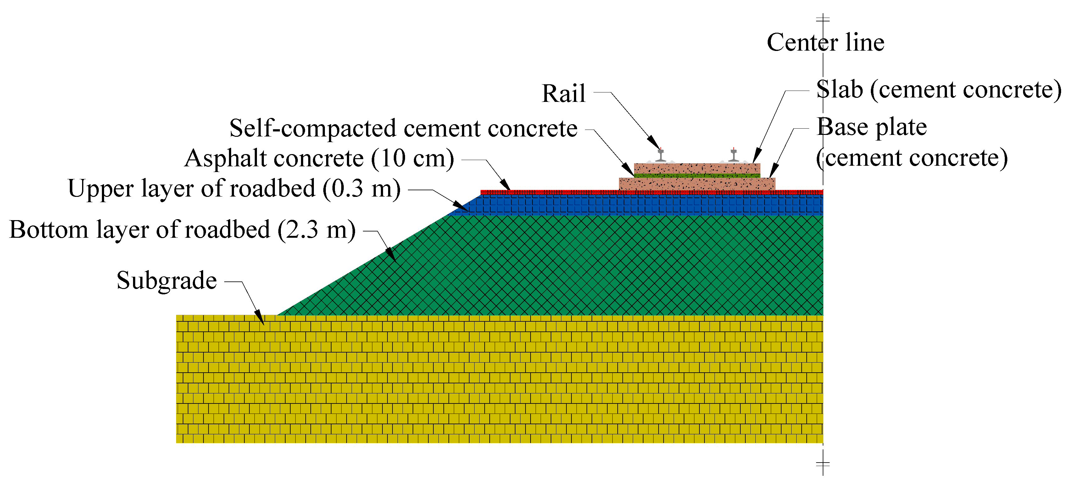
In the ballastless track system of China’s high-speed railway with an asphalt concrete substructure, the infrastructures under the rail are sequentially the track plate, base plate, asphalt concrete, upper layer of the roadbed, bottom layer of the roadbed, and subgrade from top to bottom. It is similar to the highway pavement structure and can be regarded as a multi-layer system. As is known to all, the asphalt concrete surface layer in the highway directly subjects to the vehicle load, and tensile strains will be generated at the bottom of the asphalt concrete, thus causing fatigue cracking damage to the asphalt pavement. Similarly, related studies show that tensile strains will be also generated at the bottom of the asphalt concrete substructure under the action of the train load [18]. Obviously, it is not difficult to predict that fatigue cracking damage will also be one of the failure modes of asphalt concrete under the cyclic train load. Therefore, the tensile strain at the bottom of the asphalt concrete substructure can be used as an important basis for material and structural designs, and is a key parameter for the study of the structural mechanical characteristics. It will be considered in our test design.
2.2. Effect of the Temperature
Periodic changes in the ambient air temperature will affect the thermal field inside the asphalt concrete substructure to change periodically within one year or one day. Self-restraint tensile stress or even low-temperature cracking will be generated due to the negative temperature gradient and volume shrinkage [22]. In addition, due to fact that the size of the asphalt concrete paved in the railway is much larger in the longitudinal direction than that in the transverse direction, the transverse self-restraint stress will not be too large. Therefore, low-temperature cracking of the asphalt concrete will occur along the longitudinal direction intermittently.
Besides, the reduction in the ambient air temperature will also cause the shrinkage of the cement concrete base plate. Moreover, the base plate is bonded with the asphalt concrete layer and the expansion joint of the base plate is at a stress concentration position. Therefore, the deformation of the base plate will drive the asphalt concrete substructure to generate passive tension and even local cracking damage, resulting in transverse cracks near the expansion joint [22].
To sum up, considering the position and working conditions of the asphalt concrete substructure under the rail track, it may suffer from the following damage types: fatigue cracking, low-temperature cracking and passive tensile cracking near the expansion joint of the base plate. This paper will investigate the mechanical characteristics of asphalt concrete for a ballastless track substructure under the action of the cyclic train load and ambient temperature through field tests of the asphalt concrete test section, and reveal the potential failure modes of the asphalt concrete.
3. Test Section of Asphalt Concrete for Ballastless Track Substructure
Based on a high-speed railway ballastless track project in north China, a test section of a full-section asphalt concrete paved between the base plate and the surface of the roadbed was constructed. In situ forced vibration and temperature-induced deformation monitoring tests were performed to investigate the mechanical responses of the asphalt concrete substructure, respectively. In this section, the design and construction of the asphalt concrete test section as well as the test program and arrangement of sensors will be described.
3.1. Overview of the Test Section
This test section of the asphalt concrete substructure was located in Zhangjiakou city, Hebei province. The total length was 420 m from DK143 + 450 to DK143 + 870. In this test section, the roller-compacted asphalt concrete with a thickness of 10 cm was paved on the surface of the roadbed, as shown in Figure 1. The test section was constructed in October 2017.
3.2. Design of the Asphalt Concrete
According to the above analysis of the working conditions of the asphalt concrete for the high-speed railway substructure, asphalt concrete materials should have a good waterproofing performance, bearing capacity, low-temperature cracking resistance, water damage resistance, and fatigue resistance. Therefore, in the design process of the asphalt concrete for this project, many factors such as the selection of the asphalt binders and aggregates and the gradation optimization method had been taken into account comprehensively. Moreover, the dense gradation asphalt concrete AC-16, with the nominal maximum aggregate size of 16 mm, was selected as the design target, and the construction method of hot mixing and hot paving was adopted to achieve the above functionalities.
Finally, a performance grade of a PG 76-28 SBS (styrene-butadiene-styrene) + TPS (tough polystyrene)-modified asphalt binder provided by Jiangsu Baoli International Investment Co., Ltd. (Jiangyin, China) was selected. The basic properties of this composite modified asphalt binder are shown in Table 1, based on Chinese test protocols [23]. The aggregates were provided by the China Academy Railway Institute (Beijing, China). The final mixture gradation is shown in Figure 2. The volume parameters and stability and flow values of the Marshall specimens with different asphalt–aggregate ratios (4.0%, 4.5%, 5.0%, 5.5%, and 6.0%) were measured, and the test results are shown in Table 2. According to the Chinese technical specifications [24], the optimum asphalt–aggregate ratio was determined as 5.1%.
3.3. Performance Evaluation of the Asphalt Concrete
A variety of laboratory tests according to the “Standard Test Methods of Bitumen and Bituminous Mixtures for Highway Engineering” [23] were adopted to evaluate the bearing capacity, waterproofing performance and the durability of the designed asphalt concrete for a ballastless track substructure, including a infiltration test, wheel tracking test, indirect tension test, four-point bending beam test, low temperature bending beam test, and dynamic modulus test. Figure 3 shows some test samples and procedures. Table 3 shows the test results. It can be seen that the performance parameters of the designed asphalt concrete can fully meet the technical requirements. It has a good waterproofing property and an excellent load-bearing performance to satisfy the functional requirements during its service life. Therefore, the designed asphalt concrete is suitable for the real practice.
3.4. Construction Process of the Asphalt Concrete
The asphalt concrete for a ballastless track substructure was constructed following the overall procedure flow shown in Figure 4. First, check and clean the surface of the upper layer of the roadbed to ensure that there is no excess graded crushed stone scum, which is not conducive to the integrity of the structure. Secondly, spread and maintain the emulsified asphalt, and measure the spreading amount of the emulsified asphalt in the process to ensure the design requirement. Then, produce the asphalt concrete in the mixing station, transport the asphalt concrete to the construction site, and pave the asphalt concrete by spreading machines. After that, compact the asphalt concrete. Finally, maintain the asphalt concrete and conduct post-construction inspections.
3.5. Test Program and Arrangement of Sensors
The in situ tests consisted of two parts. The first one was the forced vibration test, which was used to investigate the dynamic responses of the asphalt concrete substructure induced by the cyclic high-speed train load. The second part was the temperature-induced deformation monitoring test, which was mainly to study the thermodynamic properties of the asphalt concrete substructure caused by changes in the ambient air temperature.
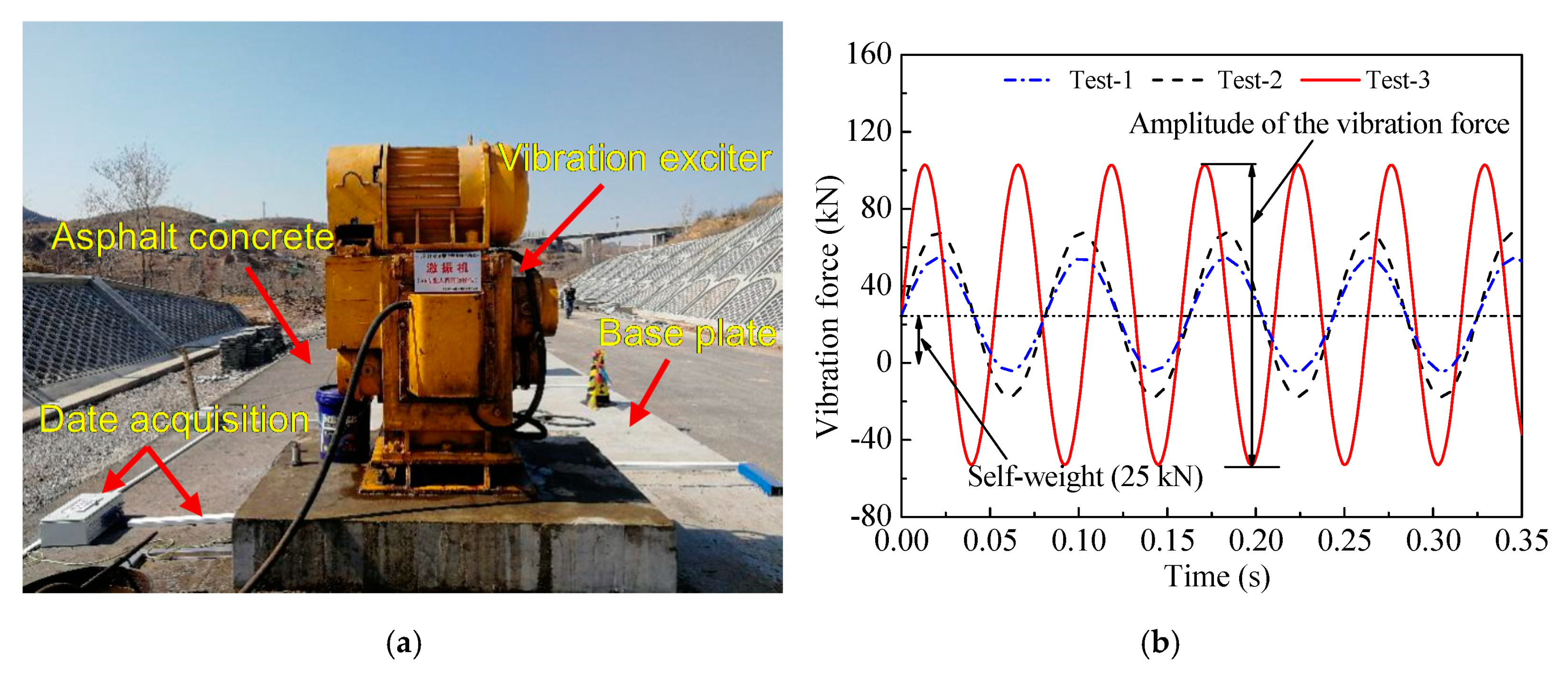
For the in situ forced vibration test, the vibration exciter SBZ30 with the sinusoidal loading form, as shown in Figure 5, was selected to simulate the cyclic train load in the asphalt concrete substructure test section from January to April 2018. According to the design parameters of the high-speed train such as the axle weight, the axle distance, and the running speed, the forced vibration tests were designed into three groups. The specific parameters of the vibration exciter for each group are shown in Table 4. The tests were conducted at the frequency of 12.3 Hz with the vibration force amplitude of 58.8 kN, at the frequency of 12.3 Hz with the vibration force amplitude of 105.2 kN, and at the frequency of 19.0 Hz with the vibration force amplitude of 155.8 kN in test-1, test-2, and test-3, respectively. They were equivalent to the actual train load with the speed of 350 km/h and the axle load of 17 tons, the speed of 350 km/h and the axle load of 19 tons, and the speed of 450 km/h and the axle load of 19 tons, respectively. The number of loading cycles in each test was two million.
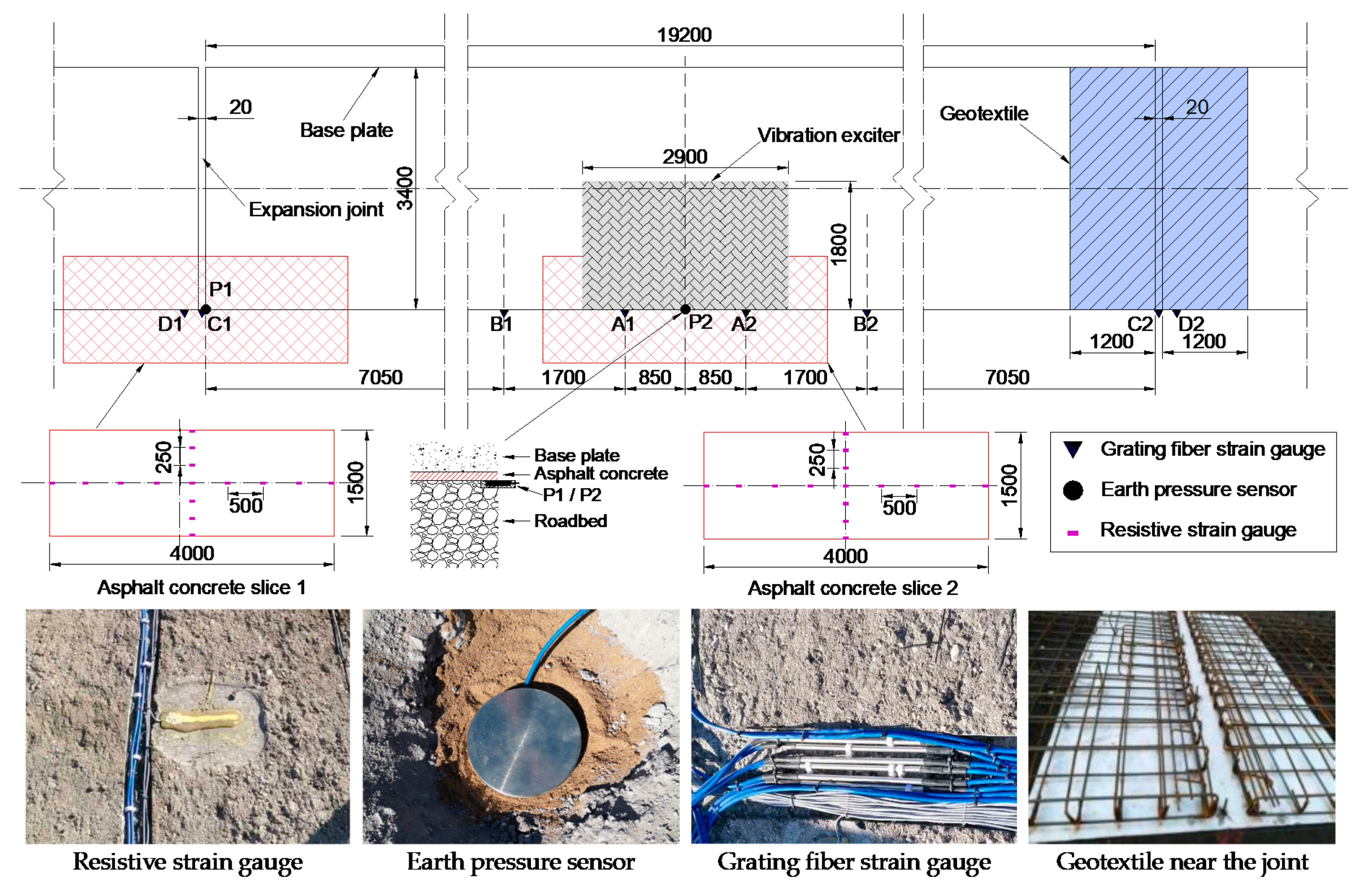
For the temperature-induced deformation monitoring test, the field ambient air temperature and the thermal strains of the asphalt concrete caused by changes in the temperature were monitored continuously from March 4 to March 6 2018. In addition, according to the above analysis of the working conditions of the asphalt concrete substructure, the expansion and contraction of the base plate will also cause the coordination deformation of the asphalt concrete substructure. However, the coordinating effect of the base plate and the asphalt concrete substructure can be reduced, if the inter-layer bonding between them is weakened. Therefore, a comparison structure has been constructed in the test section. That is, the geotextile has been set with a width of 1.2 m at both the left and right ends of the expansion joint, as shown in Figure 6, to isolate and weaken the inter-layer bonding effect.
The forced vibration test focuses on the tensile strain at the bottom of the asphalt concrete layer and the compressive stress on the surface of the roadbed. The temperature-induced deformation monitoring test focuses on the thermal strain characteristics on the surface of the asphalt concrete, especially the mechanical and thermodynamic behavior of the asphalt concrete substructure near the center of the base plate and the expansion joints. Therefore, the arrangement of sensors in this test is shown in Figure 6, including 2 earth pressure sensors (denoted by P1 and P2), 8 grating fiber strain gauges (denoted by A1, A2, B1, B2, C1, C2, D1, and D2), and 30 resistive strain gauges. More specifically, the earth pressure sensors were set at the depth of 10 cm below the surface of the roadbed, corresponding to the plane position at the center of the asphalt concrete slice 1 and slice 2. The space around the pressure sensors was backfilled with fine sand after the placement, as shown in Figure 6. The grating fiber strain gauges were arranged on the surface of the asphalt concrete. The resistance strain gauges were uniformly pasted on the bottom of the asphalt concrete slices. The adhesive was CC-33A, and a 2 mm thick epoxy coating was used to protect the strain gauges, as shown in Figure 6. The arrangement process was as follows:
- (1)
- Cut and lift the asphalt concrete slice 1 and slice 2;
- (2)
- Locate the adhesive position of the strain gauges and polish the surface;
- (3)
- Stick the strain gauges;
- (4)
- Connect the wires and construct the bridge;
- (5)
- Coat the strain gauges with the epoxy for protection;
- (6)
- Put the asphalt concrete slices back to the original position;
- (7)
- Use rivets to connect the slices with the surrounding asphalt concrete into an integral structure.
4. Monitoring Result of Asphalt Concrete in the Test
In this section, in-site test results are presented and analyzed. The mechanical characteristics and potential failure modes of the asphalt concrete substructure affected by the cyclic train load and the environmental temperature are discussed.
4.1. Responses Induced by the Train Load
Figure 7 shows the measured accumulative strains at the bottom of the asphalt concrete substructure and the earth pressure on the surface of the roadbed in the forced vibration tests. The results are positive, indicating that the bottom of the asphalt concrete layer is in the tensile state and the surface of the roadbed is in the compressive state under the action of the cyclic train load. Meanwhile, the tensile strains and the earth pressure near the expansion joint of the base plate are larger than those near the middle position of the base plate. More specifically, for the asphalt concrete slice 1 (near the expansion joint), the maximum earth pressure on the surface of the roadbed is 40 kPa, 55 kPa, and 76 kPa in test-1, test-2, and test-3, respectively. The maximum tensile strains at the bottom of the asphalt concrete layer are 29 με, 47 με, and 85 με in test-1, test-2, and test-3, respectively. Meanwhile, for slice 2 (near the middle position), the maximum earth pressure is 30 kPa, 50 kPa, and 64 kPa and the maximum tensile strains are 23 με, 35 με, and 57 με in test-1, test-2, and test-3, respectively.
As is known to all, under normal conditions, the vibration of the base plate and the vertical pressure should be more obvious near the vibration exciter. However, the expansion joints are weak points in the whole ballastless track system. It may result in different vibration characteristics of the base plate near the expansion joint, which may lead to greater vertical earth pressure in this place. However, the vibration mechanism is unclear currently. Further studies about this are required based on the relevant vibration theory.
Besides, with the increase in the vibration frequency and the amplitude of the vibration force (actually, the train speed and axle load), the strain and the earth pressure increase, and the growth rate near the expansion joint is mostly larger than that near the middle of the base plate.
4.2. Responses Induced by the Temperature
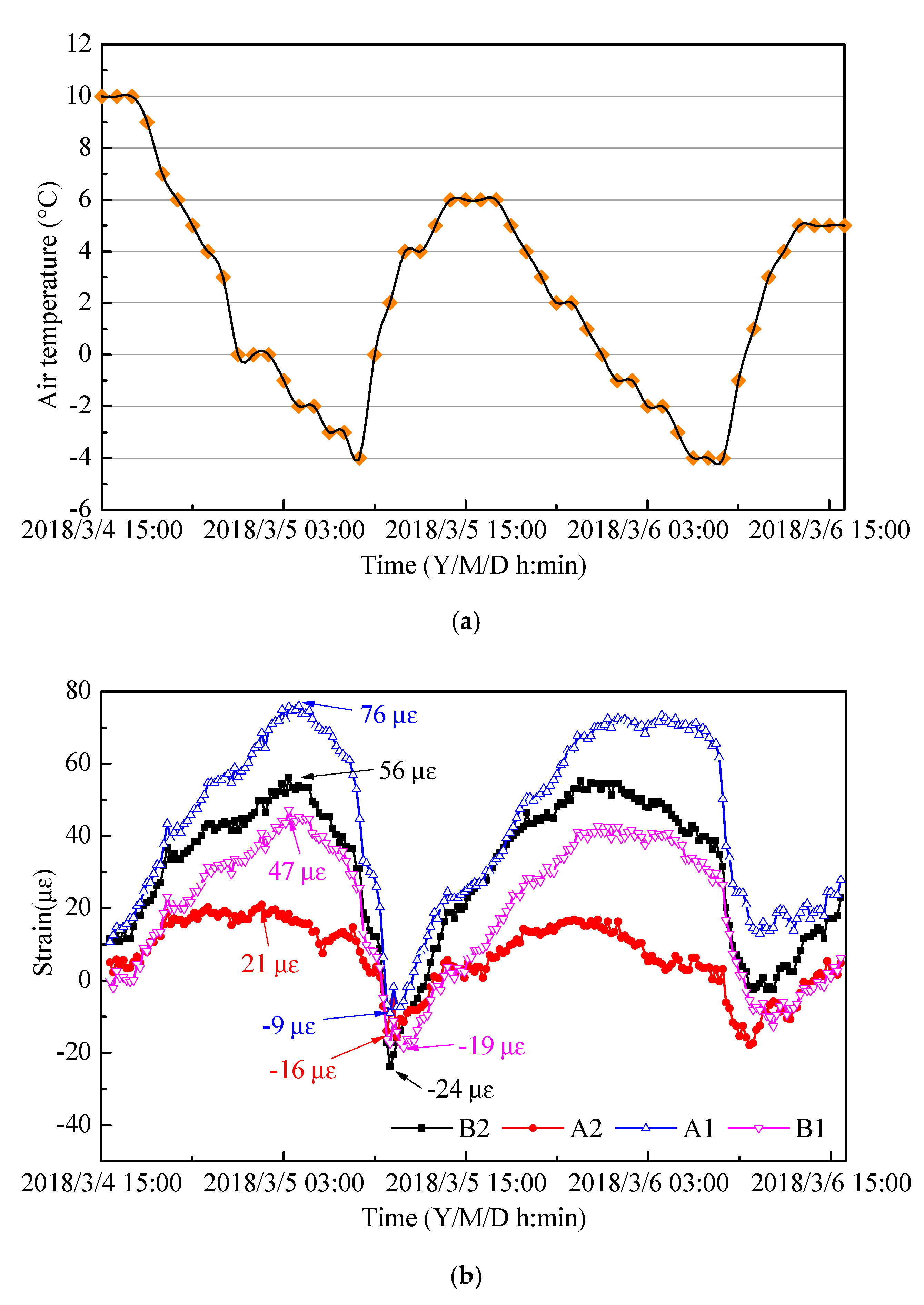
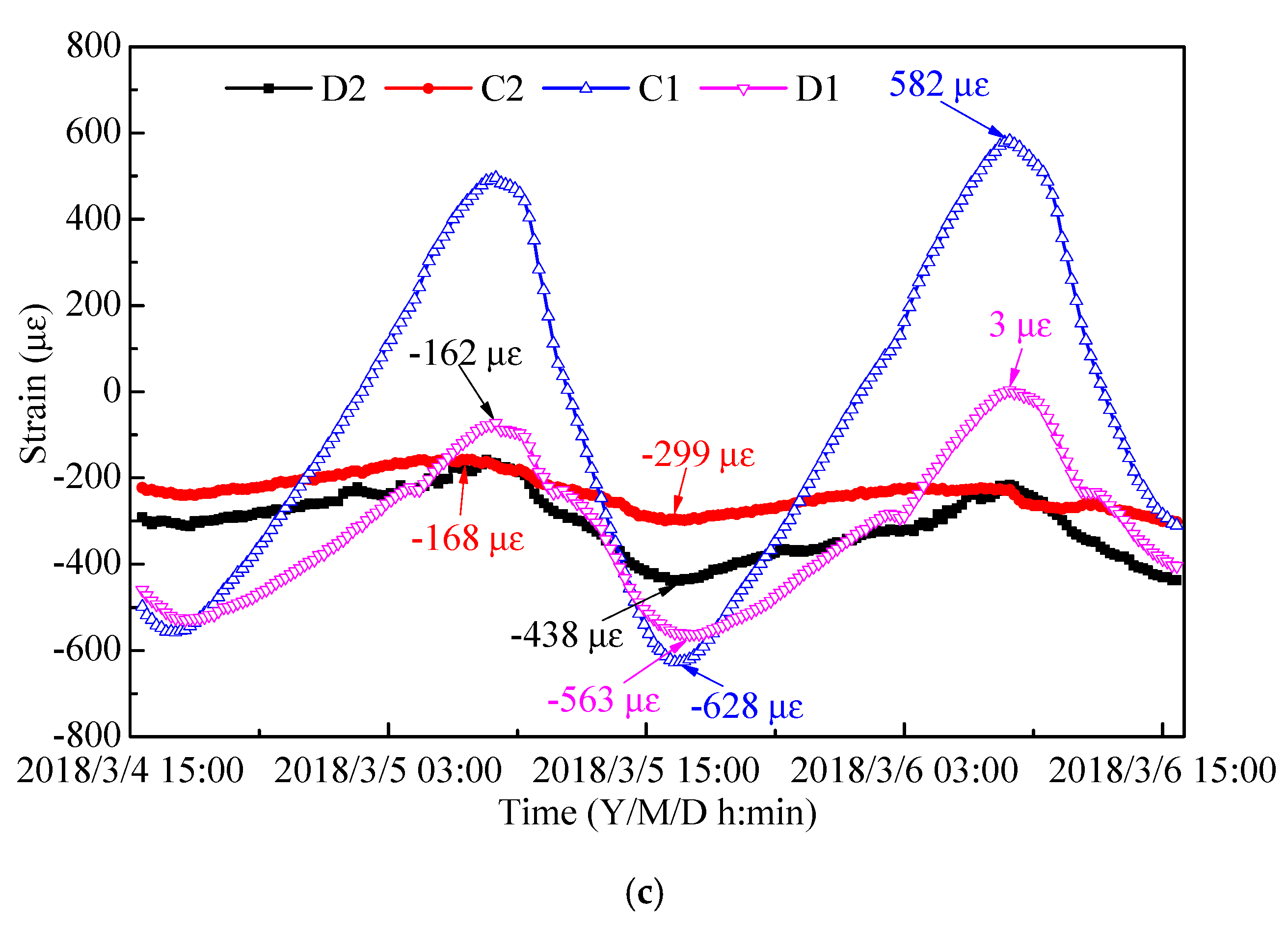
Figure 8 shows the time history curves of the ambient air temperature, the temperature-induced strain in the middle of the base plate, and the temperature-induced strain near the expansion joint, respectively. In general, the strain of the asphalt concrete layer caused by the diurnal variation of the ambient temperature is positive for most of the time near the middle position of the base plate, indicating that the surface of the asphalt concrete is in a tensile state, while it changes alternately between positive and negative values near the expansion joint, indicating that the surface is in the state of alternating tension and compression. This is because the diurnal variation of the temperature leads to the alternate changes in the temperature gradient inside the base plate and asphalt concrete substructure. When the temperature gradient is positive (the temperature was higher in the top than that in the bottom), the edge of the base plate warps downward and the center is relatively convex. Subsequently, the surface of the asphalt concrete in contact with the base plate is subjected to the compression near the expansion joint and the tension near the middle position of the base plate. Conversely, the state is exactly the opposite when the temperature gradient is negative. Besides, according to the comparison between the results in Figure 7 and Figure 8 above, it can be seen that the mechanical responses caused by the ambient temperature changes are larger than those caused by the train load.
By comparing Figure 7c and Figure 8b, it can be seen that the maximum tensile strain and diurnal variation range of the asphalt concrete near the expansion joint are much larger than those near the middle of the base plate. For example, the maximum tensile strains monitored by the grating fiber strain gauges A1 (near the middle position) and C1 (near the expansion joint) are 76 με and 582 με, respectively. Further, the variation ranges are 86 με and 1210 με, respectively. Therefore, the asphalt concrete near the expansion joint is more significantly affected by changes in the ambient temperature, which need to have careful attention paid to them.
To study the coordinating deformation effect of the base plate and the asphalt concrete substructure, a comparison structure with the geotextile set at the end of an expansion joint has been constructed. Grating fiber strain gauges C1 and D1 were mounted near the expansion joint without the geotextile, and C2 and D2 were mounted near the expansion joint with the geotextile. According to the results shown in Figure 8c, the maximum strains obtained by C1, D1, C2, and D2 are 582 με, 3 με, −168 με, and −162 με, respectively. The minimum values are −628 με, −563 με, −299 με, and −438 με, respectively. The daily variation ranges are 1210 με, 566 με, 131 με, and 276 με, respectively. It can be concluded that the isolation layer, such as the geotextile, can significantly reduce the strain level near the expansion joint, which has a positive effect on resisting the passive tensile failure induced by the base plate.
5. Investigation and Failure Mode Analysis of Asphalt Concrete
In June 2018, the forced vibration exciter and the base plate were removed to better investigate the service status of the asphalt concrete for a ballastless track substructure after long-term forced vibration and temperature-induced deformation monitoring tests. Some useful findings are as follows:
- (1)
- In general, the asphalt concrete layer in the test section is in good service condition. There are only a few inconspicuous cracks in some locations, which may be caused by the removal of the base plate. Further, these cracks basically have no impact on the later service of the asphalt concrete;
- (2)
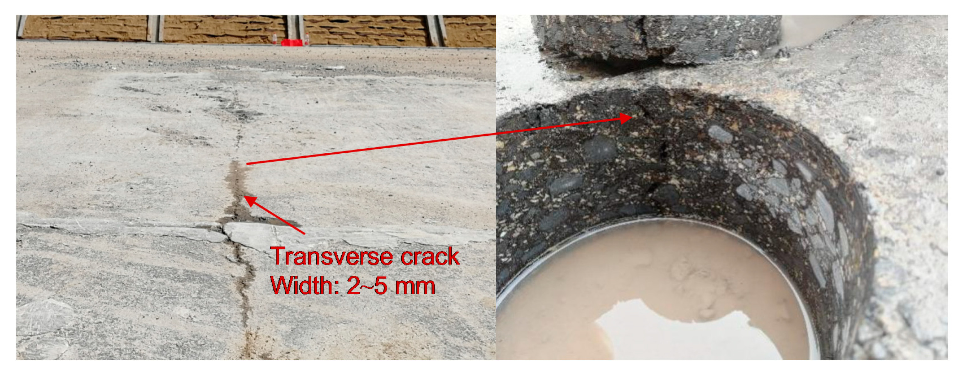
- There is a transverse crack with the width of 2~4 mm in the expansion joint of the base plate without the geotextile, as shown in Figure 9. Through the core sample at the crack location, it is found that the crack runs through the entire asphalt concrete layer, which will seriously affect the service performance, while no such cracks have been found in the expansion joint of the base plate with the geotextile;
- (3)
- It can be concluded that the cracks in the asphalt concrete in the expansion joints caused by the temperature-induced deformation of the base plate are the main failure mode of the asphalt concrete for the ballastless track substructure. By setting the isolation layer, mechanical responses near expansion joints can be effectively reduced, which is useful for resisting the potential passive tensile cracks of the asphalt concrete.
6. Conclusions and Discussion
To investigate the mechanical characteristics and failure mode of the asphalt concrete substructure induced by the cyclic train load and ambient temperature changes, in situ forced vibration and temperature-induced deformation monitoring tests were performed based on a high-speed railway ballastless track project in north China. The main conclusions can be summarized as follows:
- The bottom of the asphalt concrete layer is in the tensile state and the surface of the roadbed is in the compressive state under the action of cyclic train load. The surface of the asphalt concrete near the expansion joint is subjected to tensile stress under the action of the negative temperature gradient, which may cause potential cracks;
- The influence of environmental temperature changes on the mechanical characteristics of the asphalt concrete is greater than that of the cyclic train load. The tensile strain level, the earth pressure, and the diurnal variation range of the asphalt concrete near the expansion joint are also much larger than those near the middle position of the base plate. Therefore, more attention should be paid to the influence of temperature changes in future studies;
- Isolation layers, set under the base plate near the expansion joint, can significantly reduce the mechanical responses near the joint, which has a positive effect on resisting the passive tensile failure induced by the base plate. The geotextile is an effective material for the isolation layer and can be applied to similar railway projects in the future. However, the setting range of this isolation layer needs further studies;
- Besides, in the design and application of the asphalt concrete for the ballastless track substructure, the low-temperature cracking resistance and fatigue resistance should be paid more attention to, and asphalt materials with a good low-temperature and fatigue performance are more suitable, such as crumb rubber-modified asphalt binders.
Author Contributions
The authors confirm contribution to the paper as follows: Methodology: Q.F., X.C., D.C.; data collection: Q.F., L.L.; formal analysis: Q.F.; writing—original draft: Q.F.; writing—review and editing: X.C.; Supervision: X.C., D.C.; funding acquisition: X.C., D.C. All authors have read and agreed to the published version of the manuscript.
Funding
This research was funded by the National Natural Science Foundation of China (grant number 51778136, 41972299) and the Special Scientific Foundation of China Academy of Railway Sciences Co. Ltd. (grant number J2019G003).
Conflicts of Interest
The authors declare no conflict of interest.
Data Availability
All the test data of this study have been included in the article.
References
- D’Angelo, G.; Sol-Sánchez, M.; Navarro, F.M.M.; Presti, D.L.; Thom, N. Use of bitumen-stabilised ballast for improving railway trackbed conventional maintenance. Geotechnique 2018, 68, 518–527. [Google Scholar] [CrossRef]
- Fang, M. Structural behavior and mix design for asphalt concrete substructures in high-speed rail. Ph.D Thesis, Southwest Jiaotong University, Chengdu, China, 2017. [Google Scholar]
- Rose, J.G.; Souleyrette, R.R. Hot-Mix Asphalt (Bituminous) Railway Trackbeds: In-Track Tests, Evaluations, and Performances-a Global Perspective: Part I-Introduction to Asphalt Trackbeds and International Applications and Practices. In Proceedings of the 3rd International Conference on Transportation Infrastructure, Pisa, Italy, 22–25 April 2014; CRC Press: Pisa, Italy, 2014. [Google Scholar]
- Rose, J.G.; Teixeira, P.F.; Veit, P. International Design Practices, Applications, and Performance of Asphalt/Bituminous Railway Trackbeds. In Proceedings of the GEORAIL 2011-International Symposium, Paris, France, 19–20 May 2011. [Google Scholar]
- Chupin, O.; Martin, A.; Piau, J.-M.; Hicher, P.-Y. Calculation of the dynamic response of a viscoelastic railway structure based on a quasi-stationary approach. Int. J. Solids Struct. 2014, 51, 2297–2307. [Google Scholar] [CrossRef] [Green Version]
- Ferreira, T.M.; Teixeira, P.; Cardoso, R. Impact of Bituminous Subballast on Railroad Track Deformation Considering Atmospheric Actions. J. Geotech. Geoenvironmental Eng. 2011, 137, 288–292. [Google Scholar] [CrossRef]
- Sol-Sánchez, M.; Pirozzolo, L.; Navarro, F.M.M.; Rubio-Gamez, M.C. Advanced characterisation of bituminous sub-ballast for its application in railway tracks: The influence of temperature. Constr. Build. Mater. 2015, 101, 338–346. [Google Scholar] [CrossRef]
- Sol-Sánchez, M.; Pirozzolo, L.; Navarro, F.M.M.; Rubio-Gamez, M.C. A study into the mechanical performance of different configurations for the railway track section: A laboratory approach. Eng. Struct. 2016, 119, 13–23. [Google Scholar] [CrossRef]
- Teixeira, P.; Pita, A.L.; Ferreira, P.A. New possibilities to reduce track costs on high-speed lines using a bituminous sub-ballast layer. Int. J. Pavement Eng. 2010, 11, 301–307. [Google Scholar] [CrossRef]
- Lee, S.-H.; Choi, Y.-T.; Lee, H.-M.; Park, D.-W. Performance evaluation of directly fastened asphalt track using a full-scale test. Constr. Build. Mater. 2016, 113, 404–414. [Google Scholar] [CrossRef]
- Momoya, Y.; Sekine, E. Performance-Based Design Method for Raailway Asphalt Roadbed. Doboku Gakkai Ronbunshuu E 2007, 63, 608–619. [Google Scholar] [CrossRef] [Green Version]
- Chen, X.-H.; Tao, T.-Q.; Yang, G.-T.; Yan, H.-Y.; Yang, J. Long-Lasting Waterproofing Solution for the Subgrade of High-Speed Railway in Cold Region. J. Test. Evaluation 2018, 47, 20180046. [Google Scholar] [CrossRef]
- Liu, S.; Yang, J.; Chen, X.; Yang, G.; Cai, D. Application of Mastic Asphalt Waterproofing Layer in High-Speed Railway Track in Cold Regions. Appl. Sci. 2018, 8, 667. [Google Scholar] [CrossRef] [Green Version]
- Fu, Q.; Chen, X.; Cai, D.; Yang, J.; Yang, G. Full-section asphalt concrete waterproof sealing structure for high speed railway subgrade. China Railw. Sci. 2020, 41, 24–33. [Google Scholar] [CrossRef]
- Cardona, D.R.; Di Benedetto, H.; Sauzeat, C.; Calon, N.; Saussine, G. Use of a bituminous mixture layer in high-speed line trackbeds. Constr. Build. Mater. 2016, 125, 398–407. [Google Scholar] [CrossRef]
- Esmaeili, M.; Amiri, S.; Jadidi, K. An investigation into the use of asphalt layers to control stress and strain levels in railway track foundations. Proc. Inst. Mech. Eng. Part F J. Rail Rapid Transit 2012, 228, 182–193. [Google Scholar] [CrossRef]
- Fang, M.; Qiu, Y.; Rose, J.G.; West, R.C.; Ai, C. Comparative analysis on dynamic behavior of two HMA railway substructures. J. Mod. Transp. 2011, 19, 26–34. [Google Scholar] [CrossRef] [Green Version]
- Zhou, J.; Chen, X.; Fu, Q.; Xu, G.; Cai, D. Dynamic Responses of Asphalt Concrete Waterproofing Layer in Ballastless Track. Appl. Sci. 2019, 9, 375. [Google Scholar] [CrossRef] [Green Version]
- Yu, Z.; Connolly, D.; Woodward, P.; Laghrouche, O. Settlement behaviour of hybrid asphalt-ballast railway tracks. Constr. Build. Mater. 2019, 208, 808–817. [Google Scholar] [CrossRef]
- Yang, E.; Wang, K.C.; Qiu, Y.; Luo, Q. Asphalt Concrete for High-Speed Railway Infrastructure and Performance Comparisons. J. Mater. Civ. Eng. 2016, 28, 04015202. [Google Scholar] [CrossRef]
- Yang, E.; Wang, K.C.P.; Luo, Q.; Qiu, Y. Asphalt Concrete Layer to Support Track Slab of High-Speed Railway. Transp. Res. Rec. J. Transp. Res. Board 2015, 2505, 6–14. [Google Scholar] [CrossRef]
- Liang, Y. Study on Low Temperature Response of Asphalt Concrete Structure under CRTS III Type Ballastless; Southeast Univeristy: Nanjing, China, 2019. [Google Scholar]
- Research Institute of Highway Ministry of Transport. Technical Specifications for Construction of Highway Asphalt Pavements; JTG F40-2004; China Communications Press: Beijing, China, 2004. [Google Scholar]
- Research Institute of Highway Ministry of Transport. Standard Test Methods of Bitumen and Bituminous Mixtures for Highway Engineering; JTG E20-2011; China Communications Press: Beijing, China, 2011. [Google Scholar]
Figure 1.
Schematic diagram of the asphalt concrete substructure in the test section.

Figure 2.
Gradation curves of the designed asphalt concrete.
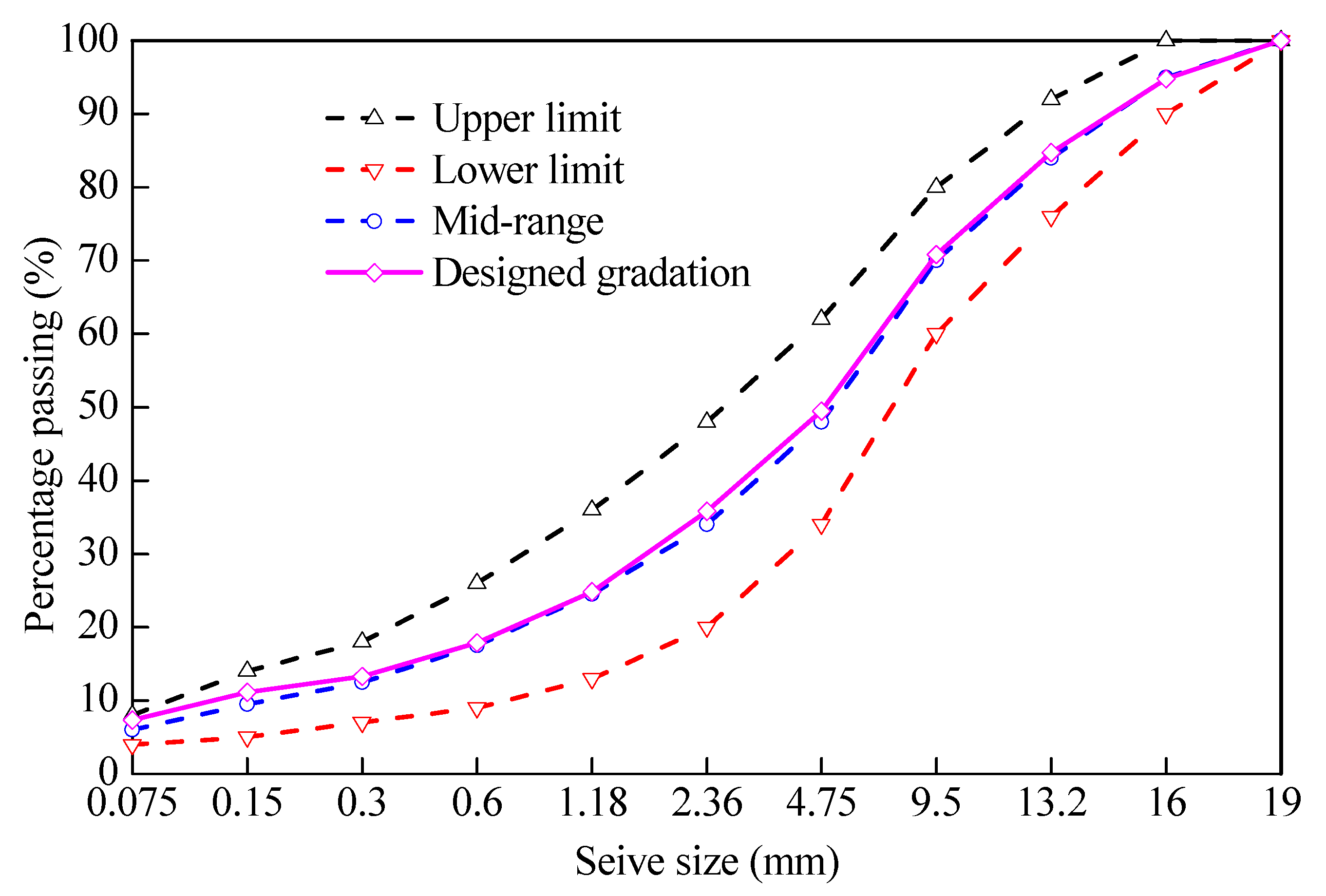
Figure 3.
Some test samples and procedures: (a) infiltration test; (b) wheel tracking test; (c) indirect tensile test; (d) fatigue test; (e) low temperature bending beam test; and (f) dynamic modulus test.
Figure 3.
Some test samples and procedures: (a) infiltration test; (b) wheel tracking test; (c) indirect tensile test; (d) fatigue test; (e) low temperature bending beam test; and (f) dynamic modulus test.
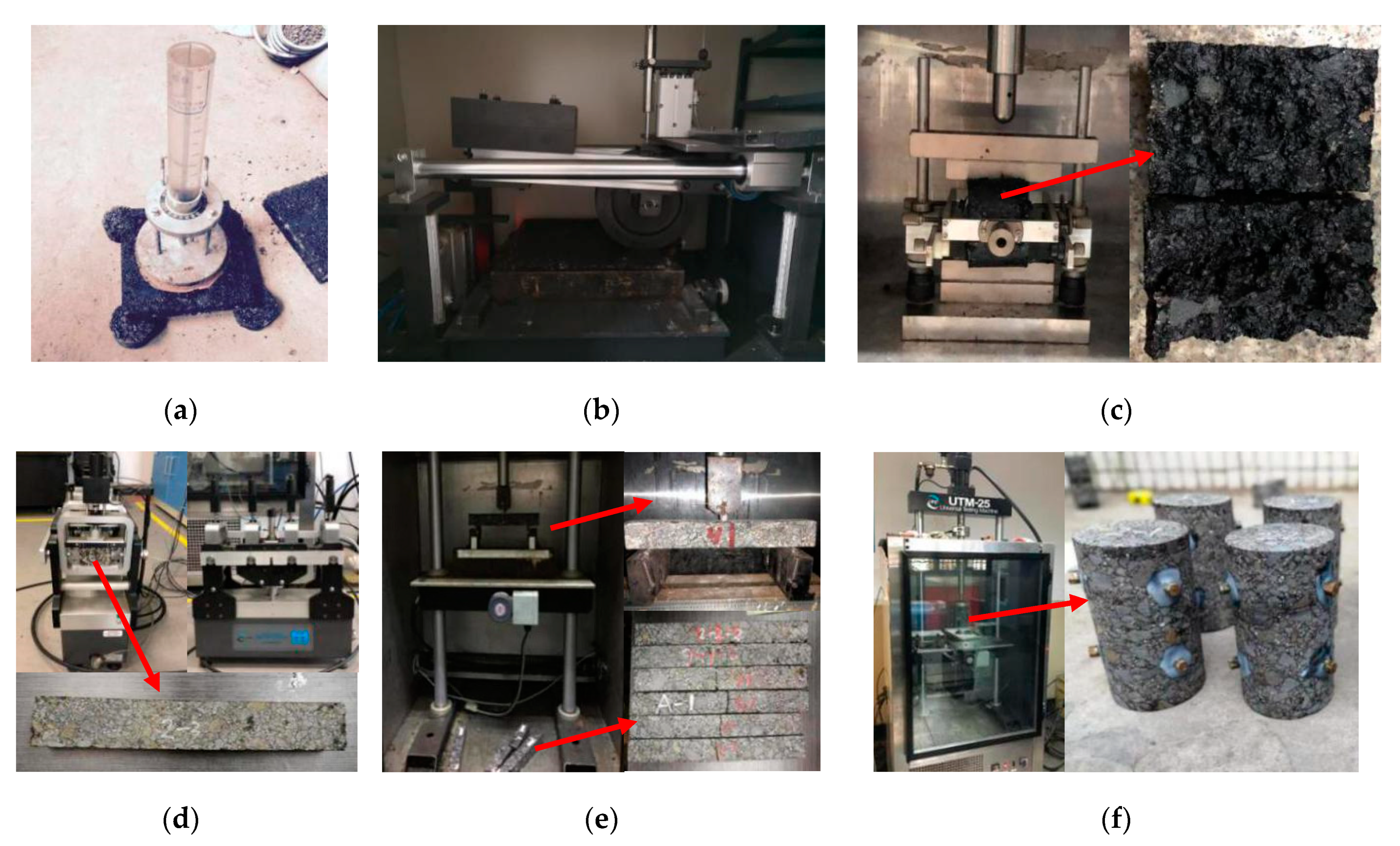
Figure 4.
Construction process of the asphalt concrete in railway.
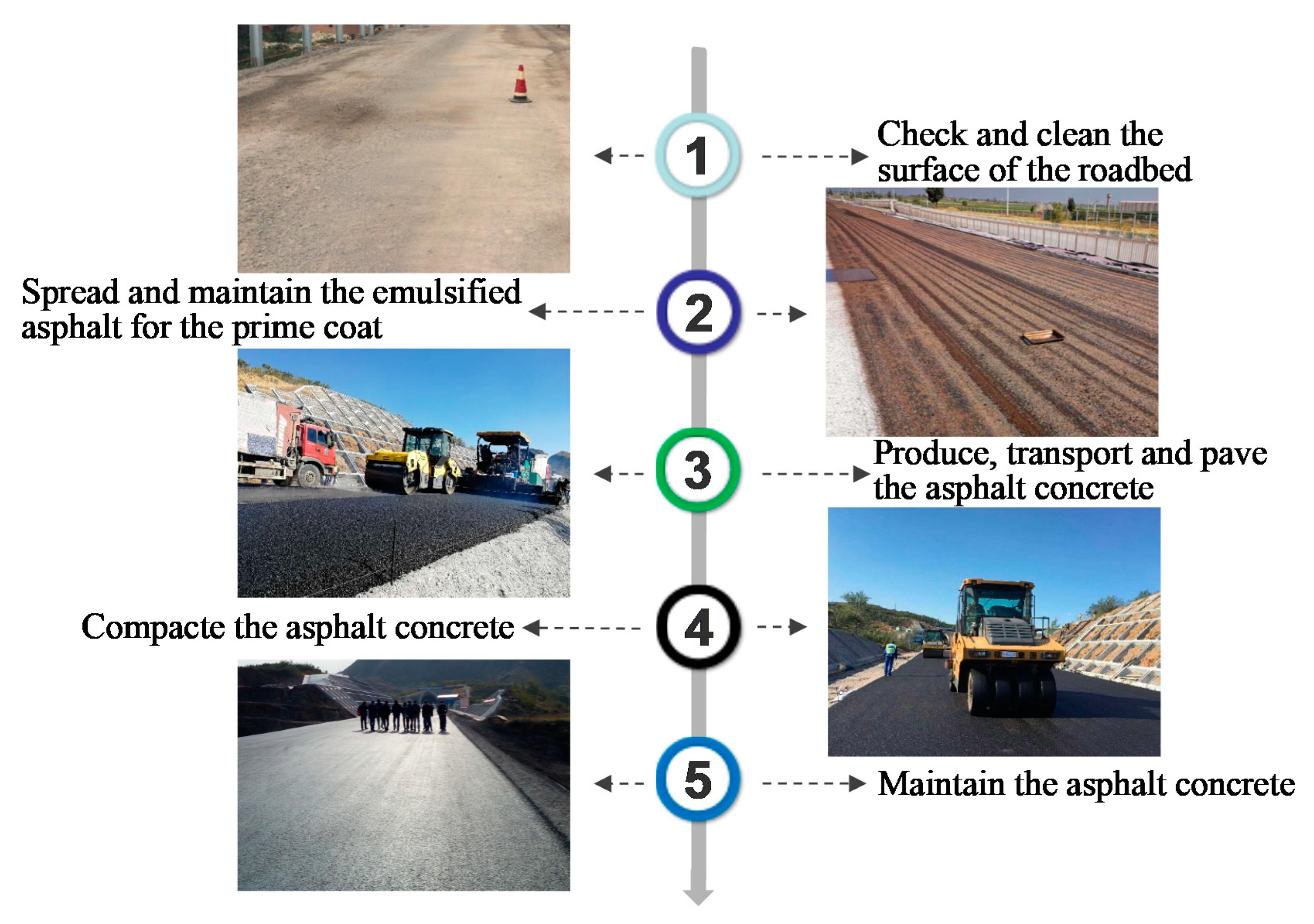
Figure 5.
(a) In situ vibration exciter and (b) the loading form.

Figure 6.
Arrangement of sensors in the test (unit: mm).

Figure 7.
Measured accumulative strains and the earth pressure in the forced vibration tests: (a) maximum value of the earth pressure; (b) average value of the strain; and (c) maximum value of the strain.
Figure 7.
Measured accumulative strains and the earth pressure in the forced vibration tests: (a) maximum value of the earth pressure; (b) average value of the strain; and (c) maximum value of the strain.
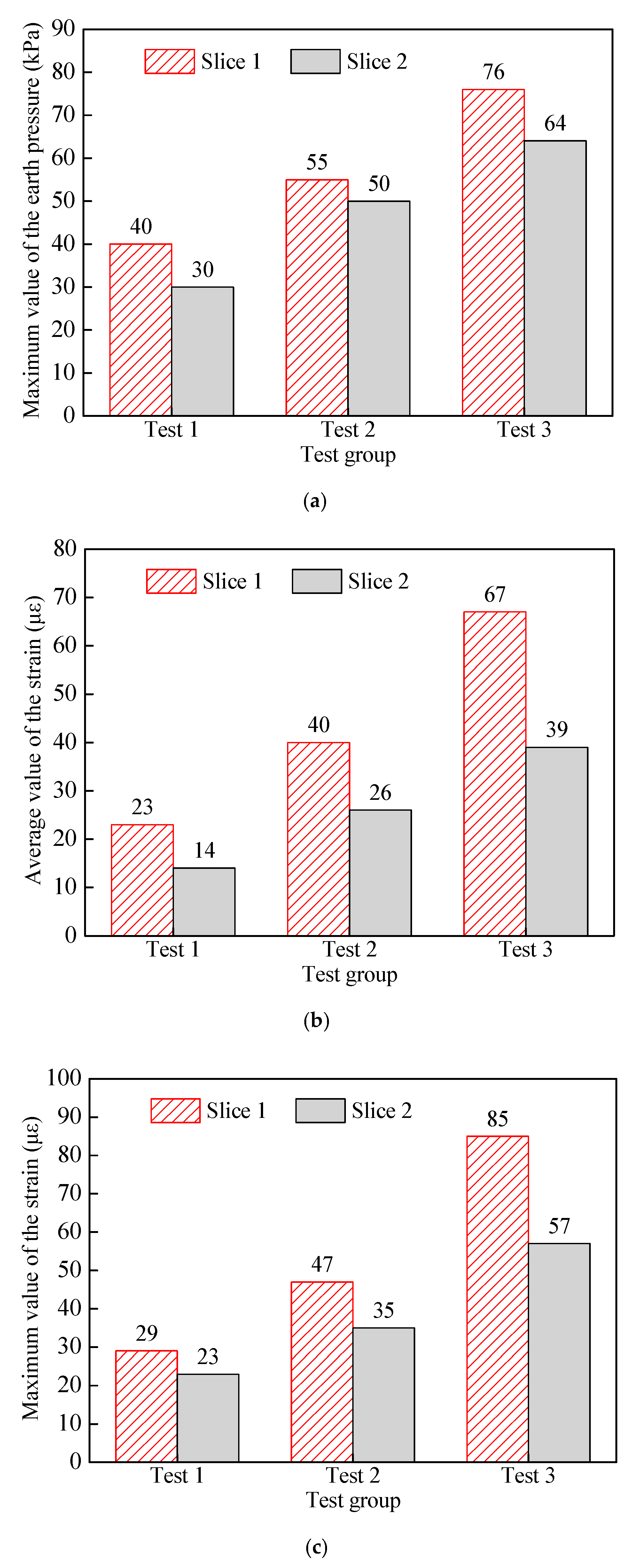
Figure 8.
Time history curves of (a) the air temperature; (b) the induced strain in the middle of the base plate; and (c) the induced strain near the expansion joint.
Figure 8.
Time history curves of (a) the air temperature; (b) the induced strain in the middle of the base plate; and (c) the induced strain near the expansion joint.


Figure 9.
Crack near the expansion joint of the base plate without the geotextile.


Table 1.
Basic properties of the styrene-butadiene-styrene (SBS) + tough polystyrene (TPS)-modified asphalt binder.
Table 1.
Basic properties of the styrene-butadiene-styrene (SBS) + tough polystyrene (TPS)-modified asphalt binder.
| Parameters (Unit) | Test Results | Technical Requirements | Test Methods |
|---|---|---|---|
| Penetration @ 25 °C (0.1 mm) | 72.9 | 60~80 | T 0604 |
| Penetration index | 1.6 | ≥0.5 | T 0604 |
| Ductility @ 5 °C (cm) | 50.1 | ≥30 | T 0605 |
| Softening point (°C) | 90.5 | ≥80 | T 0606 |
| Fraas breaking point (°C) | −28 | ≤−25 | T 0613 |
| Dynamic viscosity @ 175 °C (Pa·s) | 1.12 | ≤1.5 | T 0625 |
| Flash point (°C) | 280 | ≥260 | T 0611 |
Table 2.
Test results of the Marshal samples with different asphalt–aggregate ratios.
| Asphalt– Aggregate Ratio (%) | Bulk Density (g/cm3) | Void Ratio (%) | VMA (%) | VFA (%) | Stability (kN) | Flow Values (dmm) |
|---|---|---|---|---|---|---|
| 4.0 | 2.473 | 7.1 | 14.71 | 51.99 | 14.57 | 3.77 |
| 4.5 | 2.506 | 5.1 | 14.00 | 63.38 | 15.12 | 2.79 |
| 5.0 | 2.530 | 3.5 | 13.57 | 74.33 | 16.23 | 3.66 |
| 5.5 | 2.525 | 3.0 | 14.18 | 78.85 | 14.64 | 4.52 |
| 6.0 | 2.516 | 2.6 | 14.87 | 82.31 | 13.35 | 5.12 |
Table 3.
Laboratory test results and technical requirements of the designed asphalt concrete.
| Functionality | Parameter (Unit) | Test Result | Technical Requirement | Test Method |
|---|---|---|---|---|
| Waterproofing | Water permeability coefficient (mL/min) | 0 | ≤60 | T 0730 |
| Void ratio (%) | 1.67 | ≤4 | T 0711 | |
| Bearing capacity | Compressive strength @ 20 °C (MPa) | 5.37 | ≥4 | T 0713 |
| Dynamic stability @ 60 °C (cycle/mm) | 3060 | ≥2400 | T 0719 | |
| Dynamic modulus @ 10 Hz, 15 °C (MPa) | 8112 | ≥6000 | T 0738 | |
| Low-temperature cracking resistance | Failure stiffness @ −10 °C (MPa) | 13.26 | ≥8 | T 0715 |
| Failure strain (με) | 3356 | ≥3000 | ||
| Water damage resistance | Resilient stability (%) | 95 | ≥85 | T 0709 |
| Tensile strength ratio (%) | 95 | ≥80 | T 0729 | |
| Fatigue resistance | Fatigue life @ 10 Hz, 500 με, 15 °C (×104 cycle) | 122.5 | ≥20 | T 0739 |
Table 4.
Parameters of the forced vibration tests.
| Test Group | Parameters of the Vibration Exciter | Parameters of the Train | |||
|---|---|---|---|---|---|
| Vibration Frequency (Hz) | Amplitude of the Vibration Force (kN) | Loading Cycle (×104) | Train Speed (km/h) | Train Axle Load (ton) | |
| Test-1 | 12.3 | 58.8 | 200 | 350 | 17 |
| Test-2 | 12.3 | 105.2 | 200 | 350 | 19 |
| Test-3 | 19.0 | 155.8 | 200 | 450 | 19 |
© 2020 by the authors. Licensee MDPI, Basel, Switzerland. This article is an open access article distributed under the terms and conditions of the Creative Commons Attribution (CC BY) license (http://creativecommons.org/licenses/by/4.0/).
Share and Cite
MDPI and ACS Style
Fu, Q.; Chen, X.; Cai, D.; Lou, L. Mechanical Characteristics and Failure Mode of Asphalt Concrete for Ballastless Track Substructure Based on In Situ Tests. Appl. Sci. 2020, 10, 3547. https://doi.org/10.3390/app10103547
AMA Style
Fu Q, Chen X, Cai D, Lou L. Mechanical Characteristics and Failure Mode of Asphalt Concrete for Ballastless Track Substructure Based on In Situ Tests. Applied Sciences. 2020; 10(10):3547. https://doi.org/10.3390/app10103547
Chicago/Turabian StyleFu, Qinghong, Xianhua Chen, Degou Cai, and Liangwei Lou. 2020. "Mechanical Characteristics and Failure Mode of Asphalt Concrete for Ballastless Track Substructure Based on In Situ Tests" Applied Sciences 10, no. 10: 3547. https://doi.org/10.3390/app10103547
Note that from the first issue of 2016, this journal uses article numbers instead of page numbers. See further details here.