1. Introduction
Processing of waste into building materials is aimed at addressing social and environmental problems, improving the living conditions of the local residents by creating jobs. In the production of building materials from recycled waste, economic efficiency can be measured as the environmental damage avoided. The use of recycled materials will reduce the need for primary mineral resources; there will be no need for dedicated clay quarries, and disturbance of natural landscapes will be avoided. The proposed materials and processes can be cost-effective since MM waste will be used as the process input, and the cost of the final product will be reduced compared to the conventional technology.
Accumulated stocks of mining and metallurgical (MM) waste in Russia are commensurate with the demand for the building materials industry for mineral raw materials. However, the recycling rate rarely exceeds 10% [
1]. One of the promising directions in waste recycling is processing the waste into construction ceramics—wall, facing, and paving materials.
Recycling industrial and agricultural waste into construction ceramics is of great importance [
2,
3,
4]. Multiple publications examine the feasibility of recycling MM waste into construction ceramics: ore concentration tailings and slag [
5,
6,
7,
8,
9,
10,
11,
12,
13,
14]. For example, a method for producing high-quality construction ceramics from a composition based on a mixture of tailings of three different industrial sites in Murmansk Region, Russia’s major mining region, is shown in [
6,
12]. The region is experiencing growing problems caused by the accumulation of mining waste, such as copper–nickel ore concentration tailings and slag (JSC Kola MMC), apatite ore concentration tailings (JSC Apatit), and iron quartzite concentration tailings (JSC Olkon).
Granular copper–nickel slag dumps at Pechenganickel smelter (JSC Kola MMC) contain roughly 50 million tons of mineral feedstock. The predominant size of granules is −3 + 0.5 mm. The slag is mostly composed of magnesia-ferruginous olivine glass containing 1–2% of crystalline olivine, as well as finely disseminated magnesioferrite (magnetite) and sulfides.
The total stock of apatite–nepheline ore concentration tailings (ANT) at JSC Apatit is currently more than 750 million tons [
15]. The tailings constitute medium-grained sand measuring −0.5 mm. The primary mineral in the apatite–nepheline ore concentration tailings is nepheline and its secondary minerals (up to 60%). The tailings also contain aegirine, feldspars, titanite, and titanomagnetite.
Ferruginous quartzite concentration tailings (FQT) at JSC Olkon (~300 million tons) mainly consist of quartz (SiO2 content ranges from 60% to 75%), feldspars, amphiboles, pyroxenes, and mica. The tailings constitute coarse-grained sand measuring −1.25 mm.
The goal of this study is to examine the possibility of using copper-nickel slag (CNS) from JSCKola MMC as a component of a multicomponent charge in the production of construction ceramics. Concentration tailings of apatite-nepheline ores from JSC Apatit and concentration tailings of ferruginous quartzites from JSC Olkon were used as other components of the charge.
One of the areas of nickel slag recycling is the production of different building supplies. Thus, [
16] examined the possibility of utilizing the slag for the production of glass-ceramics. Reference [
17] focused on the utilization of nickel slag as a raw material in the production of Portland cement for road construction. Geopolymer prepared with high-magnesium nickel slag was obtained [
18]. The influence of nickel slag powders properties of magnesium potassium phosphate cement paste was examined [
19].
The aim of our research is to provide reasoning for obtaining environmentally friendly ceramic building materials with improved qualities, which are made exclusively of tailings and slag waste without using traditional raw material—clay.
To achieve high strength and frost resistance, low water absorption, and good architectural qualities of the samples, we examined the effect of molding pressure and firing temperature on the phase composition and main properties of the resulting ceramic materials. Special attention was given to increasing the frost resistance of obtained materials.
Traditional semi-dry forming processes for ceramics containing clay often do not allow to achieve high frost resistance, which is one of the primary requirements to ceramic wall and paving materials used in the climatic conditions of Russia. This process challenge is exacerbated when using stiff feedstocks, such as tailings and smelter slag. This can be explained by the formation of a porous structure when the material is molded, with almost all pores open to the atmosphere. When the water-saturated material freezes in a closed environment, the pressure of tens of MPa develops. This problem can be solved by applying protective waterproof or water-repellent coatings to the surface (hydrophobization), forming a structure with a moderate porosity and a sufficient share of closed pores (a matrix structure), and by other process methods [
12,
20,
21].
2. Experimental Procedure
2.1. Raw Materials
The chemical composition of the ceramic charge components is shown in
Table 1.
None of those types of waste individually meet the requirements of obtaining ceramic building supplies from raw materials. Besides the non-plasticity of each type of waste, the high melting points of olivine in CNS, nepheline in ANT, and quartz in FQT, which are predominant in these minerals, are to be noted. The formation of new mineral phases is possible in admixture of components in certain proportions. For example, the interaction of nepheline and quartz leads to the formation of feldspars, which are known as flux in ceramic technology. The addition of calcium oxides and iron oxides to the mixture also contributes to the decreasing of melting point temperature.
However, using three different types of waste, we significantly increased the challenge of predicting the properties of the final product due to multiple mutual effects of involved components appearing upon heating of the mixture. Therefore, the preliminary testing of the following three compositions was conducted: 60% CNS, 20% ANT, and 20% FQT; 50% CNS, 30% ANT, and 20% FQT; 40% CNS, 40% ANT, and 20% FQT. It is determined that the third composition is characterized by the best levels of compressive strength and resistance to bending. An optimal mix containing 40% CNS, 40% ANT, and 20% FQT was used as the initial material to produce ceramic samples.
2.2. Methods
The following methods were used to determine the chemical composition of the ceramic mixture components. SiO2 content and loss on ignition were determined gravimetrically. FeO content was measured by titration. The content of Al2O3, Fe2O3, CaO, MgO, MnO, NiO, CuO, SrO was determined by atomic absorption spectrometry using the KVANT 2A spectrometer (Moscow, Russia). The content of Na2O and K2O was measured by atomic emission spectrometry using the AAnalyst 400 spectrometer (“PerkinElmer Inc.”, Massachusetts, USA). The content of P2O5 and TiO2 was measured by spectrophotometry using the LEKI SS 2107 UV spectrophotometer (“MEDIORA OY”, Finland). The content of CO2 and SO3 was determined by IR spectrometry using the ELTRA CS 2000 analyzer (ELTRA GmbH, Haan, Germany).
Powder X-ray diffraction (XRD) patterns of samples were recorded from 4° to 65° (2θ) on an XRD-6000 Shimadzu diffractometer (Shimadzu Corp, Kyoto, Japan) using CuKα radiation. All the main phases that we found in the ceramic samples were identified using the standard comparison procedure with the Powder Diffraction File (PDF) from the International Centre for Diffraction Data (ICDD). Microscopic analyses of the polished thin sections were performed using the Axioplan-2 imaging microscope (Carl Zeiss AG, Oberkochen, Germany).
2.3. Preparation of Ceramic Samples
The dimensions, shape, and manufacturing method of ceramic samples are similar to those described in [
12].
Ceramic samples were prepared using a semi-dry pressing process. Before processing, the raw materials were dried to constant weight at a temperature of 105 ± 5 °C and dry ground in a ball mill with the collection of the particle size fraction finer than 0.1 mm. The components were thoroughly mixed at a predetermined ratio to a homogeneous state.
To achieve a consistency suitable for molding, 8–12% of water was added to the resulting dry mixture with the addition of 0.5 wt% of sulfite waste liquor to promote raw sample strength. The addition of sulfite waste liquor is applied when pressing the samples made of low-flexible raw material [
6,
10,
12].
Cylindrical samples with a diameter and height of 20 ± 2 mm and in the form of 50 × 50 × (5−7) mm tiles were molded from the prepared ceramic mass using a semi-dry process. The samples were pressed using a hydraulic press with the one-sided application of load at a specific pressure of 20, 50, and 100 MPa. The cylinder sample mass was 17–18 g, tile sample mass was 23–25 g. After pressing, the samples were dried to constant weight in an oven at a temperature of 105 ± 5 °C, then fired in a Nabertherm L9/S laboratory furnace at a temperature of 900, 950, 1000, 1050, and 1100 °C. The average rate of temperature rise was 3.5–4.5 °C/min. Upon reaching the required temperature, the samples were held in the furnace for 1 h. Then, the samples were cooled in the furnace to 500 °C at a rate of 2–3.5 °C and until completely cooled in the furnace for 8 h.
Two methods of increasing frost resistance were used.
The first method was to treat the samples with a hydrophobizingpolyorganosiloxane composition [
22]. The water repellent was applied with a brush to the surface of the fired sample, or the sample was dipped into the water repellent. After drying, the samples were tested for frost resistance.
As for the second method, frost resistance was improved through the formation of the matrix structure in the ceramic building materials by using agglomeration processes (aggregation and granulation) as part of the feed preparation process.
The process used to produce granular molding powders was as follows. Loose wet feed was loaded into the bowl of the mixer-granulator TL-020, and the granulation process started. At a mixing rotor speed of 2850 rpm, a liquid binder (water) was injected through a pneumatic manual sprayer to achieve the optimal moisture content for molding. When the granules were larger enough, the material was unloaded. The granulation time was about 5 min. If larger granules were needed, alternating dusting and wetting of the granules were used. Samples were obtained from granular molding powders by compression molding to measure frost resistance.
2.4. Testing of Ceramic Samples
In fired samples, density, shrinkage, compressive and bending strength, and water absorption were measured by Russian-standard methods for building ceramics [
23,
24,
25], and in some samples, frost resistance was also measured.
Bulk density (ρ, g/cm
3) is the ratio of the sample’s mass to its volume. The arithmetic average of the bulk density measurements of all samples rounded to 0.01 g/cm
3, was adopted as the density value [
24].
Since the source materials are considered to have low plasticity, their air shrinkage of ceramic products during drying is zero. Therefore full shrinkage (Δl, %) will be equal to fire shrinkage, which was determined by measuring the samples before and after heat treatment.
Ceramic products were tested for compressive and bending strength using a PGM-100MG hydraulic press.
Ultimate compressive strength (R
comp, MPa) is the maximum compressive stress that a sample can withstand until it fractures. For this test, the samples were cylinder-shaped, with the cylinder diameter approximately equal to the cylinder height (20 ± 2 mm) [
23].
Ultimate bending strength (R
bend, MPa) is the maximum bending stress that a sample can withstand until it fractures. For these tests, tile-shaped samples measuring 50 × 50 × (5–7) mm placed in a metal mold were used [
23].
Water absorption (W, %) of the test samples was measured by saturating the ceramic samples with water for 48 h [
24].
Frost resistance (F, cycles) was determined by alternate freezing and thawing [
24]. Freezing was carried out in a freezer at a temperature of −18 °C for 2 h, thawing in the water at a temperature of 20 ± 5 °C. Thawing time was 1 h. One freezing and one thawing make up one cycle. Frost resistance was assessed visually by the degree of damage to the samples after the required number of freezing and thawing cycles. Frost resistance was quantified by the number of cycles of alternate freezing and thawing.
Property values were calculated as arithmetic averages of test results of 5–10 samples depending on standard requirements [
23,
24,
25].
3. Results and Discussion
We are not aware of any information on ceramics produced from compositions consisting of dressing tailings with contrasting composition, with the exception of our previous paper [
12]. In this research, two components of composition were the same, but slag was used instead of copper–nickel tailings.Slags differ from tailings in chemical compositions; namely, they have a slightly higher content of iron, slightly lower content of magnesium, and also aqueous phases (chlorites and serpentines) are absent from slag. At the same time, the phase composition of slag is completely different [
26]. These initial differences affect the phase composition of a product and, therefore, its technical properties.
3.1. Phase Composition of The Ceramic Product
Depending on the firing temperature, the phase composition of a ceramic product differs significantly. The differences are prominent on powder diffractograms such as those displayed in
Figure 1, where two examples of diffractograms for samples fired at 900 and 1100 °C under the pressure of 20 MPa are provided. The main crystalline phases diagnosed withdiffractograms are shown in
Table 2. We do not present the rest of diffractograms (950, 1000, 1050 °C) here, but the qualitative differences are illustrated on the following schemes in
Figure 2 and
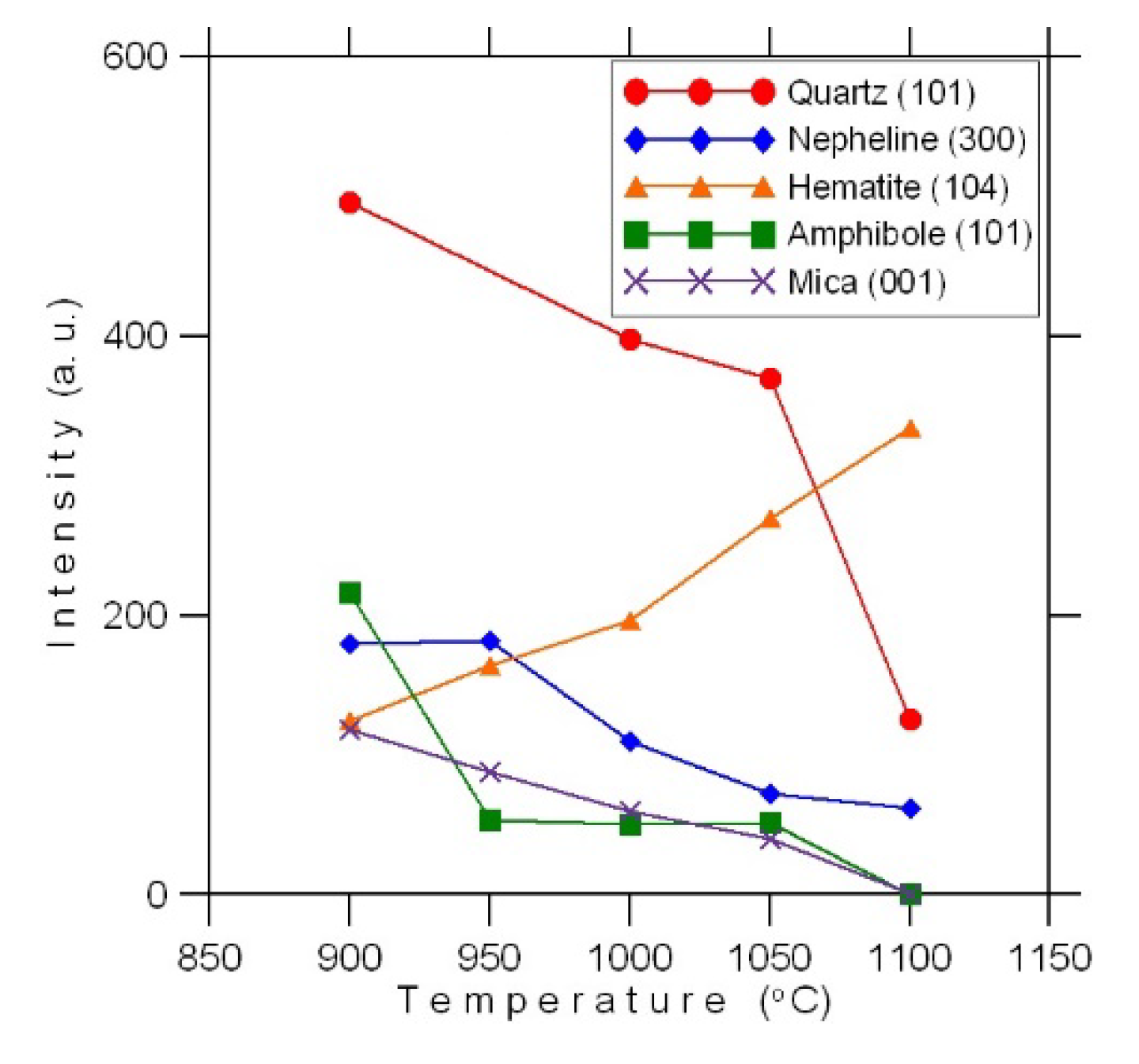
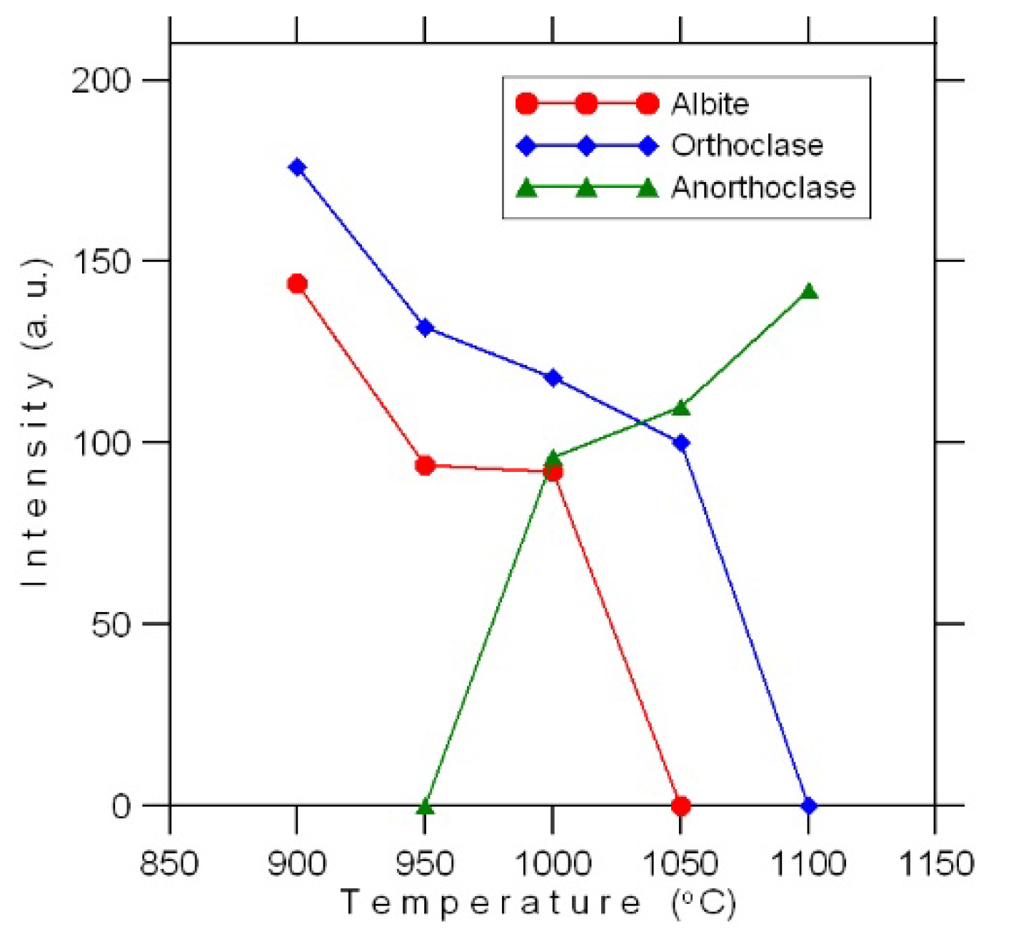
Figure 3: for each of the main phases we used the value of intensity shown at one of the peaks (e.g., peak (101) for quartz) at each firing temperature. Although this cannot be considered a quantitative analysis, those schemes, however, display the main fluctuation trends of phase composition under firing.
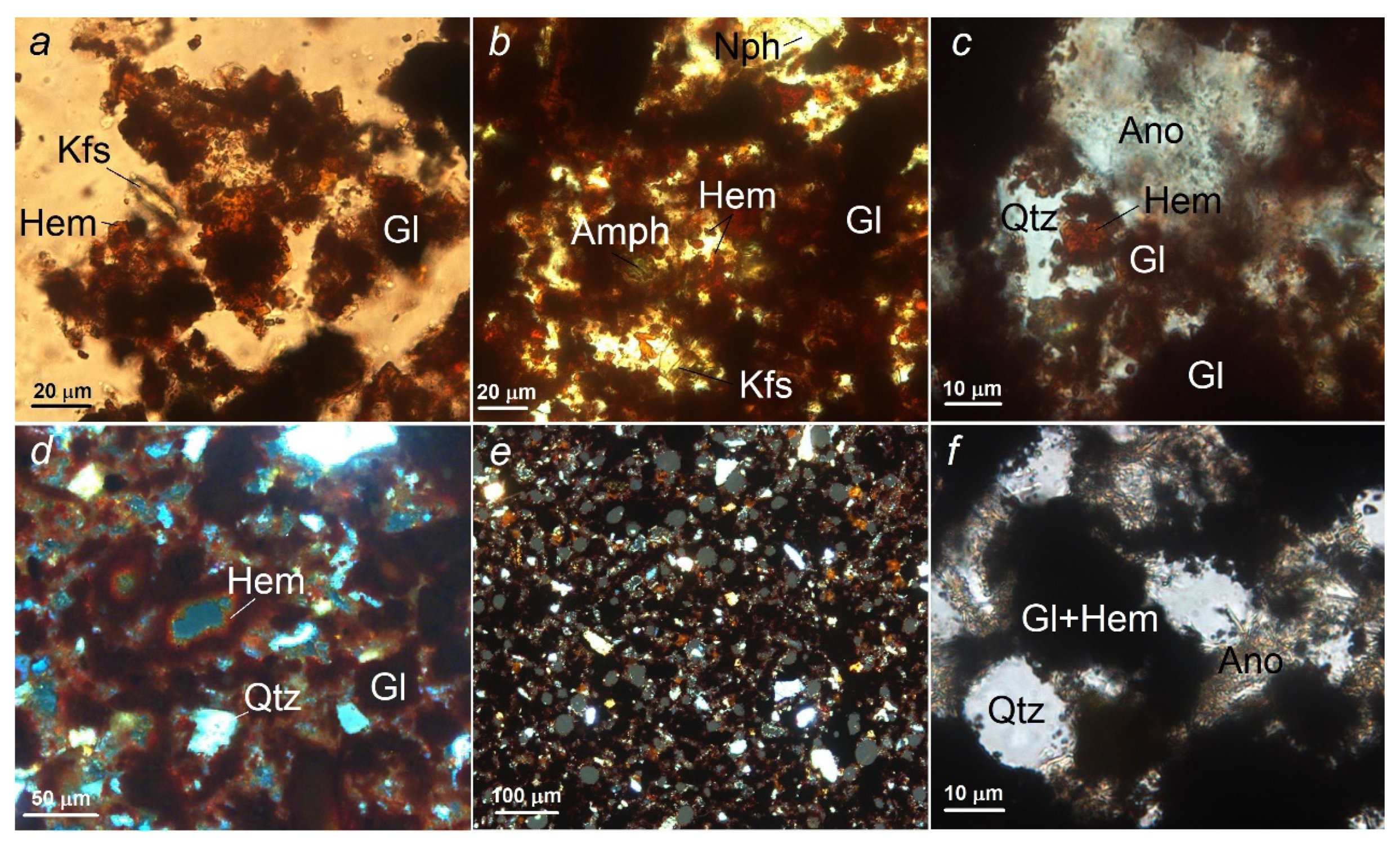
Physiochemical processes of firing samples at different temperatures can also be observed using a microscopic examination of a thin section as an example (
Figure 4).
Common to all samples is the presence in the glassy slag mass of finely impregnated spinel and sulfides, with the spinel content and its morphology preserved at all temperatures (
Figure 1).
After firing at 900 °C, the material is a loose mass, with only a slight modification of the initial phases. The material consists mainly of rounded, less often angular, fine quartz grains, relatively larger angular nepheline fragments with multiple fine-needle intergrowths of aegirine and flaky isometric particles of magnesian–ferrous glass framed by small sheets of hematite (
Figure 4a). The presence of hematite is the main difference between the ceramic material and the feed charge. The material also contains (in the descending order) angular fragments of amphibole, feldspar, annite, and titanite, rounded apatite grains.
Increasing the temperature to 950 °C leads to the sintering of the material due to intense melting and recrystallization of magnesian–iron glass with a parallel increase in the hematite content (
Figure 2 and
Figure 4b), which, together with glass, acts as cement. The cement holds together disparate grains of quartz, nepheline, amphibole, feldspar, and mica. Nepheline takes on a light brown tint. The content of amphibole and mica content in the material fired at 950 °C decreases significantly (
Figure 2), the same as that of feldspars (
Figure 3). The changes initiated in the glass do not affect magnetite and sulfides, which remain finely disseminated in the glass.
An important change in the phase composition of the material occurs when the temperature rises to 1000 °C at the periphery of nepheline and quartz grains, and when a crystalline phase forms at their common boundaries (
Figure 4c), which coincides with the emergence on the diffractogram of a K-Na-feldspar, anorthoclase (
Figure 3) Numerous cracks form in quartz grains, nepheline becomes even darker, its share decreases (
Figure 2) The share of fine crystalline hematite continues to grow, the glass melts intensively, forming thin translucent films of a dark brown color. The share of annite, compared to the material fired at a temperature of 950 °C, decreases noticeably; only single sheets are found in the glass. Amphibole is represented by single grains.
As the firing temperature increases to 1050 °C, the proportion of hematite continues to grow, while the proportion of quartz and nepheline continues to decrease due to the newly formed fine crystalline anorthoclase. Single grains of amphibole and mica were found. Small (up to 60 μm in diameter) isometric cavities, pores framed by small hematite sheets form in the material (
Figure 4d) The cavities have an uneven distribution, their combined area does not exceed 10% of the total area of the material.
The appearance of the material changes significantly when exposed to a firing temperature of 1100 °C. The cavities acquire a clearly rounded shape, increases markedly in number and make up 20–25% of the area (
Figure 4e) Fine-grained anorthoclase forms intensively on the quartz and nepheline grains (
Figure 4f), sometimes completely replacing them.
Changing the forming pressure from 20 to 100 MPa at a firing temperature of 1000 °C does not affect the phase composition of the material.
Comparing the phase transformations of the product described above with data obtained by us earlier for compositions containing tailings [
12], certain similarities can be seen. They lie in the simultaneous reduction of quartz and nepheline content with the formation of felspar as the firing temperature increases. The main difference is a sharp increase in hematite content with firing temperature growth, which occurs through the higher content of iron in slag, as well as through the existence of a glass-like matrix of slag particles subject to de-crystallization.
Our analysis of phase reactions and mineralogical transformations of the compositions is an experimental observation, and it allows us to explain trends of changing properties of ceramic materials. As is well known, complete equilibrium is not achievable in ceramic bulk. A number of local equilibriums exist because of incomplete homogenization. The higher the calcination temperature, the amount of melt in the ceramic phase, and the duration of isothermal exposure, the closer the system to equilibrium. In this regard, additional studies are necessary during industrial testing.
3.2. Compressive and Bending Strength
The change in compressive and bending strength depending on the forming pressure of ceramic materials obtained at various firing temperatures is shown in
Figure 5. There is an obvious increase in strength with increasing firing temperature.
With increasing forming pressure, there is also an increase in compressive and bending strength of samples except for those fired at 900 and 950 °C. For instance, the strength properties of the sample obtained at a forming pressure of 50 MPa and fired at 1050 °C match those of the sample formed at 20 MPa and fired at 1100 °C (
Figure 5).
The best strength performance was demonstrated by the sample obtained by forming at 100 MPa, followed by firing at 1100 °C: compressive strength 218.7, bending strength of 47.7 MPa (
Figure 5).
In terms of strength, the samples fired at 1050 and 1100 °C are comparable with clinker ceramics.
Note that replacing copper-nickel ore concentration tailings with slag at the same ratios of the other components improved the compressive strength of the samples fired at 1050 and 1100 °C and the bending strength of those fired at 1100 °C [
12]. This effect, on the one hand, can be associated with the formation and increase in the content of hematite, whose crystals act as a reinforcement. On the other hand, feldspars form more intensively, which contributes to the formation of fusible eutectics and melting with increasing firing temperature.
3.3. Bulk Density
Bulk density of the ceramic materials fired at 900, 950, and 1000 °C is virtually the same (
Figure 6). A slight increase in bulk density was observed with an increase in the forming pressure of the samples fired at these temperatures.
A significant increase in bulk density was observed in the samples fired at 1050 and 1100 °C (
Figure 6). Obviously, this is due to the amorphization of mineral phases such as mica and amphibole and the melting of some sections of the material, as evidenced by the presence of pores. At the same time, in the samples fired at these temperatures, there was no increase in density with an increase in forming pressure.
The increased bulk density of samples can be linked to the presence of hematite in ceramics. For the clinker brick, bulk density is not a constraining factor. For the wall brick, increased bulk density is a negative factor. However, the strength of the material allows the production of hollow constructions. This also reduces the thermal conductivity of constructions.
3.4. Fire Shrinkage
Fire shrinkage is the main process parameter in the manufacture of ceramic materials.
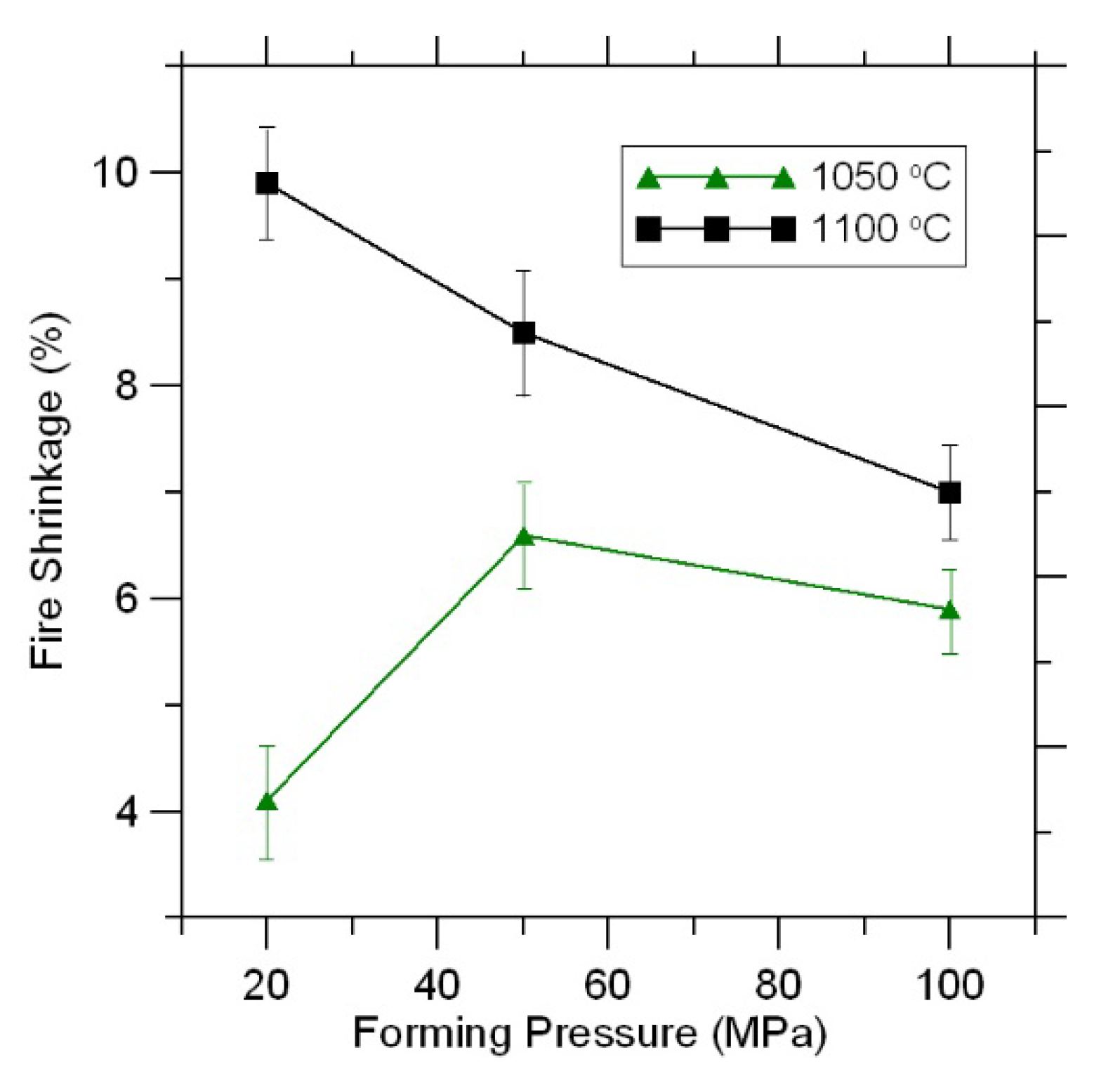
In ceramic materials fired at 900, 950, and 1000 °C, zero fire shrinkage was observed (
Figure 7).
Due to the melting of some sections of the material, fire shrinkage begins to increase in the samples fired at 1050 and 1100 °C with increasing firing temperature (
Figure 7).
In this case, with an increase in the molding pressure, the fire shrinkage of the samples sintered at the same temperature (1050 and 1100 °C) decreases slightly (
Figure 7).
In previous studies, firing shrinkage decreased with an increase in pressure. In the present research, such dependency was observed in samples fired at 1100 °C. The minimal shrinkage was registered for samples fired at 1050 °C under the pressure of 20 MPa, while the maximal shrinkage was registered under 50 MPa, and intermediary shrinkage was registered under 100 MPa. It is difficult to interpret the result unequivocally. One could speak of the impact of porosity linked to the dehydration of samples, the outburning of sulfite waste liquor, and the amount of forming melt.
It should be noted that the true density of samples fired at 1050 and 1100 °C does not change within the margin of error. In this case, the change in firing shrinkage under increasing pressure can be interpreted from the perspective of increasing reactivity and the amount of melt, which leads to the deformation of samples.
3.5. Water Absorption
Water absorption is one of the main properties of ceramic materials. The strength and frost resistance of both individual bricks and the building as a whole depend on this property.
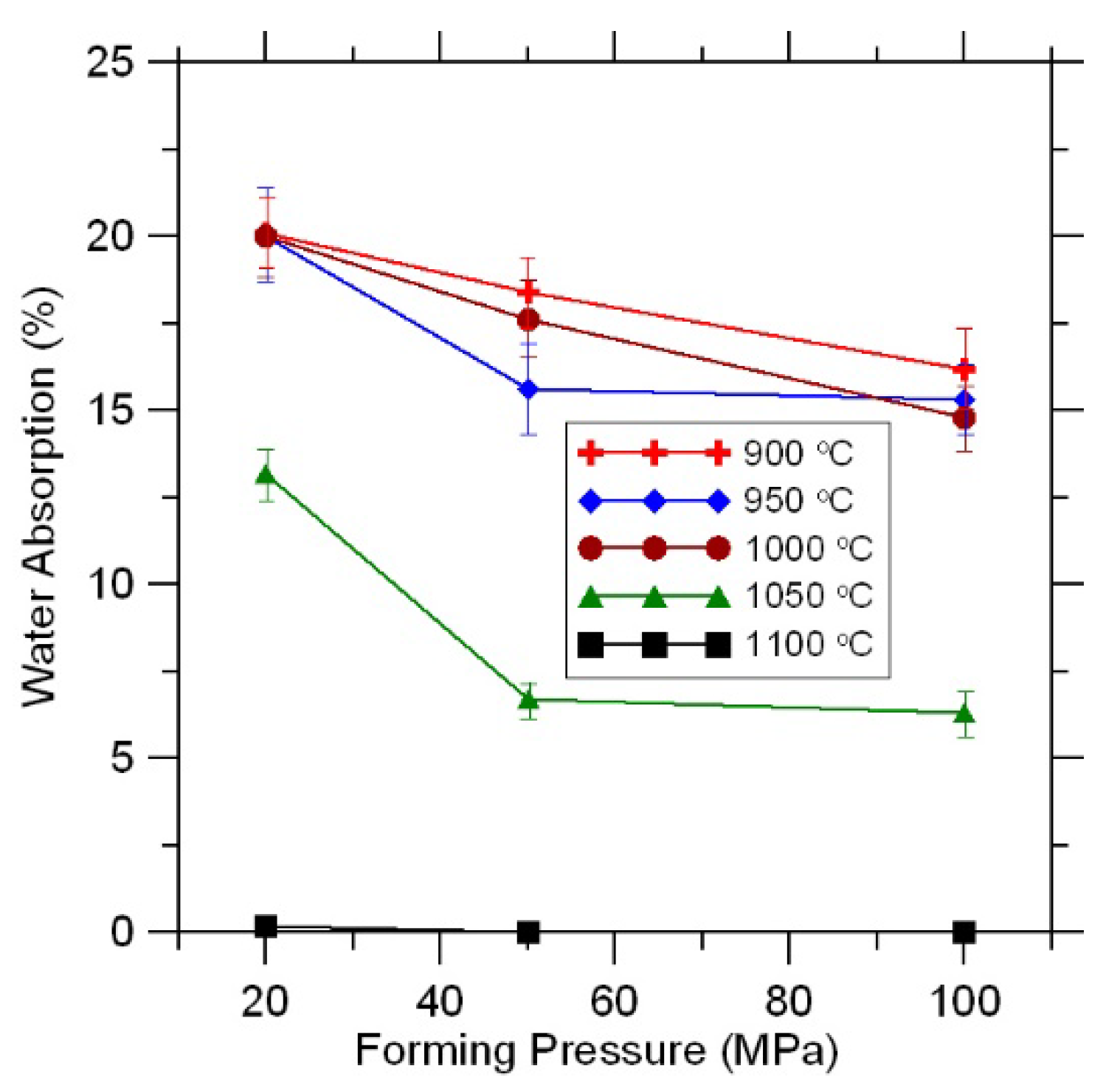
As expected, water absorption of the samples decreased with increasing firing temperature (
Figure 8).
A decrease in water absorption with increasing forming pressure was observed at all firing temperatures (
Figure 8).
The water absorption of samples fired at a temperature of 900–1000 °C allows us to recommend them for the production of wall materials for the inside constructions.
The water absorption of samples obtained under the pressure of 20 MPa and fired at 1050 °C meets the requirements of Russian standards for wall materials [
24].
The material obtained at a forming pressure of 100 MPa and fired at a temperature of 1050 °C is in terms of water absorption (6%) comparable to wall clinker brick (
Figure 8)
Samples fired at 1100 °C are characterized by a water absorption value close to zero (
Figure 8).
3.6. Frost Resistance
Frost resistance is a key factor to be considered when specifying brick products for a project, especially for exterior walls in the climatic conditions of Russia. Weather conditions, including ambient temperature, vary significantly during the year. This exposes brick structures to the risk of accelerated wear, cracking, and reduced service life.
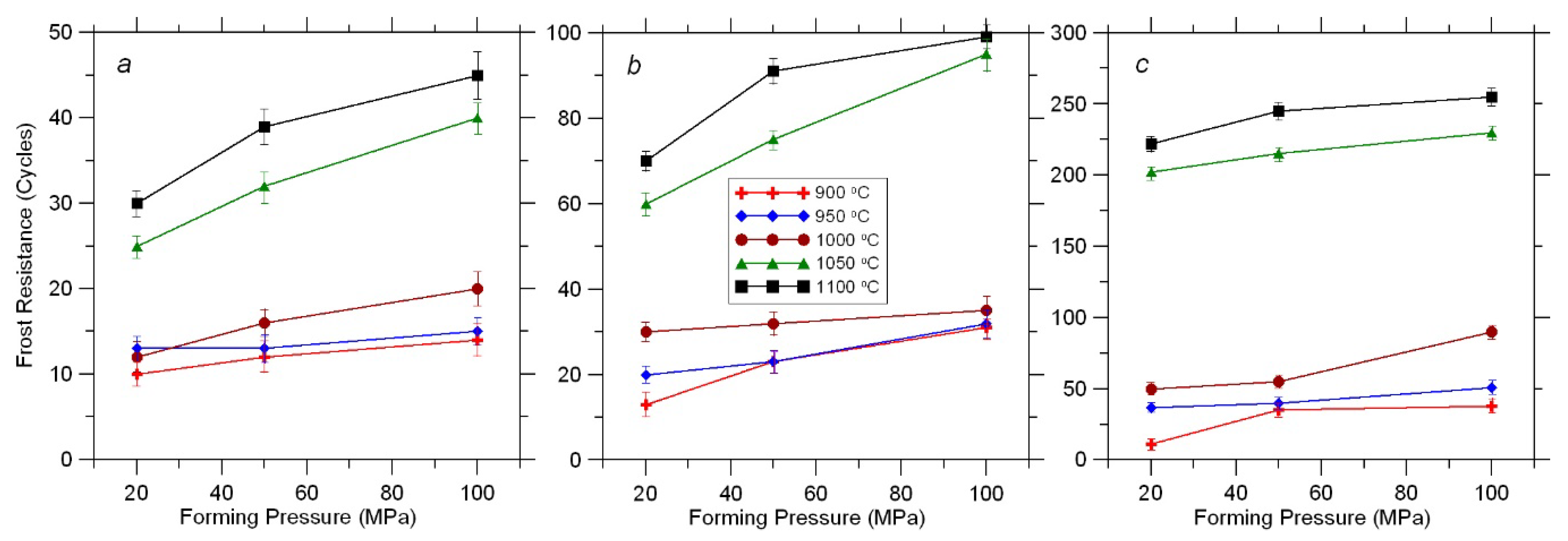
Ceramic samples obtained without additional processing involving the formation of a matrix structure are characterized by a low frost resistance of only 10–20 freezing–thawing cycles (
Figure 9a).
However, the samples treated with water repellent and fired at 950–1000 °C withstood 35 cycles, while those fired at 1050–1100 °C, withstood 100 cycles (
Figure 9b).
Using a granular molding powder in the production process provides increased frost resistance of ceramic materials. Thus obtained samples fired at 1000–1100 °C withstood more than 200 alternate freezing and thawing cycles (
Figure 9c).
4. Conclusions
Therefore, the possibility of extension of mineral and raw material base for building material industry and reduction of demand for primary resources was shown. The ceramic materials made of non-flexible secondary raw-materials with increased strength and high frost resistance were obtained.
Dumped granular copper-nickel slag can, when blended with concentration tailings of apatite-nepheline ore and ferruginous quartzite, be used for the production of compression-molded ceramic building materials. The following charge formula provides a balanced chemical composition of the resulting ceramics and the optimal phase composition: copper–nickel slag 40%, apatite–nepheline ore concentration tailings 40%, iron ore concentration tailings 20%.
XRD and optical microscopy showed an increase in the content of the oxide phase (hematite) and the formation of K-Na feldspar with increasing firing temperature with the formation of oxide-feldspar ceramics. Hematite forms due to silicate phases, in this case, mainly due to the de-crystallization of the glassy matrix of slag particles.
The following effects of the firing temperature and forming pressure on the properties of the resulting ceramic materials were observed:
(1) With increasing firing temperature, compressive and bending strength, bulk density, and fire shrinkage increase, while water absorption decreases.
(2) With increasing forming pressure, there is also an increase in compressive and bending strength of samples except for those fired at 900 and 950 °C. In terms of strength, the samples fired at 1050 and 1100 °C were comparable with clinker ceramics.
(3) With an increase in forming pressure, the bulk density of the samples fired at 900, 950, and 1000 °C increased slightly. A significant increase in bulk density was observed in the samples fired at 1050 and 1100 °C.
(4) As expected, water absorption of the samples decreased with increasing sintering temperature and forming pressure. Materials obtained at a forming pressure of 100 MPa and fired at 1050 °C, as well as at 20–100 MPa and 1100 °C, are in terms of water absorption comparable with clinker ceramics.
(5) Additional process methods (hydrophobization, the formation of a matrix structure) in the manufacture of ceramic materials demonstrated the possibility of obtaining semi-dry forming products with increased frost resistance. Increasing the sintering temperature contributes to a significant increase in frost resistance. Samples that were compression formed from granular molding powders and fired at 1000–1100 °C had the highest frost resistance of 200 cycles.
(6) Based on a combination of the measured properties, it was found that at a forming pressure of 100 MPa and a firing temperature of 1050 °C, wall clinker brick can be produced, and at a firing temperature of 1100 °C and a forming pressure of 20–100 MPa, paving clinker brick.
The phase transformations underlying the high strength properties of the ceramics produced using this charge formula require a more detailed study since these are of interest to a wider range of material science problems.
Additional studies are necessary during industrial testing.
Author Contributions
Conceptualization, O.V.S., E.A.S., J.A.M., V.A.M. and D.V.M.; Methodology, O.V.S., E.A.S., J.A.M., V.A.M. and D.V.M.; Investigation, O.V.S., E.A.S., J.A.M., V.A.M. and D.V.M.; Writing-Original Draft Preparation, O.V.S., E.A.S., J.A.M., V.A.M. and D.V.M.; Writing-Review & Editing, O.V.S., E.A.S., J.A.M., V.A.M. and D.V.M.; Visualization, O.V.S., E.A.S., J.A.M., V.A.M. and D.V.M. All authors have read and agree to the published version of the manuscript.
Funding
This research was funded by the Russian Government, grants no. 0226-2019-0047, 0226-2019-0068. The research was financially supported by the Kolarctic CBC 2014-2020 program (project no.KO1030 “Supporting Environmental Economic and Social Impacts of Mining Activity”) and the Russian Foundation for Basic Research (project No. 18-05-60142 Arctic).
Conflicts of Interest
The authors declare no conflict of interest.
References
- Chanturia, V.A.; Chaplygin, N.N.; Vigdergauz, V.E. Resource-saving technology for the processing of minerals and environmental protection. Min. J. 2007, 2, 91–96. [Google Scholar]
- Muñoz, V.P.; Morales, O.M.P.; Mendívil, G.M.A.; Muñoz, V.L. Fired clay bricks manufactured by adding wastes as sustainable construction material—A review. Constr. Build. Mater. 2014, 63, 97–107. [Google Scholar] [CrossRef]
- Monteiro, S.N.; Fontes Vieira, C.M. On the production of fired clay bricks from waste materials: A critical update. Constr. Build. Mater. 2014, 68, 599–610. [Google Scholar] [CrossRef]
- Muñoz, V.P.; Morales, O.M.P.; Letelier, G.V.; Mendívil, G.M.A. Fired clay bricks made by adding wastes: Assessment of the impact on physical, mechanical and thermal properties. Constr. Build. Mater. 2016, 125, 241–252. [Google Scholar] [CrossRef]
- Roy, S.; Adhikari, G.R.; Gupta, R.N. Use of gold mill tailings in making bricks: A feasibility study. Waste Manage. Res. 2007, 25, 475–482. [Google Scholar] [CrossRef]
- Suvorova, O.V.; Makarov, D.V.; Pletneva, V.E. Ceramic materials based on tailings from enrichment of vermiculite and apatite-nepheline ores. Glass Ceram. 2009, 66, 255–257. [Google Scholar] [CrossRef]
- Chen, Y.; Zhang, Y.; Chen, T.; Zhao, Y.; Bao, S. Preparation of eco-friendly construction bricks from hematite tailings. Constr. Build. Mater. 2011, 25, 2107–2111. [Google Scholar] [CrossRef]
- Yang, C.; Cui, C.; Qin, J.; Cui, X. Characteristics of the fired bricks with low-silicon iron tailings. Constr. Build. Mater. 2014, 70, 36–42. [Google Scholar] [CrossRef]
- Liu, W.; Wu, T.; Li, Z.; Hao, X.; Lu, A. Preparation and characterization of ceramic substrate from tungsten mine tailings. Constr. Build. Mater. 2015, 77, 139–144. [Google Scholar] [CrossRef]
- Shcherbina, N.F.; Kochetkova, T.V. Use of iron-ore enrichment tailings in the production of ceramic articles. Glass Ceram. 2016, 73, 22–24. [Google Scholar] [CrossRef]
- Pavlov, M.V.; Pavlov, I.V.; Lineitsev, A.V.; Pavlov, V.F. Glass ceramic materials based on beneficiation tailings of lead-zinc ore. Glass Ceram. 2017, 73, 459–464. [Google Scholar] [CrossRef]
- Suvorova, O.; Kumarova, V.; Nekipelov, D.; Selivanova, E.; Makarov, D.; Masloboev, V. Construction ceramics from ore dressing waste in Murmansk region, Russia. Constr. Build. Mater. 2017, 153, 783–789. [Google Scholar] [CrossRef]
- Shih, P.H.; Wu, Z.Z.; Chiang, H.L. Characteristics of bricks made from waste steel slag. Waste Manag. 2004, 24, 1043–1047. [Google Scholar] [CrossRef] [PubMed]
- Suleimenov, Z.T.; Sagyndykov, A.A.; Kirgizbaev, A.T. Ceramic face tiles using phosphoric slags. Glass Ceram. 2016, 73, 62–65. [Google Scholar] [CrossRef]
- Nevskaya, M.A.; Seleznev, S.G.; Masloboev, V.A.; Klyuchnikova, E.M.; Makarov, D.V. Environmental and business challenges presented by mining and mineral processing waste in the Russian Federation. Minerals 2019, 9, 445. [Google Scholar] [CrossRef] [Green Version]
- Wang, Z.J.; Ni, W.; Jia, Y.; Zhu, L.P.; Huang, X.Y. Crystallization behavior of glass ceramics prepared from the mixture of nickel slag, blast furnace slag and quartz sand. J. Non-Cryst. Solids 2010, 356, 1554–1558. [Google Scholar] [CrossRef]
- Wu, Q.; Wu, Y.; Tong, W.; Ma, H. Utilization of nickel slag as raw material in the production of Portland cement for road construction. Constr. Build. Mater. 2018, 193, 426–434. [Google Scholar] [CrossRef]
- Yang, T.; Yao, X.; Zhang, Z. Geopolymer prepared with high-magnesium nickel slag: Characterization of properties and microstructure. Constr. Build. Mater. 2014, 59, 188–194. [Google Scholar] [CrossRef]
- Wang, Q.; Yu, C.; Yang, J.; Chong, L.; Xu, X.; Xu, X.; Wu, Q. Influence of nickel slag powders on properties of magnesium potassium phosphate cement paste. Constr. Build. Mater. 2019, 205, 668–678. [Google Scholar] [CrossRef]
- Stolboushkin, A.Y.; Vereshchagin, V.I.; Fomina, O.A. Phase composition of the core-shell transition layer in a construction ceramic matrix structure made from non-plastic raw material with clay additives. Glass Ceram. 2019, 76, 16–21. [Google Scholar] [CrossRef]
- Barnat-Hunek, D.; Smarzewski, P.; Suchorab, Z. Effect of hydrophobisation on durability related properties of ceramic brick. Constr. Build. Mater. 2016, 111, 275–285. [Google Scholar] [CrossRef]
- Water repellent ECOTERRA Aqua protect No1. Available online: https://stroyudacha.ru/products/1743-gidrofobizator-ecoterra-aqua-protect--1-5-l.html (accessed on 19 May 2020).
- GOST 8462-85. Wall Materials. Methods for Determination of Ultimate Compressive and Bending Strength. Available online: http://docs.cntd.ru/document/901700489 (accessed on 19 May 2020).
- GOST 7025-91. Ceramic and Calcium Silicate Bricks and Stones. Methods for Water Absorption and Density Determination and Frost Resistance Control. Available online: http://docs.cntd.ru/document/901700526 (accessed on 19 May 2020).
- GOST 27180-2001. Ceramic tiles. Test Methods. Available online: http://docs.cntd.ru/document/1200028668 (accessed on 19 May 2020).
- Makarov, D.V.; Potapov, D.S.; Potapov, S.S.; Svetlov, A.V. Study of the environmental hazard and the potential ability to extract useful components from granulated slag of the “Pechenganickel” combine “Kola Mining and Metallurgical Company” JSC. Ind. Ecol. 2013, 3, 54–58. [Google Scholar]
© 2020 by the authors. Licensee MDPI, Basel, Switzerland. This article is an open access article distributed under the terms and conditions of the Creative Commons Attribution (CC BY) license (http://creativecommons.org/licenses/by/4.0/).

