Modes Control of Lamb Wave in Plates Using Meander-Line Electromagnetic Acoustic Transducers


Abstract
:1. Introduction
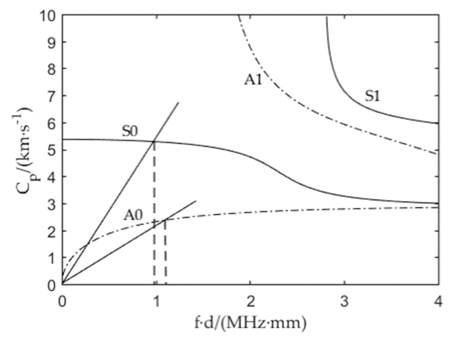
2. Lamb Waves
3. Mode Control of Lamb Waves
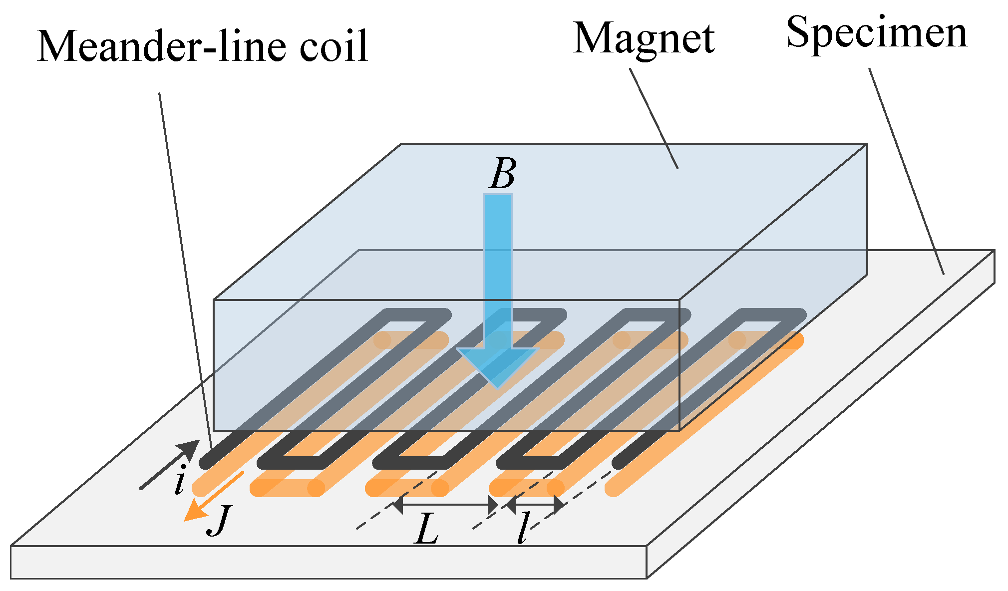
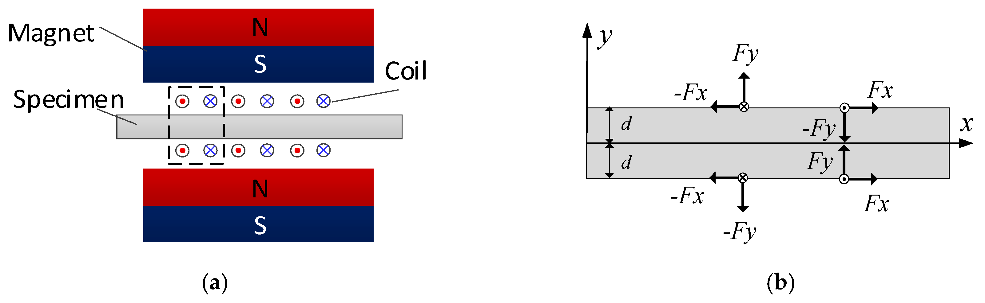
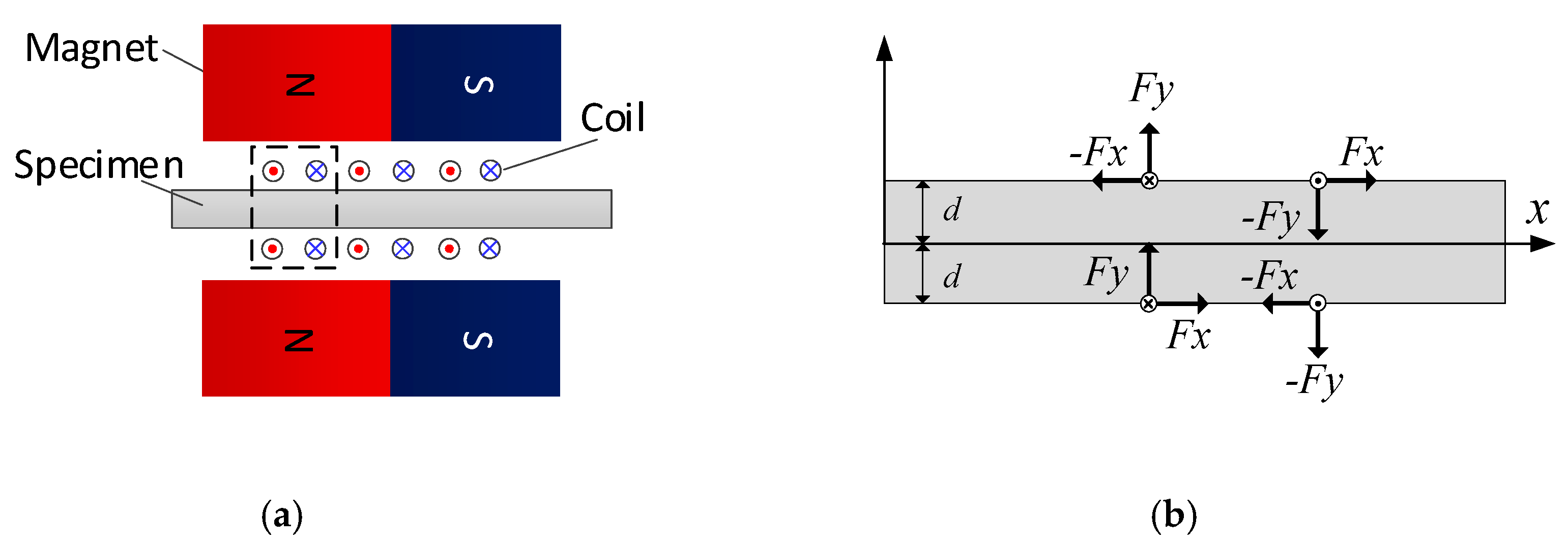
3.1. Fundamentals of Meander-Line EMAT
3.2. Modes Control with Paired EMAT Configurations
4. Verifications
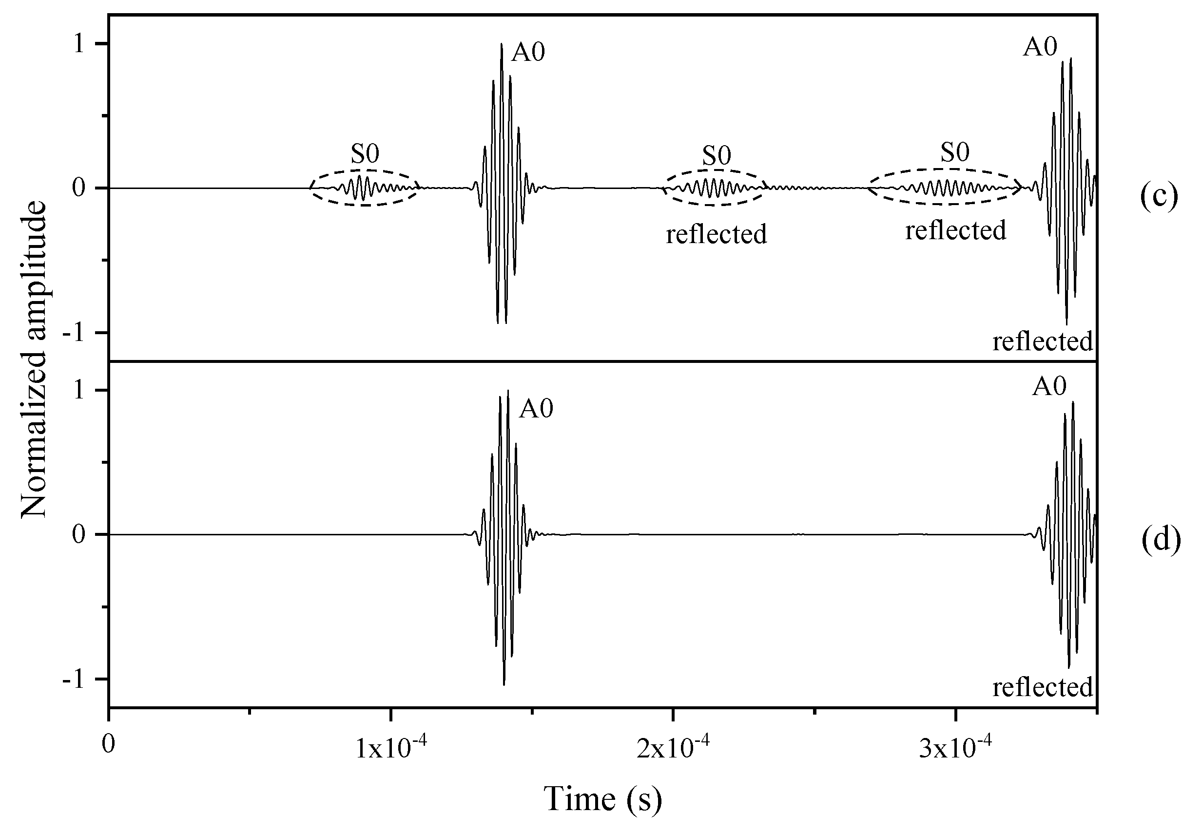
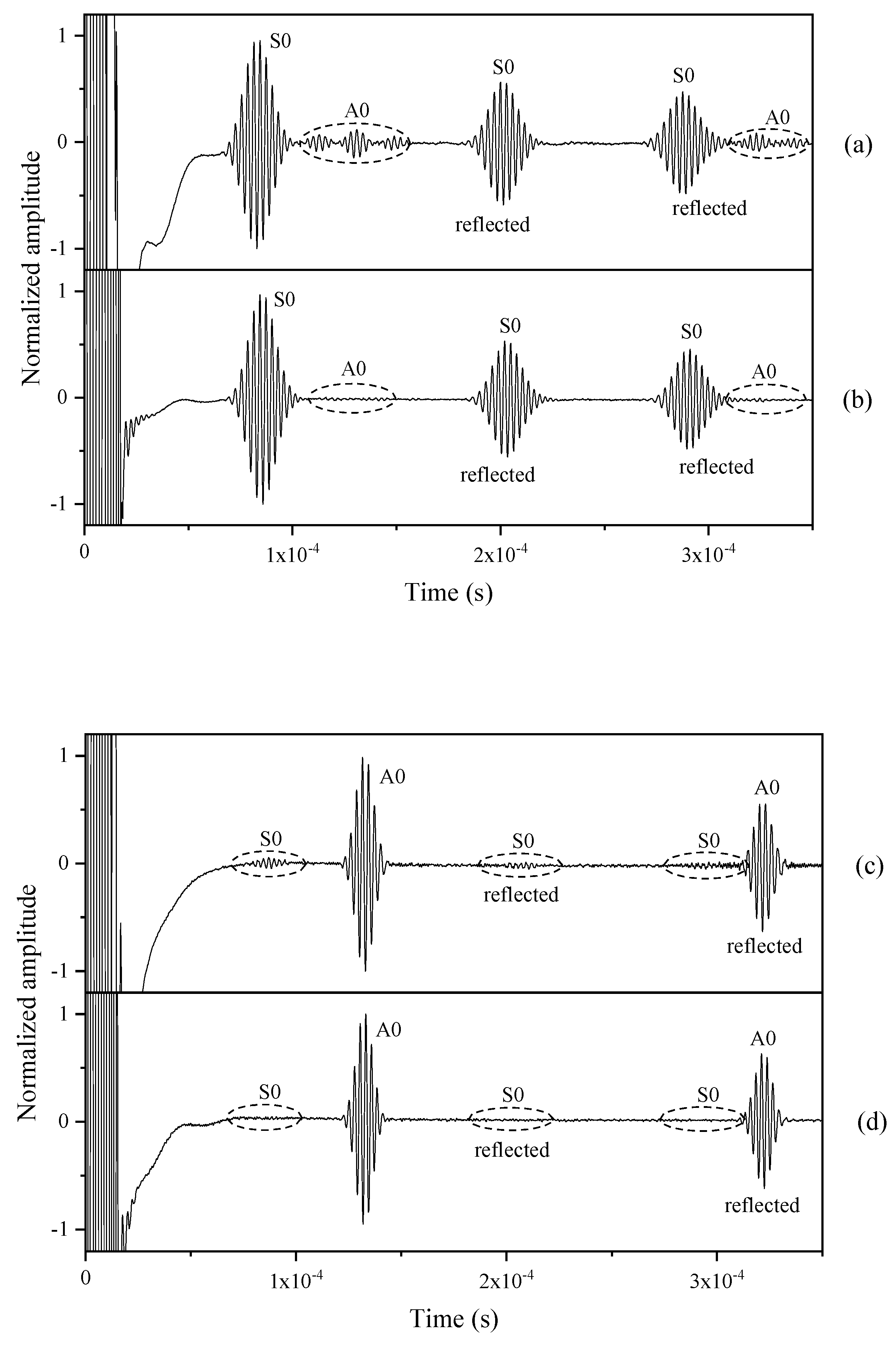
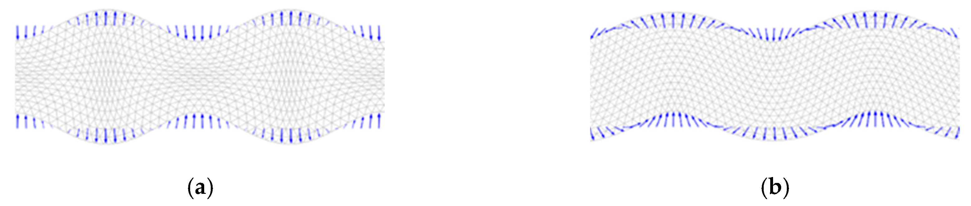
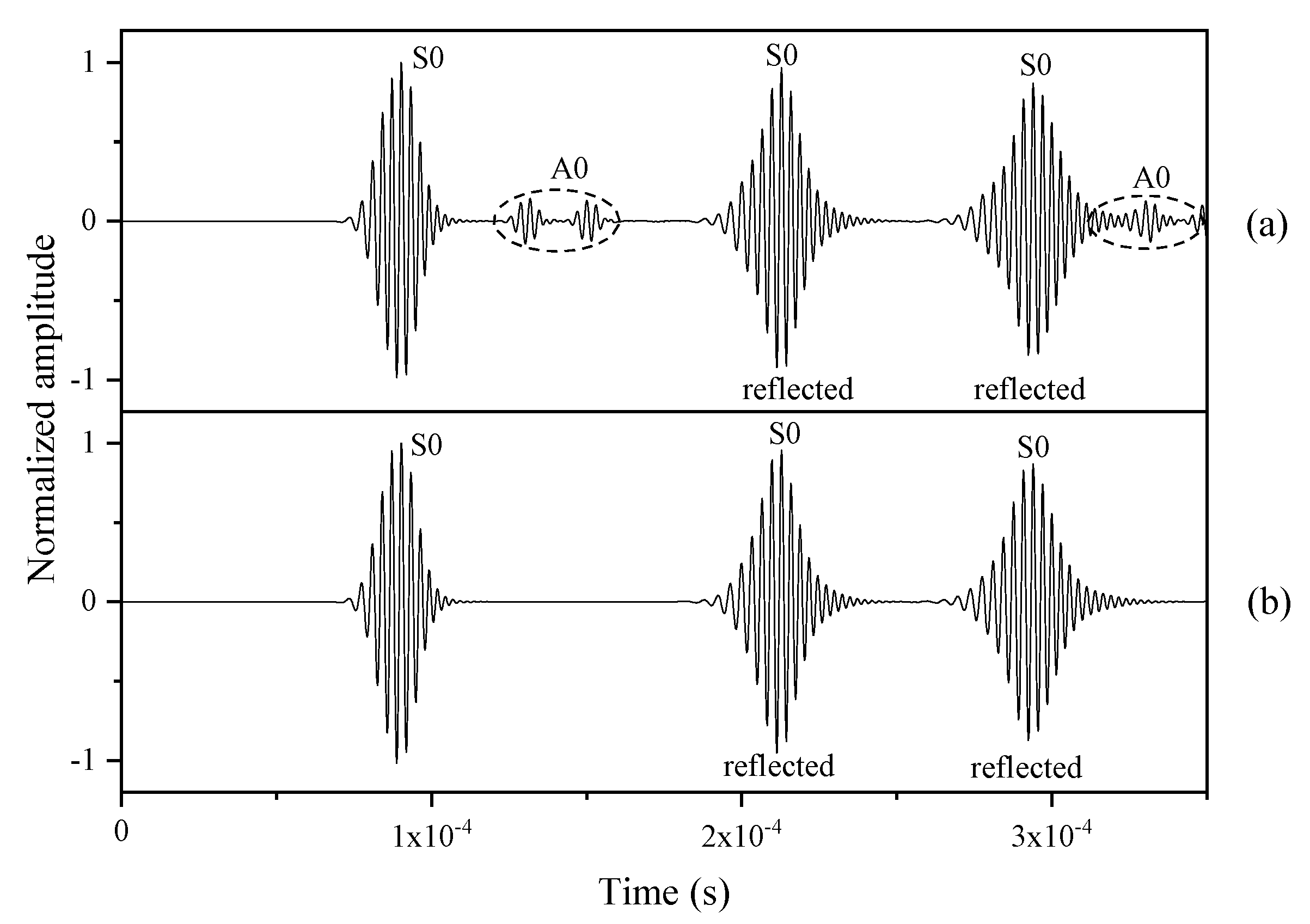
4.1. Simulation for Modes Control of Lamb Waves
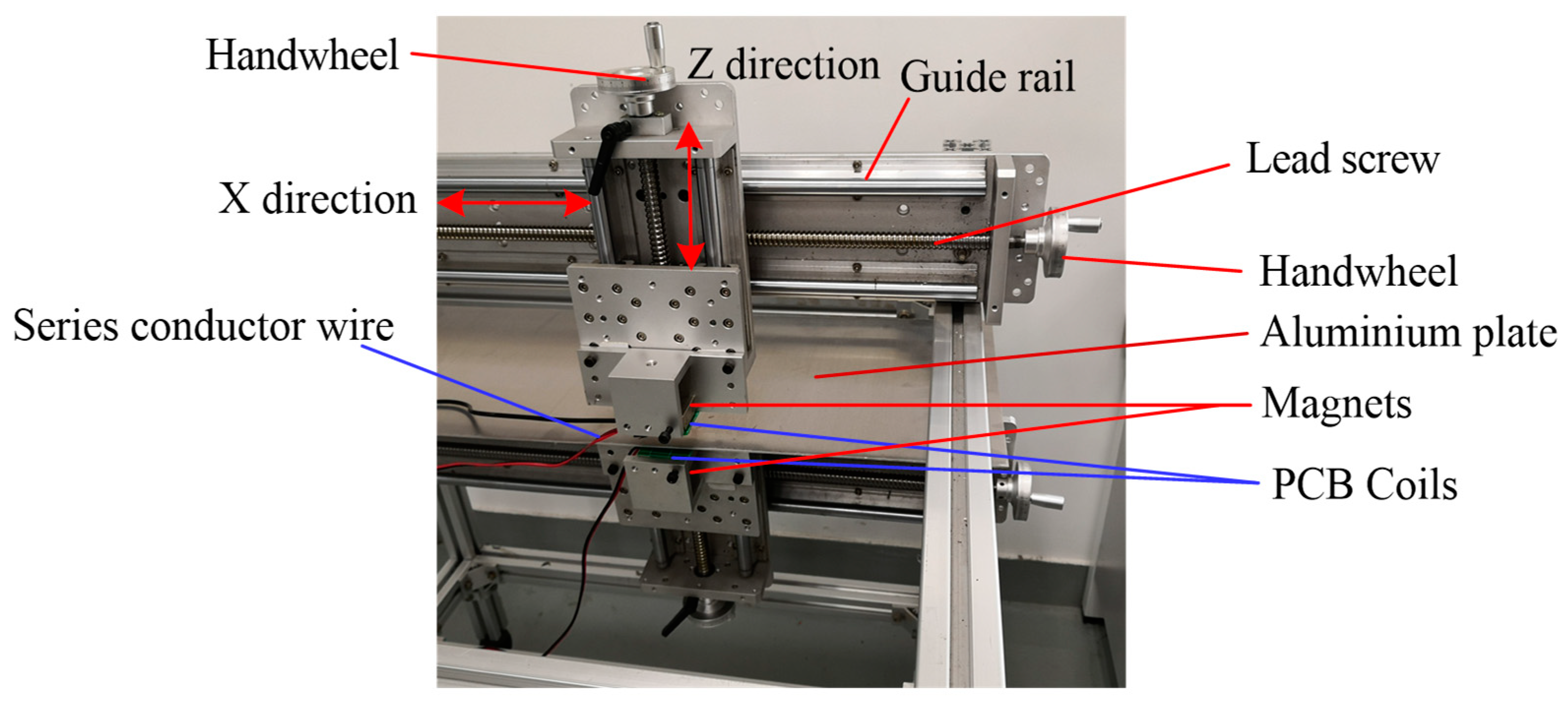
4.2. Experimental Setup
5. Conclusions
Author Contributions
Acknowledgments
Conflicts of Interest
References
- Dalton, R.P.; Cawley, P.; Lowe, M.J.S. The Potential of Guided Waves for Monitoring Large Areas of Metallic Aircraft Fuselage Structure. J. Nondestruct. Eval. 2001, 20, 29–46. [Google Scholar] [CrossRef]
- Huang, S.L.; Wei, Z.; Zhao, W.; Wang, S. A New Omni-Directional EMAT for Ultrasonic Lamb Wave Tomography Imaging of Metallic Plate Defects. Sensors 2014, 14, 3458–3476. [Google Scholar] [CrossRef] [PubMed] [Green Version]
- Kojima, F.; Furusawa, A.; Ito, T. Impact Model and Control of Ultrasonic Excitation using Electromagnetic Acoustic Transducer. In Proceedings of the 2015 10th Asian Control Conference (Ascc), Sabah, Malaysia, 31 May–3 June 2015; 2015. [Google Scholar]
- Su, Z.; Ye, L.; Lu, Y. Guided Lamb waves for identification of damage in composite structures: A review. J. Sound Vib. 2006, 295, 753–780. [Google Scholar] [CrossRef]
- Li, D.; Zhang, S.; Yang, W.; Zhang, W. Corrosion Monitoring and Evaluation of Reinforced Concrete Structures Utilizing the Ultrasonic Guided Wave Technique. Int. J. Distrib. Sens. Netw. 2014, 10, 827130. [Google Scholar] [CrossRef]
- Shen, W.; Li, D.; Zhang, S.; Ou, J. Analysis of wave motion in one-dimensional structures through fast-Fourier-transform-based wavelet finite element method. J. Sound Vib. 2017, 400, 369–386. [Google Scholar] [CrossRef]
- Su, Z.; Ye, L. Selective generation of Lamb wave modes and their propagation characteristics in defective composite laminates. J. Mater. Des. Appl. 2004, 218, 95–110. [Google Scholar] [CrossRef]
- Koduru, J.P.; Rose, J.L. Transducer arrays for omnidirectional guided wave mode control in plate like structures. Smart Mater. Struct. 2013, 22, 015010. [Google Scholar] [CrossRef]
- Glushkov, E.V.; Glushkova, N.V.; Kvasha, O.V.; Lammering, R. Selective Lamb mode excitation by piezoelectric coaxial ring actuators. Smart Mater. Struct. 2010, 19, 035018. [Google Scholar] [CrossRef]
- Giurgiutiu, V. Tuned Lamb Wave Excitation and Detection with Piezoelectric Wafer Active Sensors for Structural Health Monitoring. J. Intell. Mater. Syst. Struct. 2016, 16, 291–305. [Google Scholar] [CrossRef]
- Seher, M.; Huthwaite, P.; Lowe, M.J.S.; Nagy, P.B. Model-Based Design of Low Frequency Lamb Wave EMATs for Mode Selectivity. J. Nondestruct. Eval. 2015, 34. [Google Scholar] [CrossRef] [Green Version]
- Lee, J.K.; Kim, Y.Y. Tuned double-coil EMATs for omnidirectional symmetric mode lamb wave generation. NDT E Int. 2016, 83, 38–47. [Google Scholar] [CrossRef]
- Sun, W.; Liu, G.; Xia, H.; Xia, Z. A modified design of the omnidirectional EMAT for antisymmetric Lamb wave generation. Sens. Actuators A Phys. 2018, 282, 251–258. [Google Scholar] [CrossRef]
- Liu, Z.; Hu, Y.; Xie, M.; Wu, B.; He, C. Development of omnidirectional A 0 mode EMAT employing a concentric permanent magnet pairs with opposite polarity for plate inspection. NDT E Int. 2018, 94, 13–21. [Google Scholar] [CrossRef]
- Graff, K.F. Wave Motion in Elastic Solids; Courier Corporation: Oxford, UK; p. 1975.
- Achenbach, J.D. Wave Propagation in Solids; North-Holland Publishing Company: Amsterdam, The Netherlands, 1999. [Google Scholar]
- Rose, J.L. Ultrasonic Waves in Solid Media; Cambridge University Press: Cambridge, UK, 1999. [Google Scholar]
- Kaltenbacher, M.; Ettinger, K.; Lerch, R. Finite element analysis of coupled electromagnetic acoustic systems. IEEE Trans. Magn. 1999, 35, 1610–1613. [Google Scholar] [CrossRef]
- Murayama, R. Driving mechanism on magnetostrictive type electromagnetic acoustic transducer for symmetrical vertical mode Lamb wave and for shear horizontal mode plate wave. Ultrasonics 1996, 34, 729–736. [Google Scholar] [CrossRef]
- Ashigwuike, E.C.; Ushie, O.J.; Mackay, R.; Balachandran, W. A study of the transduction mechanisms of electromagnetic acoustic transducers (EMATs) on pipe steel materials. Sens. Actuators A Phys. 2015, 229, 154–165. [Google Scholar] [CrossRef]
- Wilcox, P.D.; Dalton, R.P.; Lowe, M.J.S.; Cawley, P. Mode and Transducer Selection for Long Range Lamb Wave Inspection. Key Eng. Mater. 1999, 167–168, 152–161. [Google Scholar] [CrossRef]


| Mode | Phase Velocity (m/s) | Frequency Thickness Product (MHz·mm) | Center Frequency (kHz) | Magnet (mm) | Wavelength (mm) | Plate Thickness (mm) |
|---|---|---|---|---|---|---|
| S0 | 5262 | 0.984 | 328 | 57 × 37 × 17 | 16 | 3 |
| A0 | 2442 | 1.1 | 366.7 | 37 × 37 × 37 | 6.3 | 3 |
© 2020 by the authors. Licensee MDPI, Basel, Switzerland. This article is an open access article distributed under the terms and conditions of the Creative Commons Attribution (CC BY) license (http://creativecommons.org/licenses/by/4.0/).
Share and Cite
Zhang, Y.; Qian, Z.; Wang, B. Modes Control of Lamb Wave in Plates Using Meander-Line Electromagnetic Acoustic Transducers. Appl. Sci. 2020, 10, 3491. https://doi.org/10.3390/app10103491
Zhang Y, Qian Z, Wang B. Modes Control of Lamb Wave in Plates Using Meander-Line Electromagnetic Acoustic Transducers. Applied Sciences. 2020; 10(10):3491. https://doi.org/10.3390/app10103491
Chicago/Turabian StyleZhang, Yinghong, Zhenghua Qian, and Bin Wang. 2020. "Modes Control of Lamb Wave in Plates Using Meander-Line Electromagnetic Acoustic Transducers" Applied Sciences 10, no. 10: 3491. https://doi.org/10.3390/app10103491
APA StyleZhang, Y., Qian, Z., & Wang, B. (2020). Modes Control of Lamb Wave in Plates Using Meander-Line Electromagnetic Acoustic Transducers. Applied Sciences, 10(10), 3491. https://doi.org/10.3390/app10103491