1. Introduction
The car became the most used audio listening environment for high-quality audio output [
1]. On the one hand, the in-car audio experience is getting even more important considering increasing leisure time coming, with progressing autonomous driving [
2]. On the other hand, the persisting trend towards lightweight designs due to energy saving causes a decrease of the system’s damping and hence increased cabin noise level [
3]. Using conventional loudspeaker design, a sufficient acoustical quality can be reached. However, the increasing number of speakers and peripherals significantly increases the overall car mass [
4]. A promising alternative is posed by a flat panel loudspeaker design, due to its lower mass and invisible integration [
5]. Such loudspeakers use vibrations of existing components with sufficient surface, which are excited by an electro-mechanical transducer [
6]. The usage of piezoceramics as an alternative to an electro-mechanical transducer has been known for a considerable time [
7,
8]. In particular, the small installation thickness and the low weight are outstanding and allow new interior design concepts. However, the interaction between the used material, geometry of the structure, type and integration position of the piezoelectric based flat panel loudspeaker has to be well understood to use such a design in everyday applications. This knowledge can be gained either by an extensive experimental study or by a numerical design in simulated environments, to ensure satisfactory acoustic characteristics [
9,
10,
11]. A challenging aspect results from the fact that the exciter position determines the dynamic response of the structure [
12] and hence, efficient vibration excitation in the given frequency range. In the current paper, an adaptronic, piezoceramic-driven loudspeaker for an automotive door side panel is presented, which is characterized by low weight, low installation space, and a good possibility to integrate during the manufacturing process. The door side panel itself is manufactured using the long fiber injection (LFI) process—a fully automated polyurethane spraying process with fiber reinforcement—which has been developed for the production of large-scale components [
13,
14,
15,
16]. Moreover, this process enables the possibility of manufacturing lightweight components with integrated sensors and actuators [
17]. This fact results from the moderate process-intrinsic loads (in particular low reaction temperatures and cavity pressures) [
18]. Additionally, the large variability of material- and process-specific parameters results in a broad spectrum of mechanical properties. Thus, for example, by the adaptation of fiber length, fiber mass content and composite density as well as the integration of continuous fiber reinforcements, tailor-made composite properties can be achieved [
19,
20].
The presented study is structured as follows:
Numerical pre-design to ensure efficient radiation, where the position of the piezoceramics is determined based on a finite element model;
Validation of the simulation data by measuring the surface velocity with laser vibrometry on a prototype with externally bonded piezoceramic exciters;
Selection of the most promising integration positions;
Manufacturing of the door side panel with structure-integrated piezoceramics;
Assessment of the acoustic performance of all manufactured structures.
Based on the results of the above described studies, guidelines for the design of structure-integrated loudspeakers using fiber-reinforced polyurethanes and piezoelectric transducers were derived.
2. Numerical Pre-Design Regarding Positioning of Adaptronic Loudspeakers
The following section presents a preliminary assessment of the door structure using numerical analysis to reduce the sound transmission of structure-borne sound, and avoid unwanted vibrations of the support structure and adjacent structures. A comparison of possible areas, which are suitable for the integration of the piezoceramic transducers, is demonstrated with an abstracted finite element (FE)-model. The main difference of the integration areas are their radiating surface and edge stiffness.
The calculation of force-excited surface vibrations was conducted with a FE-solver implemented into the software tool wave6 [
21]. It is well known that the choice of element type and size is related to the upper-frequency limit of the simulation and the resulting wavelength. In this study, the bending wavelength
is the limiting factor. Considering the thickness
h of 3 mm, which is determined by the mold geometry, a Young’s Modulus
E of 4 GPa, and a density
ρ of 500 kg/m
3 [
20], the bending stiffness
B equals to 9.89 Nm and the mass per unit area
m″ =
ρ·
h to 1.5 kg/m
2; at a frequency
of 5000 Hz, the wavenumber yields [
22]:
The wavelength results in the direct relationship, presented in Equation (2), from wavenumber
and wavelength
:
Additionally, the loss factor was set to 2%. The model was built using CQUAD8 elements with an element length
of 9 mm, to have at least 6 elements per bending wavelength:
Furthermore, a convergence analysis with the h-refinement procedure was performed to estimate the error of the FE-solution based on the difference of the calculated eigenfrequencies. The number of calculated eigenmodes
is 500, to calculate the eigenfrequencies up to 5300 Hz. Different mesh sizes are considered and compared with a reference mesh of 2.5 mm element length. The error
between the eigenfrequency of the reference mesh
and the eigenfrequency of a coarsed mesh
are calculated with the following Equation (4):
The element type of all mesh sizes is CQUAD8.
Figure 1 shows a strong correlation of mesh size and the error
. By analysing the results of different mesh refinements, it can be assumed that the result for 9 mm element length has converged and causes errors of less than 1%. The whole FE model includes 25,712 CQUAD8 elements.
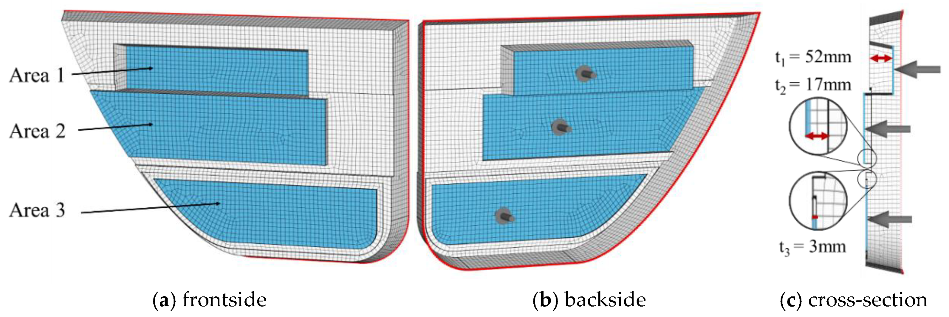
The meshed simulation model is shown in
Figure 2. The free edges of the model have been clamped in all translation and rotation directions (marked red). The piezoceramic was abstracted as point force and placed at 1/3 of the total length of each possible integration area. The possible integration areas 1 to 3 were chosen, because of their large individual surface
with good geometric decoupling to the overall structure by a geometric stiffness jump. The depth
is described by the offset of the possible integration areas to the surrounding structure (compare
Figure 2). The pre-design includes the analyzes of the mean surface velocity and the individual reduction of sound transmission over the whole surface.
Area 1: Due to the pronounced recess of the edges, a good decoupling to the entire structure can be expected. However, area 1 is the smallest area and therefore the overall level will be reduced (area: ; depth: ).
Area 2: The curvature to the outside allows a stiffening beading effect, which is, however, more pronounced than in area 3. Due to the larger area, however, the total sound pressure level could be higher (area: ; depth: ).
Area 3: In this area 3, the decoupling to the entire structure is thinner and corresponds to a softer bead. The surface is between and (area: ; depth: ).
The mean surface velocity was calculated at 100 logarithmically distributed frequency steps, between 500 Hz and 5 kHz. The presented result in
Figure 3 is the rms-value—the mean of the squares of the velocities of each frequency band
of the surface velocity of each node
. The rms-values are calculated based on the following Equation (5), where
represents the number of individual frequency steps:
The simulation results in
Figure 3 visualize the strong dependency of the excitation point and the resulting surface velocity. The edges of area 1 are very stiff, which leads to a strong decoupling to the surrounding structure. The emitted waves are reflected at the edges and increase the velocity levels on the surface. In comparison, area 2 and area 3 have relatively small stiffening of the edges, which minimizes the reflections at the edges and causes to transmit the emitted wave over the whole surface. Out of the pre-design, area 1 and area 2 would be preferred. For the sake of completeness, area 3 is also examined in the following section to compare the velocity results of the pre-design with measured results of a laser scanning vibrometry.
3. Experimental Investigation Regarding Positioning of Adaptronic Loudspeakers
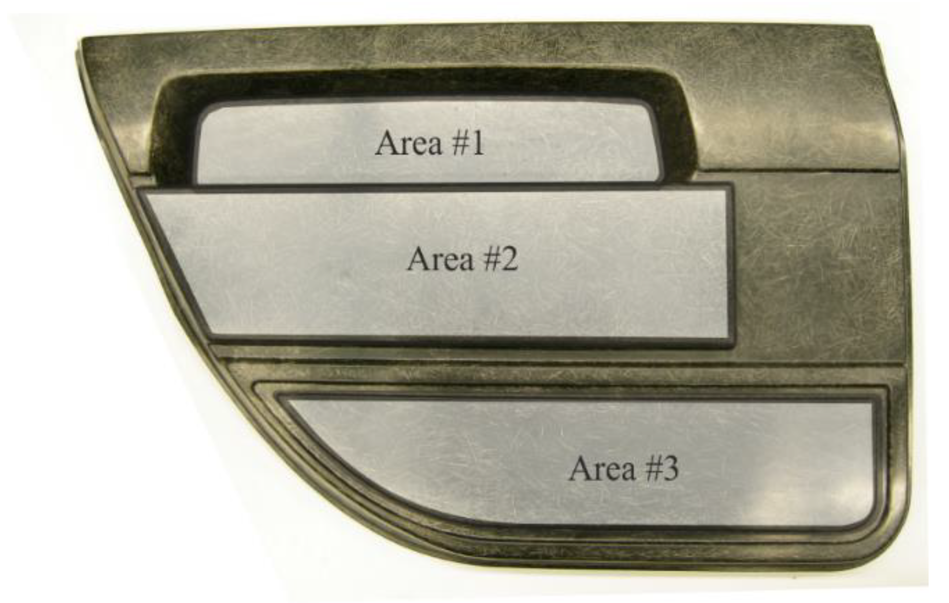
The three favorable areas investigated in the simulation section allow a meaningful integration of the piezoceramic transducers (
Figure 4). In the following section, the simulation results will be validated by the measurement of the surface velocities.
3.1. Preparation of a Test Setup
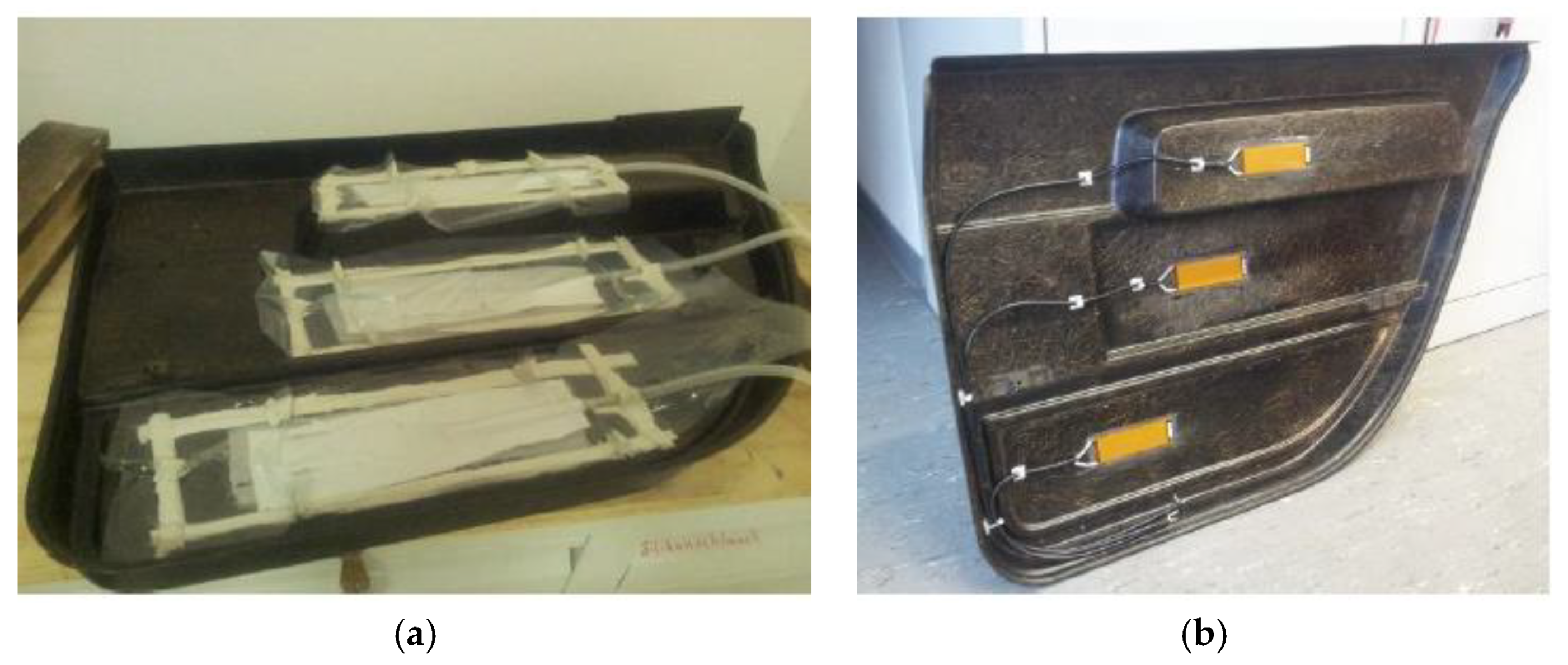
For the comparison of the three integration areas, piezo ceramic actuators (type M-8528-P1, Smart Material GmbH, Dresden, Germany) were integrated into each analyzed area. In contrast to the aimed final integration procedure, the piezo actuators were bonded to the back of the state-of-the-art side door panel (
Figure 5). The bonding was carried out in the VARI (vacuum-assisted resin infusion) process. Due to the negative pressure applied, the adhesive is evenly drawn through the mold and the entire component is evenly filled. The curing took place within 8 h at a temperature of 80 °C. For a defined bonding layer thickness of 0.2 mm, the adhesive was mixed with glass beads of defined diameter.
In order to enable a safe switching process between the individual piezo ceramics, these were soldered with BNC sockets.
Figure 5 shows a picture of the manufacturing process on the left side and the door panel with the bonded piezo ceramics on the right side.
3.2. Measurement of the Surface Velocity
In order to analyze the influence of the piezoceramics bonded in the three considered areas on the acoustic behavior of the side door panel the out-of-plane velocities—a physical quantity that can be treated as an indicator of sound radiation—were measured using laser scanning vibrometry technique.
Surface velocities were measured using a laser scanning vibrometer type PSV 400 (Polytec GmbH, Waldbronn, Germany). A periodic chirp signal with an amplitude of 200 V was used to drive the actuators. The high voltage was achieved using a high-voltage amplifier Trek Model 2205. The out-of-plane velocities were measured on 123 positions in a regular raster, as presented in
Figure 6.
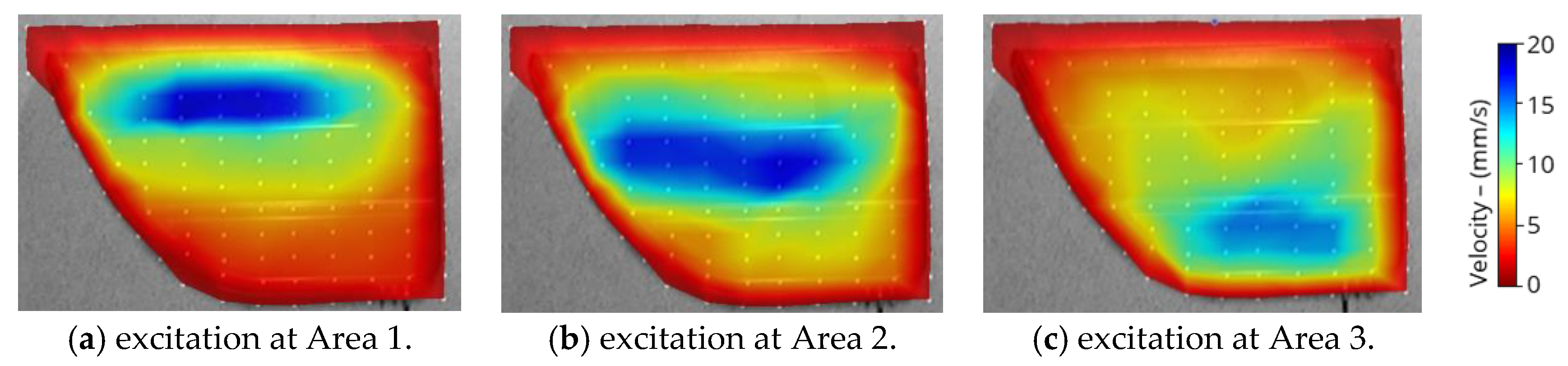
To improve the laser beam reflectivity, the measuring points were marked with a reflective foil, reducing the noise of the measurement signal and thus reducing the average error. The results of the measurements—in a form of a root-mean square—are presented for all three excitation positions in
Figure 7.
The excitation at area 1 and area 2 have a similar nature and can create local radiation by the effect of high mechanical impedance change towards the main structure. The excitation at area 3 spreads over large parts of the structure and due to the high interference density, the overall out-of-plane velocity is lower.
The presented results are in good accordance with the simulated velocities (
Figure 3). The minor differences result from the excitation, which is simulated as point force, which occurs over a larger area in reality. The conclusions from the preliminary design have been confirmed.
3.3. Preliminary Conclusion
The piezoceramics in the upper part of the door panel enable a high acoustic impedance jump to the surrounding structural parts due to the stiffening effect of the bead and thus enables uniform sound radiation with low interference effects. While exciting at area #1 exhibits concentrated sound radiation, an excitation in area #2 or #3 leads to the formation of secondary sound sources or a complete spread over the entire structure, and thus form strong interference spectra. Hence, in order to maintain as clear sound as possible, the integration area of the piezoelectric transducers in further studies is selected to be the area #1.
4. Manufacturing of a Car Door with Integrated Flat Panel Loudspeaker
The active door side panel is manufactured using the long fiber injection process, a fully automated polyurethane spraying process which is characterized by the processing of two-component reactive polyurethane (PUR) systems. By means of a high-pressure dosing machine and mixing head, the polyurethane mixture is discharged simultaneously with chopped glass fibers into an open mold. During the spraying process, both the fiber length and the fiber mass content can be varied locally. Within this study, an expanding PUR-system is used, whose components, polyol and isocyanate, are processed in the mixing ratio of 100/215.
The used mold is made of steel and tempered by means of water to a temperature of 70 °C. After the spraying process, the lower mold is transferred by means of a shuttle into the mold carrier, where it is closed. In the closed mold, the glass fiber-polyurethane mixture expands and cures. The curing time of the used polyurethane system is approx. 6 min. Process parameters like fiber mass content and composite density were set to meet the characteristic values assumed in the design.
For the later characterizations, three different specifications of the door panel were manufactured, which differ in the type of reinforcement in the membrane area. All specifications are shown in
Figure 8. Specification A corresponds to the state of the art; here, the complete panel was manufactured with a fiber mass content of 30% and a fiber length of 25 mm without additional reinforcement. In specification B, the area of the membrane was made without reinforcing fibers. For this purpose, the cutting unit of the LFI mixing head was deactivated. In specification C, a textile reinforcing structure is integrated in the region of the membrane. Based on preliminary studies on the impregnation of textile semi-finished reinforcements, a carbon fiber fabric with satin weave and a grammage of 165 g/m
2 was chosen.
For the implementation of the active fiber composite structure, the development of suitable solutions for the reproducible integration of the piezoceramic actuator, the textile reinforcement and the connection cables are of special importance (see also [
23]). The focus here was on the exact placement of the actuator, since a constant position is required for the following acoustic characterizations.
Despite the low structural rigidity of the thin connection cables, the positioning of the actuator is influenced when it is connected to the cables. Furthermore, as a result of the spraying process, a displacement or rotation of the actuator may occur. In order to ensure a reproducible position of the actuator, this is therefore locally fixed on the mold cavity by means of a fast-curing adhesive. This method has proved to be advantageous over other fixing methods that have also been studied, and it is also used for fixing the connection cables in the mold;
Figure 9.
When producing the specification with textile reinforcement, the piezoelectric actuator is placed on the fabric. After the components have been positioned in the mold, the assembly gets backfoamed with the glass-fiber polyurethane mixture. As a result of the expansion process during curing, the fabric is infiltrated with the PUR matrix, creating a continuous fiber-reinforced composite in this area,
Figure 10b.
5. Validating Tests of the Final Design
This section analyzes the range of properties achieved in the LFI-manufacturing process and their influence on the acoustic behavior. Furthermore, recommendations for specific material properties and construction details of a piezo-ceramic driven flat-panel loudspeaker are given. For the acoustical measurement, a system consisting of a microphone type 2669, a power supply module type 2826, an input module type 3041 and a controller module type 7540-A by Bruel and Kjaer were selected. The microphone was placed in 1 m distance of the structure focusing toward the center of the panel (see
Figure 11).
The results of the individual pressure level of each specification are shown in the following
Figure 12. The results are smoothed with 1/3 per octave to increase comparability due to the high deviation of the frequency response. As shown in
Figure 12, all three specifications have different frequency-dependent behavior, which illustrates the property range of the manufacturing process. All specifications have a lower frequency limit of approx. 300 Hz, which corresponds to a midrange/tweeter driver. This frequency limit is the result of the small radiating area, which gives a sufficient decoupling, but an increased stiffness for low-frequency radiation. For the full frequency reproduction, an additional woofer is needed.
The reached acoustical properties are summarized in
Table 1 and expressed with the following parameters: lowest frequency, mean sound pressure level (SPL) and frequency deviations.
Specifications A and B have nearly similar mean SPL, whereby specification B is with 76.2 dB, the most sensitive one, which corresponds to the lower mass and lower stiffness of the membrane. Furthermore, specification B has the lowest frequency limit, with 300 Hz. Through the soft membrane, SPL difference at 100 Hz of approx. 20 dB is possible and the low-frequency behavior is improved. However, this specification has not only advantages. The deviation of specification B is much higher compared to specification A, which results in a more uneven frequency response and more DSP-filtering is needed.
Furthermore, similar deviation results are achieved by the stiffer specification C. This implicates a certain optimum of modal density for a given structure, defined by the area, ratio and material properties. In general, specification C is too stiff for this application. This results in a higher corner frequency of 393 Hz and a 6.5 dB lower mean SPL. This is the result of the higher mass, due to the additional reinforcement structure and the increased stiffness, which decreases the efficiency of the piezo-ceramic.
In summary, this section emphasized the variety of properties, which can be achieved with the LFI-manufacturing process. An actuator at one position can lead to significantly different acoustical properties depending on the type of integration. In this case, an unstiffened specification provides the lowest frequency and the highest sensitivity. The flattest behavior can be achieved with specification A and non-modified properties. A structure that is too stiff results in lower sensitivity and missing low-frequency level. Reinforcement is not recommended for this speaker configuration. In the following steps, the low-frequency behavior needs to be improved as well as the frequency deviation, to be more comparable to conventional speaker systems.
6. Discussion and Conclusions
This paper presents a piezoceramic driven loudspeaker for an automotive door side panel, which is characterized by low weight, low installation space, and a good possibility to integrate during the manufacturing process. The door side panel itself is manufactured using the long fiber injection (LFI) process, which gives possibilities to obtain various mechanical properties in the same component within the same production step. Despite their favorable characteristics, the application of structure-integrated flat panel loudspeakers is still connected, with many challenges. The lowest frequency limit and the non-flat frequency spectrum are especially noticeable. It could be shown that an actuator at one position can lead to significantly different acoustical properties depending on the type of integration. Depending on manufacturing properties, the flatness of the response could be achieved or the low-frequency performance and sensitivity can be improved. Additional reinforcement is not suggested at this stage. Generally, the usable range of structure-integrated flat panel loudspeakers analyzed within this paper starts at 300 Hz. Consequently, this design is predestined for a midrange/tweeter driver, which can be supported by a common woofer to cover the low frequencies. Linearizing flat panel loudspeakers with a DSP to increase the acoustical quality is recommended. Furthermore, it is useful to improve the linearity of the speaker in its original configuration by using bracing, new reinforcement combinations, and changes in the form factor. Besides, the radiation should be extended to lower frequencies, which is possible by increasing the vibrating membrane surface.
Potential applications of the proposed integrated, lightweight and space-saving loudspeaker would be, for example, the reproduction of warning signals or navigation instructions in vehicles without high-quality hi-fi equipment. In mechanical and plant engineering, for example, enclosures or plane panels could be functionalized, in order to make acoustic signals usable for warning or error messages in addition to the visual signals that are usually present. In order to achieve the desired effects, the boundary conditions resulting from the used material, the desired functionality and the manufacturing process must be taken into account during conceptual design, dimensioning and manufacturing, according to the presented approach.
Author Contributions
Conceptualization, M.D., B.Z. and S.G.; methodology, M.D. and B.Z.; validation, B.Z.; formal analysis, B.Z. and K.H.; investigation, B.Z. and O.W.; resources, N.M., S.G., M.E.A. and M.D.; data curation, B.Z.; writing—original draft preparation, K.H., M.D., S.G., and B.Z.; writing—review and editing, K.H., M.D., O.W. and N.M.; visualization, B.Z.; supervision, N.M., M.D., M.E.A. and S.G. All authors have read and agreed to the published version of the manuscript.
Funding
This research received no external funding.
Conflicts of Interest
The authors declare no conflict of interest.
References
- Cecchi, S.; Palestini, L.; Peretti, P.; Piazza, F.; Bettarelli, F.; Toppi, R. Automotive Audio Equalization. In Proceedings of the Audio Engineering Society Conference: 36th International Conference: Automotive Audio, Dearborn, MI, USA, 2–4 June 2009; Audio Engineering Society: Red Hook, NY, USA, 2009. [Google Scholar]
- Hasenberger, E.; Krump, G.; Schneider, M. Evaluating Binaural Simulations of a Premium Automotive Sound System. In Proceedings of the Audio Engineering Society Conference: 2019 AES International Conference on Automotive Audio, Neuburg an der Donau, Germany, 11–13 September 2019; Audio Engineering Society: Red Hook, NY, USA, 2019. [Google Scholar]
- Boehm, J.; Olszewski, D.; Mirza, Z.B.; Rathmann, P.; Prados-Vilchez, A.; Botan, V.; Binder, J.; Rodemer, K. A Distributed Audio System for Automotive Applications. In Audio Engineering Society Convention 144; Audio Engineering Society: Red Hook, NY, USA, 2018. [Google Scholar]
- Ceruti, D.; Guyader, G.; Lemarquand, G.; Remy, M.; Six, M.-F.; Toppi, R. Ironless Motor Loudspeaker: Quantization of the Subjective Enhanced Sound Quality. In Audio Engineering Society Convention 129; Audio Engineering Society: Red Hook, NY, USA, 2010. [Google Scholar]
- Zenker, B.; Merchel, S.; Altinsoy, M.E. Rethinking Flat Panel Loudspeakers—An Objective Acoustic Comparison of Different Speaker Categories. In Audio Engineering Society Convention 147; Audio Engineering Society: Red Hook, NY, USA, 2019. [Google Scholar]
- Schaefer, Patrick: “Soundsystem von Continental und Sennheiser ohne Lautsprecher”. Available online: https://www.springerprofessional.de/en/interieur/infotainment/soundsystem-von-continental-und-sennheiser-ohne-lautsprecher/17565486 (accessed on 20 January 2020).
- Schmetter, R.M. The Piezoelectric Loudspeaker: Its Use in Audio Systems. In Audio Engineering Society Convention 43; Audio Engineering Society: Red Hook, NY, USA, 1972. [Google Scholar]
- Klapholz, J. High Polymer Piezo Film in Electroacoustical Transducer Applications. In Audio Engineering Society Convention 79; Audio Engineering Society: Red Hook, NY, USA, 1985. [Google Scholar]
- Rumsey, F. Automotive Audio Optimization, Testing, and Evaluation. J. Audio Eng. Soc. 2019, 67, 814–818. [Google Scholar]
- Zenker, B.; Rawoof, S.S.A.; Merchel, S.; Altinsoy, E. Optimized Exciter Positioning Based on Acoustic Power of a Flat Panel Loudspeaker. In Audio Engineering Society Convention 146; Audio Engineering Society: Red Hook, NY, USA, 2019. [Google Scholar]
- Zenker, B.; Rawoof, S.S.A.; Merchel, S.; Altinsoy, M.E. Low Deviation and High Sensitivity—Optimized Exciter Positioning for Flat Panel Loudspeakers by Considering Averaged Sound Pressure Equalization. In Audio Engineering Society Convention 147; Audio Engineering Society: Red Hook, NY, USA, 2019. [Google Scholar]
- Kostka, P.; Holeczek, P.; Hufenbach, W. Structure-integrated active damping system: Integral strain-based design strategy for the optimal placement of functional elements. Int. J. Compos. Mater 2013, 3, 53–58. [Google Scholar]
- Younes, U. Recent Advances in Class “A” Polyurethane Long Fiber Injection (LFI) Composites. Automot. Plast. 2010, 39, 8–14. [Google Scholar]
- Stratton, D.; Platte, P.; Rocco, D. A Modular Automotive Roof System Design Concept Based on Polyurethane Composite Technology. In Proceedings of the 6th Annual SPE Automotive Composites Conference, Troy, MI, USA, 12–14 September 2006; pp. 475–491. [Google Scholar]
- Renkl, J.; Söchtig, W. LFI-PUR—The Process for High-Quality, Long-Glass-Fiber-Reinforced Polyurethane Parts. In Proceedings of the 5th Annual SPE Automotive Composites Conference, Troy, MI, USA, 12–14 September 2005. on CD. [Google Scholar]
- Starke, J.; Peters, F.; Mätzig, S. LFI-PUR A Process Gains Acceptance and Opens up New Possibilities. In Proceedings of the International Polyurethanes Conference & Exhibition for Asia-Pacific UTECH Asia ’99, Suntec City, Singapore, 16–18 March 1999. Automotive Paper 6. [Google Scholar]
- Geller, S.; Tyczynski, T.; Gude, M.; Sauer, S.; Fischer, W.-J. Glass fiber-reinforced polyurethane composite structures with integrated piezoelectric sensor elements and corresponding electronics. Adv. Eng. Mater 2018, 20, 1800447. [Google Scholar] [CrossRef]
- Geller, S.; Winkler, A.; Gude, M. Investigations on the structural integrity and functional capability of embedded piezoelectric modules. In Proceedings of the 6th International Conference on Emerging Technologies in Non-destructive Testing ETNDT6, Brussel, Belgium, 27–29 May 2015; CRC Press: London, UK, 2016; pp. 361–365. [Google Scholar]
- Frehsdorf, W.; Söchtig, W. High Requirements—Low Investment Costs. Kunst.-Plast Eur. 2001, 3, 23–25. [Google Scholar]
- Serban, D.-A.; Weissenborn, O.; Geller, S.; Marsavina, L.; Gude, M. Evaluation of the mechanical and morphological properties of long fibre reinforced polyurethane rigid foams. Polym. Test. 2016, 49, 121–127. [Google Scholar] [CrossRef]
- Wave6, “Software version 2019.11.2”, Dassault Systemes SIMULIA Corporation. Available online: www.wavesix.com (accessed on 20 February 2019).
- Fahy, F.; Gardonio, P. Sound and Structural Vibration. Radiation, Transmission and Response, 2nd ed.; Elsevier/Academic: Amsterdam, The Netherlands; London, UK, 2007; pp. 40–50. ISBN 978-0-12-373633-8. [Google Scholar]
- Dannemann, M.; Holeczek, K.; Modler, N.; Winkler, A.; Starke, E.; Weiß, M.; Rupitsch, S. Development of Material-Integrated Actuator-Sensor-Arrays for Obstacle Sensing. Adv. Eng. Mater. 2018, 20, 1800475. [Google Scholar] [CrossRef]
Figure 1.
Convergence analysis of the error , calculated as the difference of the solved eigenfrequencies of a reference mesh, with an element length of 2.5 mm and the results of different mesh sizes. It could be shown that the used element length of 9 mm occurs with an error of less than 1%.
Figure 1.
Convergence analysis of the error , calculated as the difference of the solved eigenfrequencies of a reference mesh, with an element length of 2.5 mm and the results of different mesh sizes. It could be shown that the used element length of 9 mm occurs with an error of less than 1%.
Figure 2.
FE simulation model based on a CAD model meshed with CQUAD8 Elements and with fixed constraints on the free edges; (a) the frontside of the panel, (b) the backside with individual point forces, and (c) the cross-section with individual structure depths marked red.
Figure 2.
FE simulation model based on a CAD model meshed with CQUAD8 Elements and with fixed constraints on the free edges; (a) the frontside of the panel, (b) the backside with individual point forces, and (c) the cross-section with individual structure depths marked red.
Figure 3.
Surface velocity in the frequency range of 500 Hz to 5 kHz according to Equation (4) at three possible excitation locations: (a) area 1, (b) area 2, and (c) area 3.
Figure 3.
Surface velocity in the frequency range of 500 Hz to 5 kHz according to Equation (4) at three possible excitation locations: (a) area 1, (b) area 2, and (c) area 3.
Figure 4.
Integration areas in the car door panel.
Figure 4.
Integration areas in the car door panel.
Figure 5.
(a) Production setup of the secondary bonding process, and (b) finished component.
Figure 5.
(a) Production setup of the secondary bonding process, and (b) finished component.
Figure 6.
Image of the side door panel with marked positions of the measuring points.
Figure 6.
Image of the side door panel with marked positions of the measuring points.
Figure 7.
Measured averaged out-of-plane velocities (RMS values) in the frequency range between 818 Hz and 10.3 kHz for the excitation using the integrated piezoceramic transducers in the following areas: (a) Area 1, (b) Area 2, and (c) Area 3.
Figure 7.
Measured averaged out-of-plane velocities (RMS values) in the frequency range between 818 Hz and 10.3 kHz for the excitation using the integrated piezoceramic transducers in the following areas: (a) Area 1, (b) Area 2, and (c) Area 3.
Figure 8.
Definition of three different manufacture specifications of the door panel. (a) represents a structure without additional changes, (b) without any reinforcement, and (c) a structure with carbon fiber reinforcement.
Figure 8.
Definition of three different manufacture specifications of the door panel. (a) represents a structure without additional changes, (b) without any reinforcement, and (c) a structure with carbon fiber reinforcement.
Figure 9.
(a) Local fixation of the piezoelectric actuator, and (b) connecting cables in the mold cavity by means of a fast curing adhesive.
Figure 9.
(a) Local fixation of the piezoelectric actuator, and (b) connecting cables in the mold cavity by means of a fast curing adhesive.
Figure 10.
(a) Piezoelectric actuator placed on the carbon fabric just before embedding, and (b) textile-reinforced composite after curing.
Figure 10.
(a) Piezoelectric actuator placed on the carbon fabric just before embedding, and (b) textile-reinforced composite after curing.
Figure 11.
Microphone placed in 1 m distance to the panel.
Figure 11.
Microphone placed in 1 m distance to the panel.
Figure 12.
Comparison of the individual sound pressure levels of all three specifications: A—standard configuration, B—without additional reinforcement, C—with local carbon fiber reinforcement.
Figure 12.
Comparison of the individual sound pressure levels of all three specifications: A—standard configuration, B—without additional reinforcement, C—with local carbon fiber reinforcement.
Table 1.
Evaluation of the following properties mean SPL, lower frequency limit and the logarithmic standard deviation of all three specifications Area1—A–C.
Table 1.
Evaluation of the following properties mean SPL, lower frequency limit and the logarithmic standard deviation of all three specifications Area1—A–C.
| Properties | Area1—A | Area1—B | Area1—C |
|---|
| (500 Hz–5 kHz) [dB] | 74.51 | 76.20 | 69.68 |
| (−10 db) [Hz] | 330.6 | 303.1 | 393.1 |
| (300 Hz–10 kHz) [dB] | 4.95 | 9.16 | 9.16 |
© 2020 by the authors. Licensee MDPI, Basel, Switzerland. This article is an open access article distributed under the terms and conditions of the Creative Commons Attribution (CC BY) license (http://creativecommons.org/licenses/by/4.0/).


 ,
, 


