1. Introduction
With the recent widespread use of haptic devices [
1], better haptic performance and more efficient linear vibration motors are in high demand, particularly in smartphones, vehicle infotainment displays, and video game controllers. Numerous studies on linear vibration motors have been conducted. Lee et al. designed an integrated microspeaker and linear vibration motor, which showed better performances compared to the conventional type [
2]. A horizontal linear vibrating actuator was designed to reduce the thickness of a smartphone, which represents an improvement in haptic performance compared to a vertical linear vibration actuator [
3]. In addition, Nam et al. proposed a novel design of a linear actuator with a large magnetic force to reduce the response time without decreasing the vibration magnitude [
4]. A resonant piezoelectric vibrator was also designed by using a resonant amplification mechanism to have a high output displacement at a low frequency for haptic device applications [
5]. Most of these related studies have focused more on improving motor performance without considering the influence of the magnetic flux leakage when these devices have been applied.
A neodymium iron boron magnet has been widely used to obtain sufficient displacement. However, this produces strong magnetic flux leakage, which has a harmful effect on passengers who have a cardiac pacemaker or an ICD (implantable cardioverter defibrillator). The strong magnetic flux leakage may damage these medical devices and cause life-threatening malfunction [
6]. According to the engineering specification when considering the above situation, the magnetic flux leakage requirement at the measurement point should be under 50 G. Furthermore, metallic dirt can easily be collected on the vehicle LCD display due to magnetic flux leakage, creating an uncomfortable experience for people using a haptic device. It is therefore necessary to reduce the magnetic flux leakage while maintaining the same performance. The motor performance requirements were decided by previous research [
7,
8] with consideration for the human mechanoreceptors that are the nerve endings in the skin responsible for sensitivity to vibration and pressure [
9]. The maximum displacement of a linear vibration motor is around 0.4 mm, and the range of resonance frequency is from 138 Hz to 150 Hz, while the working frequency is from 50 Hz to 500 Hz, and the electrical resistance is around 8 ohms. These requirements are enough for haptic feedback to users.
The magnetic flux leakage calculation [
10,
11] used for the 3D finite element method is employed to obtain the magnetic flux leakage at a certain measurement point. The voltage equation and the equation of motion are used to obtain the displacement and the impedance by considering the electromagnetic-mechanical coupling: these parameters indicate the performance of a linear vibration motor. The analysis results of the prototype were analyzed and verified based on the experimental results. The experimental results satisfied the motor performance requirements except for the magnetic flux leakage.
Three types of new designs were proposed to reduce magnetic flux leakage. The first design attempted to reduce the magnet source and magnetic flux conducting path, which included the magnet grade, the magnet thickness, and the top plate thickness. However, the analysis results of the first design were unacceptable owing to the high magnetic flux leakage exceeding 50 G. To reduce the magnetic flux leakage as much as possible, the second design was developed by reversing the prototype with a lower magnet grade and a thicker top plate, limiting the reduction on the force factor to less than 5%. The second design had a new plate, a protector, and two inserted plates. There was an 87.09% reduction between the second design and the prototype without much reduction in the force factor. Then, the second design with the shielding plate was employed as the final design, which achieved the maximum reduction in terms of magnetic flux leakage by applying magnetic shielding [
12]. Two types of experimental set-ups were used to obtain the experimental results. One is the Kanetec Gauss meter (TM-701) to obtain the experimental magnetic flux leakage, the other is the Klippel equipment to obtain the displacement and impedance of a linear vibration motor. The analysis results were verified experimentally.
2. Prototype Modeling
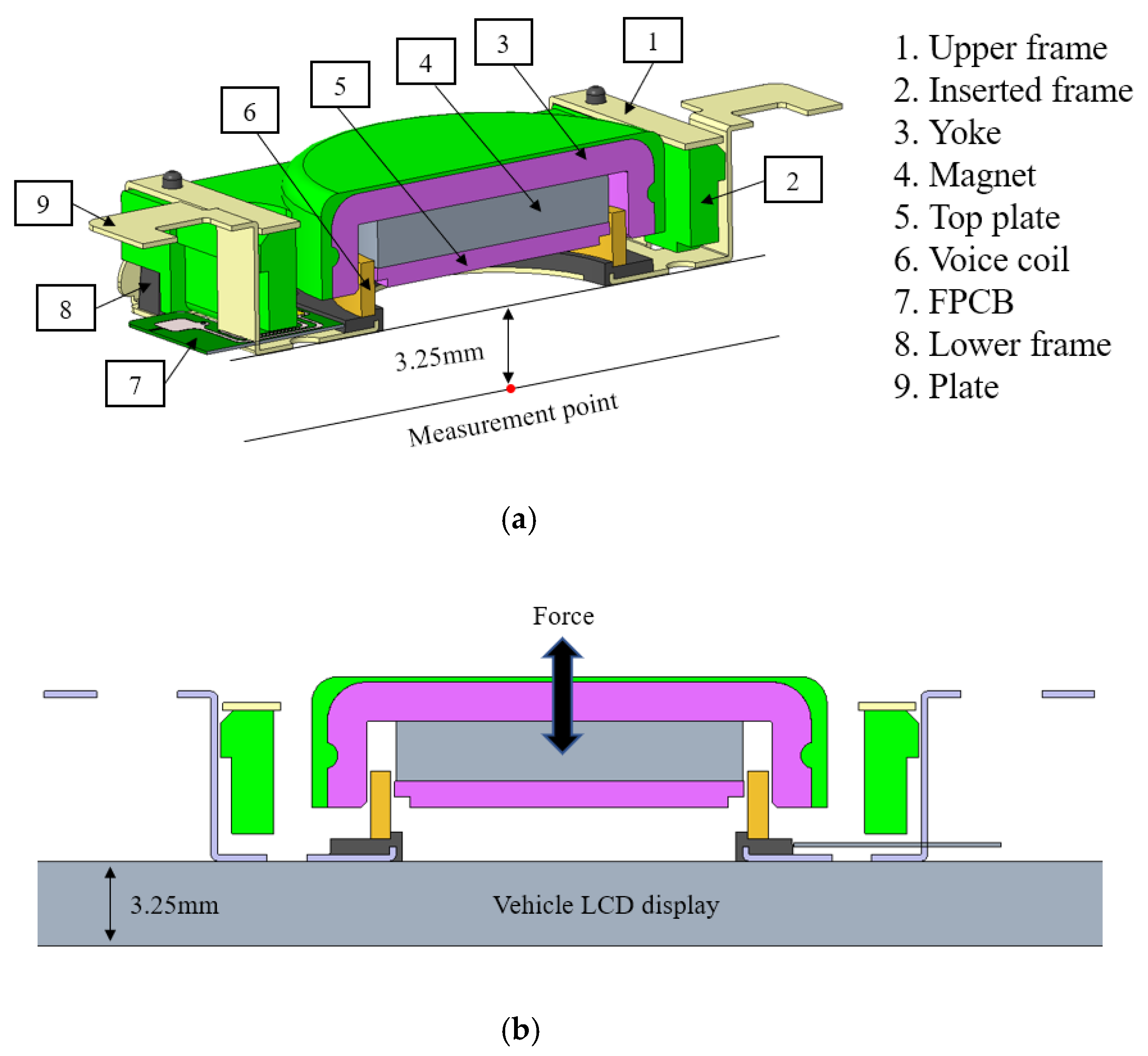
A linear vibration motor includes an electromagnetic system and a mechanical vibration system. The electromagnetic system has a voice coil, a top plate, a magnet, and a yoke. The mechanical vibration system consists of an inserted frame, an upper frame, a lower frame, and a plate. The thickness of the vehicle LCD display is 3.25 mm. The prototype of the linear vibration motor and measurement point are shown in
Figure 1.
In linear vibration motors, the voice coil remains stationary. The other magnetic parts (top plate, magnet, and yoke) and the inserted frame become a movable mass, in which the inserted frame is treated as a spring. As the working principle, the linear vibration motor creates a Lorentz force by using the Fleming left-hand rule, which drives the movable mass up and down to obtain the displacement owing to the AC driving signal. The displacement is transferred to the touch screen to allow people to feel haptic feedback. The magnetic flux leakage is defined as the magnetic flux that does not pass through the air gaps of the voice coil or other parts of the electromagnetic system.
The mechanical material properties of the linear vibration motor include the density, Young’s modulus, and Poisson’s ratio, which are shown in
Table 1. A neodymium iron boron (N48H) magnet, which is widely used in high-performance motors and micro-speakers, was applied; the remanence, coercivity, and relative permeability of the magnet were 14,000 G, 1046 kA/m, and 1.07, respectively.
The material name of the yoke is cold-rolled carbon steel sheets (SPCC), and the material name of the upper frame is stainless steel (SUS). The B-H curve is the curve characteristic of the magnetic properties of a material.
The SPCC B-H and SUS 430 B-H curves are shown in
Figure 2. The FPCB did not affect the analysis results and has been removed.
3. Analysis Methods
3.1. Magnetic Flux Leakage Calculation
For static magnetic fields, the magnetic flux density and magnetic flux leakage can be obtained using the 3D finite element method, via the following equations.
where
J,
H, and
B, are the current density, magnetic field strength, and magnetic flux density, respectively, and
μr is the relative permeability and
μ0 is the vacuum permeability.
For some of the materials, the relationship between
B and
H exhibits both non-linearity and hysteresis, in which
B is not a single-valued function of
H, but also depends on the history of the magnetization. It is useful to consider the incremental permeability, which is defined as follows:
This is called the B-H curve, the slope of which indicates the permeability of the material. In this analysis, only electromagnetic parts are needed, such as a yoke, a top plate, a magnet, and a voice coil. After solving the equations, the magnetic flux density for every node in the modeling can be obtained.
3.2. Linear Vibration Motor Performances
In the electromagnetic domain, the voltage equation can be expressed as follows:
where
Vinput,
i, and
R are the input voltage, current flowing in the voice coil, and direct current resistance of the voice coil, respectively. In addition,
Vback is the back electromotive force, which is determined by the velocity in the mechanical domain, and
Z is defined as the electrical impedance.
In the mechanical domain, the displacement of the inserted frame under an electromagnetic force is calculated using the finite element method. The entire model is discretized using elements, and the force equations on each node are established. The equation of motion in matrix form is expressed as follows:
where [
M], [
C], [
K], and {
F} are the mass, damping, stiffness matrices, and force vector, respectively, and
represents the displacement vector of all nodes.
The coupling between the electromagnetic and mechanical domains is described as follows: the permanent magnet acts as the magnetic source, and the yoke and top plate are used to conduct the magnetic flux. A voice coil is inserted into the magnetic circuit. According to the Fleming left-hand rule, with the horizontal magnetic flux and current, the movable mass will vibrate in the vertical direction owing to the Lorentz force. At the same time, the back electromotive force appears in the opposite direction to the current flow as a result of the movement of the movable mass relative to the electromagnetic domain. Thus, the relationships are written as follows:
where
l,
Bl, and
are the total voice coil length, force factor, and velocity of the movable mass, respectively. Based on the above equations, the displacement and impedance are obtained.
4. Results and Discussion
4.1. Prototype
Two experiments were conducted to verify the analysis results. The first one was a magnetic flux leakage measurement using a Kanetec Gauss meter (TM-701); the experimental set-up is shown in
Figure 3.
The second experiment involved the displacement and impedance of the linear vibration motor measured using Klippel equipment, a laser-based system that enables highly precise measurement. It included the power amplifier (PLX 1802), the distortion analyzer 2 (H1-DA2), the Klippel motor control, the computer, and the laser scanner. After applying the voltage to the linear vibration motor, the displacement could be detected by a laser, which depended on the frequency. In addition, according to the current sensor, the impedance was calculated by dividing the measurement current by the applied voltage. The set-up of the Klippel equipment is shown in
Figure 4.
Based on the analysis methods, the analysis results of the prototype showed that the magnetic flux leakage at the measurement point was 643.7 G, which was only 1.05% different from the experimental result (637.0 G), as shown in
Figure 5. The displacement and impedance obtained from the analysis results matched well with those obtained via the experimental results, as shown in
Figure 6. The experiment results satisfied the motor performance requirements except for the magnetic flux leakage requirement. Thus, the analysis methods could be used to design a new linear vibration motor.
By using the same analysis methods, three new designs were analyzed by comparing the force factor and the magnetic flux leakage. In a linear mechanical system, there is a linear relationship between the exciting force and displacement. The force factor can be used to represent the excitation force. The total coil length of the prototype was 4.97 m. The target value of the magnetic flux leakage was less than 50 G, maintaining the same performance as the prototype.
4.2. First Design
The first design aimed to change the magnet source and magnetic flux conducting path. There were three approaches as follows:
4.2.1. Changing Magnet Grade
The magnet grade of the prototype was N48H, although there were several magnet grades of lower than N48H, including N45H, N42H, and N40H. Therefore, the electromagnetic material properties of different magnets and analysis results are shown in
Table 2. The force factor and magnetic flux leakage are shown in
Figure 7.
With a decrease in the magnet grade, the magnetic flux leakage reduced linearly. However, the force factor also decreased. Compared to the prototype, there was a 15.40% decrease in magnetic flux leakage and an 11.86% decrease in the force factor when using an N35H magnet.
4.2.2. Changing Thickness of Top Plate and Magnet
The thickness of the top plate and the magnet of the prototype are 1.00 and 2.30 mm, respectively. Owing to the limited inner space of the linear vibration motor, the total thickness of the top plate and magnet is maintained. The analysis results with different top plate thicknesses are shown in
Table 3.
With an increase in the top plate thickness, the magnetic flux leakage reduced without a significant reduction in the force factor. This was because the thicker top plate could allow more magnetic fluxes to pass through, whereas the flux was reduced by a thinner magnet.
4.2.3. Punching Holes in the Top Plate and Magnet
Xu et al. [
13] presented a new way to reduce the magnetic flux leakage on the microspeaker by punching circular holes into a magnetic circuit. In their study, there were holes punched in the inner plate and inner magnet, which were the main parts of the microspeaker’s magnetic circuit. In the same way, the holes were punched in the top plate and in the magnet of the linear vibration motor. The analysis results according to different hole diameters are shown in
Table 4.
Moreover, the analysis results of the force factor and the magnetic flux leakage with different hole diameters are shown in
Figure 8. The force factor and the magnetic flux leakage decreased as the hole diameter increased.
With the three approaches, the most significant reduction of the magnetic flux leakage is 15.40% when using an N35H magnet. The second-best reduction occurs with a 4.00 mm hole diameter in the top plate and magnet, where the magnetic flux leakage reduces by 13.36%. However, neither are acceptable results owing to a force factor reduction of 11.86% and 6.41%, respectively. The least reduction occurs in the case with a top plate (1.20 mm) and a magnet (2.10 mm), in which there is only a 10.28% reduction of the magnetic flux leakage with a 1.60% reduction in the force factor.
However, these analysis results are still much higher than those at 50 G. Thus, other designs should be considered to obtain a greater magnetic flux reduction. To minimize the magnetic flux leakage and limit the reduction on the force factor to less than 5%, the lower magnet grade (N45H) and the top plate thickness (1.10 mm) are applied to the next designs.
4.3. Second Design
The second design method was a reverse structure of the prototype with an N45H magnet and a thicker top plate. At the same time, the protector was designed to fix and protect the voice coil instead of the lower frame. A new-shaped plate and two inserted plates were developed to connect to the vehicle LCD display. The material properties of the protector and the inserted plates were the same as the lower frame of the prototype.
The measurement position of the second design was the center point distancing 3.25 mm from the plate. The structural comparison between the prototype and the second design model is shown in
Figure 9.
The magnetic flux line and analysis results in terms of the magnetic flux leakage between the prototype and the second design are shown in
Figure 10 and
Table 5, respectively. From the comparison of the magnetic flux line, it is evident that the magnetic flux leakage of the second design is much smaller than that of the prototype. Compared to the prototype, the second design exhibits an 87.09% reduction in magnetic flux leakage with slight changes in force factor.
Furthermore, the development results of the second design included the magnetic flux leakage, displacement, and impedance. There was only a 1.31% difference between the analysis results (83.1 G) and the experimental results (82.0 G) with respect to the magnetic flux leakage. A comparison between the experimental results of the displacement and impedance between the prototype and second design is shown in
Figure 11. The analysis results of the second design showed good agreement with the experimental results. However, the magnetic flux leakage of the second design was still higher than 50 G.
4.4. Final Design
In order to isolate the effect of the magnetic field, different magnetic-shielding techniques have been applied. For static fields, the most important mechanism is magnetic flux shunting, using a high permeability magnetic material [
14,
15], as shown in
Figure 12.
Based on the second design, the final design is proposed to reduce the magnetic flux leakage as much as possible. A 2 mm thin plate made of SUS 430 is attached to the plate. The mechanical material properties and the B-H curve are shown in
Table 1 and
Figure 3, respectively. The final design modeling is shown in
Figure 13.
A comparison of the magnetic flux line between the second design and the final design is shown in
Figure 14. The permanent magnet generates the magnetic fluxes, which are passing through the magnetic circuit and the air. Most of the magnetic fluxes are concentrated on the yoke due to its high magnetic permeability, however, there are many magnetic fluxes that cannot return to the magnetic circuit, which lead to high magnetic flux leakage. When the high magnetic permeability plate (SUS 430) is added under the yoke, it creates the new magnetic circuit to make magnetic fluxes in the air return to the yoke.
Compared to the second design (3.01 N/A), the final design caused a 3.07% increase in the force factor due to the added plate. Furthermore, the magnetic flux leakage decreased by 93.07%, from 643.7 to 44.6 G, with a slight increase in the force factor, as shown in
Table 6.
The analysis results of the final design were verified based on the experimental results, which include the magnetic flux leakage, displacement, and impedance, as shown in
Figure 15. There is only a 1.36% difference in the magnetic flux leakage between the analysis and experimental results. The final design result shows a magnetic flux leakage of lower than 50 G.
5. Conclusions
In this study, the magnetic flux leakage and the force factor of a linear vibration motor were analyzed using a magnetic flux leakage calculation via the 3D finite element method. The displacement and impedance were confirmed using the electromagnetic-mechanical coupling method. Two experiments were conducted to validate the analysis results of the prototype, which satisfied the motor performance requirements, except for the magnetic flux leakage. Therefore, three designs were proposed to reduce the magnetic flux leakage. Owing to the unacceptable results of the first design, a lower magnet grade and a thicker top plate were applied to the second design, which developed a new structure of the linear vibration motor. The analysis of the second design showed the same performance as the prototype, but with a significant reduction (87.09%) in the magnetic flux leakage. Furthermore, the final design showed a maximum reduction of 93.07% in the magnetic flux leakage, when using magnetic shielding, and the magnetic flux leakage was lower than 50 G. Consequently, in this paper, a new design of a linear vibration motor was proposed to reduce the magnetic flux leakage, to be used for the in-vehicle infotainment in consideration of passengers who have a cardiac pacemaker or an implantable cardioverter defibrillator. A new linear vibration motor satisfied all the motor performance requirements. At the same time, this work provided an efficient method to predict the performance of a linear vibration motor. In addition, the linear vibration motor can also be used for the game controller to obtain a better gaming experience instead of the traditional rotation motor.
Author Contributions
Conceptualization, Z.-X.J., K.-H.P. and Prof. Hwang; methodology, Z.-X.J. and K.-H.P.; software, Z.-X.J. and K.-H.P.; validation, Z.-X.J. and K.-H.P.; investigation, Z.-X.J., K.-H.P., J.-H.K., Y.-W.J. and D.-P.X.; data curation, Z.-X.J. and K.-H.P.; writing—original draft preparation, Z.-X.J.; writing—review and editing, Z.-X.J., K.-H.P. and Prof. Hwang; visualization, Z.-X.J.; supervision, S.-M.H.; project administration, S.-M.H. All authors have read and agreed to the published version of the manuscript.
Funding
This research received no external funding.
Acknowledgments
This work was supported by a 2-Year Research Grant of Pusan National University.
Conflicts of Interest
No conflict of interest.
References
- Laycock, S.D.; Day, A.M. Recent developments and applications of haptic devices. Comput. Graph. Forum 2003, 22, 117–132. [Google Scholar] [CrossRef]
- Lee, H.J.; Hwang, S.M.; Hwang, G.Y.; Jeung, S.K.; Kang, B.S. Design of an integrated microspeaker and vibration motor used for mobile phones. J. Appl. Phys. 2003, 93, 8516–8518. [Google Scholar] [CrossRef]
- Lee, K.B.; Kim, J.H. Horizontal linear vibrating actuator to reduce smart phone thickness. J. Vibroeng. 2013, 15, 2003–2011. [Google Scholar]
- Nam, J.; Yeon, T.; Jang, G. Development of a linear vibration motor with fast response time for mobile phones. Microsyst. Technol. 2014, 20, 1505–1510. [Google Scholar] [CrossRef]
- Nam, J.; Kim, Y.; Jang, G. Resonant piezoelectric vibrator with high displacement at haptic frequency for smart devices. IEEE/ASME Trans. Mechatron. 2016, 21, 394–401. [Google Scholar] [CrossRef]
- Ziegelberger, G. ICNIRP Guidelines on limits of exposure to static magnetic fields. Health Phys. 2009, 96, 504–514. [Google Scholar]
- Kim, J.H.; Jiang, Y.W.; Hwang, S.M. Analysis and Design of New Actuator Used for Full-Wide Screen LCD. Appl. Sci. 2019, 9, 4599. [Google Scholar] [CrossRef] [Green Version]
- Kim, J.H.; Jiang, Y.W.; Hwang, S.M. Analysis of a vibrating motor considering electrical, magnetic, and mechanical coupling effect. Appl. Sci. 2019, 9, 1434. [Google Scholar] [CrossRef] [Green Version]
- Biswas, A.; Manivannan, M.; Srinivasan, M.A. Vibrotactile sensitivity threshold: Nonlinear stochastic mechanotransduction model of the Pacinian corpuscle. IEEE Trans. Haptics 2014, 8, 102–113. [Google Scholar] [CrossRef] [PubMed] [Green Version]
- Jin, J.M. The Finite Element Method in Electromagnetics; John Wiley & Sons: New York, NY, USA, 1993. [Google Scholar]
- Popović, B.D. Introductory Engineering Electromagnetics; Addison-Wesley: Reading, MA, USA, 1971. [Google Scholar]
- Budker, D.; Romalis, M. Magnetic shieling. In Optical Magnetometry; Cambridge University Press: Cambridge, UK, 2007; pp. 225–248. [Google Scholar]
- Xu, D.-P.; Jiang, Y.W.; Lu, H.W.; Kwon, J.-H.; Hwang, S.-M. Circular Holes Punched in a Magnetic Circuit used in Microspeakers to Reduce Flux Leakage. J. Magn. 2016, 21, 387–392. [Google Scholar] [CrossRef] [Green Version]
- Rikitake, T. Magnetic and Electromagnetic Shielding; Springer Science & Business Media: Tokyo, Japan; Dordrecht, The Netherlands, 1987. [Google Scholar]
- Ishiyama, A.; Hirooka, H. Magnetic shielding for MRI superconducting magnets. IEEE Trans. Magn. 1991, 27, 1692–1695. [Google Scholar] [CrossRef]
Figure 1.
Prototype modeling: (a) the half modeling; (b) the two-dimensional view.
Figure 1.
Prototype modeling: (a) the half modeling; (b) the two-dimensional view.
Figure 2.
B-H curve of SPCC and SUS 430.
Figure 2.
B-H curve of SPCC and SUS 430.
Figure 3.
Set-up of Kanetec Gauss meter.
Figure 3.
Set-up of Kanetec Gauss meter.
Figure 4.
Set-up of Klippel equipment.
Figure 4.
Set-up of Klippel equipment.
Figure 5.
Magnetic flux leakage of the prototype: (a) analysis result; (b) experiment results.
Figure 5.
Magnetic flux leakage of the prototype: (a) analysis result; (b) experiment results.
Figure 6.
Comparison between experiment and analysis results of the prototype: (a) displacement; (b) impedance.
Figure 6.
Comparison between experiment and analysis results of the prototype: (a) displacement; (b) impedance.
Figure 7.
Analysis results with changing magnet grade: (a) force factor; (b) flux leakage.
Figure 7.
Analysis results with changing magnet grade: (a) force factor; (b) flux leakage.
Figure 8.
Analysis results according to different hole diameters: (a) force factor and (b) magnetic flux leakage.
Figure 8.
Analysis results according to different hole diameters: (a) force factor and (b) magnetic flux leakage.
Figure 9.
Structural comparison between the prototype and the second design.
Figure 9.
Structural comparison between the prototype and the second design.
Figure 10.
Magnetic flux line: (a) prototype; (b) second design.
Figure 10.
Magnetic flux line: (a) prototype; (b) second design.
Figure 11.
Results of the second design: (a) magnetic flux leakage; (b) displacement; (c) impedance.
Figure 11.
Results of the second design: (a) magnetic flux leakage; (b) displacement; (c) impedance.
Figure 12.
Magnetic shielding: (a) without shielding; (b) with shielding.
Figure 12.
Magnetic shielding: (a) without shielding; (b) with shielding.
Figure 13.
Final design modeling.
Figure 13.
Final design modeling.
Figure 14.
Magnetic flux line: (a) second design; (b) final design.
Figure 14.
Magnetic flux line: (a) second design; (b) final design.
Figure 15.
Results of the final design: (a) magnetic flux leakage, (b) displacement; (c) impedance.
Figure 15.
Results of the final design: (a) magnetic flux leakage, (b) displacement; (c) impedance.
Table 1.
Mechanical material properties.
Table 1.
Mechanical material properties.
| Item | Material | Density [kg/m3] | Young’s Modulus [GPa] | Poisson’s Ratio |
|---|
| Yoke, top plate | SPCC | 7830 | 207 | 0.29 |
| Magnet | N48H | 2750 | 71 | 0.29 |
| Voice coil | Copper | 8960 | 110 | 0.34 |
| Upper frame, plate | SUS 301 3/4H | 7850 | 193 | 0.25 |
| Inserted frame | PVMQ | 1400 | 0.004 | 0.28 |
| Lower frame | Polycarbonate | 1200 | 221 | 0.25 |
| Shielding plate | SUS 430 | 7800 | 195 | 0.27 |
Table 2.
Analysis results with different magnet grades.
Table 2.
Analysis results with different magnet grades.
| Label | Magnet Grade | Remanence [G] | Coercivity [KA/m] | Force Factor [N/A] | Magnetic Flux Leakage [G] |
|---|
| 1 | N48H | 14,000 | 1046 | 3.12 | 643.7 |
| 2 | N45H | 13,500 | 1011 | 3.03 (−2.88%) | 619.2 (−3.81%) |
| 3 | N42H | 13,000 | 979 | 2.94 (−5.77%) | 594.4 (−7.66%) |
| 4 | N40H | 12,700 | 956 | 2.88 (−7.69%) | 579.4 (−9.99%) |
| 5 | N38H | 12,500 | 930 | 2.85 (−8.65%) | 569.5 (−11.53%) |
| 6 | N35H | 12,000 | 895 | 2.75 (−11.86%) | 544.6 (−15.40%) |
Table 3.
Analysis results with different top plate thicknesses.
Table 3.
Analysis results with different top plate thicknesses.
| Top Plate Thickness [mm] | Magnet Thickness [mm] | Force Factor [N/A] | Magnetic Flux Leakage [G] |
|---|
| 1.00 | 2.30 | 3.12 | 643.7 |
| 1.05 | 2.25 | 3.11 (−0.32%) | 626.6 (−2.66%) |
| 1.10 | 2.20 | 3.10 (−0.64%) | 608.2 (−5.51%) |
| 1.15 | 2.15 | 3.09 (−0.96%) | 592.9 (−7.89%) |
| 1.20 | 2.10 | 3.07 (−1.60%) | 577.5 (−10.28%) |
Table 4.
Analysis results with different hole diameters.
Table 4.
Analysis results with different hole diameters.
| Hole Diameter [mm] | Force Factor [N/A] | Magnetic Flux Leakage [G] |
|---|
| 0.00 | 3.12 | 643.7 |
| 0.50 | 3.11 (−0.32%) | 640.8 (−0.45%) |
| 1.00 | 3.10 (−0.64%) | 637.5 (−0.96%) |
| 1.50 | 3.09 (−0.96%) | 634.6 (−1.41%) |
| 2.00 | 3.07 (−1.60%) | 625.3 (−2.86%) |
| 2.50 | 3.04 (−2.56%) | 613.8 (−4.65%) |
| 3.00 | 3.01 (−3.53%) | 598.6 (−7.01%) |
| 3.50 | 2.97 (−4.81%) | 580.0 (−9.90%) |
| 4.00 | 2.92 (−6.41%) | 557.7 (−13.36%) |
Table 5.
Comparison of analysis results between the prototype and second design.
Table 5.
Comparison of analysis results between the prototype and second design.
| Type | Force Factor [N/A] | Magnetic Flux Leakage [G] |
|---|
| Prototype | 3.12 | 643.7 |
| The second design | 3.01(−3.40%) | 83.1 (−87.09%) |
Table 6.
Comparison of analysis results between the prototype and second design.
Table 6.
Comparison of analysis results between the prototype and second design.
| Type | Force Factor [N/A] | Magnetic Flux Leakage [G] |
|---|
| Prototype | 3.12 | 643.7 |
| The final design | 3.11 (−0.44%) | 44.6 (−93.07%) |
© 2020 by the authors. Licensee MDPI, Basel, Switzerland. This article is an open access article distributed under the terms and conditions of the Creative Commons Attribution (CC BY) license (http://creativecommons.org/licenses/by/4.0/).

 ,
, 


