Featured Application
Nowadays digital filters are widely used in receivers of different software-defined radio (SDR) communication systems. The main factor affecting the development of SDR is the characteristics of analog-to-digital and digital-to-analog converters. SDR technology allows us to replace existing and developed designs of receivers and transceivers of a heterodyne structure with a limited number of hardware units controlled by specialized software. This helps to simplify the constructions, make them cheaper, improve their performance, and support any modulation types. Furthermore, such an approach can be fruitful in signal reception and demodulation for different types of digital modulations such as DPSK, QAM, GMSK, etc. The main operations in the SDR receiver are heterodyning and filtering, which are performed digitally. In this case, digital filtering determines almost all parameters of the output channel of such a receiver. Therefore, the parameters of digital filters in these receivers have to meet more strict requirements, including the accuracy of calculations and hardware costs. The use of finite field algebra will significantly increase the accuracy of calculations in digital filters of such receivers and reduce hardware costs.
Abstract
The applications of digital filters based on finite field algebra codes require their conjugation with positional computing structures. Here arises the task of algorithms and structures developed for converting the positional notation codes to finite field algebra codes. The paper proposes a method for codes conversion that possesses several advantages over existing methods. The possibilities and benefits of optimization of the computational channel structure for digital filter functioning based on the codes of finite field algebra are shown. The modified structure of computational channel is introduced. It differs from the traditional structure by the fact that there is no explicit code converter in it. The main principle is that the “reference” values of input samples, which are free from the error of the analog-digital converter, are used as input samples. The proposed approach allows achieving a higher quality of signal processing in advanced digital filters.
1. Introduction
For the effective implementation of digital signal processing (DSP) algorithms, especially digital filters (DF), number-theoretic methods based on prime numbers [1,2,3] are of great importance. Many of these methods allow parallel computing, thus the research on theory and application of numerical systems with parallel structure is of particular interest in the field of DSP, image processing systems, cryptographic systems, quantum automated machines, neural computers systems, massive concurrency of operations, cloud computing, etc. [4,5,6,7,8,9]. Such systems are best suited for parallel computing. One of the most fruitful research areas here is the algebra of finite field, which provides an impressive level of internal parallelism [10] to the DSP systems.
Recent studies in designing DSP computing devices based on the finite field algebra (FFA) have shown that FFA has a superior potential for improvement of performance and reliability of numerical information processing being compared with the traditional positional numeral system (PNS) [11].
Since the FFA is an integer numeral system, it is possible to represent the processed data in DSP devices with arbitrary accuracy. From [11,12], it is known that the FFA advantages appear most clearly when tabular schemes are in use. Therefore, as the integral technology improves (e.g., the production of storage devices with high information density) along with the technical basis of the tabular computational method, efficiency of using FFA codes is steadily increasing.
Most popular designs of computing devices operating in FFA codes are focused on the implementation of computational processes of the same type despite their different specialization. These processes are the sequences of arithmetic operations (addition and multiplication) with integer numbers. This determines interest in researching the FFA implementation in highly efficient digital filtering algorithms. The following advantages of FFA can be outlined from [11,12,13]:
1. Independence of formation of numbers’ bits. Whereby each bit carries information about the entire original number instead of the intermediate number resulting from the formation of lower-order bits. This implies the possibility of numbers’ bits independent parallel processing.
2. The low bitness of residues representing a number. It results from a small number of possible code combinations. It allows using tabular arithmetic where the typical arithmetic operations are transformed into operations performed by simple selection of the result of calculations from the table (memory device).
3. The FFA has natural corrective abilities. The FFA codes allow efficient detection and correction of errors while transmitting signals and performing arithmetic operations [14].
Considering the abovementioned issues, we can conclude that it is advisable to use the FFA for the synthesis of DF with the required quality indicators. The FFA advantages compared with PNS allow providing the required frequency and accuracy characteristics of filters and digital signal processing in real-time [13]. Modern means of digital signal processing (for example, digital receivers) have strict requirements for the quality of signal processing. The analysis carried out in [12,13] showed that the use of FFA allows one to achieve the required indicators of signal processing quality. Let us give some preliminaries first.
2. The Basics of Operations on Numbers in the FFA
The theoretical basis of FFA is the theory of comparisons. Two integers, A1 and A2, that have the same residues being divided by module p are called comparable in modulus p, and the relation of comparability takes the following form:
From view of numbers comparability only residue α is used. It is obtained by dividing the number A by the number p. Thus, the following comparison is true:
Finding the residue is the transformation of the number A modulo p. The operation of determining the residue is performed by the following rule [11]:
The residues of number A modulo p will belong to the number range α ∈ (0, 1, 2, …, p − 1). While performing calculations it is always possible to replace the comparison that establishes a relationship between integer classes of numbers having the same residue with the equality including this residue. For example, if
Than Equation (4) can be written as follows:
Calculations with residues are rather simple since they can get values no more than p − 1 [11,12]. Therefore
Therefore, for any operations of multiplication, addition, subtraction, one can replace the result of calculations at each step by its residue. Representation of numbers in the FFA is provided by the smallest non-negative residues αi according to the system of mutually simple modules in the following form:
Addition, subtraction, and multiplication of two numbers A and B can be performed by the addition, subtraction, or multiplication of the residues αi and βi for each module pi, independently. If the value P is chosen as the product of modules pi, then actions with large numbers can be performed in such a system with a large number of small modules pi. The value P determines the complete range of representation of numbers in the FFA code.
The following identity can be written [11]:
where .
The identity (8) is the basis for generating the finite field arithmetic code. If the fixed series of positive integers p1, p2, …, pn are modules than the finite field arithmetic (the system of residual classes) is a such nonpositional number system in which any positive integer is represented as a set of residues from dividing the represented number by the selected base of the system as follows:
where α1, α2, …, αn—the smallest non-negative number residues by modules p1, p2 …, pn, respectively.
The numbers αi by the selected modules are formed as follows:
where A/pi—integer quotient; pi—bases-mutually prime numbers.
In number theory, it is proved [11,12] that if “i ≠ j, (pj, pi) = 1”, then the number representation (10) is the only one if 0 ≤ A ≤ Pn, where Pn = p1 · p2 · … · pn—is the number range, i.e., there is the number A for which
Thus, the conclusion can be done that is advisable to use the methods of organizing calculations based on the representation of the processed data in the FFA codes in the algorithms of digital filtering. It should be noticed that this task is solved on the basis of a systematic approach. Namely, for the synthesis of DF operating on the basis of the FFA codes a number of tasks should be solved including:
- -
- the task of converting the processed data from the positional representation to the FFA code. It requires the development of an efficient way of converting;
- -
- the task of converting the processed data represented in the FFA code to the positional representation. It requires the development of an efficient way of converting;
- -
- the task of implementation of the digital filtering algorithm in the FFA codes. The implemented algorithm should provide the required quality indicators of the filter output signal (accuracy, the calculation time of the output sample, reliability);
- -
- the task of providing the required degree of structural fault tolerance of the filter [15].
Currently, there are numerous studies devoted to solving the abovementioned tasks and other problems in DSP. Their solution will allow one to fully utilize the advantages of the FFA and ensure efficient signal processing in the digital filters [12,13]. In Figure 1, the variant of a simplified structural diagram of DF operating in the FFA codes is represented.
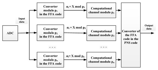
Figure 1.
The variant of simplified structural diagram of digital filters (DF) operating in the finite field algebra (FFA) codes.
3. Digital Filters in the FFA
Here we describe an implementation of the converter of position code to the FFA code. An opportunity to exclude an influence of the errors of analog-to-digital converter on the filter output sample is considered.
Analysis of the modern implementations of computational algorithms in the FFA codes allows concluding that the time of reverse conversion to positional representation in them takes more than 50% of the common time of calculations [11,12].
Insufficient development of the theoretical foundations of construction of code converters and, following this, the insufficient development of methods and means for their implementation becomes a critical place in the entire cycle of development and implementation of computing devices of DF operating on the basis of the FFA. It leads to loss of its advantages.
In [13,16,17] the algorithms of operation and hardware implementation of the devices for interfacing the positioning and computing FFA devices are reviewed. The devices in which the determination of residue is based on the use of the property of residues’ cyclical nature are considered. Following the Equation (1)
the residue αi will repeat d times in the range of convertible numbers. The cycle of its reiteration will depend on the value of module pi. In other words, the value d can be determined from the Equations (13) and (14).
where —is the residue of dividing the number by ; s—is the bit width of the number being converted in the FFA code. In accordance with the Equations (13) and (14) the residue corresponds to d numbers from the range of To calculate the residue of initial number A it should be uniquely determined that the number , i.e.,
For this goal the range of binary numbers presented in the FFA code can be divided into the subranges. The number of subranges and the values of numbers in them are determined by the value . The values of numbers in subranges will be within the numbers’ intervals with a step equal to one. They will be determined by the following expressions:
From the expression (15) it follows that the upper bits of number unambiguously determine the number of subrange in which the number is. While the lower bits of number A determines the index of number in the subrange. Thus, based on the cyclicity property of residues modulo, the finding of residue for the number A will include determination of subrange number and reading the residue from the memory device for each subrange. Considering the Equations (13)–(15), the algorithm of residue finding on the basis of subrange determination will include the following procedures:
- Determining the numbers subrange in the positional numeral system (PNS)
- Splitting the range into subranges (15).
- Determining the subrange by the upper bits of initial number A.
- Getting the residue from the memory device using the specific address by the lower bits of initial number A.
The block diagram of the proposed interfacing device includes the register where the initial number A is written, the comparison schemes and the memory devices. The proposed method of residue finding provides it for two modular cycles of the converter. The time of residue formation does not change with an increase in the bit width of the converted source numbers.
The disadvantage of the proposed algorithm is that the hardware costs required for its implementation are high. In addition, the residue values repeat in the memory devices. This indicates an incomplete use of modular code ring properties.
While researching the proposed algorithm of formation of a modulo residue it was found that the first values of residues in the subranges of expression (15) for the modules getting the values change by a value
while for the modules getting the values , these values are constant and determined as
Using these properties, the algorithm of residue determination can be described as follows:
where R—the number determined by the lower bits of the number A; —the value calculated using Equation (16) and written to the memory device (MD) by the address that gets the value in accordance with the upper bits of number A. The block diagram of the proposed converting device is provided in Figure 2.
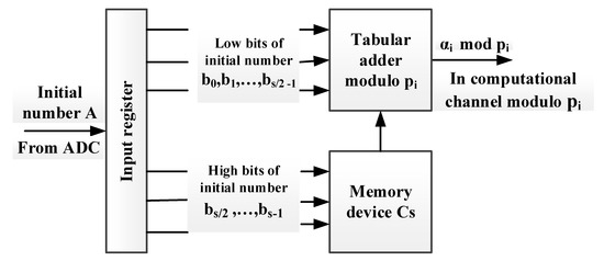
Figure 2.
The block diagram of the proposed converting device.
The developed algorithm provides the residue formation for three modular cycles of the interfacing device. Thus, we can conclude that the developed conversion method provides significantly better performance than the existing conversion methods considered in [10].
It should be noted that the algorithm provides operation in the conveyor mode, i.e., matching the speed of arrival of input data into the computing device of a DF and calculation of its output sample on the basis of FFA.
The abovementioned method of data representation in the FFA codes meets the requirements of the real-time signal processing devices in terms of performance indicators. Application of the conversion device for data in the FFA codes complicates the overall filter structure, requires additional costs to synchronize the operation of its elements in the mode of calculations conveyor. The question arises about the possibility of excluding the conversion device from the structure of the computation channel of DF to improve the accuracy of the calculation of the output sample.
In [15,16] the models of calculation accuracy for output samples in a positional digital filter and in the filter operating on the basis of FFA are provided. The model of calculation accuracy in the positional DF considering that while calculating the output sample the intermediate results will be rounded off, can be represented as follows:
where —the common calculation error for the output sample; —the error of analog-to-digital converter (ADC); —the error of coefficients quantization when they are represented in a computational digital filtering algorithm; —the error of input sample quantization when they are represented in a computational digital filtering algorithm; —the error introduced by the intermediate results rounding off; —the error resulting from the fact that the input of each subsequent stage will receive an intermediate sample, which already has an error that accumulates when the intermediate sample “passes” through the stages of the filter.
Moreover, the common model of calculation accuracy for an output sample in the positioning DF considering that the intermediate results will be truncated can be represented as follows:
where —the error introduced by truncation of intermediate calculation results in the filter links.
In the computational device of DF, operating on the basis of FFA, there is no such disadvantages as the operations of truncation (rounding off) of intermediate calculation results, the additional errors, the errors of quantification of input data and filter coefficients. Therefore, there is no accumulation of errors in the filter when calculating the output sample.
Then the accuracy model of output sample calculation for the DF operating on the basis of FFA can be represented as follows [14]:
Analysis of Equations (19)–(21) allows concluding that the accuracy of DF operating on the basis of FFA is significantly higher than the accuracy of positioning filters. Analysis of the influence of errors that occur when calculating the output sample of the FFA filter during signal processing in radio channels showed that the signal-to-noise ratio (SNR) is about 68–70 dB.
If the amplitude of the input signal is less than a half of the voltage of the full scale of ADC, then there is an additional attenuation about −20 dB. In this case, the SNR value is calculated as follows: SNR = 74 dB − 20 dB = 54 dB. However, as soon as radio channels are subject to significant fading, it can be argued that the SNR value will be 40–50 dB.
Thus, it can be concluded that in case of exclusion of ADC from the signal processing path, for example, from the digital receiver path (Figure 3 and Figure 4) the value of SNR can be increased.
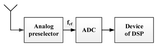
Figure 3.
The structure of digital receiver by radio frequency.
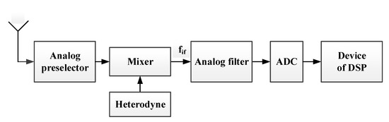
Figure 4.
The structure of digital receiver by intermediate frequency.
As soon as while building the digital receiver the range of data being processed in the digital signal processing device (Figure 3 and Figure 4) is known, namely, the bit width of used ADC is known, then there is an opportunity to represent input data being processed in the filters’ computational channel in the FFA codes without ADC and the device of their conversion. Considering Equation (12), the values of residues for any module of the selected base system do not exceed the value of the module and their count is equal to the module value. Then as a source of input data for the DF’s computational channel a memory device can be used. It records the values of residuals for the selected module.
Therefore, the FFA ring property allows one to significantly simplify the hardware implementation of the computing device of the filter, to increase its performance and to exclude the error of output sample calculation. Thus
In the case of such calculations, the error introduced by analog-to-digital conversion of input data is excluded from the channel of FFA digital filter. This further increases the accuracy of the calculation of the filter output sample. The structure of the computational channel of DF operating based on the FFA is shown in Figure 5.
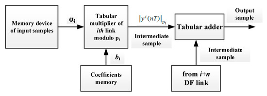
Figure 5.
The structure of the computational channel of DF operating based on the FFA.
Thus, the data converter from positional representation to the FFA code can be excluded from the DF structure. The ADC can be used as a control device for the selection of the required residue from the memory device of the output sample. In this case, one ADC can be used for all computational channels of the FFA DF.
4. Testing of DF in the FFA
Let us evaluate the proposed solutions experimentally. Evaluation of the efficiency of the proposed conversion method is conducted based on the comparison of its conversion time with the existing methods. Evaluation is made considering the number of operation cycles of comparable devices. It is provided in Table 1.

Table 1.
Comparative evaluation of performance of existing and developed conversion methods.
The data provided in Table 1 allows concluding that the proposed method for data conversion is efficient and can be used to build DF operating in the FFA codes.
The existing methods for data conversion from the positional representation to the FFA code are based on the sequential bitwise conversion of the source number. To get the modulo residue the arithmetic operations with the number bits are conducted. The type and the number of arithmetic operations depend on the conversion method. It determines the number of operation cycles for the conversion device (see Table 1).
Let the base system be given p1 = 5, p2 = 9, p3 = 13. The range of the processed data in this case is p = 585. In the case of this implementation, the DF structure will include three computational channels (see Figure 1). Each computational channel, except the computational device implementing the filtering algorithm, includes the data conversion device (see Figure 2).
In the considered case, when the conversion device is excluded from the structure of the calculation (Figure 5), in the memory device for the input sample, for example, modulo p2 = 9, the residue values for p = 585 will be recorded in the form of Table 2.
Table 2.
The residues values for the range p = 585 modulo p2 = 9.
Let us consider an example of a calculation of residue value for the number X = 32,015 modulo p = 17 for the method “Lowering the bit width with the parallel adder” (Table 1). Representing the number X = 32,015 in binary code and dividing it into blocks of 4 bits we obtain
i.e., we have 4 numbers a3 = 7, a2 = 13, a1 = 0, a0 = 15. Then we can write
X = 32015 = 0111 1101 0000 1111,
In the case of parallel implementation of this algorithm, the time of residue calculation is
where k—the block size (in the example k = 4); n = 16—the bit width of the input number X; tLUT—time of getting from the LUT-table (is taken equal to three cycles).
For the considered example, the time of residue calculation considering Equation (23) is equal to nine cycles, which corresponds to the Table 1.
To implement the considered converter (the number of hardware devices is brought to the amount of LUT-tables) eleven LUT-tables are required. For the suggested method (Figure 2), three LUT-tables are required. For the computational channel without conversion device (Figure 5), one LUT-table is required.
Following Equation (21), the error introduced to the processes signal by the twelve bit ADC is ∆ = 0.00024414. As an example, a non-recursive DF of the forty-fifth order is taken [13]. For evaluation the samples of impulse response of the filter taking values N1 = −0.000105023, N2 = −0.000125856, N17 = 0.0364568, N18 = 0.0328505 are selected. To simplify the provided values the sample sign of the impulse response is not considered and it is supposed that the ADC error decreases the values of the selected samples.
While calculating the output sample of the filter and representing the samples of impulse response in the binary code considering the ADC errors, their values can be written as follows: N1 = 0.000139117, N2 = 0.0001185284, N17 = 0.03621266, N18 = 0.03260636.
The values of samples of impulse response in the FFA code for the module p1 = 5 without error (in decimal notation and in FFA code) will be written as follows:
- N1 = (105023)10 = (3)FFA,
- N2 = (125856)10 = (1)FFA,
- N17 = (36456800)10 = (0)FFA,
- N18 = (32850500)10 = (0)FFA.
Considering the error introduced by the ADC, the values of samples of impulse response in the FFA code for the module p1 = 5 will be written (in decimal notation and in FFA code) as follows:
- N1 = (139117)10 = (2)FFA,
- N2 = (1185284)10 = (4)FFA,
- N17 = (362126600)10 = (0)FFA,
- N18 = (326063600)10 = (0)FFA.
As it follows from the conducted evaluation the values of the first and the second samples in the FFA code changed because of the ADC error influence. This error will change the filter frequency response in the process of calculation of its output sample. Considering that the error introduced by the ADC can affect the values of the significant number of impulse response samples, the distortion of frequency response will be significant.
5. Discussion
The known methods [18,19,20,21] for data conversion from the positional representation to the FFA code are based on the sequential bitwise conversion of the source number. To get the modulo residue the arithmetic operations with the number bits are conducted. The type and the number of arithmetic operations depend on the conversion method. It determines the number of operation cycles for the conversion device. Our study has shown that the data converter from positional representation to the FFA code can be excluded from the DF structure. In this case, the ADC can be used as a control device for the selection of the required residue from the memory device of the output sample. We described the structure of the computational channel and provided several practical tests, aimed both at a speed characteristics study and error estimation. The optimization technique was given and experimentally tested.
The obtained results open the possibility for efficient and compact hardware implementation of the digital filters on modern devices (DSP, FPGA, ASIC, etc.) for processing signals in various areas, such as radio communication, hydroacoustics, radars and echolocation systems, as well as in industry, defense, law enforcement, and other fields of science and technology [22]. Further research will be devoted to the comparison of the proposed approach with existing techniques of low-precision digital filters [23] and control systems [24] implementation based on an alternative discrete operator technique [25,26] and Gaussian approximation approach [27]. We will also try to build efficient adaptive DF [28] based on the proposed approach.
6. Conclusions
Thus, the conclusion can be made that building of computational channel of the DF operating in the FFA codes without the converter and ADC influence on the input data values allows increasing accuracy of calculation of filter output sample. Similar estimates are valid not only for the impulse response samples of the filter but also for the input signals. In the first case, the impulse response of the filter is changed. In the second case, the output sample will be distorted. For example, if an adaptive DF will be implemented, the error of the output sample will require setting up the filter coefficients. It, in turn, will require high time costs.
The actual variant of construction and organization of calculations in the computational channel of the DF will depend on the requirements for performance and accuracy of the output sample calculation.
Finally, we can conclude that the properties of finite field algebra ensure the construction of efficient computational algorithms and structures of DF with high performance and accuracy of the output sample calculation.
Author Contributions
Conceptualization, D.K. and S.A.; bata curation, A.V. and D.B.; formal analysis, E.D. and D.B.; funding acquisition, D.K.; investigation, S.A. and D.B.; methodology, A.V. and P.L.; project administration, D.K., S.A., and P.L.; resources, S.A. and E.D.; software, A.V. and P.L.; supervision, D.K. and S.A.; validation, P.L. and D.B.; visualization, A.V. and E.D.; writing—original draft, D.K., A.V., and D.B.; writing—review and editing, E.D. and D.B. All authors have read and agreed to the published version of the manuscript.
Funding
This research was funded by the grant of the Russian Science Foundation (Project №19-19-00566).
Conflicts of Interest
The authors declare no conflict of interest.
References
- Machado, J.T.; Lopes, A.M. Multidimensional Scaling and Visualization of Patterns in Prime Numbers. Commun. Nonlinear Sci. Numer. Simul. 2020, 83, 105128. [Google Scholar] [CrossRef]
- Guariglia, E. Primality, fractality, and image analysis. Entropy 2019, 21, 304. [Google Scholar] [CrossRef]
- Zhang, Y. Bounded gaps between primes. Ann. Math. 2014, 179, 1121–1174. [Google Scholar] [CrossRef]
- Szabo, N.S.; Tanaka, R.I. Residue Arithmetic and Its Applications to Computer Technology; McGraw-Hill: New York, NY, USA, 1967. [Google Scholar]
- Molahosseini, A.S.; Sorouri, S.; Zarandi, A.A.E. Research challenges in next-generation residue number system architectures. In Proceedings of the 7th International Conference on Computer Science & Education (ICCSE), Melbourne, VIC, Australia, 14–17 July 2012; pp. 1658–1661. [Google Scholar] [CrossRef]
- Mohan, P.V.A. Residue Number Systems: Theory and Applications; Birkhäuser: Basel, Switzerland, 2016. [Google Scholar]
- Chervyakov, N.I.; Lyakhov, P.A.; Nagornov, N.N.; Kaplun, D.I.; Voznesenskiy, A.S.; Bogayevskiy, D.V. Implementation of Smoothing Image Filtering in the Residue Number System. In Proceedings of the 8th Mediterranean Conference on Embedded Computing (MECO), Budva, Montenegro, 10–14 June 2019. [Google Scholar] [CrossRef]
- Younes, D.; Steffan, P. A comparative study on different moduli sets in residue number system. In Proceedings of the International Conference on Computer Systems and Industrial Informatics (ICCSII), Sharjah, United Arab Emirates, 18–20 December 2012; pp. 1–6. [Google Scholar] [CrossRef]
- Nakahara, H.; Nakanishi, H.; Iwai, K.; Sasao, T. An FFT circuit for a spectrometer of a radio telescope using the nested RNS including the constant division. ACM SIGARCH Comput. Archit. News 2017, 44, 44–49. [Google Scholar] [CrossRef]
- Kalmykov, I.A.; Veligosha, A.V.; Kaplun, D.I.; Klionskiy, D.M.; Gulvanskiy, V.V. Parallel-pipeline implementation of digital signal processing techniques based on modular codes. In Proceedings of the XIX conference on Soft Computing and Measurements (SCM), St. Petersburg, Russia, 25–27 May 2016; pp. 213–214. [Google Scholar]
- Kaplun, D.; Butusov, D.; Ostrovskii, V.; Veligosha, A.; Gulvanskii, V. Optimization of the FIR Filter Structure in Finite Residue Field Algebra. Electronics 2018, 7, 372. [Google Scholar] [CrossRef]
- Omondi, A.; Premkumar, B. Residue Number Systems: Theory and Implementation; Imperial College Press: London, UK, 2007. [Google Scholar]
- Veligosha, A.V.; Kaplun, D.I.; Gulvanskiy, V.V.; Klionskiy, D.M.; Kupriyanov, M.S. Implementation of digital filters in the residue number system. In Proceedings of the IEEE NW Russia Young Researchers in Electrical and Elec-tronig Engineering Conference (EIConRusNW), St. Petersburg, Russia, 2–3 February 2016; pp. 220–224. [Google Scholar]
- Veligosha, A.V.; Kaplun, D.I.; Klionskiy, D.M.; Bogaevskiy, D.V.; Gulvanskiy, V.V.; Kalmykov, I.A. Error Correction of Digital Signal Processing Devices using Non-Positional Modular Codes. Autom. Control Comput. Sci. 2017, 51, 167–173. [Google Scholar]
- Veligosha, A.; Kaplun, D.; Voznesenskiy, A.; Bogaevskiy, D. Structural and informational diversity of digital filters based on multivariate arithmetic of finite field. In Proceedings of the Conference of Open Innovation Association (FRUCT), Moscow, Russia, 10–12 April 2019; pp. 479–485. [Google Scholar] [CrossRef]
- Kaplun, D.I.; Gulvanskiy, V.V.; Klionskiy, D.M.; Kupriyanov, M.S.; Veligosha, A.V. Implementation of non-positional digital filters. In Proceedings of the XIX IEEE International Conference on Soft Computing and Measurements (SCM), St. Petersburg, Russia, 25–27 May 2016; pp. 220–224. [Google Scholar]
- Veligosha, A.V.; Bratchenko, N.Y.; Kaplun, D.I.; Klionskiy, D.M.; Gulvanskiy, V.V.; Bogaevskiy, D.V. Data representation in the modular code. In Proceedings of the 38th Progress in Electromagnetics Research Symposium, St. Petersburg, Russia, 22–25 May 2017; pp. 449–452. [Google Scholar] [CrossRef]
- Chervyakov, N.I.; Lyakhov, P.A.; Babenko, M.G.; Lavrinenko, I.N.; Lavrinenko, A.V.; Nazarov, A.S. The architecture of a fault-tolerant modular neurocomputer based on modular number projections. Neurocomputing 2018, 272, 96–107. [Google Scholar] [CrossRef]
- Zhang, D.; Jullien, G.A.; Miller, W.C. A neural-like network approach to finite ring computations. IEEE Trans. Circuits Syst. 1990, 37, 1048–1052. [Google Scholar] [CrossRef]
- Chervyakov, N.I.; Lyakhov, P.A.; Babenko, M.G.; Garyanina, A.I.; Lavrinenko, I.N.; Lavrinenko, A.V.; Deryabin, M.A. An efficient method of error correction in fault-tolerant modular neurocomputers. Neurocomputing 2016, 205, 32–44. [Google Scholar] [CrossRef]
- Mitra, S.K. Digital Signal Processing: A Computer-Based Approach; McGraw-Hill: New York, NY, USA, 1998. [Google Scholar]
- Molahosseini, A.; Sousa, L.D.; Chang, C. Embedded Systems Design with Special Arithmetic and Number Systems; Springer: Cham, Switzerland, 2017. [Google Scholar]
- Karimov, T.I.; Butusov, D.N.; Andreev, V.S.; Rybin, V.G.; Kaplun, D.I. Compact Fixed-Point Filter Implementation. In Proceedings of the 22nd Conference of FRUCT Association, Jyvaskyla, Finland, 15–18 May 2018; Volume 2, pp. 73–78. [Google Scholar]
- Middleton, R.H.; Goodwin, G.C. Improved Finite Word Length Characteristics in Digital Control Using Delta Operators. IEEE Trans. Autom. Control 1986, 31, 1015–1021. [Google Scholar] [CrossRef]
- Butusov, D.N.; Karimov, T.I.; Kaplun, D.I.; Karimov, A.I. Delta operator filter design for hydroacoustic tasks. In Proceedings of the 6th Mediterranean Conference on Embedded Computing (MECO), Bar, Montenegro, 11–15 June 2017; pp. 1–4. [Google Scholar]
- Kauraniemi, J.; Laakso, T.I.; Hartimo, I. Delta Operator Realizations of Direct-Form IIR Filters. IEEE Trans. Circuits Syst. II Analog Digit. Signal Process. 1998, 45, 41–52. [Google Scholar] [CrossRef]
- Capizzi, G.; Coco, S.; Sciuto, G.L.; Napoli, C. A New Iterative FIR Filter Design Approach Using a Gaussian Approximation. IEEE Signal Process. Lett. 2018, 25, 1615–1619. [Google Scholar] [CrossRef]
- Veligosha, A.V.; Kaplun, D.I.; Bogaevskiy, D.V.; Gulvanskiy, V.V.; Voznesenskiy, A.S.; Kalmykov, I.A. Adjustment of adaptive digital filter coefficients in modular codes. In Proceedings of the IEEE North West Russia Section Young Researchers in Electrical and Electronic Engineering Conference (EIConRusNW), St. Petersburg, Russia, 29 January–1 February 2018; pp. 1167–1170. [Google Scholar]


© 2019 by the authors. Licensee MDPI, Basel, Switzerland. This article is an open access article distributed under the terms and conditions of the Creative Commons Attribution (CC BY) license (http://creativecommons.org/licenses/by/4.0/).