Mutual Coupling Reduction of Cross-Dipole Antenna for Base Stations by Using a Neural Network Approach


 ,
,  and
and
Abstract
1. Introduction
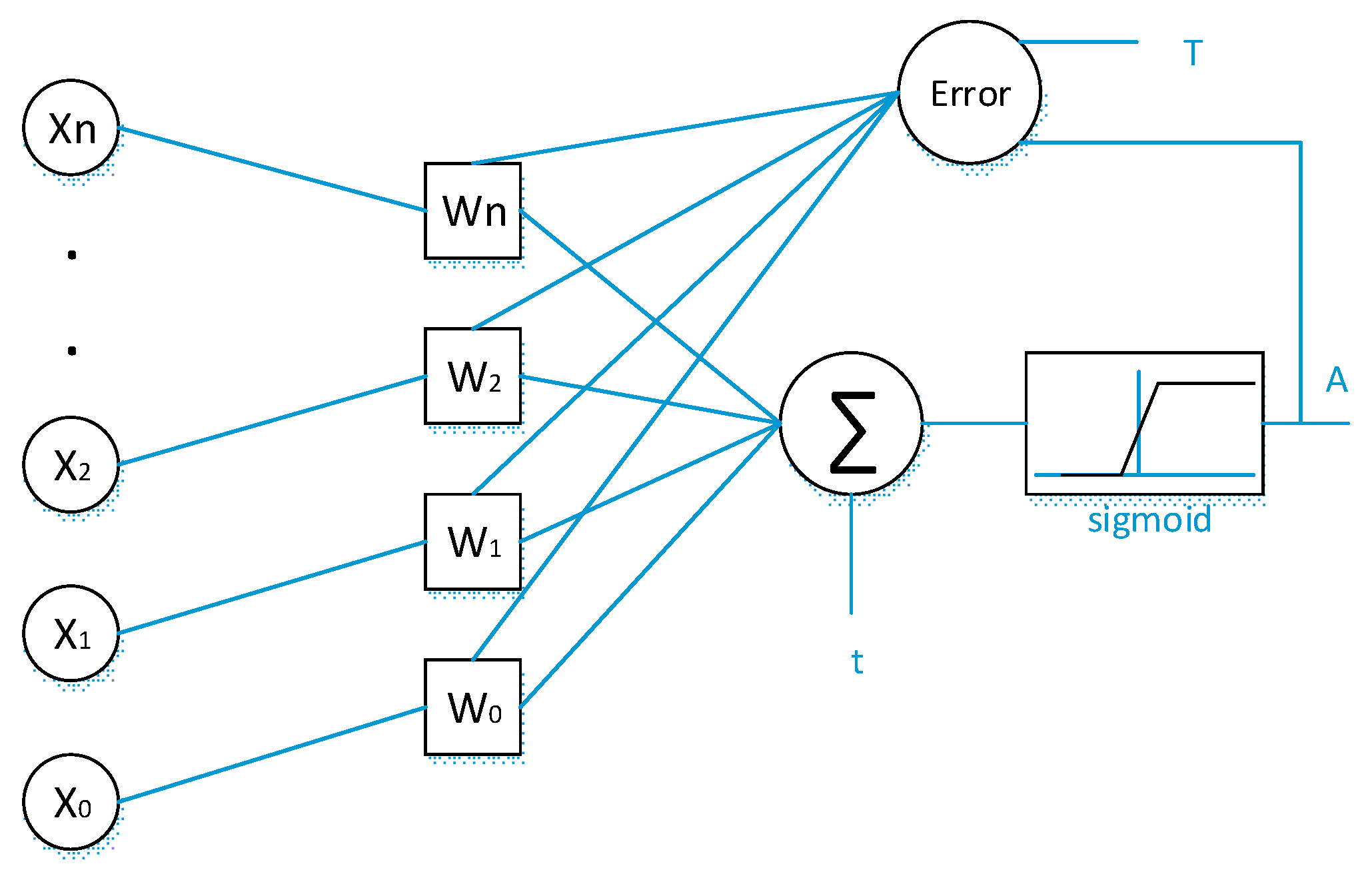
2. Neural Network Approach
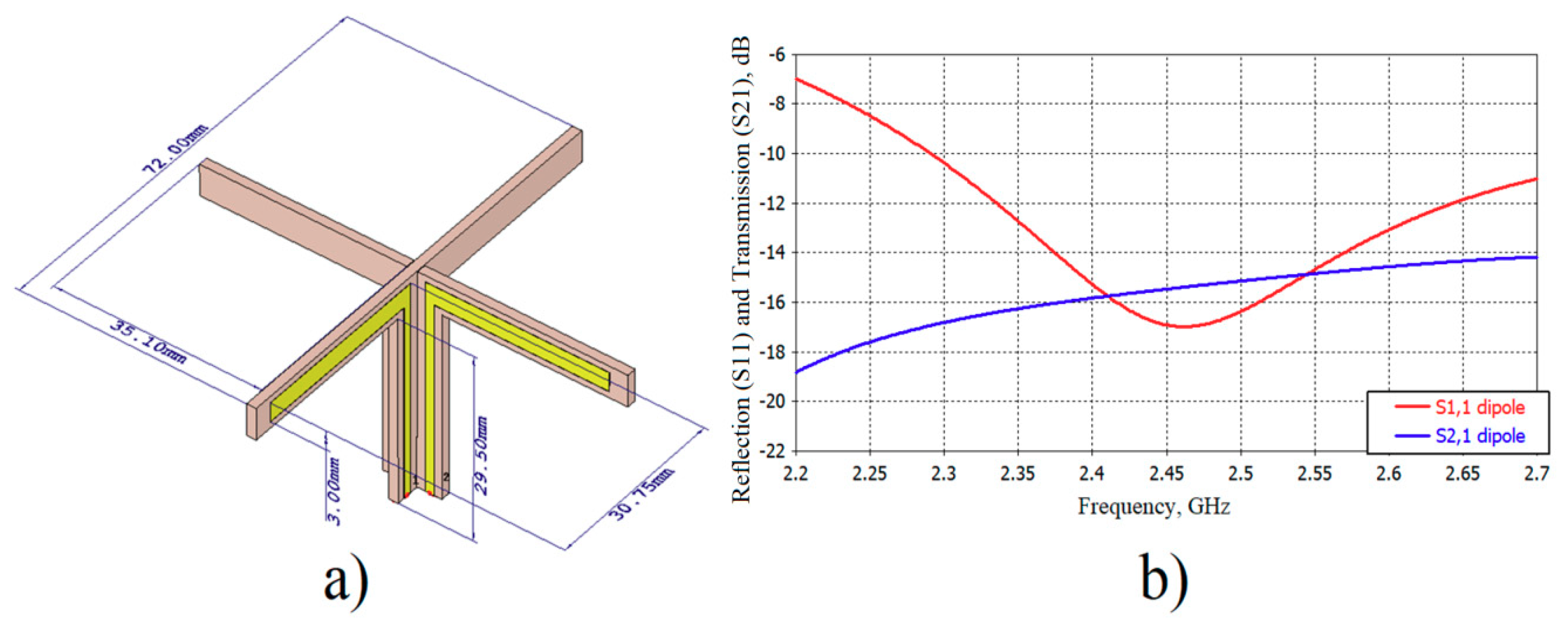
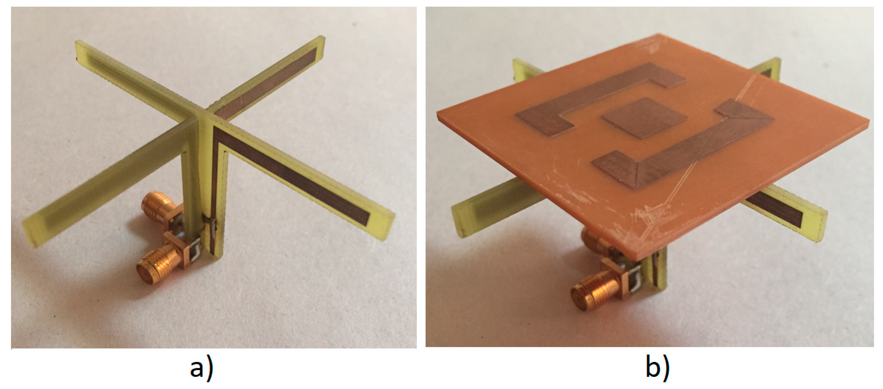
3. Cross-Dipole Antenna Design
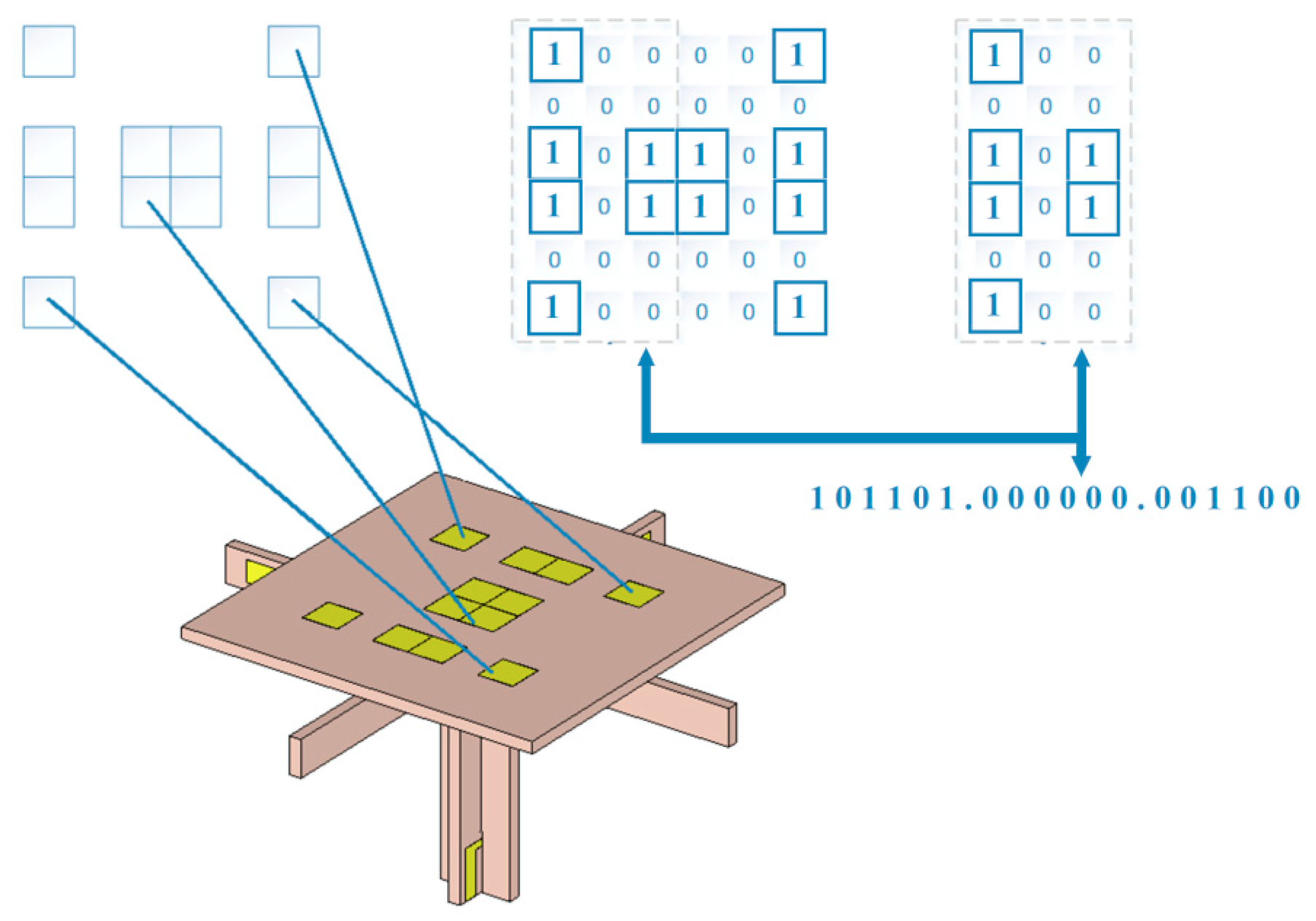
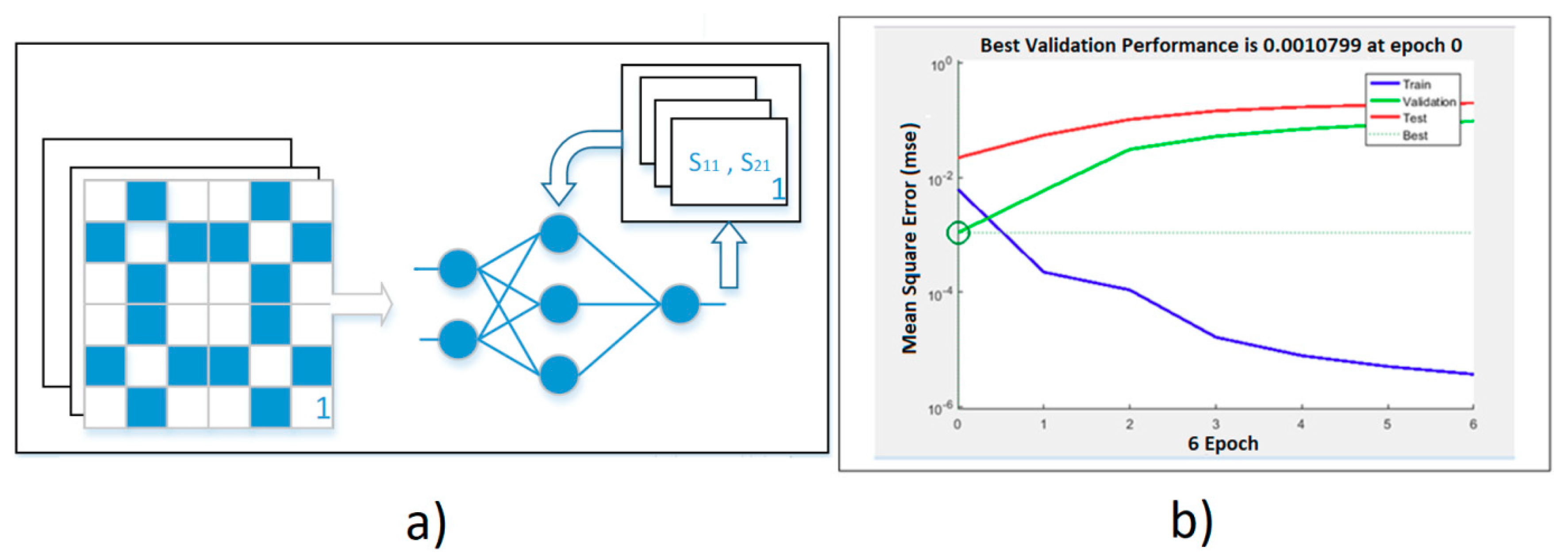
4. Reduction of Mutual Coupling by a Neural Network Approach
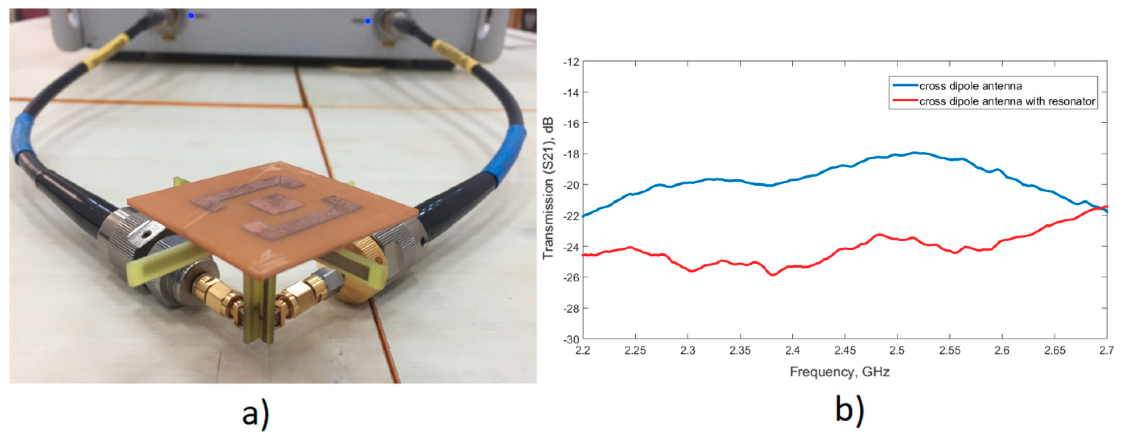
5. Experimental Investigation and Results
6. Conclusions
Author Contributions
Funding
Acknowledgments
Conflicts of Interest
References
- Balanis, C.A. Antenna Theory: Analysis and Design; John Wiley Sons: Hoboken, NJ, USA, 2016. [Google Scholar]
- Zhang, S.; Pedersen, G.F. Mutual coupling reduction for UWB MIMO antennas with a wideband neutralization line. IEEE Antennas Wirel. Propag. Lett. 2015, 15, 166–169. [Google Scholar] [CrossRef]
- Ghosh, T.; Ghosal, S.; Mitra, D.; Bhadra Chaudhuri, S.R. Mutual coupling reduction between closely placed microstrip patch antenna using meander line resonator. Prog. Electromagn. Res. 2016, 59, 115–122. [Google Scholar] [CrossRef]
- Farahani, M.; Pourahmadazar, J.; Akbari, M.; Nedil, M.; Sebak, A.R.; Denidni, T.A. Mutual coupling reduction in millimeter-wave MIMO antenna array using a metamaterial polarization-rotator wall. IEEE Antennas Wirel. Propag. Lett. 2017, 16, 2324–2327. [Google Scholar] [CrossRef]
- Von BM Trindade, D.; Müller, C.; De Castro, M.C.F.; de Castro, F.C. Metamaterials applied to ESPAR antenna for mutual coupling reduction. IEEE Antennas Wirel. Propag. Lett. 2014, 14, 430–433. [Google Scholar] [CrossRef]
- Dadgarpour, A.; Zarghooni, B.; Virdee, B.S.; Denidni, T.A.; Kishk, A.A. Mutual coupling reduction in dielectric resonator antennas using metasurface shield for 60-GHz MIMO systems. IEEE Antennas Wirel. Propag. Lett. 2016, 16, 477–480. [Google Scholar] [CrossRef]
- Li, Q.; Feresidis, A.P.; Mavridou, M.; Hall, P.S. Miniaturized double-layer EBG structures for broadband mutual coupling reduction between UWB monopoles. IEEE Trans. Antennas Propag. 2015, 633, 1168–1171. [Google Scholar] [CrossRef]
- Lee, J.Y.; Kim, S.H.; Jang, J.H. Reduction of mutual coupling in planar multiple antenna by using 1-D EBG and SRR structures. IEEE Trans. Antennas Propag. 2015, 639, 4194–4198. [Google Scholar] [CrossRef]
- Ibrahim, A.A.; Abdalla, M.A.; Abdel-Rahman, A.B.; Hamed, H.F. Compact MIMO antenna with optimized mutual coupling reduction using DGS. Int. J. Microw. Wirel. Technol. 2014, 62, 173–180. [Google Scholar] [CrossRef]
- Bernety, H.M.; Yakovlev, A.B. Reduction of mutual coupling between neighboring strip dipole antennas using confocal elliptical metasurface cloaks. IEEE Trans. Antennas Propag. 2015, 634, 1554–1563. [Google Scholar] [CrossRef]
- Cheng, Y.F.; Ding, X.; Shao, W.; Wang, B.Z. Reduction of mutual coupling between patch antennas using a polarization-conversion isolator. IEEE Antennas Wirel. Propag. Lett. 2016, 16, 1257–1260. [Google Scholar] [CrossRef]
- Jafargholi, A.; Jafargholi, A.; Choi, J.H. Mutual coupling reduction in an array of patch antennas using CLL metamaterial superstrate for MIMO applications. IEEE Trans. Antennas Propag. 2018, 671, 179–189. [Google Scholar] [CrossRef]
- Ghosh, J.; Mitra, D.; Das, S. Mutual coupling reduction of slot antenna array by controlling surface wave propagation. IEEE Trans. Antennas Propag. 2018, 672, 1352–1357. [Google Scholar] [CrossRef]
- Zhang, J.; Li, J.; Chen, J. Mutual coupling reduction of a circularly polarized four-element antenna array using metamaterial absorber for unmanned vehicles. IEEE Access 2019, 7, 57469–57475. [Google Scholar] [CrossRef]
- Ghosh, C.K. A compact 4-channel microstrip MIMO antenna with reduced mutual coupling. AEU-Int. J. Electron. Commun. 2016, 707, 873–879. [Google Scholar] [CrossRef]
- Srivastava, M.; Saini, S.; Thakur, A. Analysis and parameter estimation of microstrip circular patch antennas using artificial neural networks. In Soft Computing: Theories and Applications; Springer: Singapore, 2018; pp. 285–292. [Google Scholar]
- Rajaraman, G.; Sood, K.; Anbazhagan, S. A novel method to compute resonant frequency of metamaterial based patch antennas using neural networks. Int. J. Res. Appl. Sci. Eng. Technol. IJRASET 2016, 41, 321–325. [Google Scholar]
- Nayak, C.; Kumar, P. Optimized design and analysis of microstrip antenna using artificial neural network. In Proceedings of the 2017 International Conference on Current Trends in Computer, Electrical, Electronics and Communication CTCEEC, Karnataka, India, 8–9 September 2017; pp. 114–118. [Google Scholar]
- Xiao, L.Y.; Shao, W.; Jin, F.L.; Wang, B.Z. Multiparameter modeling with ANN for antenna design. IEEE Trans. Antennas Propag. 2018, 667, 3718–3723. [Google Scholar] [CrossRef]
- Altintas, O.; Aksoy, M.; Unal, E.; Akgol, O.; Karaaslan, M. Artificial neural network approach for locomotive maintenance by monitoring dielectric properties of engine lubricant. Measurement 2019, 145, 678–686. [Google Scholar] [CrossRef]


| Variables | Output1 | Output2 | Outpu3 Isolation | |||||||||||||||||
|---|---|---|---|---|---|---|---|---|---|---|---|---|---|---|---|---|---|---|---|---|
| X1 | X2 | X3 | X4 | X5 | X6 | Y1 | Y2 | Y3 | Y4 | Y5 | Y6 | Z1 | Z2 | Z3 | Z4 | Z5 | Z6 | S11 | S22 | S12 |
| 0 | 0 | 0 | 0 | 0 | 0 | 0 | 0 | 0 | 0 | 0 | 0 | 0 | 0 | 0 | 0 | 0 | 0 | −20.64 | −14.82 | −14.98 |
| 0 | 0 | 0 | 0 | 0 | 0 | 0 | 0 | 0 | 0 | 0 | 0 | 0 | 1 | 1 | 0 | 0 | 0 | −30.78 | −10.59 | −15.89 |
| 0 | 0 | 0 | 0 | 0 | 0 | 0 | 0 | 0 | 0 | 0 | 0 | 1 | 1 | 1 | 0 | 0 | 0 | −27.15 | −10.56 | −15.90 |
| 0 | 0 | 0 | 0 | 0 | 0 | 0 | 0 | 0 | 0 | 0 | 0 | 1 | 1 | 1 | 1 | 0 | 0 | −13.73 | −9.77 | −15.43 |
| 0 | 0 | 0 | 0 | 0 | 0 | 0 | 0 | 0 | 0 | 0 | 0 | 1 | 1 | 1 | 1 | 1 | 0 | −7.84 | −9.68 | −15.51 |
| 0 | 0 | 0 | 0 | 0 | 0 | 0 | 0 | 0 | 0 | 0 | 0 | 1 | 1 | 1 | 1 | 1 | 1 | −4.64 | −9.67 | −15.86 |
| 0 | 0 | 0 | 0 | 0 | 0 | 1 | 0 | 0 | 0 | 0 | 0 | 1 | 1 | 1 | 1 | 1 | 1 | −3.26 | −9.12 | −16.11 |
| 0 | 0 | 0 | 0 | 0 | 0 | 1 | 1 | 0 | 0 | 0 | 0 | 1 | 1 | 1 | 1 | 1 | 1 | −3.78 | −8.38 | −16.19 |
| 0 | 0 | 0 | 0 | 0 | 0 | 1 | 1 | 1 | 0 | 0 | 0 | 1 | 1 | 1 | 1 | 1 | 1 | −4.78 | −6.74 | −16.51 |
| 0 | 0 | 0 | 0 | 0 | 0 | 1 | 1 | 1 | 1 | 0 | 0 | 1 | 1 | 1 | 1 | 1 | 1 | −5.58 | −6.09 | −16.61 |
| 0 | 0 | 0 | 0 | 0 | 0 | 1 | 1 | 1 | 1 | 1 | 0 | 1 | 1 | 1 | 1 | 1 | 1 | −5.62 | −5.96 | −16.64 |
| 0 | 0 | 0 | 0 | 0 | 0 | 1 | 1 | 1 | 1 | 1 | 1 | 1 | 1 | 1 | 1 | 1 | 1 | −4.96 | −5.86 | −16.80 |
| 1 | 0 | 0 | 0 | 0 | 0 | 1 | 1 | 1 | 1 | 1 | 1 | 1 | 1 | 1 | 1 | 1 | 1 | −4.01 | −5.23 | −16.81 |
| 1 | 1 | 0 | 0 | 0 | 0 | 1 | 1 | 1 | 1 | 1 | 1 | 1 | 1 | 1 | 1 | 1 | 1 | −4.35 | −4.77 | −16.81 |
| 1 | 1 | 1 | 0 | 0 | 0 | 1 | 1 | 1 | 1 | 1 | 1 | 1 | 1 | 1 | 1 | 1 | 1 | −4.94 | −3.97 | −16.88 |
| 1 | 1 | 1 | 1 | 0 | 0 | 1 | 1 | 1 | 1 | 1 | 1 | 1 | 1 | 1 | 1 | 1 | 1 | −5.35 | −3.60 | −16.85 |
| 1 | 1 | 1 | 1 | 1 | 0 | 1 | 1 | 1 | 1 | 1 | 1 | 1 | 1 | 1 | 1 | 1 | 1 | −5.33 | −3.43 | −16.76 |
| 1 | 1 | 1 | 1 | 1 | 1 | 1 | 1 | 1 | 1 | 1 | 1 | 1 | 1 | 1 | 1 | 1 | 1 | −4.90 | −3.24 | −16.70 |
| 1 | 1 | 1 | 1 | 1 | 1 | 1 | 1 | 1 | 1 | 1 | 1 | 1 | 1 | 0 | 1 | 0 | 1 | −4.77 | −3.22 | −15.94 |
| 1 | 1 | 1 | 1 | 1 | 1 | 1 | 1 | 1 | 0 | 1 | 1 | 1 | 1 | 0 | 1 | 0 | 1 | −4.66 | −3.30 | −15.78 |
| 1 | 0 | 1 | 1 | 1 | 1 | 1 | 1 | 1 | 0 | 1 | 1 | 1 | 1 | 0 | 1 | 0 | 1 | −3.87 | −3.40 | −15.49 |
| 1 | 0 | 0 | 1 | 1 | 1 | 1 | 1 | 1 | 0 | 1 | 1 | 1 | 1 | 0 | 1 | 0 | 1 | −3.14 | −3.75 | −15.21 |
| 1 | 0 | 0 | 0 | 1 | 1 | 1 | 1 | 1 | 0 | 1 | 1 | 1 | 1 | 0 | 1 | 0 | 1 | −1.24 | −4.61 | −15.33 |
| 1 | 0 | 0 | 0 | 0 | 1 | 1 | 1 | 1 | 0 | 1 | 1 | 1 | 1 | 0 | 1 | 0 | 1 | −1.24 | −5.00 | −15.77 |
| 1 | 0 | 0 | 0 | 0 | 1 | 1 | 1 | 0 | 0 | 1 | 1 | 1 | 1 | 0 | 1 | 0 | 1 | −19.42 | −5.94 | −16.23 |
| 1 | 0 | 0 | 0 | 0 | 1 | 1 | 0 | 0 | 0 | 1 | 1 | 1 | 1 | 0 | 1 | 0 | 1 | −20.90 | −6.34 | −16.28 |
| 1 | 0 | 0 | 0 | 0 | 1 | 1 | 0 | 0 | 0 | 1 | 1 | 1 | 1 | 0 | 0 | 0 | 1 | −20.00 | −6.43 | −16.60 |
| 1 | 0 | 0 | 0 | 0 | 1 | 1 | 0 | 0 | 0 | 1 | 1 | 1 | 0 | 0 | 0 | 0 | 1 | −19.83 | −6.53 | −16.67 |
| 1 | 0 | 0 | 0 | 0 | 1 | 1 | 0 | 0 | 0 | 1 | 0 | 1 | 0 | 0 | 0 | 0 | 1 | −20.49 | −4.62 | −16.90 |
| 1 | 0 | 0 | 0 | 0 | 1 | 1 | 0 | 0 | 0 | 1 | 1 | 0 | 0 | 0 | 0 | 0 | 1 | −21.16 | −4.88 | −17.02 |
| 1 | 0 | 0 | 0 | 0 | 1 | 0 | 0 | 0 | 0 | 1 | 1 | 0 | 0 | 0 | 0 | 0 | 1 | −21.57 | −4.90 | −17.06 |
| 0 | 0 | 0 | 0 | 0 | 1 | 0 | 0 | 0 | 0 | 1 | 0 | 0 | 0 | 0 | 0 | 0 | 1 | −21.83 | −4.90 | −17.09 |
| 0 | 0 | 0 | 0 | 0 | 1 | 0 | 0 | 0 | 0 | 0 | 0 | 0 | 0 | 0 | 0 | 0 | 1 | −21.27 | −13.09 | −16.27 |
| 1 | 1 | 1 | 0 | 0 | 1 | 0 | 0 | 0 | 0 | 0 | 0 | 0 | 0 | 0 | 0 | 0 | 1 | −21.28 | −13.11 | −16.13 |
| 1 | 1 | 1 | 1 | 1 | 1 | 0 | 0 | 0 | 0 | 0 | 0 | 0 | 0 | 0 | 0 | 0 | 1 | −11 | −12.82 | −16.34 |
| 1 | 1 | 1 | 1 | 1 | 1 | 0 | 0 | 0 | 0 | 0 | 1 | 0 | 0 | 0 | 0 | 0 | 1 | −5.35 | −16.78 | −16.50 |
| 1 | 1 | 1 | 1 | 1 | 1 | 1 | 0 | 0 | 0 | 0 | 1 | 1 | 0 | 0 | 0 | 0 | 1 | −1.9 | −1.95 | −13.31 |
| 1 | 1 | 1 | 1 | 1 | 1 | 1 | 0 | 0 | 0 | 0 | 1 | 0 | 0 | 0 | 0 | 0 | 0 | −5.47 | −12.17 | −16.46 |
| 1 | 1 | 0 | 0 | 1 | 1 | 1 | 0 | 0 | 0 | 0 | 1 | 0 | 0 | 0 | 0 | 0 | 0 | −19.75 | −12.55 | −16.41 |
| 1 | 1 | 0 | 0 | 1 | 1 | 1 | 0 | 0 | 0 | 0 | 1 | 0 | 0 | 1 | 1 | 0 | 0 | −24.53 | −9.74 | −15.79 |
| 1 | 1 | 0 | 0 | 1 | 1 | 1 | 1 | 0 | 0 | 1 | 1 | 0 | 0 | 1 | 1 | 0 | 0 | −1.57 | −1.22 | −10.45 |
| 0 | 1 | 0 | 0 | 1 | 0 | 1 | 0 | 0 | 0 | 1 | 1 | 0 | 0 | 1 | 1 | 0 | 0 | −25.10 | −9.73 | −15.75 |
| 0 | 1 | 1 | 0 | 1 | 0 | 1 | 0 | 0 | 0 | 1 | 1 | 0 | 0 | 1 | 1 | 0 | 0 | −20.95 | −9.79 | −15.71 |
| 0 | 1 | 1 | 1 | 1 | 0 | 1 | 0 | 0 | 0 | 1 | 1 | 0 | 0 | 1 | 1 | 0 | 0 | −7.63 | −9.73 | −16.26 |
| 0 | 1 | 1 | 1 | 1 | 0 | 1 | 0 | 1 | 0 | 1 | 1 | 0 | 0 | 1 | 1 | 0 | 0 | −7.76 | −7.11 | −15.20 |
| 0 | 1 | 1 | 1 | 1 | 0 | 1 | 0 | 1 | 0 | 1 | 1 | 0 | 0 | 1 | 1 | 0 | 0 | −8.27 | −1.64 | −14.89 |
| 0 | 0 | 1 | 1 | 0 | 0 | 0 | 0 | 0 | 0 | 0 | 0 | 0 | 0 | 1 | 1 | 0 | 0 | −27.53 | −9.88 | −15.59 |
| 1 | 0 | 1 | 1 | 0 | 1 | 0 | 0 | 0 | 0 | 0 | 0 | 0 | 0 | 1 | 1 | 0 | 0 | −27.01 | −9.87 | −15.63 |
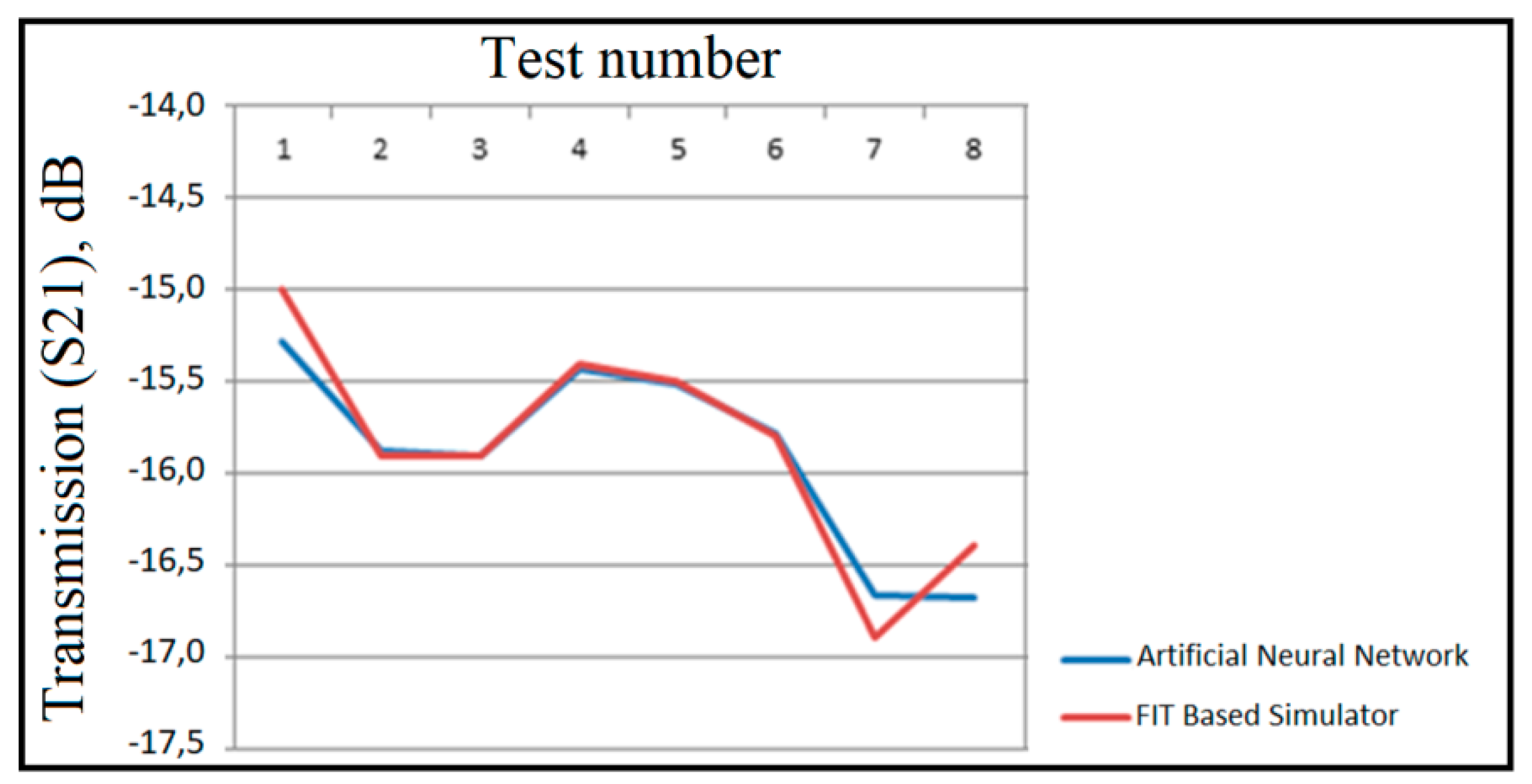
| X1 | X2 | X3 | X4 | X5 | X6 | Y1 | Y2 | Y3 | Y4 | Y5 | Y6 | Z1 | Z2 | Z3 | Z4 | Z5 | Z6 | Artificial Neural Network | FIT Based Simulator | % Error |
|---|---|---|---|---|---|---|---|---|---|---|---|---|---|---|---|---|---|---|---|---|
| 0 | 0 | 0 | 0 | 0 | 0 | 0 | 0 | 0 | 0 | 0 | 0 | 0 | 0 | 0 | 0 | 0 | 0 | −15.2782 | −15 | 1.85 |
| 0 | 0 | 0 | 0 | 0 | 0 | 0 | 0 | 0 | 0 | 0 | 0 | 0 | 1 | 1 | 0 | 0 | 0 | −15.8851 | −15.9 | 0.09 |
| 0 | 0 | 0 | 0 | 0 | 0 | 0 | 0 | 0 | 0 | 0 | 0 | 1 | 1 | 1 | 0 | 0 | 0 | −15.9021 | −15.9 | 0.01 |
| 0 | 0 | 0 | 0 | 0 | 0 | 0 | 0 | 0 | 0 | 0 | 0 | 1 | 1 | 1 | 1 | 0 | 0 | −15.4356 | −15.4 | 0.23 |
| 0 | 0 | 0 | 0 | 0 | 0 | 0 | 0 | 0 | 0 | 0 | 0 | 1 | 1 | 1 | 1 | 1 | 0 | −15.5183 | −15.5 | 0.11 |
| 1 | 1 | 1 | 1 | 1 | 1 | 1 | 1 | 1 | 0 | 1 | 1 | 1 | 1 | 0 | 1 | 0 | 1 | −15.7793 | −15.8 | 0.13 |
| 1 | 0 | 1 | 0 | 1 | 0 | 1 | 0 | 1 | 0 | 1 | 0 | 1 | 0 | 1 | 0 | 1 | 0 | −16.6678 | −16.9 | 1.37 |
| 0 | 1 | 0 | 1 | 0 | 1 | 0 | 1 | 0 | 1 | 0 | 1 | 0 | 1 | 0 | 1 | 0 | 1 | −16.6741 | −16.4 | 1.67 |
© 2020 by the authors. Licensee MDPI, Basel, Switzerland. This article is an open access article distributed under the terms and conditions of the Creative Commons Attribution (CC BY) license (http://creativecommons.org/licenses/by/4.0/).
Share and Cite
Ozdemir, E.; Akgol, O.; Ozkan Alkurt, F.; Karaaslan, M.; Abdulkarim, Y.I.; Deng, L. Mutual Coupling Reduction of Cross-Dipole Antenna for Base Stations by Using a Neural Network Approach. Appl. Sci. 2020, 10, 378. https://doi.org/10.3390/app10010378
Ozdemir E, Akgol O, Ozkan Alkurt F, Karaaslan M, Abdulkarim YI, Deng L. Mutual Coupling Reduction of Cross-Dipole Antenna for Base Stations by Using a Neural Network Approach. Applied Sciences. 2020; 10(1):378. https://doi.org/10.3390/app10010378
Chicago/Turabian StyleOzdemir, Ersin, Oguzhan Akgol, Fatih Ozkan Alkurt, Muharrem Karaaslan, Yadgar I. Abdulkarim, and Lianwen Deng. 2020. "Mutual Coupling Reduction of Cross-Dipole Antenna for Base Stations by Using a Neural Network Approach" Applied Sciences 10, no. 1: 378. https://doi.org/10.3390/app10010378
APA StyleOzdemir, E., Akgol, O., Ozkan Alkurt, F., Karaaslan, M., Abdulkarim, Y. I., & Deng, L. (2020). Mutual Coupling Reduction of Cross-Dipole Antenna for Base Stations by Using a Neural Network Approach. Applied Sciences, 10(1), 378. https://doi.org/10.3390/app10010378