Abstract
Reduction of noise generated by devices is an important problem, both in industrial environments where high sound pressure levels may damage hearing, and in households where the sound pressure level is usually moderate, but may cause discomfort and stress. Classically used passive methods often have poor performance for low frequencies. Alternatively, active control can be used to improve noise reduction in this frequency range. In the proposed approach, noise generated by devices may be reduced by controlling vibrations of the casing. The authors previously confirmed the performance of the proposed active control approach using a dedicated noise-canceling casing. Herein, we describe further development and application of the method to an off-the-shelf washing machine. Electrodynamic actuators were installed on four walls of the washing machine. The performance of the control systems was experimentally evaluated during the real spinning phase and the results are reported here.
1. Introduction
Noise is one of the most common hazards in industrial environments. High sound pressure levels may cause hearing loss, induce stress, reduce comfort and also bring voice communication problems. Thus, noise reduction is an important topic. The best solution is to reduce the noise level at the source. However, existing possibilities have many limitations. Commonly used passive noise reduction systems have poor performance for low frequencies. The barrier must be too thick (and in many cases also too heavy) for practical usage. Such limitations influenced interest in active systems, which may be very effective for low frequencies and complement passive methods in their weak points [1,2,3]. A number of single panel systems were developed [4,5,6], using which, vibrations of a thin plate were controlled by piezoelectric or electrodynamic actuators and the noise emission from the plate was reduced. For control of noise emission in three-dimensional space, multiple flat panels are required. The idea of using such an approach for the whole casing was initially proposed by Fuller et al. [7]. A similar idea was later strongly developed and applied by the authors of [8,9].
For higher reduction levels, walls made of two panels were also investigated [10,11,12]. Such an approach can also be used for the whole casing. However, double-panel walls have some disadvantages: the walls must be thicker; the mass must be higher; and the mass-air-mass resonance might be a potential problem. Moreover, double-panel walls have negative influence on thermal conductivity of the casing.
Less effective alternatives for active control are semi-active control of walls with shunt systems [13] or systems with energy recovery [14,15], which could be potentially used for active control. However, both possibilities are out of the scope of this paper.
Dedicated, additional active noise-reducing casings provide good global noise reduction. However, they increase the dimensions and weight of the device, and they also have an influence on thermal dissipation. Hence, whenever possible, the best way would be to use original device casing. Nonetheless, this approach is much more complex than using a dedicated casing because the device casing was not designed on purpose for active control. The mechanical structure of the original casing is usually sophisticated, often including numerous bends, embossing and internal mountings. Hence, an optimization of actuators and sensors placement is much more difficult. Also, there is a vibrational coupling between the device and its casing. The active control system should, thus, not only provide noise transmission reduction, but also control noise emission from walls excited by vibrations. Taking all these into account, the original device casings are vibroacoustic plants that are very challenging to control.
A simplified problem, where a loudspeaker was placed inside the device’s casing, was already investigated by the authors of [16]. In this paper, real noise generated directly by the enclosed device was reduced during its regular operation. It is a factor that also increases the difficulty of the subject, because the real device is a spatially-distributed noise source that excites the original casing both vibrationally and acoustically.
The approach proposed in this paper has been tested on a regular, off-the-shelf washing machine with its original casing, during spinning, when it generates high sound pressure levels. Experimental results are presented, proving for the first time under real conditions, the concept of the proposed active casing method. Moreover, details about the active control system are also provided, including switched-error modification to the original filtered-x least mean square (FxLMS) algorithm and a distributed control scheme that facilitates implementation on multiple simpler controllers.
2. Active Noise Control
The goal of the proposed active noise control system is to achieve global noise reduction. It is assumed that the most significant noise transmission path is through the casing walls and that the goal can be achieved by controlling device casing vibrations. The device casing vibrations might be induced by noise inside the casing and by mechanical vibrations of elements connected to the casing. The vibrational coupling can be reduced by vibration control systems, usually passive ones. For instance, in the washing machine we used, all moving parts, i.e., the drum and the engine, are partially isolated from the casing by passive vibration isolators. However, even with ideal vibration isolation, the vibrations of isolated subsystems may still propagate through the air. The acoustic path is usually harder to control. Passive sound absorbing materials can be mounted on walls; however, the performance for low frequencies is limited. The active control system of device casing by appropriate control of casing’s vibration should provide good reduction of noise propagated through both paths: sound and mechanical vibrations.
The control of device casing vibrations is achieved by using actuators mounted on the casing. The control of a whole casing for wide frequency band requires a large number of actuators, a lot of output channels and high processing power. For practical implementations, distributed control using multiple simpler controllers is preferred. Thus, the control algorithm is explicitly divided into P tasks [17]. They can operate on multiple processing units (processors, cores) in a single system or even independent systems that share some signals: the reference signal, error signals and signals needed for acoustic feedback elimination, if needed.
Figure 1 shows the simplified block diagram of the Active Noise Control (ANC) system. It is based on the filtered-x least mean square (FxLMS) algorithm architecture. It offers an online adaptation scheme that is necessary for the considered plant due to the non-stationarity of the primary noise (among others, due to varying washing program) and the time-varying plant itself (the primary and secondary paths may change due to, e.g., the heat produced by the operating device). On the other hand, the FxLMS algorithm, among the adaptive control algorithms, offers a satisfactory performance, while requiring affordable computational power, what enables its practical real-time implementation. Nevertheless, a number of important modifications have been proposed and applied to the original FxLMS algorithm to better fit the requirements of the active casing control system.
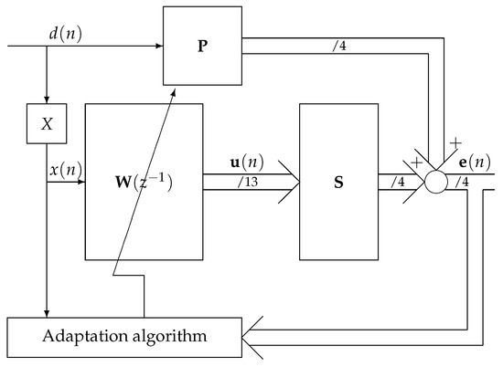
Figure 1.
Simplified ANC system block diagram.
The primary noise propagates though primary paths , and after being measured, by the feed-forward control system: the reference path X; set of control filters , one per actuator; and by secondary paths. The adaptation algorithm adapts control filter weights to achieve destructive interference. The control signals for all actuators are generated by linear adaptive filtration of a single reference signal:
where is a vector of parameters of the adaptive control filter for the cth output of the pth task; the is the number of parameters of each control filter. The is a vector of regressors of the reference signal , the same for all outputs.
Control filter weights are updated using the switched-error normalized leaky FxLMS algorithm with only one active error [18]. This algorithm adapts the weights of the control filter using multiple error signals, such multiple error FxLMS [19]; however, in each sample only one error is used. This reduces the computational complexity of the adaptation algorithm by the number of errors at cost of the convergence rate. Reduced computational complexity allows for implementation of the algorithm on slower hardware or for implementation of more advanced algorithms, such as algorithms with nonlinear control filters or artificial neural networks [20,21], on the same hardware.
Selected error, , is switched in a round-robin fashion at frequency higher than FxLMS algorithm convergence rate, so the FxLMS algorithm averages control filter weights over all errors. is the period of error switching. The selected error is set according to:
where is the number of errors.
Adaptive control filter weights are updated according to the single-error leaky FxLMS with normalization:
where is a constant related to leak; is the normalized LMS step size; is the LMS leak factor; is a binary mask signal, equal to 0 or 1, used to disable adaptation when the vector of regressors of the reference signal are not ready; is the LMS step size for the pth task, is a vector of regressors of the filtered reference; and is the th error signal.
The normalization is, however, done differently than in the single-error algorithm, because the step size must be the same for all error signals; otherwise, the algorithm would use different errors with different weights. The reference signal power is normalized over a longer horizon:
where is an estimate of the total power of all filtered reference signals [18], and is a small positive constant to avoid division by zero. There are many other variable-step LMS algorithms [22], which could be used. The only requirement is that the step size for all errors is about the same.
The filtered reference signals are obtained by filtration of the reference signal by appropriate models of secondary paths:
where is the model of the secondary path from the c-th output of the p-th task to the -th error signal, is the number of parameters of this model and is a vector of regressors of the reference signal.
As the reference signal , the signal from reference microphone can be directly used. However, if vibrations generated by actuators used by the control system have significant influence on the reference microphone signal, then acoustic feedback path may reduce the performance of the system or even cause instability. In such a case it is recommended to reduce the feedback path influence by removing all modeled contributions of outputs to the reference microphone:
where is the number of outputs of the p-th task, is a model of the acoustic feedback path, with parameters, and is a vector of regressors of the c-th output of the p-th task.
3. Experimental Verification
3.1. Plant
The experiments were performed on a washing machine presented in Figure 2. The washing machine casing has different features, such as bends, embossing and internal mountings, which are not present in dedicated noise-cancelling casings. It makes the task of mathematical modelling of casing walls significantly more difficult, but such a model has to be developed in order to find appropriate locations for the actuators (if the actuators would be attached to the casing walls surface without such analysis, e.g., at random locations, it could result in inefficient control or even complete lack of controllability for certain modes of the structure, decreasing the overall performance of the control system). Therefore, a simplified model of the casing based on Mindlin–Reissner plate theory was used. Each wall of the casing was modeled independently and interactions between plates were neglected. As with the study performed for previously used, dedicated, light-weight casing shows, such a simplification can be justified for the purpose of actuators’ arrangement optimization, providing satisfactory results [23]. On the other hand, even in a simpler case, when a rigid frame was assumed, acoustic coupling between plates of the casing makes the model much more complex [24].
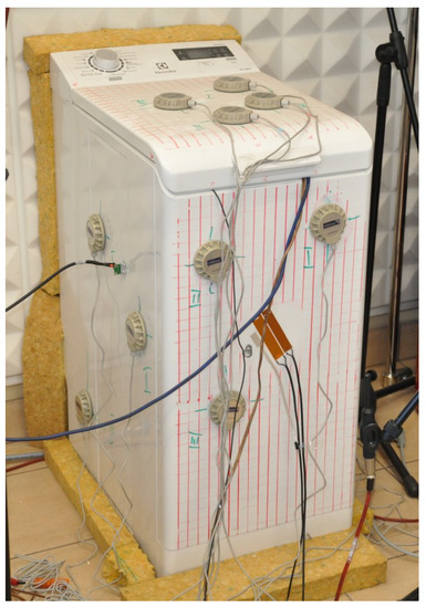
Figure 2.
The washing machine used for experimental verification.
The parameters of the plate models were identified (fitted) by a memetic algorithm. Electrodynamic actuators NXT EX-1 were modeled as additional point masses. The models were solved utilizing the Rayleigh–Ritz assumed mode-shape method. Due to real (and hence imperfect) mountings of each of the casing walls, boundary conditions elastically restrained against both rotation and translation were employed. For a more detailed derivation of the model, the reader is referred to [25].
The resulting model was employed for the process of actuators’ arrangement optimization on the washing machine casing. The adopted aim of the optimization was to maximize the controllability of the least controllable mode in the frequency range up to 300 Hz. Such an objective focuses on avoiding a lack of controllability for modes of the structure in the frequency range considered. The memetic algorithm was used in the optimization process. The optimization variables were the coordinates of actuators on the plate surface. What complicates the process is the fact that the mathematical model has to be recalculated each time a different arrangement of actuators is evaluated (as the actuators’ mass is taken into account in the plate model). Diagonal elements of the controllability Gramian matrix were used in the optimization index J as controllability measures of corresponding modes:
where is the ith diagonal element of the controllability Gramian matrix, corresponding to the ith eigenmode [23]. Depending on the number of eigenmodes included in the given frequency range, a different number of eigenmodes was considered for each wall of the casing. A more detailed description of the optimization process is given in [23].
Thirteen 5 Watt electrodynamic actuators were considered in total to be placed on the casing (four on top wall and three on each other controlled wall). The bottom and back walls were not actively controlled. The arrangement of actuators is presented in Figure 3. As the pair of walls was symmetrical (left and right), a symmetrical configuration was employed for the pair.
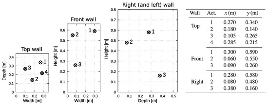
Figure 3.
Arrangement of actuators on the washing machine casing walls. The pair of walls was symmetrical (left and right); hence, only one of them is presented (the front is at depth equal to 0).
The washing machine noise significantly depends on the phase of the washing process. The loudest phase is the final spinning phase. The final spinning speed is configurable, from 400 rpm up to 1200 rpm. In this paper we focus only on final spinning, with spinning speed configured at 1000 rpm or 1200 rpm. Figure 4 shows the spectrogram of the spinning cycle for configured final spinning speed 1200 rpm. The final spinning phase takes about 200 seconds and the noise is clearly louder than in other phases. There are also two stationary phases, which take about 60 seconds, where the drum is spinning at 1000 rpm and the noise is also significant. Thus, the proposed active noise control system was also tested for 1000 rpm and the results are presented.
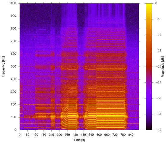
Figure 4.
Spectrogram for 1200 rpm spinning cycle.
The spinning noise signal spectrum contains mostly harmonics of the drum spinning frequency. The observed spinning frequency was actually slightly lower than the nominal frequency. For 1200 rpm, nominally, the highest power spectral density was located around the 6th harmonic, at about 114 Hz, instead of 120 Hz nominally.
3.2. Experimental Setup
Figure 5 shows the laboratory setup used for experiments. The washing machine was placed near a wall, with only four walls exposed. The bottom and back walls were not exposed and not actively controlled. Four error microphones were placed around the casing, each 0.5 m in front of each exposed wall. The reference microphone was placed inside the washing machine.
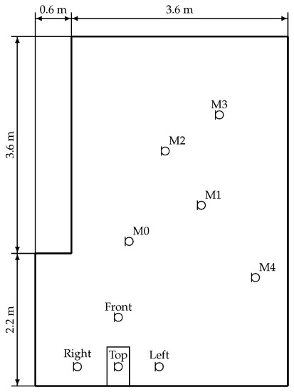
Figure 5.
Laboratory setup.
The noise reduction was measured by five monitoring microphones, M0–M4, not used for control. They were placed at 1.7 m above the floor. The observed noise reduction level at a specific location significantly depends on chosen location due to room acoustics [26]. At some locations, the room acoustics may cause even destructive interference of the primary noise. Hence, the noise level may be significantly underestimated by monitoring microphones placed at certain locations, resulting in underestimated noise reduction level observed after the active noise control is enabled. In that case, even noise increase by properly working active noise control system can be observed at such locations, despite the fact that the actual noise reduction is global in the entire room. The microphones were also non-uniformly placed to limit the spatial aliasing. The area covered by all microphones was larger than wavelength of most significant components of the noise spectrum (90–140 Hz), and the distance between microphones was smaller than half of the wavelength. Thus, the results from microphones should provide a good estimate of noise reduction (at least for the considered frequencies). The noise reduction levels were also verified using sound pressure level meter in other random locations.
3.3. Control System
The control system was implemented using a distributed system with four dSPACE DS1104 boards, each realizing individual task of the control algorithm [17]. All boards have synchronized Analog to Digital Converters (ADCs) and Digital to Analog Converters (DACs) using an external trigger. All cards communicate with each other and the host through a PCI (peripheral component interconnect) bus. The sampling frequency was equal to 2 kHz. To drive the actuators, Monacor STA-850D amplifiers were used, together with the analogue reconstruction filters, custom-made for the dSPACE DS1104 boards employed. Table 1 shows the nominal parameters of the control algorithm. The number of parameters in the secondary path models was selected based on impulse responses of the secondary paths. The number of parameters in the feedback model was selected based on impulse responses of the path to the reference microphone.

Table 1.
Nominal parameters of the control algorithm.
The normalized leaky LMS algorithm step size, , and leak factor, , here selected based on the performance of the control system. The leakage introduced by the parameter enhances robustness of the algorithm [27]. The noise control system performance was measured with reproductible noise generated by a loudspeaker placed inside the drum. A recorded spinning noise at 1200 rpm was used to evaluate the noise reduction.
Figure 6 shows the average sound pressure level (SPL) at error and monitor microphones for a different . The SPLs were measured after 15 min of operation of the control system. The averaging was performed on sound pressure power and then converted to sound pressure level. The optimal range for such adaptation time is around 0.0003 to 0.002.
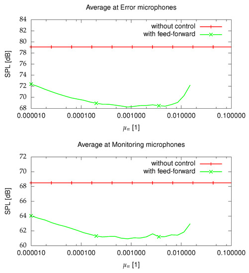
Figure 6.
Average SPL at error and monitor microphones for reproduced spinning noise at 1200 rpm for a different after 15 min, .
Figure 7 shows the average SPLs at error and monitor microphones for a different . The SPLs were measured after 15 min of operation of the control system. The optimal range is around 0.0005 to 0.001. The leakage allows for finding better power distribution for different actuators. Without a leak, the system is under-determined, because the number of actuators is larger than the number of errors. Additionally, for some actuators the control signal limits were reached without leakage. The leak has a higher positive effect on monitoring microphones compared to error microphones.
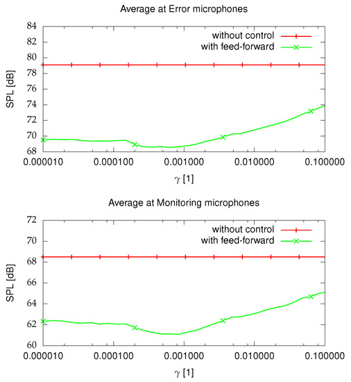
Figure 7.
Average SPL at error and monitor microphones for reproduced spinning noise at 1200 rpm for a different after 15 min, .
3.4. Experimental Results
The performance of the control system was tested for spinning, the loudest phase of washing. Two highest spinning speeds were used, 1000 rpm and 1200 rpm. Table 2 shows the sound pressure levels at different microphones. At all microphone locations a noise reduction was clearly achieved. For 1200 rpm, at monitoring microphones the noise reduction ranged from 2.5 dB at M2, where with control the noise was the quietest, up to 8.4 dB at M0, and without control the noise was the loudest. At 1000 rpm noise levels without control were much lower, and active noise control improvements were also lower; however, still clearly perceptible.
Table 2.
The sound pressure levels at all error and monitoring microphones for a different spinning speed without control and with active noise control enabled (F—front, R—right, L—left, T—top).
The average sound pressure level reduction at monitoring microphones, not used for control, was equal to 5.3 dB for 1200 rpm and 4.0 dB for 1000 rpm. Both results from monitoring microphones and hand-held sound pressure meter confirmed that the noise is reduced globally in the whole room [26].
Figure 8 and Figure 9 show the Power Spectral Densities (PSDs) of signals from microphones and control signals, respectively. Numerous harmonics of drum spinning frequency are clearly visible. The ANC system was able to reduce most important ones, contributing the most to the overall noise generated by the washing machine. The loudest harmonics were observed at frequencies slightly above 100 Hz. It follows also from an analysis of spectrogram presented in Figure 4 that this frequency band is often excited emitting loud noise, probably due to the mechanical structure of the washing machine itself. Given the sweeping nature of the noise generated by the device (due to acceleration and deceleration of the drum) and numerous harmonics, it is very difficult to design a casing that would not represent such resonances; however, by applying the active control system it is possible to mitigate them and significantly reduce the noise emitted to the surrounding environment.
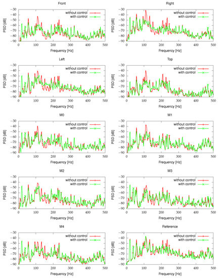
Figure 8.
Power spectral densities of signals from microphones for spinning at 1200 rpm.
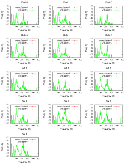
Figure 9.
Power spectral densities of control signals for spinning at 1200 rpm.
4. Conclusions
The idea of noise reduction by active control of device casing walls has been successfully developed and employed for a real washing machine. The only modification to the washing machine was adding actuators and placing a reference microphone inside. The proposed control system was able to reduce the emitted noise globally at monitoring microphones by about 5.3 dB on average, and by 8.3 dB on average at error microphones. Such noise reduction is comparable to the difference in sound pressure level between spinning at the louder 1200 rpm and the quieter 1000 rpm. The average noise reductions for individual frequencies, harmonics of drum rotational frequency, were even higher.
Such noise reduction is clearly perceptible and can make a substantial difference for people exposed to the noise for a prolonged period of time. The authors believe that it can be attractive both for customers who seek quieter devices and for producers to increase their competitiveness.
The washing machine also generates random noise which is harder to reduce for the active control system. Due to the spatially-distributed nature of generation of the random wide-band noise component, more reference sensors could be beneficial to the system, helping to satisfy the causality constraint. Nevertheless, the periodic component of the noise (e.g., due to reciprocal motion in the device) often dominates the noise spectrum for numerous devices in real life. Tonal noise components are also often more disturbing for people, compared to a wide band of random noise. Hence, the authors believe that many applications could largely benefit from the proposed solution, for which the proof of concept has been presented in this paper. The authors hope to encourage other researchers to investigate the concept of active casings for alternative applications and that the details provided concerning the employed active control system will be helpful to them.
Author Contributions
Conceptualization, K.M., S.W. and M.P.; methodology, K.M., S.W. and M.P.; software, K.M.; validation, K.M., S.W. and M.P.; formal analysis, K.M., S.W. and M.P.; investigation, K.M., S.W. and M.P.; resources, K.M., S.W. and M.P.; data curation, K.M. and S.W.; writing—original draft preparation, K.M. and S.W.; writing—review and editing, K.M., S.W. and M.P.; visualization, K.M. and S.W.; supervision, M.P.; funding acquisition, M.P.; project administration, M.P. All authors have read and agreed to the published version of the manuscript.
Funding
The research reported in this paper has been supported by the National Science Centre, Poland, decision number DEC-2017/25/B/ST7/02236, and by State Budget for Science, Poland, in 2019.
Conflicts of Interest
The authors declare no conflict of interest. The funders had no role in the design of the study; in the collection, analyses, or interpretation of data; in the writing of the manuscript, or in the decision to publish the results.
References
- Cheer, J.; Elliott, S.J. Multichannel control systems for the attenuation of interior road noise in vehicles. Mech. Syst. Signal Process. 2015, 60, 753–769. [Google Scholar] [CrossRef]
- Lorente, J.; Ferrer, M.; de Diego, M.; Gonzalez, A. The frequency partitioned block modified filtered-x NLMS with orthogonal correction factors for multichannel Active Noise Control. Digit. Signal Process. 2015, 43, 47–58. [Google Scholar] [CrossRef]
- Lam, B.; Elliott, S.; Cheer, J.; Gan, W.S. Physical limits on the performance of active noise control through open windows. Appl. Acoust. 2018, 137, 9–17. [Google Scholar] [CrossRef]
- Misol, M.; Algermissen, S.; Rose, M.; Monner, H.P. Aircraft Lining Panels with Low-Cost Hardware for Active Noise Reduction. In Proceedings of the 2018 Joint Conference-Acoustics, Ustka, Poland, 11–14 September 2018; pp. 1–6. [Google Scholar]
- Jeong, U.C.; Kim, J.S.; Kim, Y.D.; Oh, J.E. Reduction of radiated exterior noise from the flexible vibrating plate of a rectangular enclosure using multi-channel active control. Appl. Acoust. 2016, 105, 45–54. [Google Scholar] [CrossRef]
- Puri, A.; Modak, S.V.; Gupta, K. Global active control of harmonic noise in a vibro-acoustic cavity using Modal FxLMS algorithm. Appl. Acoust. 2019, 150, 147–161. [Google Scholar] [CrossRef]
- Fuller, C.; Mcloughlin, M.; Hildebrand, S. Active Acoustic Transmission Loss Box. WO Patent No. WO1994009484A1, 1994. [Google Scholar]
- Mazur, K.; Pawelczyk, M. Active control of noise emitted from a device casing. In Proceedings of the 22nd International Congress of Sound and Vibration, Florence, Italy, 12–16 July 2015. [Google Scholar]
- Mazur, K.; Pawelczyk, M. Internal Model Control for a light-weight active noise-reducing casing. Arch. Acoust. 2016, 41, 315–322. [Google Scholar] [CrossRef]
- Mao, Q.; Pietrzko, S.J. Control of sound transmission though double wall partitions using optimally tuned Helmholtz resonators. Acta Acust. United Acust. 2005, 95, 723–731. [Google Scholar]
- Morzyński, L.; Szczepański, G. Double Panel Structure for Active Control of Noise Transmission. Arch. Acoust. 2018, 43, 689–696. [Google Scholar]
- Ho, J.H.; Berkhoff, A. Comparison of various decentralised structural and cavity feedback control strategies for transmitted noise reduction through a double panel structure. J. Sound Vib. 2014, 333, 1857–1873. [Google Scholar] [CrossRef]
- Pietrzko, S.J. Contributions to Noise and Vibration Control Technology; AGH—University of Science and Technology Press: Krakow, Poland, 2009. [Google Scholar]
- Kowal, J.; Kot, A. Active vibration reduction system with energy regeneration. Arch. Control. Sci. 2007, 17, 343–352. [Google Scholar]
- Kowal, J.; Pluta, J.; Konieczny, J.; Kot, A. Energy recovering in active vibration isolation system—Results of experimental research. J. Vib. Control. 2008, 14, 1075–1088. [Google Scholar] [CrossRef]
- Mazur, K.; Wrona, S.; Pawelczyk, M. Active noise control for a washing machine. Appl. Acoust. 2019, 146, 89–95. [Google Scholar] [CrossRef]
- Mazur, K.; Wrona, S.; Pawelczyk, M. Design and implementation of multichannel global active structural acoustic control for a device casing. Mech. Syst. Signal Process. 2018, 98, 877–889. [Google Scholar] [CrossRef]
- Mazur, K.; Pawelczyk, M. Virtual microphone control for a light-weight active noise-reducing casing. In Proceedings of the 23nd International Congress of Sound and Vibration, Athens, Greece, 10–14 July 2016. [Google Scholar]
- Elliott, S.E.; Stothers, I.M.; Nelson, P.A. A Multiple Error LMS Algorithm and Its Application to the Active Control of Sound and Vibration. IEEE Trans. Acoust. Speech Signal Process. 1987, ASSP-35, 1423–1434. [Google Scholar] [CrossRef]
- Snyder, S.D.; Tanaka, N. Active control of vibration using a neural network. IEEE Trans. Neural Netw. 1995, 6, 819–828. [Google Scholar] [CrossRef]
- Cupial, P.; Lacny, L. Neural Network control design considerations for the active damping of a smart beam. J. Theor. Appl. Mech. 2015, 53, 767–774. [Google Scholar] [CrossRef][Green Version]
- Bismor, D.; Czyz, K.; Ogonowski, Z. Review and Comparison of Variable Step-Size LMS Algorithms. Int. J. Acoust. Vib. 2016, 21, 24–39. [Google Scholar] [CrossRef]
- Wrona, S.; Pawelczyk, M. Optimal placement of actuators for Active Structural Acoustic Control of a light-weight device casing. In Proceedings of the 23nd International Congress of Sound and Vibration, Athens, Greece, 10–14 July 2016. [Google Scholar]
- Wyrwał, J.; Zawiski, R.; Pawelczyk, M.; Klamka, J. Modelling of coupled vibro-acoustic interactions in an active casing for the purpose of control. Appl. Math. Model. 2017, 50, 219–236. [Google Scholar] [CrossRef]
- Wrona, S.; Pawelczyk, M. Shaping frequency response of a vibrating plate for passive and active control applications by simultaneous optimization of arrangement of additional masses and ribs. Part I: Modeling. Mech. Syst. Signal Process. 2016, 70–71, 682–698. [Google Scholar] [CrossRef]
- Wiora, J.; Wrona, S.; Pawelczyk, M. Evaluation of measurement value and uncertainty of sound pressure level difference obtained by active device noise reduction. Measurement 2017, 96, 67–75. [Google Scholar] [CrossRef]
- Bismor, D. Extension of LMS stability condition over a wide set of signals. Int. J. Adapt. Control. Signal Process. 2015, 29, 653–670. [Google Scholar] [CrossRef]


© 2020 by the authors. Licensee MDPI, Basel, Switzerland. This article is an open access article distributed under the terms and conditions of the Creative Commons Attribution (CC BY) license (http://creativecommons.org/licenses/by/4.0/).