Article

Numerical Study of the Comparison of Symmetrical and Asymmetrical Eddy-Generation Scheme on the Fire Whirl Formulation and Evolution

1
School of Mechanical and Manufacturing Engineering, University of New South Wales, Sydney, NSW 2052, Australia
2
School of Mechanical and Automotive Engineering, RMIT University, Melbourne, VIC 3000, Australia
3
Australian Nuclear Science and Technology Organisation (ANSTO), Locked Bag 2001, Kirrawee DC, NSW 2232, Australia
*
Author to whom correspondence should be addressed.
Appl. Sci. 2020, 10(1), 318; https://doi.org/10.3390/app10010318
Submission received: 30 November 2019 / Revised: 26 December 2019 / Accepted: 28 December 2019 / Published: 1 January 2020
(This article belongs to the Special Issue Progress in Combustion Diagnostics, Science and Technology)

Abstract

:
A numerical study of the fire whirl formation under symmetrical and asymmetrical entraining configuration is presented. This work aims to assess the effect of eddy-generation configuration on the evolution of the intriguing phenomenon coupled with both flow dynamics and combustion. The numerical framework implements large-eddy simulation, detailed chemistry to capture the sophisticated turbulence-chemistry interaction under reasonable computational cost. It also adopts liquid-based clean fuel with fixed injection rate and uniformed discretisation scheme to eliminate potential interference introduced by various aspects of uncertainties. The result reveals that the nascent fire whirl formulates significantly rapidly under the symmetrical two-slit configuration, with extended flame height and constrained vortex structure, compared with the asymmetrical baseline. However, its revolution orbit gradually diverges from domain centreline and eventually stabilises with a large radius of rotation, whereas the revolution pattern of that from the baseline case is relatively unchanged from the inception of nascent fire whirl. Through the analysis, the observed difference in evaluation pathway could be explained using the concept of circular motion with constant centripetal force. This methodology showcases its feasibility to reveal and visualise the fundamental insight and facilitate profound understanding of the flaming behaviour to benefit both research and industrial sectors.

1. Introduction

Fire whirl is a unique combustion behaviour with a twisting flame structure which significantly intensifies combustion and fluid mechanics, that is often observed in urban and wildland fire scenarios [1]. The swirling reacting flow limits the dispersion rate of the radial flame and stretches the hot plume to progress up to an elevated vertical angular path. Compared with a free-standing diffusion flame, the formulation of the fire whirl often results in a significant increase in rate of combustion, visible flame height, peak flame temperature and the intensity of radiation emitted from flames towards the surrounding Ref [2]. Owing to the unique features associated with this very combustion behaviour, the inception of the fire whirl in a fire scenario could lead to catastrophic effects. In particular, the intensification of heat energy contained within the stretched flame plume and the enhancement in radiation heat transfer to the neighbouring points resulted from a fire whirl could significantly promote the fire spreading towards the surroundings in an accelerated rate. The spatial movement of the swirling plume may also aid the mixing of the reacting gas mixture with the oxidiser to increase the rate of combustion and impose more spatial uncertainties [3]. The presence of the fire whirl has been reported in many notorious fire incidents and been identified as the root causes to aggravate the fire scenario to an unmanageable and untenable manner [4,5]. The formation and evolution of fire whirl, therefore, is a topic of great interest by both industrial communities and industrial sectors.
Previous investigations have identified the three essential criteria that are essential for the formation of this particular swirling flame, namely a thermally driven fluid sink, a radial boundary layer created by a surface drag force, and an eddy-generation source [6,7,8]. In a typical buoyant diffusion flame, the flame structure is acting as the fluid sink which generates hot plumes that naturally drives horizontal flow radically towards the vortex column, which fulfil the first two requirements [9,10]. The eddy-generation mechanism, as the only remaining criteria, therefore, is the most critical element in the transition from free-standing flame towards fire whirl.
The generation of an eddy could naturally occur in a wildland fire scenario that is triggered by topological obstacles, leeward slope, unpredicted weather conditions, etc. [11,12,13]. Such an eddy-generation source could also be observed in compartment fire situation [14,15,16], particularly with the current trend of urban development and the need to construct high-rise building with complex geometry and interior design. A typical example of source of eddy-generation that may trigger the formation of fire whirl in a high-rise building could be an enclosed structure with openings for flow entrainment that induces the circulation, which includes atrium, lift pit, spiral staircase, etc. Those features have been widely implanted as common features in modern building design, such as the Macquarie’s global headquarters dispatched in Figure 1 [17]. Such building geometrical configuration could potentially act as to induce the eddy generation and hence pose a risk to trigger the formulation of fire whirl in a fire incident. For instance, despite the recently developed bio-based flame-retardant materials that effectively restrain the fire from spreading [18,19,20,21,22], the occurrence of the swirling flame has been observed in some recent high profile skyscraper fire incidents including the Beijing Television Cultural Center, Plasco Building, Grenfell Tower, etc. [23]. Understanding the formation of fire whirl and flaming behaviour in an enclosed configuration that resembles the high-rise buildings, is of great benefits to ensure the safety of the resident and occupant as well as to prevent property lost [24,25,26], and therefore is identified as the topic of this study.
Fire whirl has been systematically investigated using experimental means during the past decades to characterise the flame structure and gain the understanding of the transformation of fire whirl from buoyancy-driven free-standing diffusion [7,27,28,29,30,31,32,33]. However, there are some inevitable limitations associated with the experimental method. For instance, the parameters that could be quantified by an experimental approach are limited to temperature, velocity and exhaust gas concentration, which may not be sufficient to reveal the fundamental physical-chemical behaviour and probe the root causes of the observed flaming behaviour. In addition, if the intrusive measuring technique is implemented, e.g., thermocouple for temperature and bidirectional venturi tube for velocity, the experimental data obtained from the literature are often limited to a few points of interest, due to the constraint of the set locations of the measuring device and its associated spatial resolution. Nevertheless, as mentioned previously, the fire whirl is swirling in an unpredictable manner and the flaming structure may not reside in a fixed position. Furthermore, the existence of the measuring devices could inevitably be perturbative, hence potentially alter the very flow dynamics and combustion behaviour [34]. On the other hand, the optical-based diagnostic technique improves the data collection to planar scale without disturbing the measured conditions. It is, however, widely agreed that the optical properties that are critical for the reliability and accuracy of the optical-based measuring result, is often challenging to acquire [35]. The numerical approach hence can serve as a great aid to provide a completed set of data that is often difficult to assess by experimental means alone. The comprehensive data set generated by numerical simulation could work concurrently with experimental measurement to shed light on the fundamental understanding of this topic of interest.
Through the literature review, it has been revealed that the sophisticated flaming behaviour of the fire whirl is governed by the entangled coupling between flow dynamics and combustion kinetics, which could be inevitably affected by various aspects, such as the temperature, buoyancy, vortex, the combustion reaction, etc. which are interrelated and interact during the formulation and evolution of the fire whirl. Such intriguing interaction makes the understanding of the not-well-understood fundamental of the swirling reaction flow more unfathomable. For example, the inception of fire whirl within the enclosure intensifies the combustion process and subsequently varies the energy transfer from the flame structure to the surroundings [36,37,38,39]. If a pool fire configuration is used, the burning rate, which depends on the rate of the liquid fuel, convert into combustible gas mixture via evaporation will be inevitably altered, compared with non-swirled flame counterpart. As a result, ensuring combustion behaviour and heat release rate could also be affected. Similarly, the residence of the swirling reacting flow promotes circulation within the enclosure and enhances the mixing of the reactant with oxidiser and result in a more completed combustion event. The soot formation mainly due to the incomplete combustion within such flame should theoretically be hinder [40,41,42,43]. Nevertheless, the aggravation of the combustion due to the enhance in mixing increase the flame temperature to that often excesses the threshold for soot nucleation, therefore facilitate the inception of in-flame generated soot species [44,45]. The arguably intensified or suppressed generation of soot species is directly correlated to the radiative heat transfer and varies the ensuing combustion process. In addition to the intricate physical and chemical coupling involved, the uncertainties introduced via the numerical modelling could also make the assessment of the fire whirl more cumbersome. For example, the region where combustion occurs is expected to be unfixed, as the hot plume is spinning with the formation of fire whirl as well as with the associated fire tilting, stretching, converging, etc. If the numerical domain is discretised in a non-uniformed manner, the variation in the spatial resolution of each discretised volume may significantly vary the prediction of the parameter of interest, particularly for the evaluation of the sensitive flame temperature [46].
The abovementioned complex coupling and interaction between various aspects have nevertheless not been carefully taken into consideration or restrained in may of the previous studies. It is often noted that heavy sooty flame, pool-based configuration and unevenly distributed mesh strategy that applies finer mesh at near fuel pan regions and coarse mesh at the fringes, has often been implemented in the studies found in the literature. Such implementation makes the quantitative analysis of the fire whirl behaviour unattainable. It is therefore needed to formulate a numerical framework that considers and constraints the preceding coupling processes, and enables the establishment of the correlation between observed changes in flaming behaviour and the proposed parameter of interest.
It also needs to highlight that, the nature of the fire whirl evolution is highly irregular. A fire whirl with typical vortex shape spinning structure could be observed located right above the fuel source at one instant of time, and it could be transformed back to a randomly flickering flame at the next monitoring time instant. The fire whirl rotation pattern and evolution pathway are also highly unpredictable. Such an unpredictable nature of the evolvement and randomly spatial movement of the fire structure and plume poses significant difficulties in fire control, fire prevention, and evacuation planning, if the fire whirl occurs in a high rise building. The studies on fire whirl conducted in the past decades, however, is mainly focused on the characterisation and quantification of the formulated fire whirl from flow dynamic and combustion perspective, upon its formation, or at one very particular time instant that is ideal for the analysis. The qualitative investigation of the evolution of the fire whirl with a detailed description of its various stages, including the ignition, buoyant fire development, formulation of the nascent fire whirl, and the ensuing developments and evolution, has not been thoroughly investigated.
In light of the abovementioned gap in knowledge. This paper will present the first time, using advanced numerical approaches to describe the evolution pathway of two fire whirls formulated under different entrainment configurations from 0.00 s to 50.00 s. This numerical investigation is conducted in a fully controlled numerical environment that isolates all possible variation introduced by intriguing flow dynamic and combustion coupling as well as by variance in numerical modelling aspects, and focuses to establishing the comparison of two fire whirl scenario solely attributed to the different eddy-generation scheme. The enhanced understanding of the evolution pathway of the fire whirl may largely benefit in various aspects including architecture design, fire evacuation planning, as well as fire prevention [47] and extinguishing planning.

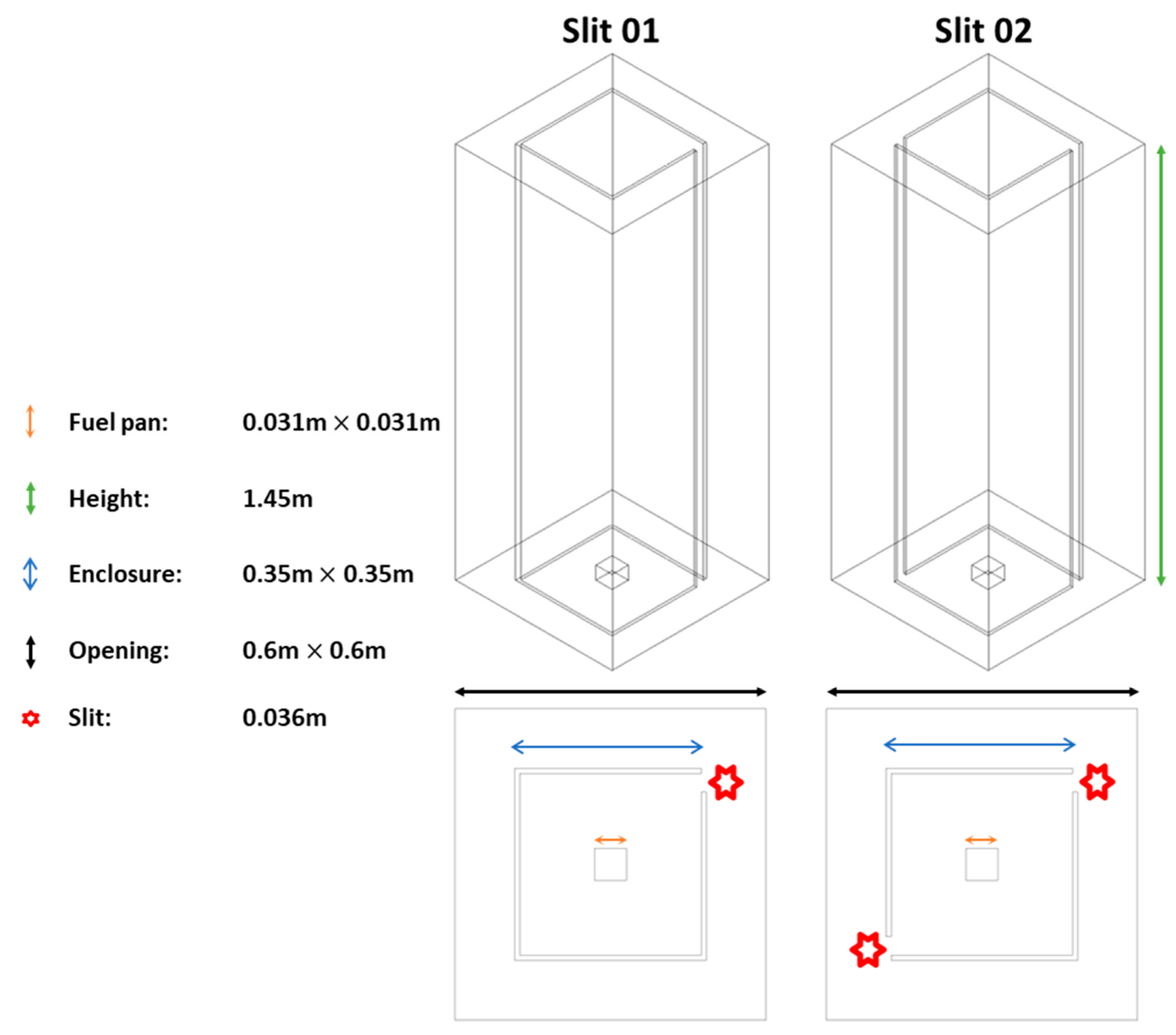
2. Numerical Details

A numerical domain of the baseline model replicating the test rig of one previous experimental study of the fire whirl [48], as well as that with an additional flow channelling slit, was constructed accordingly. The geometric features of the two domains are shown in Figure 2. The detailed description of the numerical configuration of the model has been detailed in our previous work of the characterisation of the fire whirl formulated in an enclosed chamber with different entrainment schemes [49], for the sake of brevity, such information would not be repeated herein. In summary, the geometrical features of the model include a fuel pan located in the domain centreline. The fuel pan is converted from circular to square configuration with the same cross-section area to match the experimental setup to achieve a fully structured mesh, as it significantly enhances the numerical accuracy and computational efficiency.
The domain is discretised to about 800,000 elements using a uniform division algorithm, to eliminate the numerical uncertainty associated with the spatial resolution of the discretised control volume. A doubling of the number of elements to 1,600,000 resulted in only a 5 % difference in the centreline temperature, thus achieving a mesh-independent solution.
The fluid flow and heat transfer within the compartment is described through the conservation equations of continuity, Navier–Stokes, and scalar quantities. A general form of transport equation can be expressed as:
t ( ρ ¯ Φ ) + x i ( ρ ¯ Φ U ˜ i ) = ( Γ Φ ) 2 ρ ¯ Φ x i x i + S ( Φ ) ˜
where Φ is the general field variable dependent on space and time, ρ ¯ is the mean density, U ˜ i is the fluid velocity, Γ Φ is the diffusion term, and S ( Φ ) ˜ is the source term of the general variable. According to the general formula, the transport equations are tabulated in Table 1 as:
Large eddy simulation (LES) and the wall-adapting local eddy-viscosity (WALE) function, is adopted as the turbulence model to describe the turbulent reaction flow behaviour. This turbulence model has been extensively validated and proved to be a valid approach for resolving various wall-bounded turbulence flow applications with a reasonable computational course [8,43,50,51,52,53,54].
The chemical reaction source term in the transport equations of the involved reacting scalars is determined by strained laminar flamelet approach, in which the chemistry is a pre-assumed probability density function (pre-PDF) of two quantities including mixture fraction ( f ) and the scalar dissipation ( χ ). In essence, the mixture fraction governs the amount of the fuel mixture in each control volume element in the simulation domain. The scalar dissipation is a term introduced to describe the strain and extinction of the flame, in which the larger this quantity depicts its departure from its chemical equilibrium [55]. It should be noted that, in the present work, the GRI-MECH 3.0 detailed chemical reaction mechanisms, with includes 325 reaction steps and 53 chemical species [56], was implemented to formulate the flamelet library for the strained laminar flamelet model, with ethylene ( C 2 H 4 ) selected as parental fuel. The presented approach of the modelling turbulence–chemistry interaction has been validated in previous studies to provide a reasonable result with moderate computational burden [50,56,57]. This approach has been validated in previous numerical studies for modelling turbulence chemistry interaction, and has been proved to provide a reasonable result with moderate computational consumption [50,57,58]. It should be highlighted that alcohol-based fuel methanol ( CH 3 OH ), is deliberately selected as the parent fuel to constrain the coupling between radiative energy feedback and the combustion process, due to its feature of clean and soot-free burning behaviour [45]. For the same reason, the concentration of the key building structure unit of soot formation, acetylene ( C 2 H 2 ), in the gas mixture produced by this very parent fuel, is proved to be negligible. The most commonly adopted soot models formulated on C 2 H 2 precursor-based inception and surface growth mechanism are not applicable in this study [59,60,61,62]. As a result, a primitive and computational lightweight two-step soot model is integrated, for concept verification purpose only.
With respect to the boundary conditions, a set flow rate of 0.0216   ms 1 in the direction normal to the fuel surface is applied on the fuel pan. The applied injection velocity is determined on the basis of the cross-sectional area of the fire pan, the density of the parent fuel at a reference temperature, and the heat of combustion of the parent fuel in order to match the targeted heat release rate reported in the experimental study. The constant injection rate ensures an evenly distributed burning profile, regardless of the intensity of flow circulation and energy feedback. The fuel surface is set at an elevated height according to the experimental setup. The top and the periphery of the domain is set as the opening to allow naturally convected air entrainment in and out of the system. The base of the domain is set as a non-slip adiabatic wall, across which no heat or matter is allowed to pass. The simulation is initiated with standard temperature and pressure replicating the ambient conditions for the combustion process to proceed. For convenience, the case with one side entrainment slit is referred to as the Slit 01 case, case 1 , or the baseline case/model, and that with two side entrainment slits is referred as the Slit 02 case, case 2 , or the comparison case/model, in the following sections.
It should be noted that the simulation result is validated against experimental data and achieve good comparison in temperature profile as well as the incoming velocity at the entraining slits at various HABs (height above burners), which is explained in detail in the co-published work [49]. For the sake of brevity, the validation process is not presented in this work.

3. Results

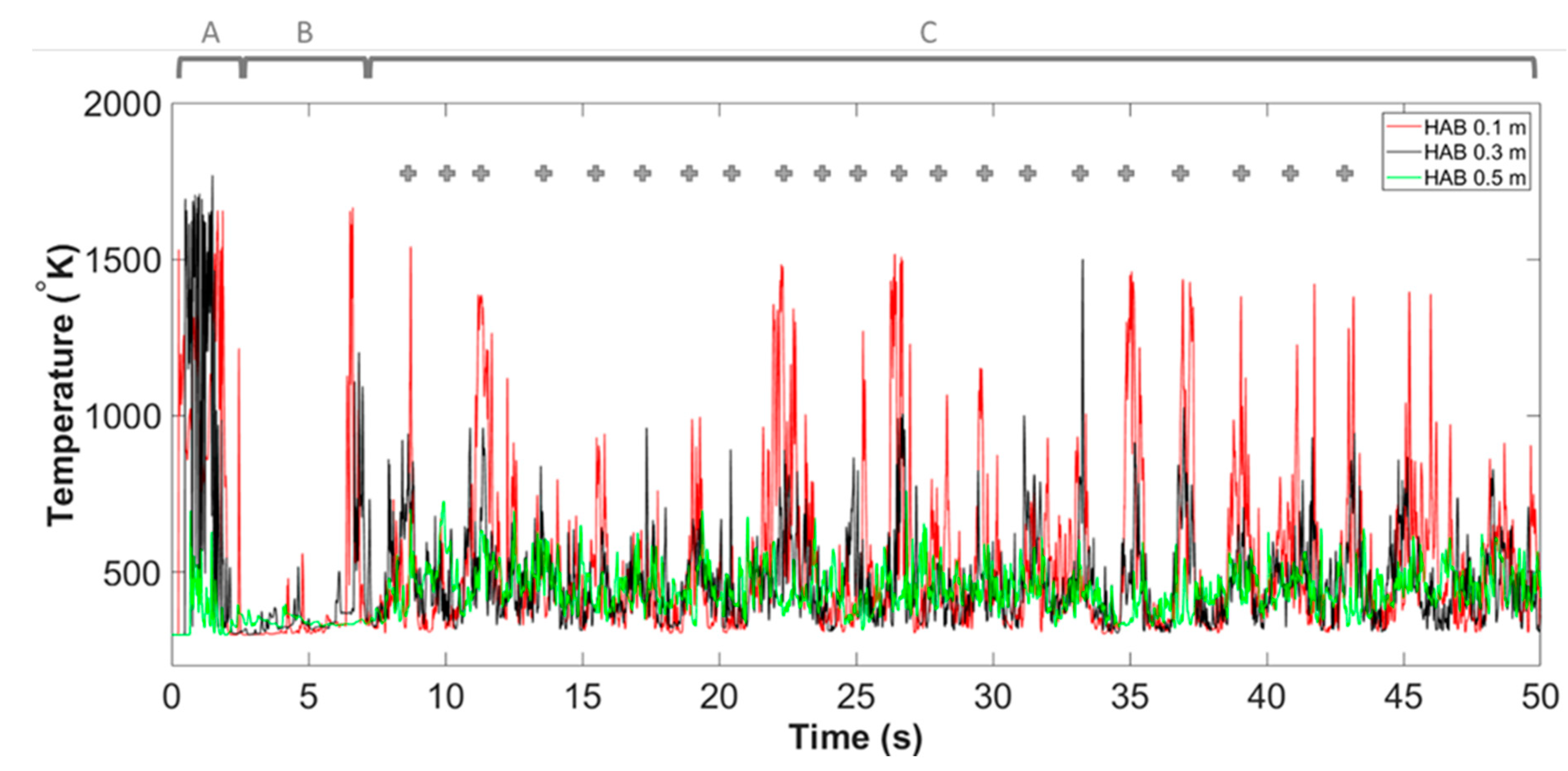
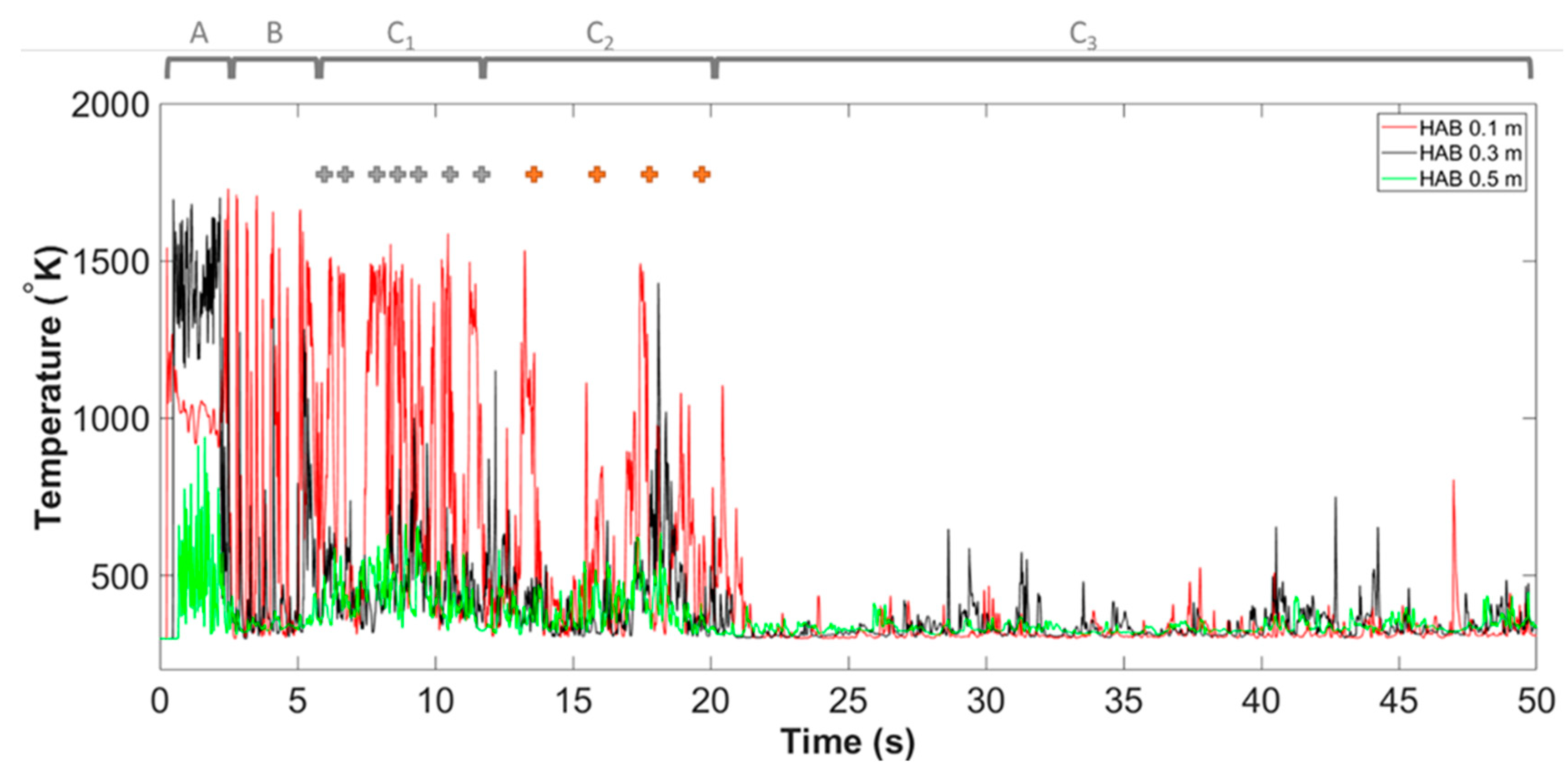
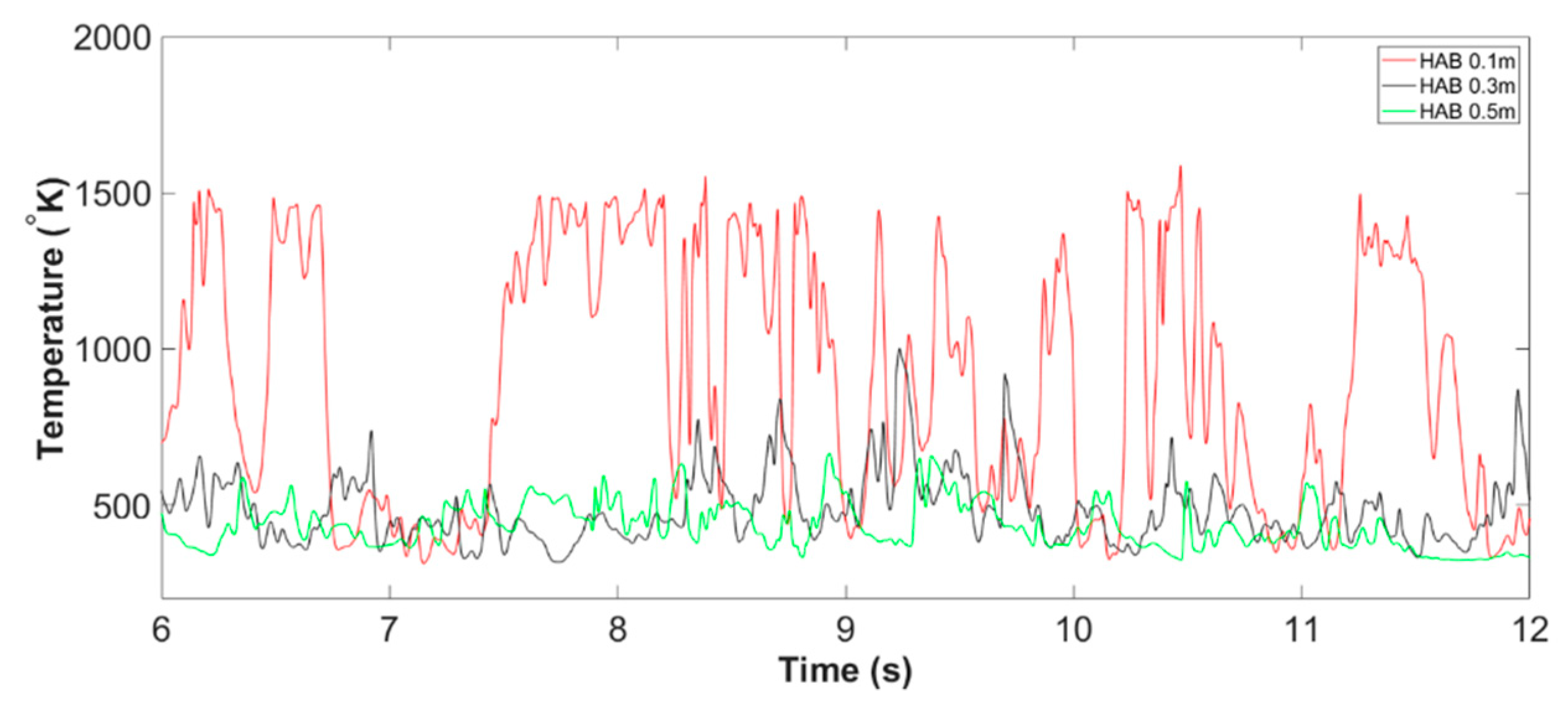
3.1. The Formation and Evolution of Fire Whirl

The flame temperature profile at the domain centreline of all monitoring HABs, from the start of the simulation to 50.00   s for both Slit 01 case and Slit 02 case, are presented in Figure 3 and Figure 4. In general, the evolution of this very flaming phenomenon, based on its combustion behaviours, can be categorised into three main stages. Those include Stage A: flame development; Stage B: fire whirl development and formation; Stage C: fire whirl evolution (the cross symbol indicates the particular time instant the core of the fire whirl is centre in the domain centerline). The characterisation of the formation pathway and evolution of the fire whirl is discussed in detail in the following sections.

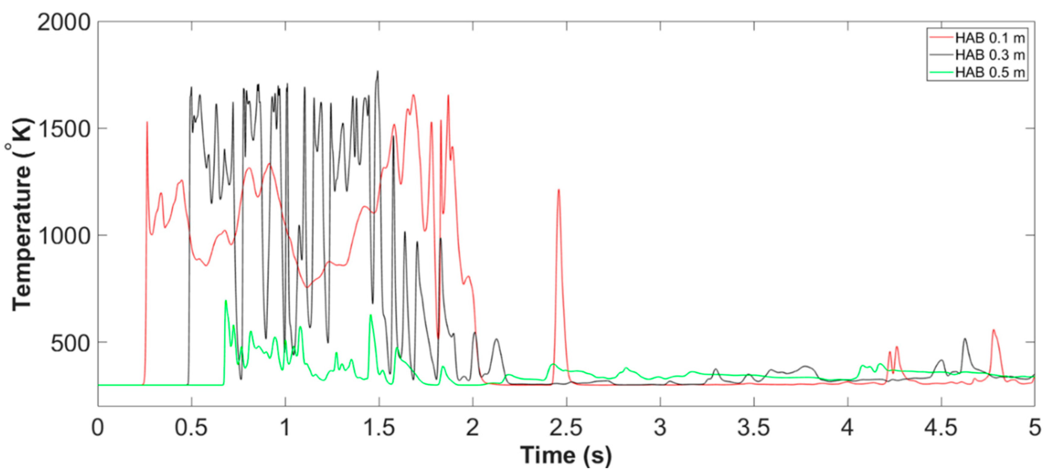
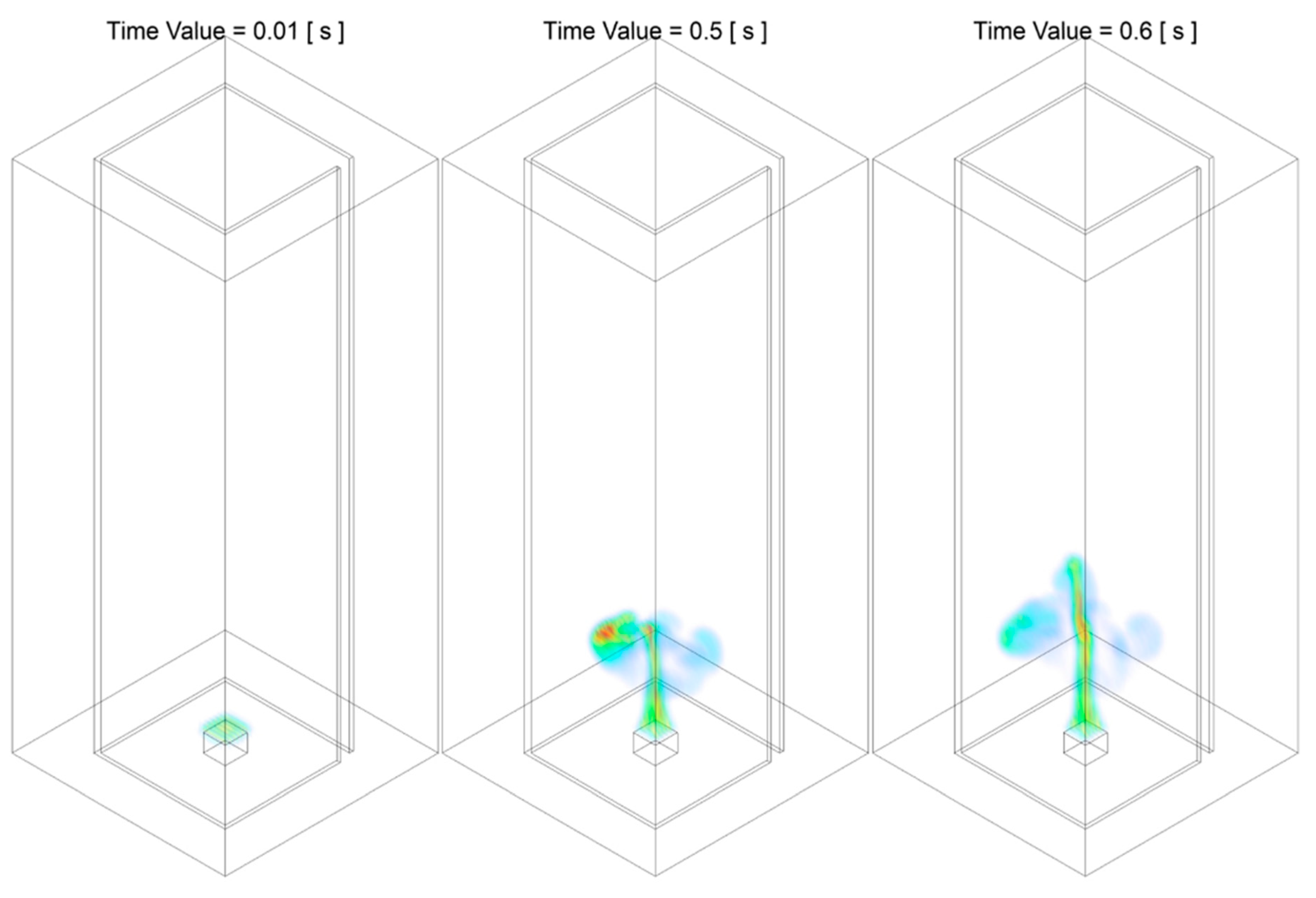
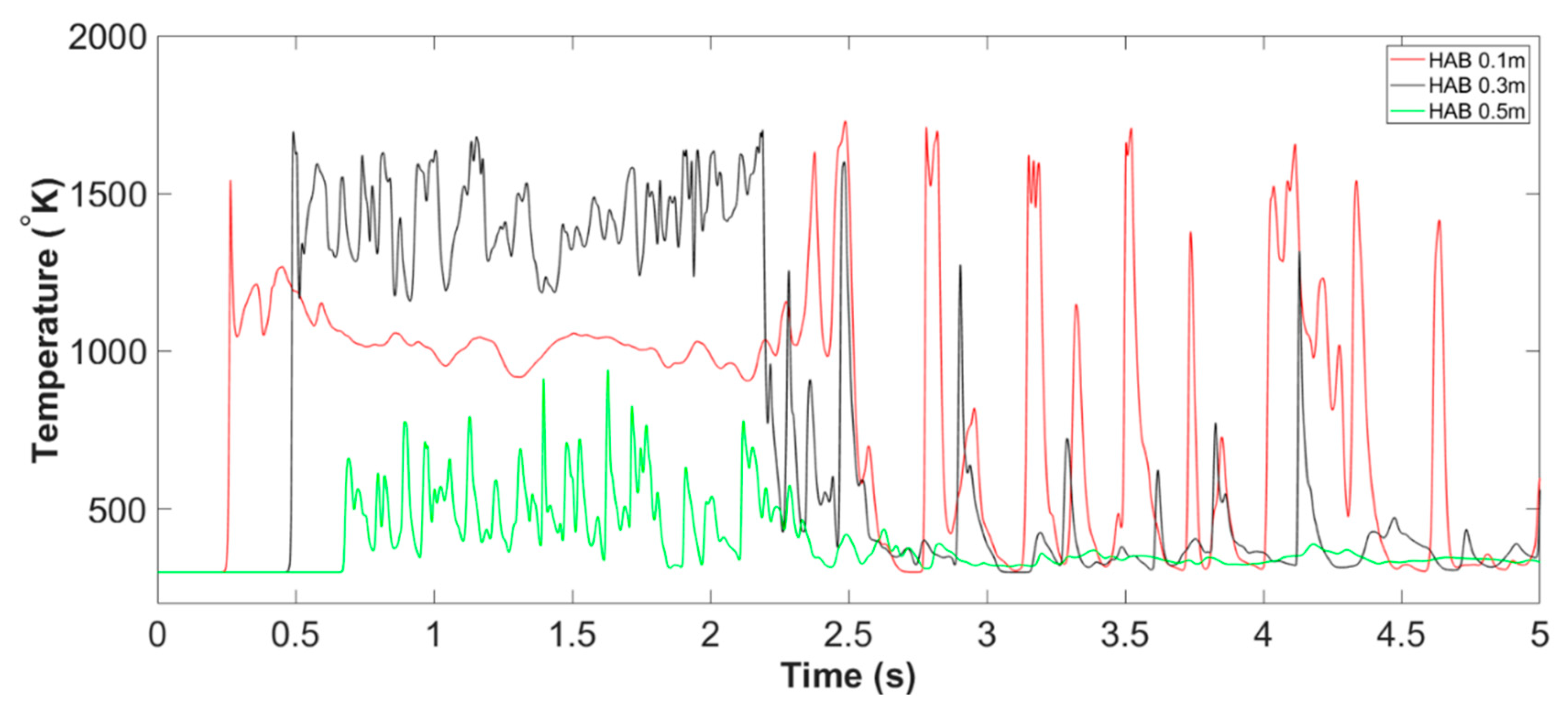
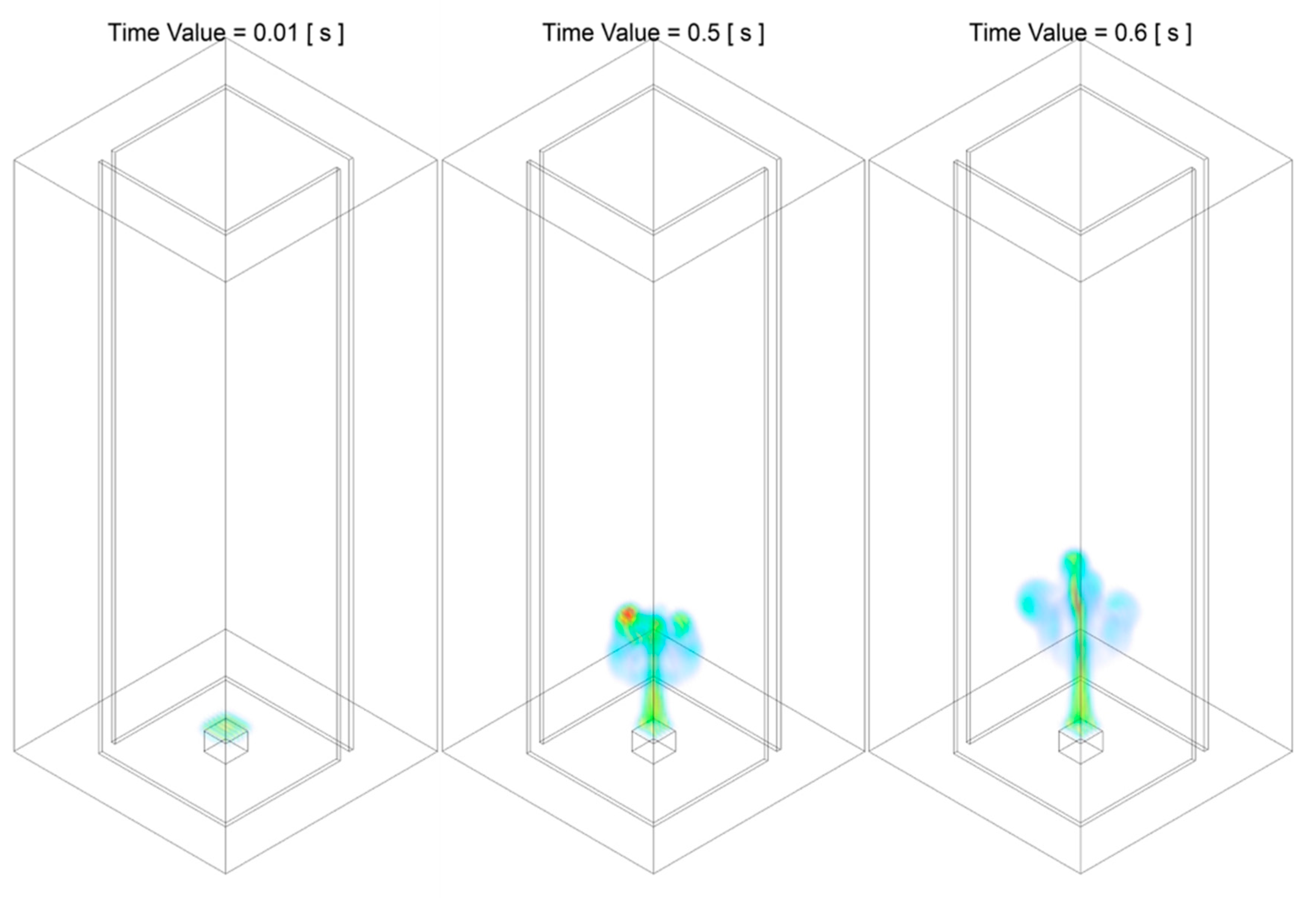
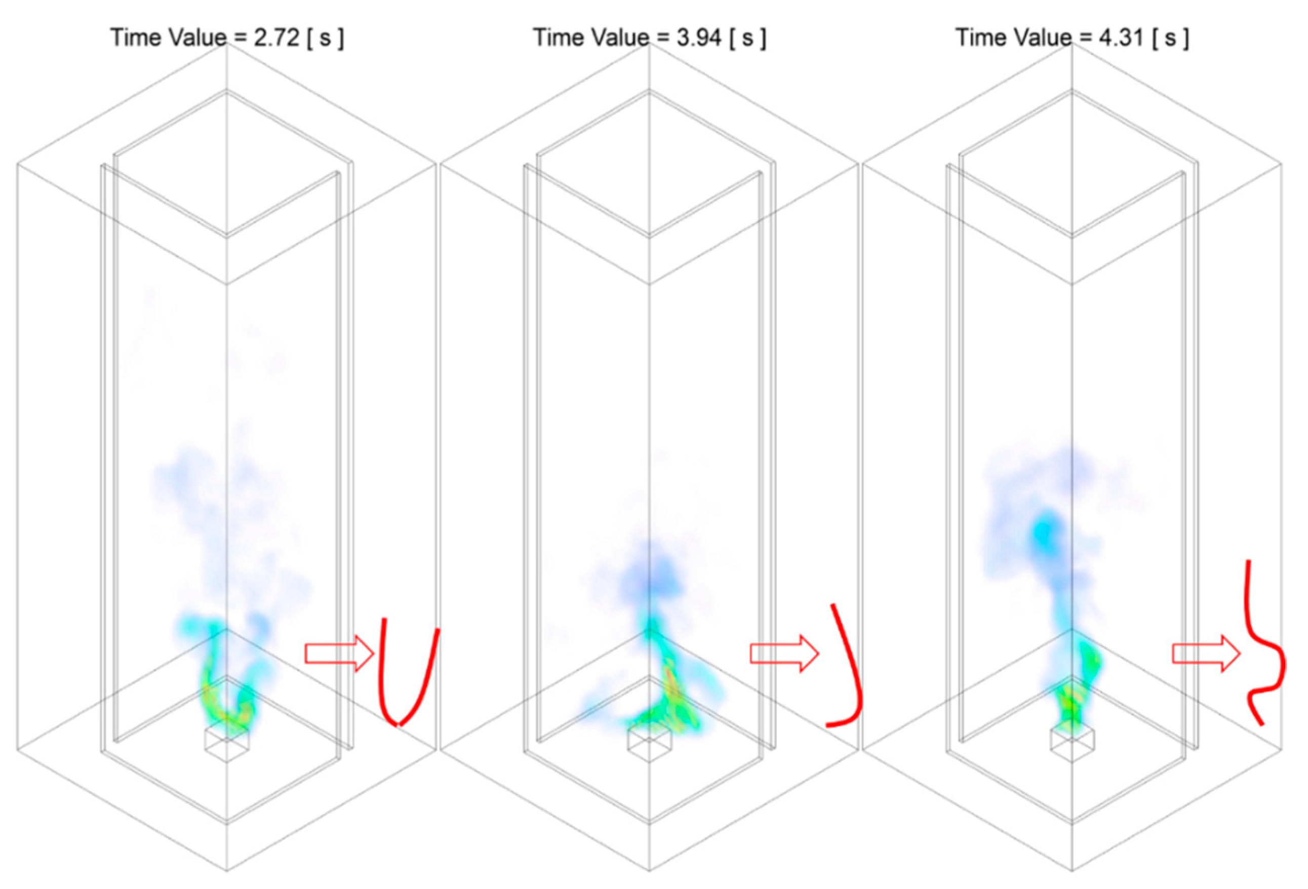
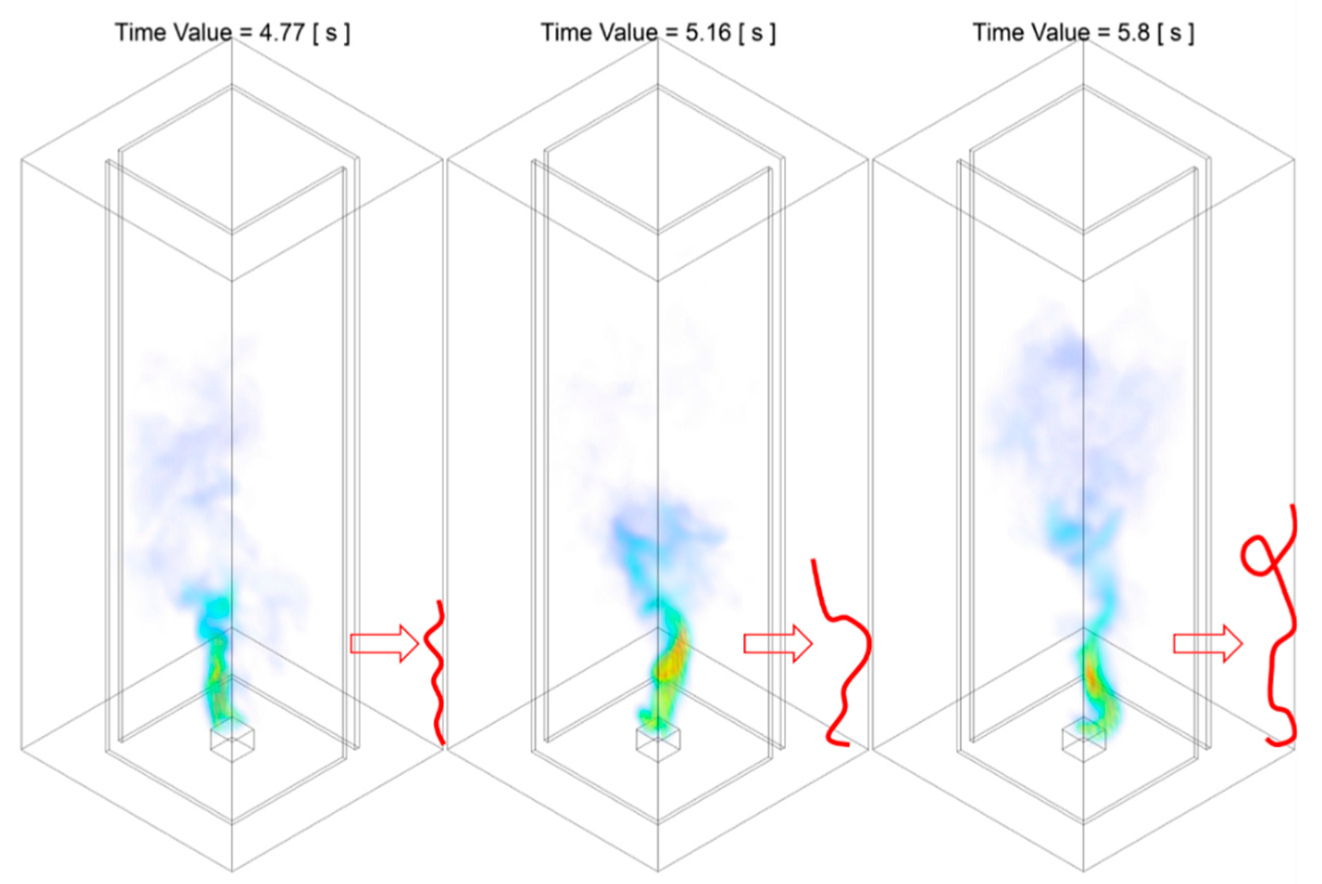
3.1.1. Stage A: Flame Development

Stage A: flame development represents the period from starting the ignition until the full development of the buoyancy-driven diffusion flame. The flame temperature in the domain centreline of all HABs of both Slit 01 case and Slit 02 case during Stage A of the combustion process are presented in Figure 5 and Figure 8. The temperature iso-surface at representative instants of time are illustrated in Figures 6 and 7, and Figures 9 and 10.
The flame temperature at domain centerline during Stage A of Slit 01 case is shown in Figure 5. Combined with the temperature iso-surface presented in Figure 6 and Figure 7, the time duration for the stage of flame development can be approximately defined as from t = 0.00   s to t = 2.55   s . The stage A could be further splitted into two periods, the period flame developing upwards from the time of ignition, demonstrated in Figure 6, and the period flame fluctuation propagates from flame tip downwards to near fuel pan surface, presented in Figure 7.
Figure 6 demonstrates a typical development of a buoyant diffusion flame during the period of t = 0.00   s to t = 0.60   s . The flame proporgates in the vertical direction, due to the dominant of momentum at the initialisation stage of the combustion. The flame front reaches the three monitoring HABs, 0.1   m ,   0.3   m and 0.5   m , at approximately t = 0.25   s ,   t = 0.50   s and t = 0.60   s .
Upon the extension of the flame height to its maximum, the flame with the straight profile starts to flicker, from flame tip and gradually propagated to the further upstream region, as demonstrated in Figure 7. It can be seen from the figure that, the region where flame starts to fluctuate starting from the flame tip at approximately t = 1.00   s , reaches the low-intermediate region at approximately t = 1.70   s and finally proporgates to near fuel pan surface at approximately t = 2.55   s . The flucturation of the flame is developing towards upstream along the domain centreline axis, as the figure demonstrated that, the flame structure that beneath the flickering region remains straight and in a relatively regulated shape. The transition of the flaming behaviour could be contributed to momentum-driven upward motion is overwhelmed by the thermo-dynamic of the buoyant diffusion upon the completion of its development. It should be highlighted that the fluctuation of the flame pattern at this particular stage is highly randomised but relatively centred with respect to the location of fuel pan, i.e., differing from the structure of a formulated fire whirl, no tendency of tilting, rotation can be observed explicitly at this instant of time.
The flame temperature at domain centerline during Stage A of Slit 02 case is shown in Figure 8. Alongside with the temperature iso-surface presented in Figure 9 and Figure 10, the time duration for this stage of flame development can be approximately defined as from t = 0.00   s to t = 2.55   s . Similar to what observed in Slit 01 case, the Stage A of Slit 02 could be further split into the flame vertical development period and flame flickering period.
As demonstrated in Figure 9, the flame develops upwards in the vertical direction during the period of t = 0.00   s to t = 0.60   s , due to the dominant of momentum at the initialisation stage of the combustion. The flame front approaches the three monitoring HABs, 0.1   m ,   0.3   m and 0.5   m , at approximately t = 0.25   s ,   t = 0.50   s and t = 0.60   s .
Nearly identical to the process observed in the Slit 01 case, as the flame puffs up to its maximum height, a region at the downstream starts to flicker and such region gradually develops downwards towards the fuel source. As illustrated in Figure 10, the region where flame starts to fluctuate starting from the flame tip at approximately t = 1.00   s , expands to the low-intermediate region at approximately t = 2.20   s and finally proporgates to near fuel pan surface at approximately t = 2.55   s . A noticeable difference of the flickering pattern observed, compared with that of the Slit 01 case, is the flame structure is relatively more symmetric. For example, by comparing the flame structure of both cases at t = 2.55   s where the region of the fluctuation reaches near fuel source surface, the flame generated from Slit 02 case is symmetrically split into two streams, with each of the streams slightly expands towards the air entrainment slit. Such well-formed symmetrical flame structure could be potentially attributed to the symmetrical air entrainment due to the two slits configuration.
In general, during the stage of flame development, the flame developing pattern of both Slit 01 case and Slit 02 case are nearly identical and resembles what expected for a typical free-standing diffusion flame in an enclosed configuration. At this stage, the entrainment air introduced from the slit(s) has not started to influence and alter the general flame propagation process.

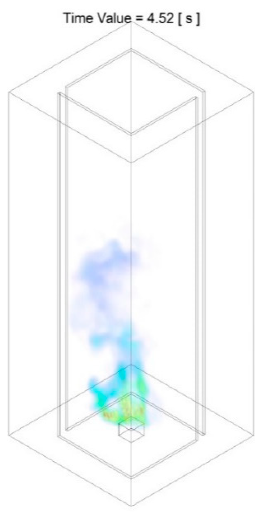
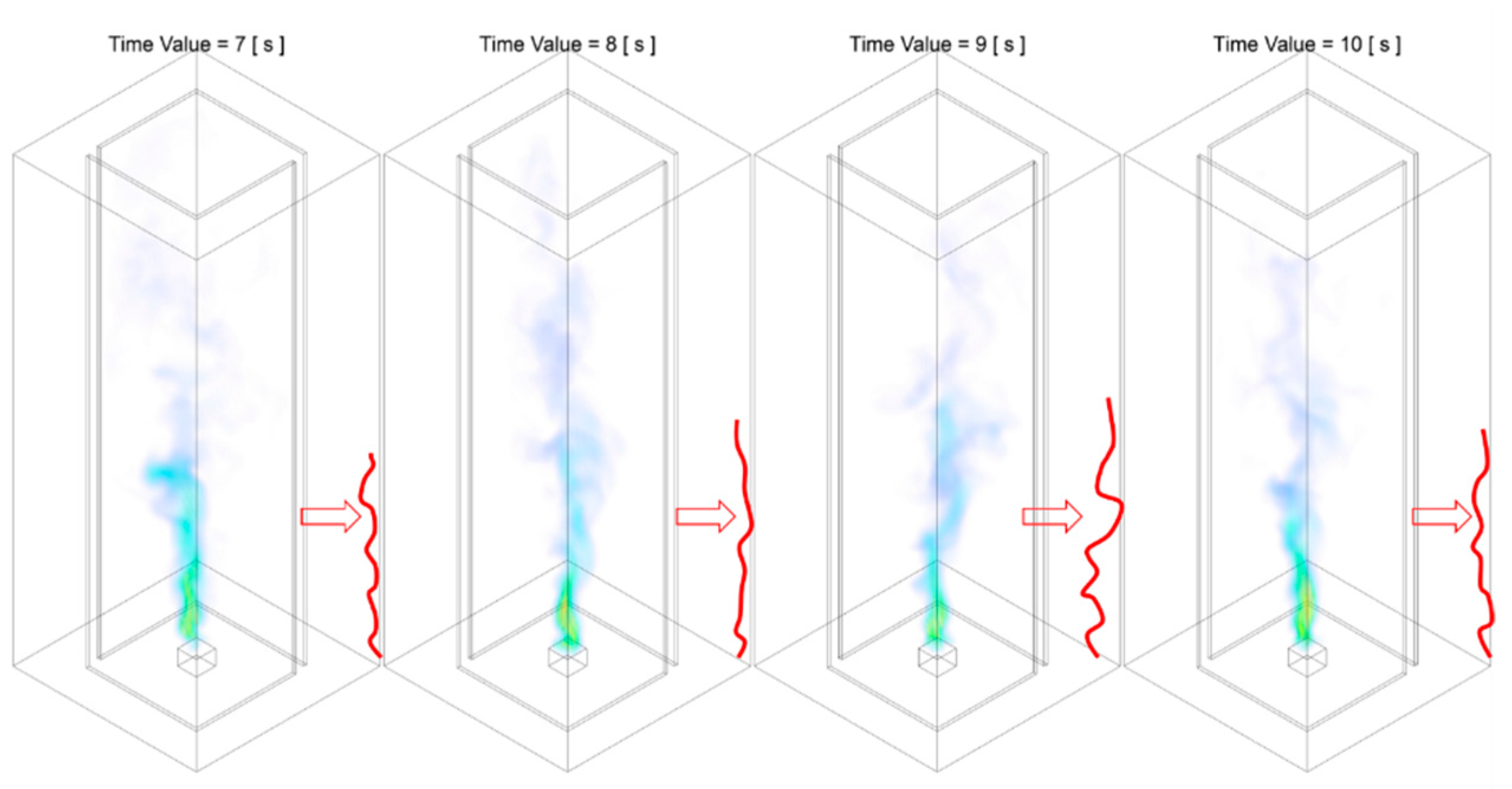
3.1.2. Stage B: Fire Whirl Development and Formation

The transition period from the flame flickering in a randomised manner to the formation of nascent fire whirl is categorised as Stage B: fire whirl development and formation. The flame temperature in the domain centreline of all HABs of both Slit 01 case and Slit 02 case during Stage B of the combustion process are presented in Figure 11 and Figure 15. The temperature iso-surface at representative instant of time are illustrated in from Figures 12–14 and from Figures 16–18.
The flame temperature at domain centerline during Stage B of Slit 01 case is shown in Figure 11. Combined with the temperature iso-surface presented in from Figure 12, Figure 13 and Figure 14, the time duration for the stage of fire whirl development and formation can be approximately defined as from t = 2.55   s to t = 8.50   s . Stage B could be further splitted into two periods, the period of transition from randomly flickering flame to the emerging of rotating reacting flow, presented in Figure 12 and Figure 13, and the period of formation of nascent fire whirl, shown in Figure 14.
The first transition period of Stage B from a flickering flame to the emerging of rotating reacting flow is can be approximately defined from t = 2.55   s to t = 6.00   s . As demonstrated in Figure 12, during the transition period, the flame started from flame tilting towards one side in a relatively straight line form, i.e., at t = 3.08   s . It follows by the transformation into that flame tilting towards one direction in the low-intermediate region and bending toward the opposite direction in the downstream region, i.e., at t = 3.66   s . It should be noted that, up to this instant of time, the profile of the lower-intermediate flame core structure as well the downstream plume tilting in the reverse direction all resembles a straight line in an L-shape, with no rational or twisting motion observed. It finally developed into the flame that tilting in one direction in the region close to fuel source, and bending towards the opposite direction in the intermediate region and rotating back to vertically straight in the down streaming plume region, i.e., at t = 4.57   s . At this time instant, the profile presented in a Z-shape format and indicates the formation of incipient fire whirl.
Nevertheless, it should be noted that such transition from tilting flame towards emerging of rotating reacting flow as demonstrated in Figure 12, is not perpetual, and could be revolved back to the previous stage at any instant of time during this period. For example, as presented in Figure 13, after the emerging of rotating reacting flow at t = 4.57   s , the flame shape becomes irregular and flucturate randomly, as a typical flame observed in Stage A during the second period of flame flickering.
The emerging of the incipient rotating reacting flow indicates the starting of the second period of Stage B, the formation of nascent fire whirl, defined from t = 6.00   s to t = 8.50   s . During this period, the flame structure rapidly transformed from whirling flow rotating in a relatively large radius, i.e., at t = 6.06   s , into the nascent fire whirl that is shifting towards domain centreline with reduces rotating radius and increased flame height, i.e., at t = 7.45   s , and eventually developed into a fire whirl that is centred with respect to fuel source and confined with a relatively small rotating radius, i.e., at t = 8.15   s . Unlike of that observed in the first period of Stage B, during this period, the evolution of the fire whirl will not be revolved back to the previous stage, and the formulated fire whirl remains in a quasi-steady state.
It should be highlighted that the domain centreline temperature of all monitoring HABs during the first period, is relatively low, i.e., near-ambient condition, compared with that of Stage A. This agrees well with the abovementioned description made based on temperature iso-surface, as the flame at this stage are likely to be tilting away from the domain centreline, thus resulting the observed low-temperature profile at all HABs. The raise in centreline temperature starts as the transition moves to the second period, which is again consistent with the tendency that the core structure of the flame is shifting towards domain centreline with reduced rotating radius and extended flame height.
The flame temperature at domain centerline during Stage B of the Slit 02 case is shown in Figure 15. Alongside with the temperature iso-surface presented in from Figure 16, Figure 17 and Figure 18, the time duration for this stage of flame development can be approximately defined as from t = 2.50   s to t = 5.50   s . Similar to what observed in Slit 01 case, the Stage B of the Slit 02 could also split into two period, the period of transition from randomly flickering flame to the emerging of rotating reacting flow, presented in Figure 16 and Figure 17, and the period of formation of nascent fire whirl, shown in Figure 18.
As illustrated in Figure 16, the three-phase transition pattern previously demonstrated in the Slit 01 case, is observed in Slit 02 case. The three-phase transition pattern can be identified as: flame tilting towards one side with relatively straight line format, i.e., at t = 2.72   s ; flame tilting towards one direction in the low-intermediate height and bending towards the opposite direction in the downstream, i.e., at t = 3.94   s ; and the emerging of the rotating reacting flow with zigzag flame structure in the low-intermediate region and straight in vertical direction in the plume region, i.e., at t = 4.31   s .
Despite the general agreement with that observed in the Slit 01 case during this transition period, there are some noticeable difference need to be highlighted. Firstly is the difference regarding the flame tilting in a straight line yield at t = 2.72 s compared with that of Slit 01 case. It can be seen that the flame is split into two streaming and tilting towards the respective air entrainment slit, compared with that tilting towards one side demonstrated in Slit 01 case. This symmetrical tilting pattern again could be potentially attributed to the symmetric geometrical configuration of the Slit 02 case. The second noticeable difference is the reduction in the first transition period in Stage B, which has a duration of approximately 2.00   s , which is reduced by 46.67 % compared with that of Slit 01 case.
Similarly, during the first transition period, the transition has not been settled. In other words, the evolvement towards the regulated swirling motion could revolve back to the previous stage at any time instant. As demonstrated in Figure 17, the flame transformed from that resemble the initial inception of the reacting flow back to the flickering flame as typically observed in Stage A.
As the flame evolves into the second period of Stage B, the formation of nascent fire whirl, defined from t = 4.55   s to t = 6.00   s , the flame structure swiftly transformed from a swilling flow with relatively large rotating radius into a semi-stabilised fire whirl that spinning with the respect of the centre of fuel source within a confined cylindrical region with extended flame height. Likewise, the duration of the second period is calculated as 1.45   s , reduced by 42.00 % compared with that of the Slit 01 case.
In regard to the characterisation of the domain centreline profile, it presents a significant difference compared with that of the Slit 01 case. Unlike the flat temperature profile reported in the baseline case, the rise of temperature in domain centreline appears at a much earlier instant of time. The temperature profile agrees well with the aforementioned reduction of duration for the first and second period. This indicates that with the introduction of the additional air-entraining slit and the resulted symmetrical side co-flow profile, the transition from a free-standing flame into a nascent fire is accelerated. The flame structures during the transition period are more likely to be positioned around domain centerline, due to the symmetrical geometrical configuration.
Generally speaking, during the stage of fire whirl development and formation, both cases share the same transmission patterns. The most significant differences observed in Slit 02 case can be summarised as the 49.58 % reduction in the overall duration of Stage B, and the relatively symmetrical flame shape compared with that of the Slit 01 case.

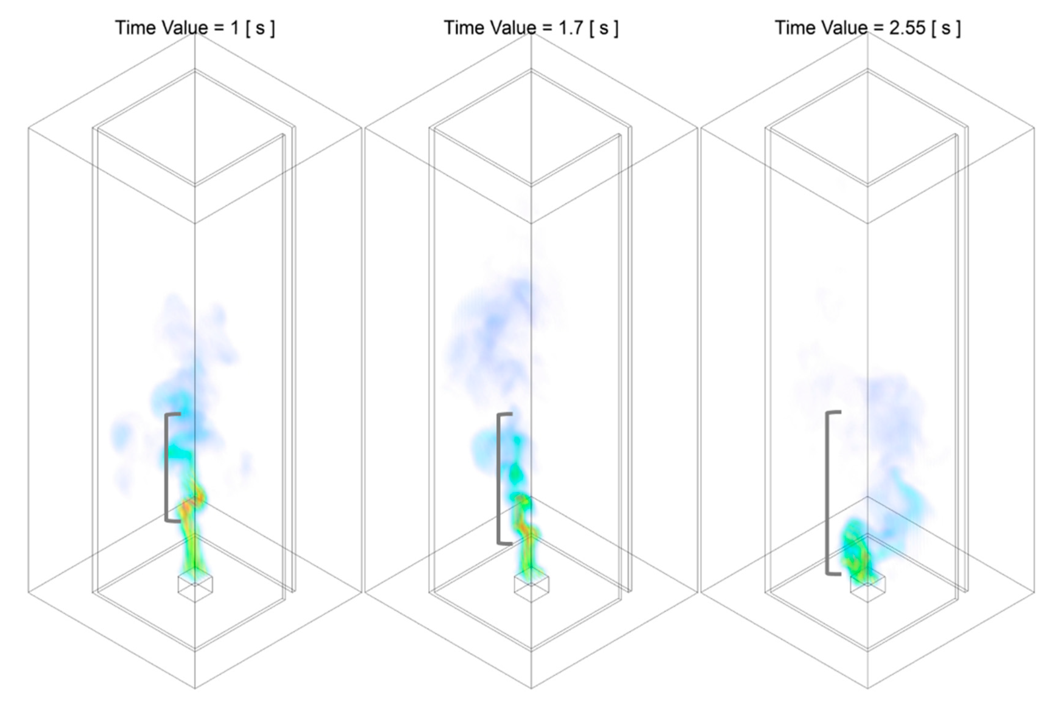
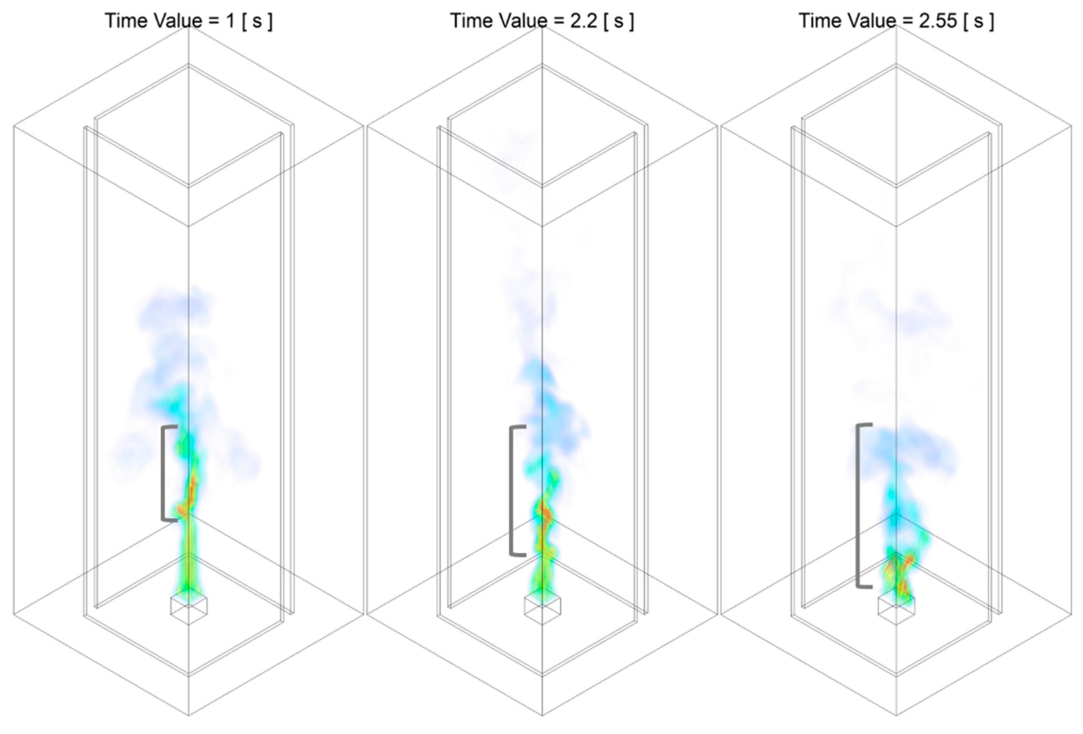
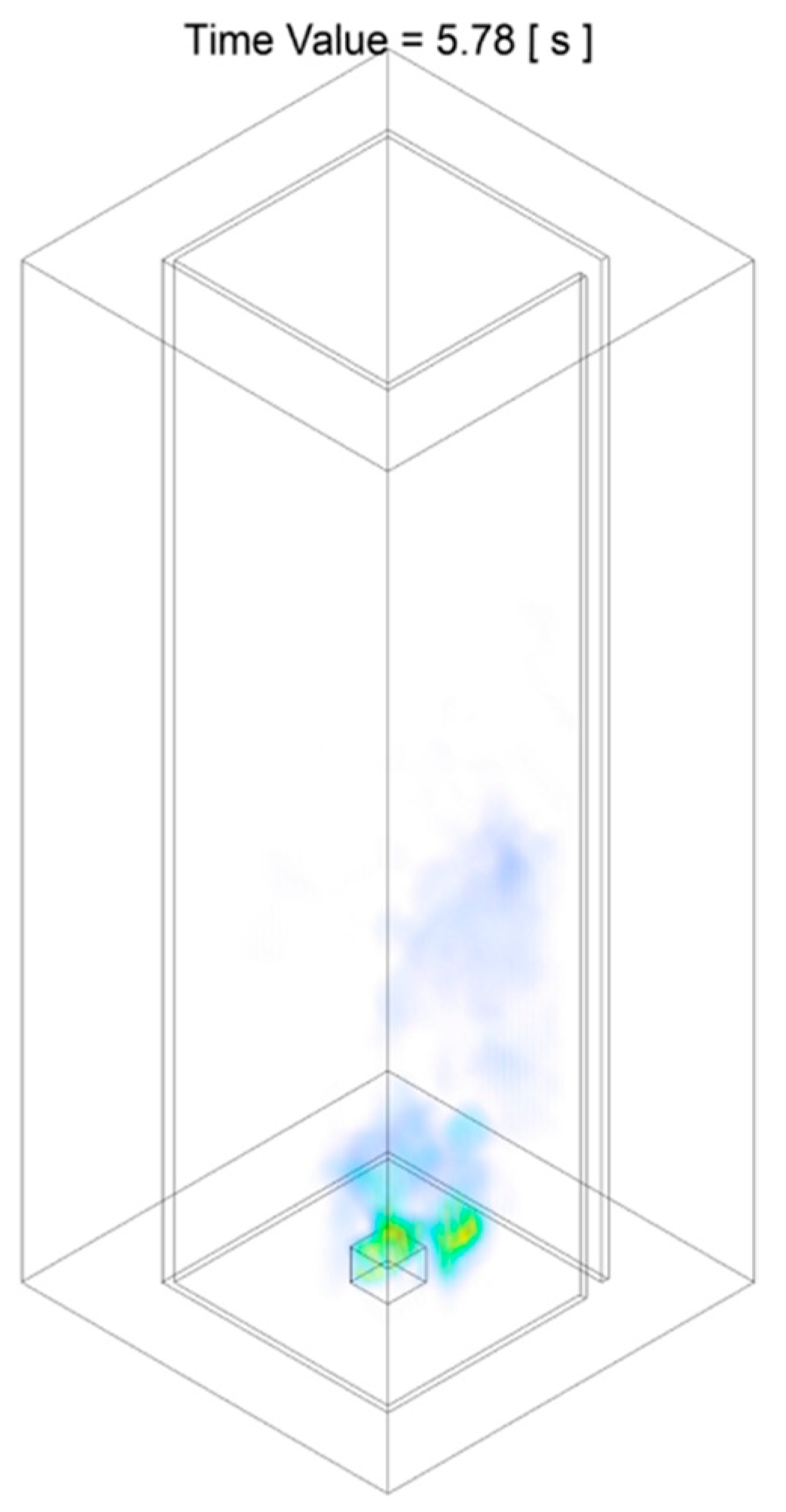
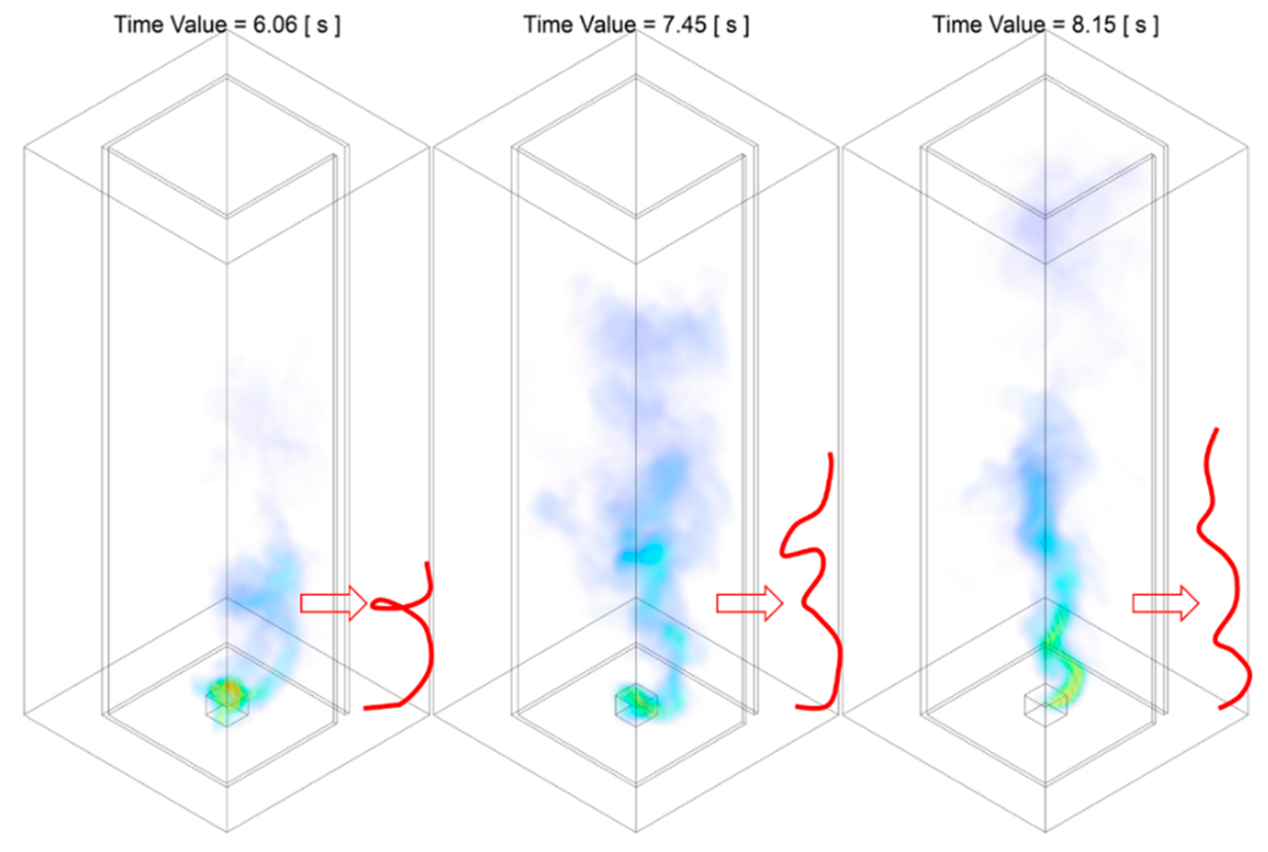
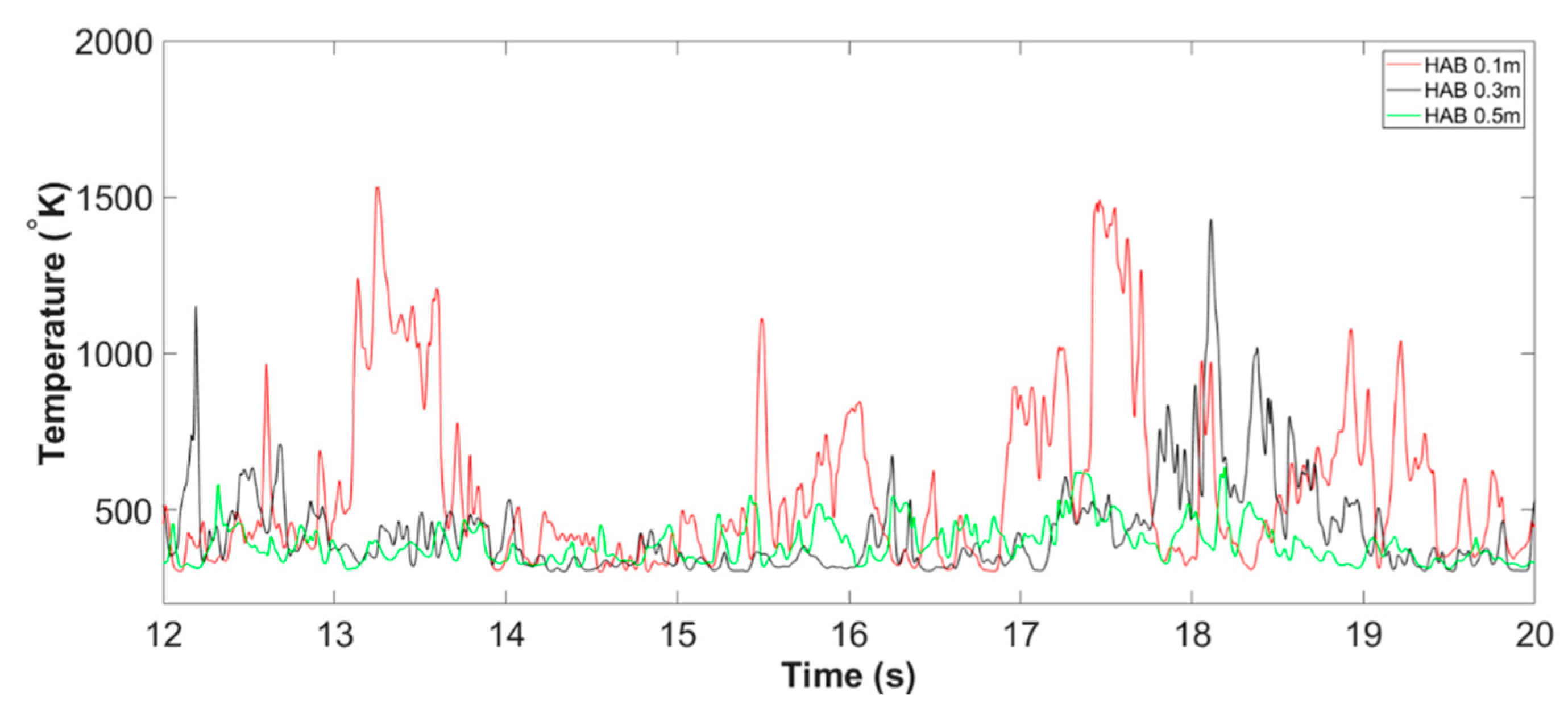
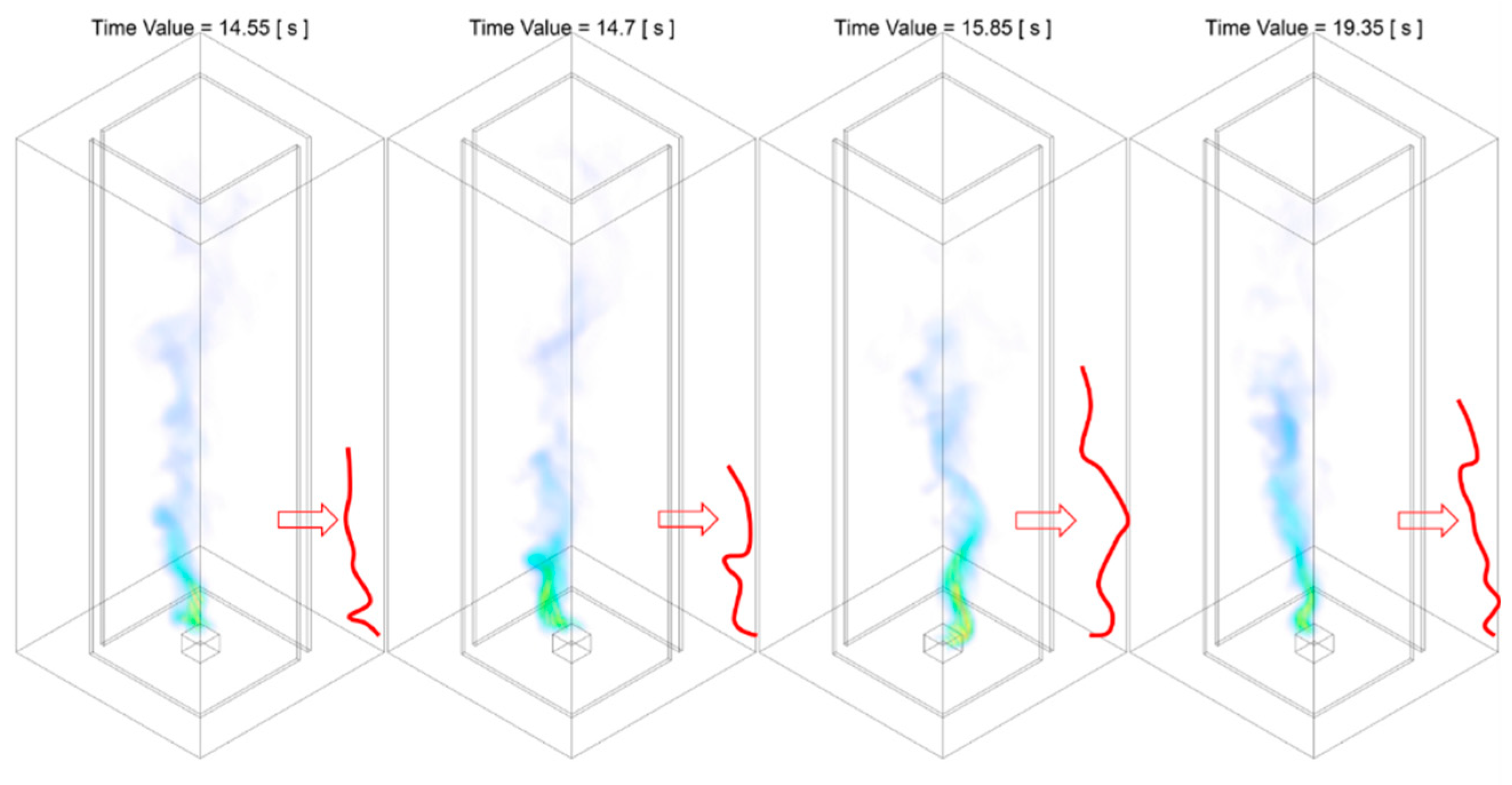
3.1.3. Stage C: Fire Whirl Evolution

The instant of time that post-formation of the nascent fire whirl is herein defined as Stage C: fire whirl evolution. Prior to the detailed analysis of the evolution of the fire whirl, the characterisation of the formulated nascent fire whirl formulated in both Slit 01 case and Slit 02 case is firstly presented and discussed.

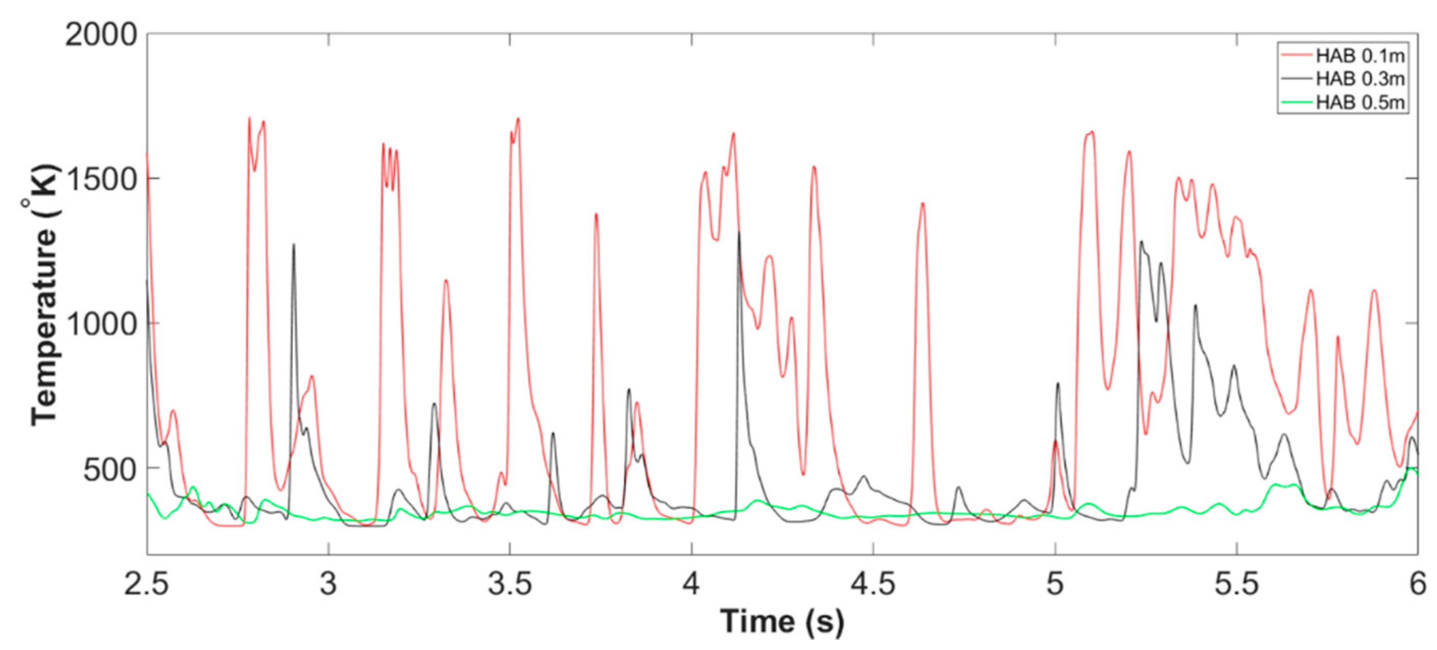
Characterisation of the Formulated Fire Whirl

With the formulation of the nascent fire whirl after Stage B, assorted key parameters have been generated to assessed to compare the characteristic of the swirling reacting flow generated by the two cases. A quantitative assessment of key parameters of both flow dynamic and combustion perspectives of the formulated fire whirl has been described in detail in the co-published work [49], and hence for the sake of brevity, would not repeat herein. In summary, it could be concluded that, the nascent fire whirl formulated under stronger eddy-generation mechanisms, i.e., domain with two slit configuration, has elongated, constrained swirling combustion region, compared with that generated in the single slit baseline model. As illustrated in Figure 19, the visible flame height with cut off flame tip temperature of 600   ° K , as well as the peak flame temperature of the core structure of the swirling reacting flame formulated in Slit 02 case increased from 0.32   m to 0.59   m by 84.38 % and from 1380   K to 1510   K by 9.42 % , respectively, when compared with the baseline. Meanwhile, the axial velocity, axial velocity dominant region of the fire whirl core structure of the Slit 02 case increased by 6.81 % and by 46.14 % when compared with the single slit counterpart. In addition, the vortex core structure, determined by flame temperature as well as evaluated based on velocity field, of the fire whirl generated in Slit 02 case remains relatively unchanged through all monitoring HABs, compared with that increased by 153.33 % and 136.91 % observed in the Slit 01 case.

Evolution of Fire Whirl

The flame temperature at domain centerline during Stage C: evolution of fire whirl of Slit 01 case, can be defined as from the inception of nascent fire whirl till the end of the simulation, i.e., from t = 8.50   s to t = 50.00   s . It can been seen from Figure 3 that, the flame temperature at the domain centreline appears to fluctuate and repeat in a periodic manner, indicating a quasi-steady state of the status of the formulated fire whirl. Such status could be confirmed by inspecting the temperature iso-surface of the four representative instant of time during Stage C, as illustrated in Figure 21.
A selective section of the period of Stage C, i.e., from t = 10.00   s to t = 20.00   s is presented in Figure 20. Unlike the flat temperature profile reported in Stage B due to the flame tilting, the centreline flame temperature in Stage C appears to fluctuate periodically. To be more specific, there are approximately four peaks in every five seconds can be observed to occur repeatedly. The pattern of the peak in centreline flame temperature could be correlated to the frequency of the revolution of the spinning motion associated with the fire whirl.
The characterisation of the fire whirls formulated presented in Figure 21 are almost identical in terms of visible flame height, flame temperature, core radius, and the frequency of the revolution, etc. Such similarity in the characterisation of fire whirls persists during the entire Stage C till the end of the simulation. It could be, therefore, conclude that, the fire whirl formulated by Slit 01 case has reached semi-steady state during Stage C.
Differ from the flame centreline appears in a repeated pattern of the baseline case, the centerline flame temperature of Slit 02 case varies significantly during Stage C. As demonstrated in Figure 4, the occurrence pattern of relative high flame temperature at the domain centerline transformed from appearing intensively to occasionally and the temperature profile eventually becomes flat. It is, therefore, reasonable to subdivide the Stage C of Slit 02 case into separate periods and investigate the characterisation of each period individually.
The first period of the fire whirl evolution, Stage C 1 , of the Slit 02 case is characterised as the period when the raise of domain centerline occurs frequently. From the observation of Figure 4, such period can be identified as from t = 6.00 s to t = 12.00 s, and the centerline temperature profile at all monitoring HABs is plotted in Figure 22. It is apparent that, by compared with that of Stage C of the Slit 01 case report previously, the occurrence of peak temperature at the domain centerline is observed to be more recurrent. For example, compared with peaks three or four times in every five seconds in the baseline case, the pattern of temperature rise at centerline demonstrated a two to three peak occurs in every second. This trend is more predominant during the period between t = 7.50 s to t = 9.00 s, where the centerline flame temperature at HAB 0.1   m remains roughly constant at a maximum value. This observation agrees well with the previous analysis in comparing the nascent fire whirl formulated in both cases. Due to the intensified eddy-generation mechanism from the second entrainment slit, the nascent fire whirl generated in the Slit 02 case is more spatially centralised in a confined space in the vicinity of domain centerline as well as with a more extended flame height, and thus persists with a relatively smaller radius and leads to higher centerline flame temperature, when compared with that of the baseline case.
At this stage, the fire whirl in a fairly stable status, as the temperature iso-surface at representative instant of time during Stage C 1 is presented in Figure 23 is nearly identical in terms of all primary parameters of interest during this period.
As the fire whirls revolving under the symmetrical and intensified entrainment configuration, it gradually moves to the second stage of fire whirl evolution, Stage C 2 : the fire whirl gradually deviates from the previously observed confined region and departs from domain centerline in an outbound direction. With a close inspection of the centerline flame temperature profile as well as the temperature iso-surface at representative instant of time, presented in Figure 24 and Figure 25 respectively, the time duration of the Stage C 2 can be defined as from t = 12.00   s to t = 20.00   s . From the observation of flame centerline temperature, it can be concluded that the occurrence of a temperature peak at domain centerline are tending to become scatted during this period, compared with that reported in the Stage C 1 , i.e., the frequency of the flame temperature peak at the domain centerline reduced from two to three appearances every second into approximately three appearances in every five seconds, which resembles the nascent fire whirl formulated in the baseline case.
The reduction in the frequency that high flame temperature arises at the domain centerline could be explained by assessing the iso-surface of representative instant of time during this very period. It can be seen from Figure 25 that, over time, the lower-intermediate region, as well as the downstream plume region of the fire whirl, starts to deviate from the confined space that observed in previous period and departs from domain centerline towards the enclosure. The flame core region where high temperature persists is less likely to sweep across the domain centerline and result in the temperature rise compared with that of Stage C 1 . It should be noted that there are two unique features of the flame structure of the fire whirl generated in this very period. Firstly, despite deviating from the domain centerline, it increases in cone radius, and the tilting or bending occurs limited at the elevated height close to the fuel source, i.e., near the bottom boundary, with the downstream region of the flame remains relatively straight. Secondly, despite the fact that the flame core structure is tilting towards the domain enclosure, the entire region of combustion, including the flame core as well as the plume is observed to be spinning and remains a fairly regulated cylindrical shape, which is fundamentally different from that observed in Stage B, i.e., tilting file during fire whirl development and formation.
The flame core region keeps departing from the domain centerline as the fire evolution progresses into the final period, Stage C 3 : the core structure fire whirl continued to deviate from domain centerline and eventually settles as it swilling in a relatively large radius at regions closed the domain enclosure. The duration of this period can be defined as from the completion of Stage C 2 till the completion of the simulation, i.e., from t = 20.00   s to t = 50.00   s .
The flame centerline temperature profile, as well as the temperature iso-surface at representative instant of time, is plotted in Figure 26 and Figure 27. From the observation of the figures, there is evidence that the flame core region continues to deviate from the domain centerline and rotates with respect to the fuel source in a relatively large radius. The departing from the domain centerline of the fire whirl core structure leads to a flat centerline temperature profile at all monitoring HABs, resembles what was observed in Stage B as the flame is tilting. Similar to that noticed in Stage C 2 , the intermediate and plume region of the fire whirl remains relatively upright straight, and the tilting and bending region are limited to low HAB where close to the bottom boundary. The flame structure is also different from tilting flame as strong rotational motion at any part of the flame can be observed.
It should be highlighted that the departure from the domain centerline or increases in core radius will ease as the core structure of the fire whirl approaches the domain boundary and is constrained by the enclosure. Up to this stage, the fire whirl is reaching a quasi-steady state and such revolution behaviour is observed to remain till the end of the simulation.
It should also be noted that the results presented herein are limited to describing the characterisation of the formulated fire whirl at various time instances based on their development stage. The potential causes for such behaviour, including that such a flame remained relatively steady in Slit 01 case but departed away from the centerline and eventually rotated in a relatively large radius in Slit 02 case, is discussed in detail in the following section.

3.2. The Potential Causes of the Observations

It is also commonly agreed upon that the pressure deficit between the environment and cyclone eye is expected in a typical air spinning scenario. Similarly, the velocity vector field gives an indication of the magnitude as well as the approximate size of the vortex region, i.e., that with strong rational motion. Pressure contour and velocity vector field of both cases are therefore generated and presented to further assess flaming behaviour and transition during fire whirl evolution and as a probe for potential causes. Based on the observation from the previous section, it appears that the region where fire whirl tilting and deviating from the domain centerline occurred was in the low HABs region, i.e., near the bottom boundary, whereas the downstream of the fire structure remained relatively upright straight. The pressure contour and velocity vector field at the selected instant of time, therefore, is limited to the lower monitoring HAB, i.e., HAB 0.1   m , for both the Slit 01 case and Slit 02 case. It should also be noted that the representative time instant is selected based on when the incoming velocity of the air-entraining slit, at its maximum, minimum and at one time instant in between. The location of the vortex core of the fire whirl, determined collectively from assessing the pressure and velocity, is subsequently recorded and transferred to generate the revolution orbit during the revolution.
In addition, for this particular geometrical configuration of both cases, it is generally known that the fire whirl is induced by the air entrainment introduced from the slit(s). For this reason, the incoming velocity profile at HAB 0.1   m , is also presented to establish the correlation with the observed flaming behaviour and key parameters of interest.
The information of pressure, velocity at the boundary layer as well at the slit, and the pathway of orbiting, of the two cases, are collectively assessed to probe the potential causes of the observed evolving flaming behaviour.

3.2.1. The Potential Causes of Observations of Case 01

The pressure contour and velocity vector field of the Slit 01 case at HAB 0.1   m at the selected instant of time, are presented in Figure 28 and Figure 29.
The figures show that the air at the monitoring HAB is flowing from high pressure to low pressure region, i.e., drawn from surrounding to the enclosed space via entraining slit. This observation generally agrees well with the commonly agreed flaming behaviour in the fire scenario. To be more specific, a fire in the compartment is expected to grow in direct proportion to available oxygen. In a typical compartment fire, air carrying oxygen is often observed to be drawn from outside into the base of the fire through openings in the building, e.g., doors, windows, roof. The opening of the slit in the current case acting as the source of entraining air promotes the combustion process, and at the same time facilitates the movement of combustible gas mixture, and the subsequently involved flame structure, heat and smoke, from higher pressure areas towards lower pressure areas accessible openings.
The pressure contour combined with velocity vector field also indicates the relative vortex core location and the approximate size of the spinning reacting flow. It can be seen from the figures that, the size of the swirling reacting flow, as well as the rotating radius, of the fire whirl of the Slit 01 case is relatively small when compared with that of the Slit 02 case shown in from Figures 32–35. It is suggested that the core structure of the formulated fire whirl is constrained in a confined space, and is rotating in a relatively small radius with respect to the fuel pan.
The revolution orbit of the fire whirl with respect to the fuel source is obtained by transferring the location of the vortex of all time instant of interest and plotting into Figure 30. In addition, the incoming velocity of the slit of the monitoring HAB, at the corresponding time instant, is presented in Figure 31. The location of the fire whirl core is indicated by the Applsci 10 00318 i001 
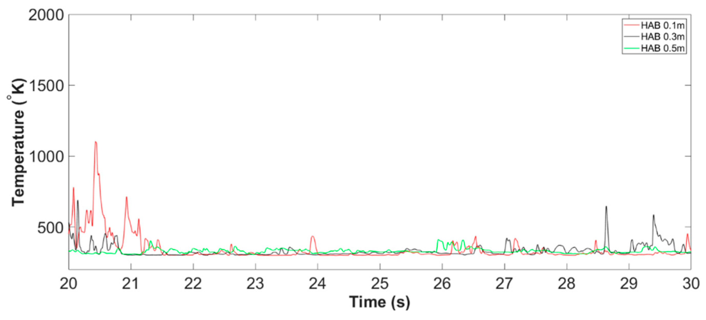
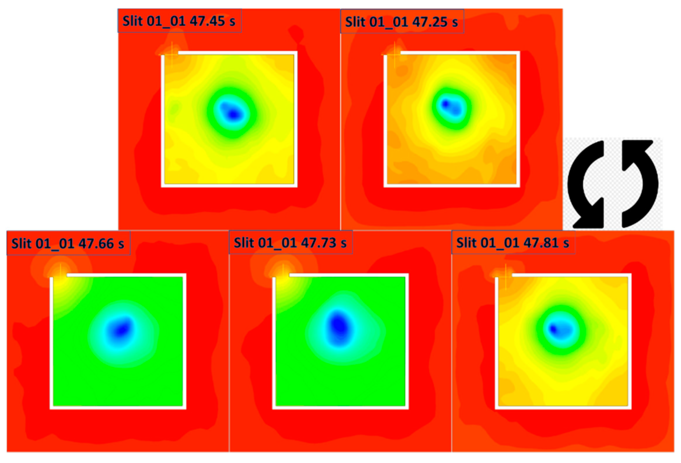
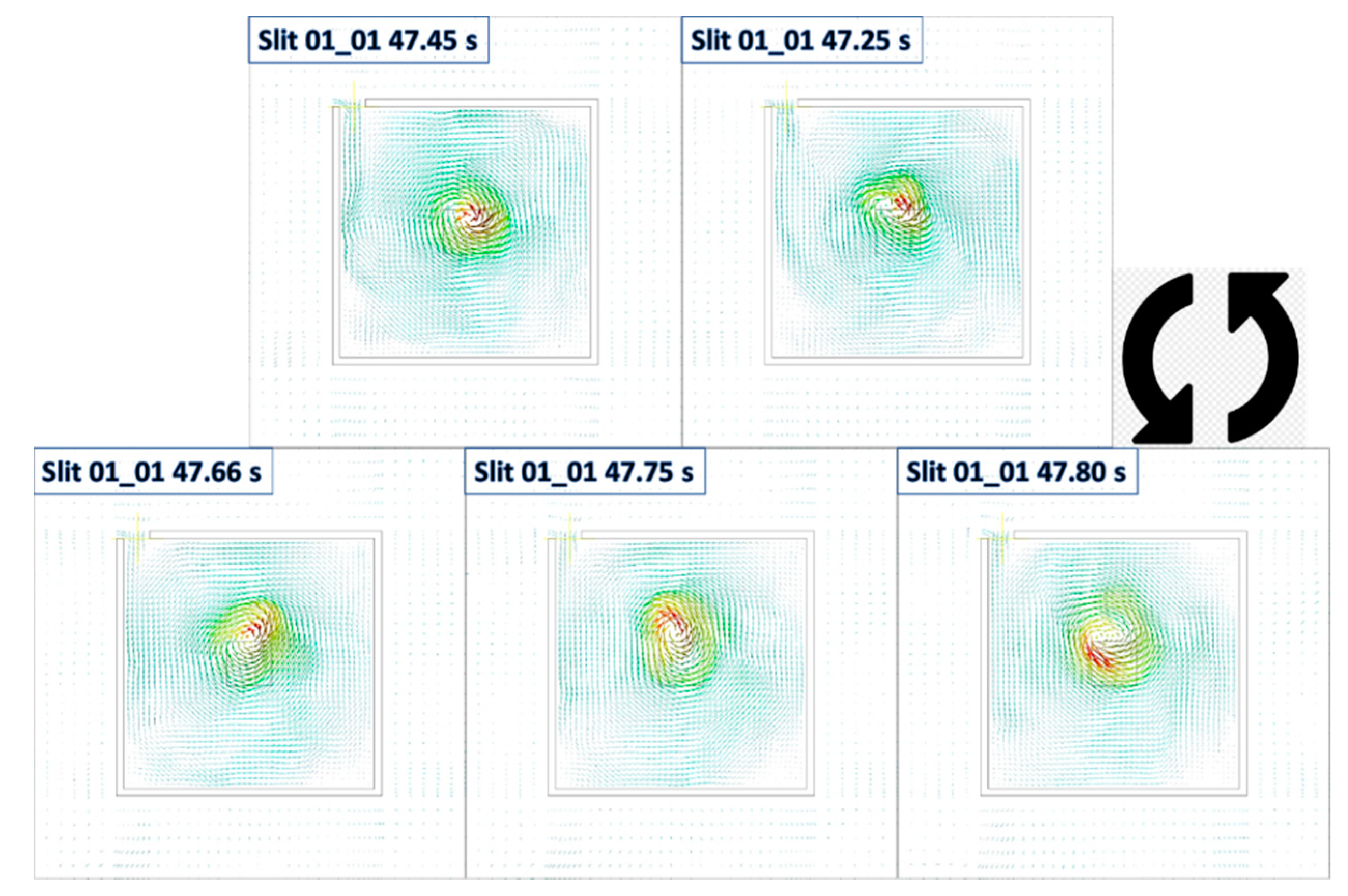
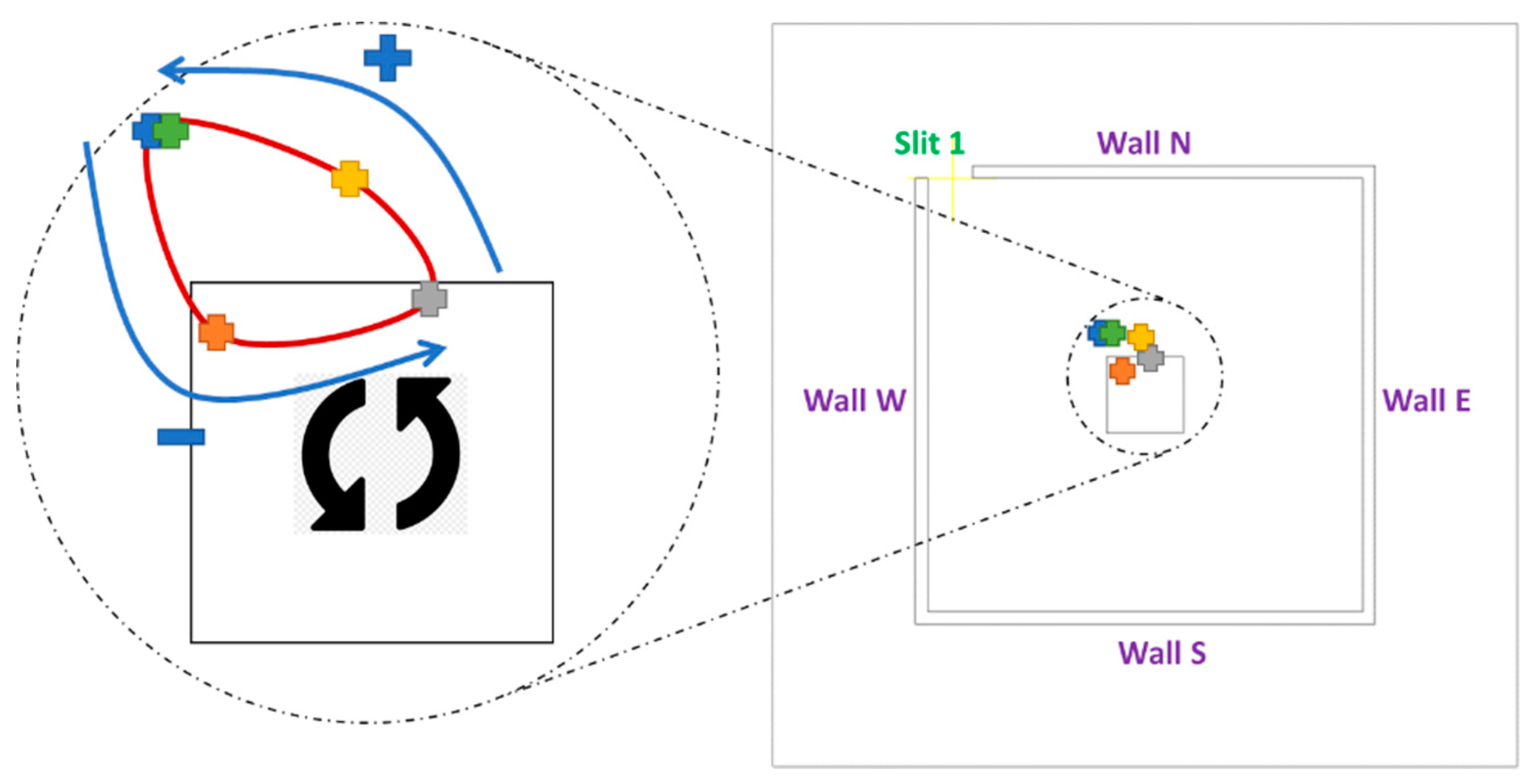
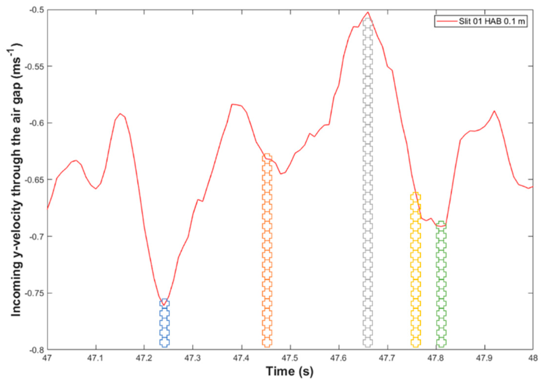
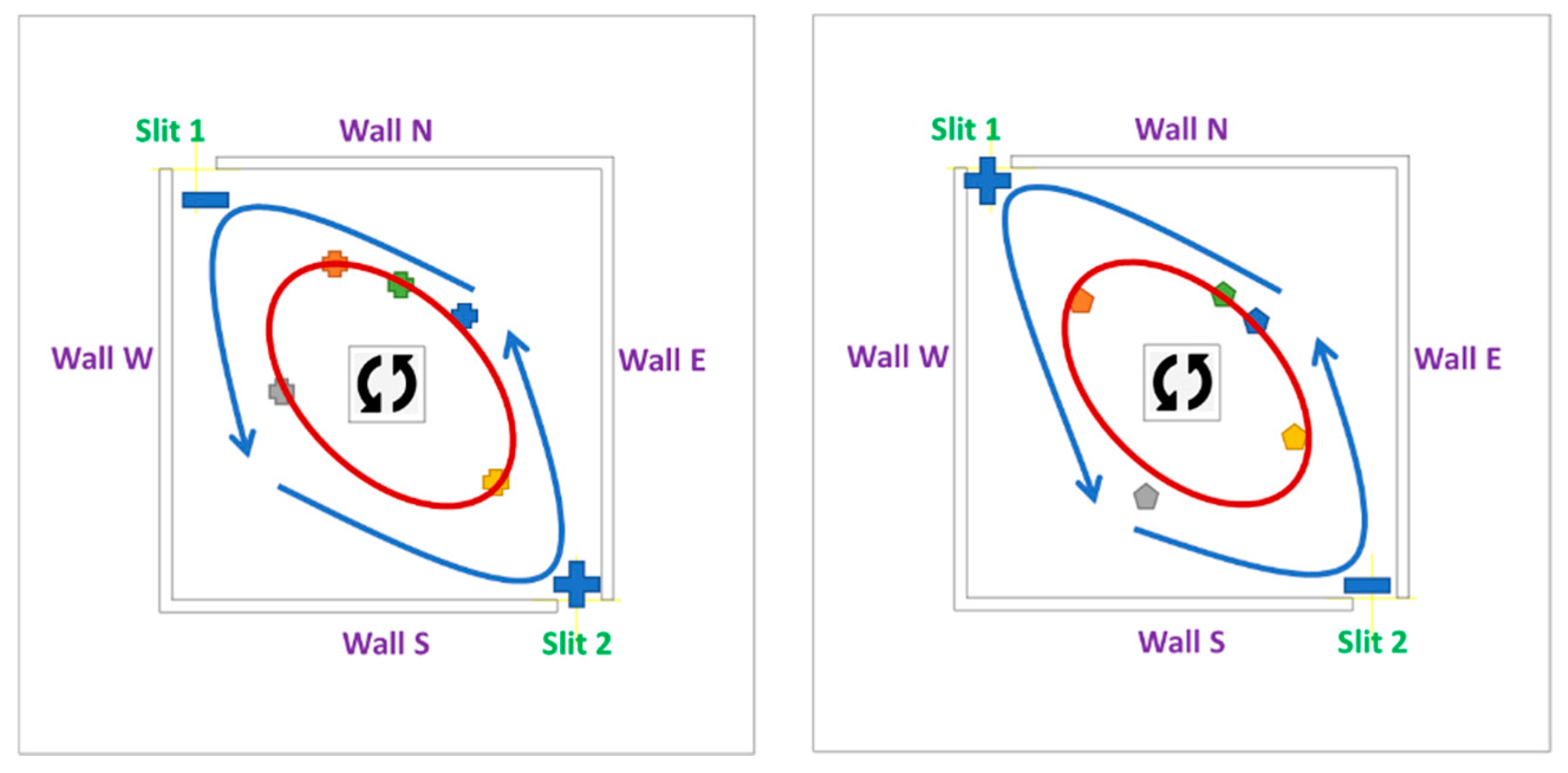
in various colour, in both figures.
From Figure 30, it can be seen the anti-clockwise revolution orbit of the fire whirl of the Slit 01 case, starting from Applsci 10 00318 i002, and ending with Applsci 10 00318 i003, is not in a shape of a regular circle. It appears the vortex core location deviates from domain centerline as it approaches the entrainment slit, and restores to the near fuel source location as it moves away from entrainment slit. To be more specific, for the fire whirl originated from the fuel pan centre, the rotating radius can be defined as the distance between the vortex core and the fuel pan centre. It can be observed that, from time instant of t = 47.25   s ( Applsci 10 00318 i002 ) to t = 47.45   s ( Applsci 10 00318 i004 ), the fire whirl is rotating anti-clockwise from northern wall region to western wall region and moves away from the air entrainment slit. The rotating radius decreases significantly. While from time instant of t = 47.66   s ( Applsci 10 00318 i005) followed by t = 47.73   s ( Applsci 10 00318 i006) and to t = 47.81   s ( Applsci 10 00318 i003), the fire while sweep from near eastern wall region towards near northern wall region and moves towards the air entrainment slit, the rotating radius increases significantly.
This observation could potentially be explained using the concept of the circular motion with a constant centripetal force, which can be expressed as:
F C = m v 2 r
where F C is the centripetal force towards the centre of the circle, m is the mass, v is the velocity and r is the radius of the rotation.
For a circular motion with a constant centripetal force, the radius is proportional to the square of the velocity. For the current fire whirl scenario spinning around the fuel pan in a single slit, the centripetal resembles the surface drag force to create the radial boundary layer, which can be considered as a constant, due to the fixed burning rate introduced to the domain, i.e., constant injection velocity of the parent fuel. Such a centripetal force is acting to ensure the reacting flow originated from the domain centre is spinning around the fire source.
Due to the pressure gradient, the air is entrained from the surrounding to the chamber. As the fire whirl core structure approaching the slit, the air entrainment acted as a supply source to intensify the velocity field of the flame core structure. As a result, the increase in the velocity field of the rotation reaction flow may increase its rotation radius to achieve the balance with the relatively fixed centripetal force acting perpendicular to the circle, for example, for time instant of 47.80 s ( Applsci 10 00318 i003). On the other hand, as the flame structure departing from near slit region towards where away from entrainment sources, i.e., region between northern and eastern walls such as indicated in 47.66 s ( Applsci 10 00318 i005), the intensification of the velocity field of the fire whirl eases, therefore the location of the fire whirl core structure restores back to the original near fuel pan region.
The incoming velocity of the air entrainment source, the slit, against the time, is also plotted in Figure 31, with the representative time instant denoted as Applsci 10 00318 i001.
It is obvious that the amount/rate of the air drawn into the chamber via the slit is proportional to the pressure gradient between the two sides of the slit, which is as expected. For example, with the region of the vortex with larger pressure gradient approaching the slit, the rate of air drawn into the domain is increasing, i.e., from time instant 47.66 s ( Applsci 10 00318 i005) to that in 47.80 ( Applsci 10 00318 i003), whereas the rate of air entraining rate decreases as the core of the fire moves away from the slit, such as from time instant 47.25 s ( Applsci 10 00318 i002) to that in 47.66 s ( Applsci 10 00318 i005).

3.2.2. The Potential Causes of Observations of Case 02

Similarly, the pressure contour and velocity vector field at HAB 0.1   m at the selected instant of time, is presented in from Figure 32, Figure 33, Figure 34 and Figure 35, to reveal the information of the size and radius of rotation of the fire whirl of the Slit 02 case. Herein, the time instant denoted in Applsci 10 00318 i001 
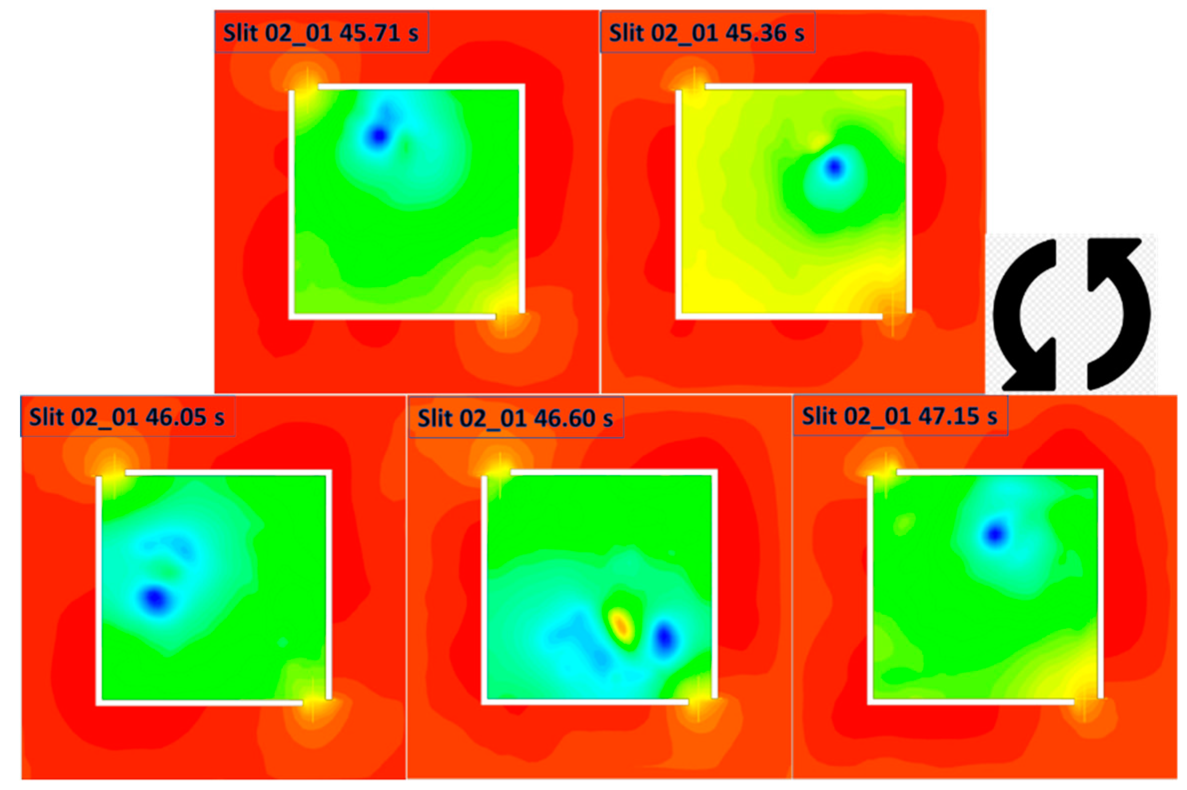
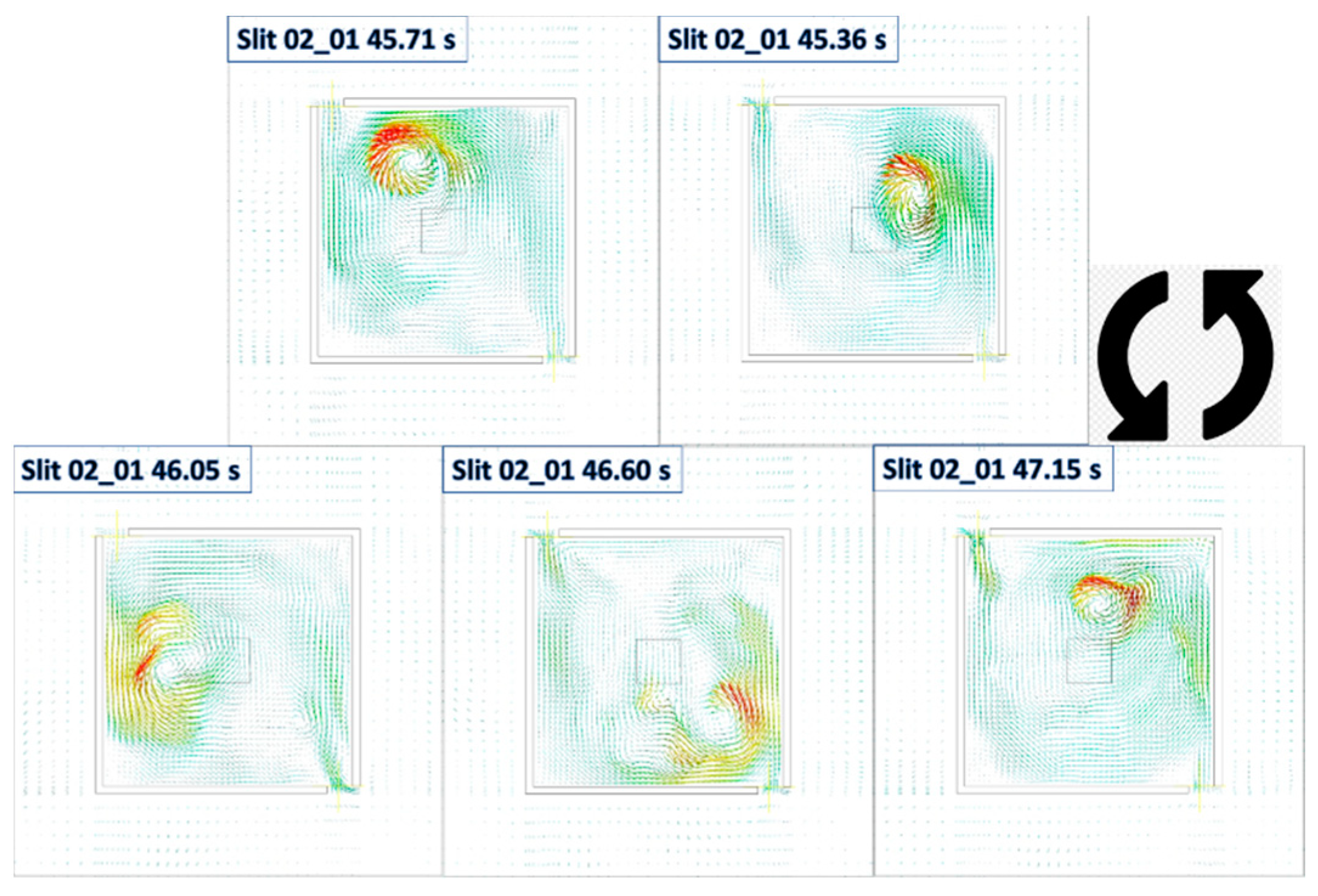
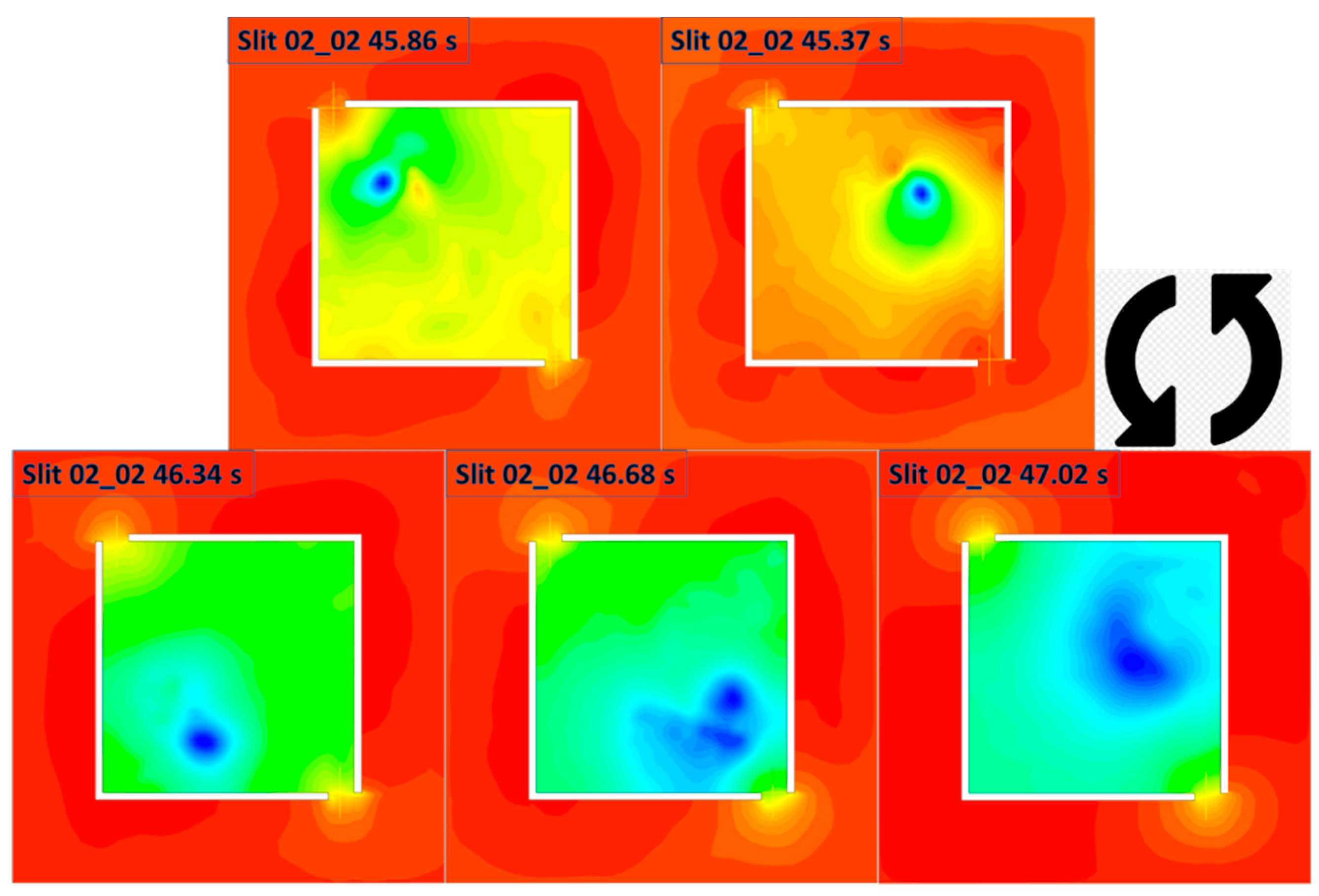
are corresponding to those the peak, bottom and median velocity instant associated with slit 01 , and those denoted as Applsci 10 00318 i008 are representative for the same time instant set associated with Slit 02 .
Through the close review of the pressure contours and velocity vector field, and compared with those generated by the Slit 01 case, some similar trends that have been seen in the baseline model can be again observed in here. For example, the air is again drawn from the surrounding to the enclosure through the slits, and the reacting flow is swirling around, with respect to the fire source in an anti-clockwise direction.
However, there is some distinct difference that can be noticed. The size of the core structure is significantly larger, and the flame structure is rotating with a large radius, with respect to the geometry domain centerline, when compared with that of the baseline case. To be more specific, the core structure of the baseline case, is in a narrow form and its circulation movement is constrained in the vicinity of fuel pan regions. On the other hand, the structure of the fire whirl formulated in Slit 02 case are circulating around the fuel source in a significantly large radius, and the size of the structure is significantly larger, i.e., it can be even observed that the shape of the swirling reacting flow is constrained and limited by the enclosed wall boundaries.
This speculation can be further justified when transferring the location of the vortex core and plotting the orbit of revolution of the reacting flow, as showing in Figure 36. The radius is further away from the fuel pan when compared with the baseline, especially when the core structure is approaching to the slits. Please note that the representative time instant associated with Slit 1 and Slit 2 denoted as Applsci 10 00318 i007 and Applsci 10 00318 i008 respectively.
The revolution orbit demonstrated in Figure 36 also agrees well with pseudo-centripetal and associated circulation motion concept proposed previously. With the vortex approaching the air entrainment supplier source, i.e., slit and the resulted intensification of the velocity field of the structure of the swirling reacting flow, the radius of the revolution increases, based on a near-constant centripetal force resembled surface drag force that creates the radial boundary layer, and vice versa. For example, when the fire whirl sweep from enclosed corner towards slits, i.e., from time instant 45.36 s ( Applsci 10 00318 i002) to 45.71 s ( Applsci 10 00318 i004), from 46.05 s ( Applsci 10 00318 i005) to 46.60 s ( Applsci 10 00318 i006), from 45.37 s ( Applsci 10 00318 i009) to 45.86 s ( Applsci 10 00318 i010), and from 46.34 s ( Applsci 10 00318 i011) to 46.68 s ( Applsci 10 00318 i012), a significant increase in rotation radius is observed. On the other hand, the centripetal force restores the orbit of the revolution by dragging the vortex structure back to the near fuel pan regions, when the fire whirl spinning from near slit region towards enclosed corner, i.e., from time instant 45.71 s ( Applsci 10 00318 i004) to 46.05 s ( Applsci 10 00318 i005), from 46.60 s ( Applsci 10 00318 i006) to 47.15 s ( Applsci 10 00318 i003), from 45.86 s ( Applsci 10 00318 i010) to 46.34 s ( Applsci 10 00318 i011), and from 46.68 s ( Applsci 10 00318 i012) to 47.02 s ( Applsci 10 00318 i013).
The incoming velocity of the air entrainment source, both Slit 1 and Slit 2 , against the time, is also plotted in Figure 37. It is surprisingly that the correlation of the distance between the fire whirl core to the slit and the incoming velocity of the slit demonstrated in the Slit 01 case can not be observed in the Slit 02 case. In contrary, the minimum incoming velocity is observed when the fire whirl core is at the closest location with respect to the slit. For example, for incoming velocity associated with Slit 01 , it can be seen that the incoming velocity decreases as the fire whirl approaches and sweep through the Slit 01 , i.e., from time instant of 45.36 s ( Applsci 10 00318 i002) to 46.05 s ( Applsci 10 00318 i005), and the incoming velocity increases as it shifted away from the slit, for example from time instant of 46.05 s ( Applsci 10 00318 i005) to 47.15 s ( Applsci 10 00318 i003). The similar tendency can be observed with relative fire whirl location with respect to the incoming velocity associated with Slit 02 .
It is reasonable to expect that the increased amount of air is drawn from the surrounding to the enclosures through the slit due to the intensified pressure gradient between the two side of the slit as the fire whirl approaching, as demonstrated in the Slit 01 case. However, it is also true that the pattern of the incoming flow via the opening could be inevitably intrusive by the presence and the interaction of the large plume of swirling structure at near slit regions as observed in the Slit 02 case, and as a result, disturb the pattern of incoming flow via the slit and lead to a reduced incoming velocity.
Prior to the conduction of the simulation and comparing the fire whirl evolution of the Slit 01 case and Slit 02 case. It is generally agreed and expected that the model with a symmetrical geometry configuration, i.e., Slit 02 case, should formulate a relatively centralised and stabilised fire whirl, when compared with the baseline model that has an asymmetrical eddy generation mechanism. However, the results of the assessment demonstrated a contradictory observation with the previous speculation.
It appears that the for the current burning configuration, i.e., constant fuel injection rate hence fixed burning rate, the effect of the surface drag force to create a radial boundary layer and act as the pseudo-centripetal force is limited. For single slit configuration, the vortex structure diverges from the domain centreline when it is approaching the opening can be restored and regulated to the semi-stable status once it is spinning through the enclosed wall regions, within the one circle of the revolution. On the contrary, the vortex core structure is drifted towards slit two times in one circle of revolution, and the restoration period of the vortex to drag back to near-source pan region is significantly shorten compared with baseline case. The orbit of the revolution of the Slit 02 case is regulated and balanced due to the constraint of the enclosure wall that stops the vortex from further drifting away from the fuel centreline, and this explains the observed development of the fire whirl rotation behaviour from Stage C 1 , that centralised around fuel pan region towards Stage C 3 that circulation around with a relatively large radius of rotation.

4. Conclusions

A numerical modelling of the fire whirl formulated and evolved in an enclosed configuration with different entrainment schemes was performed to evaluate the effect of additional eddy generation to the fire whirl formation and development pathway. The model adopted detailed chemistry, WALES large eddy simulation turbulence and combustion coupling approach to capture the intricate whirling flame flow behaviour.
The modelling is conducted in a controlled numerical environment, for example, soot-free alcohol-based fuel injected with fixed inlet velocity and resolved numerically based on a uniformed fully structured discretisation scheme. This approach isolates and constrains the complicated coupling effect between the combustion process and the flow dynamics due to theoretically and numerically introduced uncertainties such as radiation feedback from soot particulates, variance in burning rate due to pool-based fuel configuration and numerical variation in spatial resolution due to locally refined mesh that typically implemented in previous studies in the literature.
The present numerical simulation of the baseline case consists of a single side flow channelling slit, replicate the experimental setup from the literature. The result yielded from the baseline model compares well with the experimental data, and hence the same numerical methodologies are applied to construct the comparison group with two identical symmetrical entrainment slits, and the results of the two models, from the time of ignition to 50.00 s is presented and compared to reveal the effect of the two eddy generation scheme on the fire whirl formation and development. In conclusion, the following observations can be made:
  • With the existence of the eddy generation sources, i.e., slit(s) on the side of the enclosure, both Slit 01 and Slit 02 case observed the formulation and evolvement of the fire whirl from a buoyancy-driven diffusion flame that flickering randomly into a swirling reacting flow that spanning around the chamber with respect to domain centreline;
  • Three-stage of the fire whirl formulation and development pathway can be observed in both cases, namely Stage A as the flame development, Stage B as the fire whirl development and the formation and Stage C as the fire whirl evolution;
  • Compared with the baseline model, the Slit 02 case formulated the fire whirl much faster, i.e.,   49.58 % reduction of the duration in Stage B which transforms from the free-standing buoyant flame into nascent fire whirl;
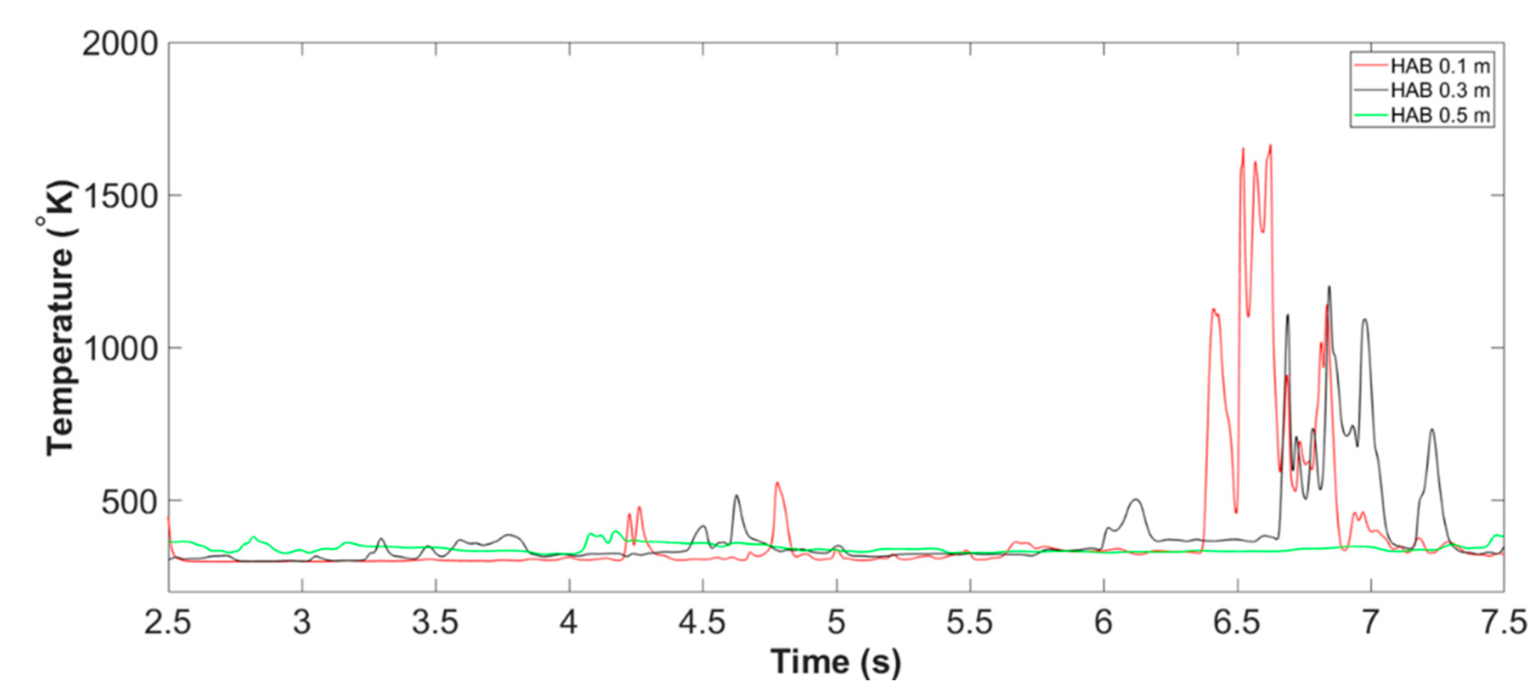
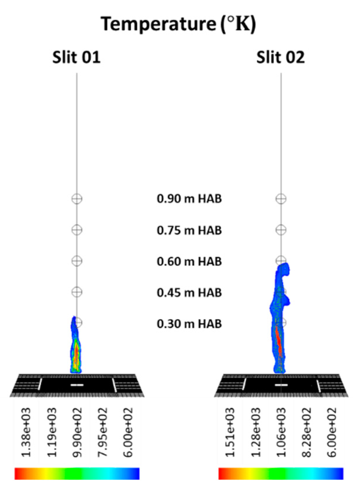
  • The nascent fire whirl formulated in Slit 02 is more intensified and spatially extended compared with baseline case, with the visible height increased by 84.38 % , from 0.32   m to 0.59   m , peak flame temperature increased 9.42 % , from 1380   K to 1510   K and relatively consistent vortex core radius compared with that increase of the monitoring flame height;
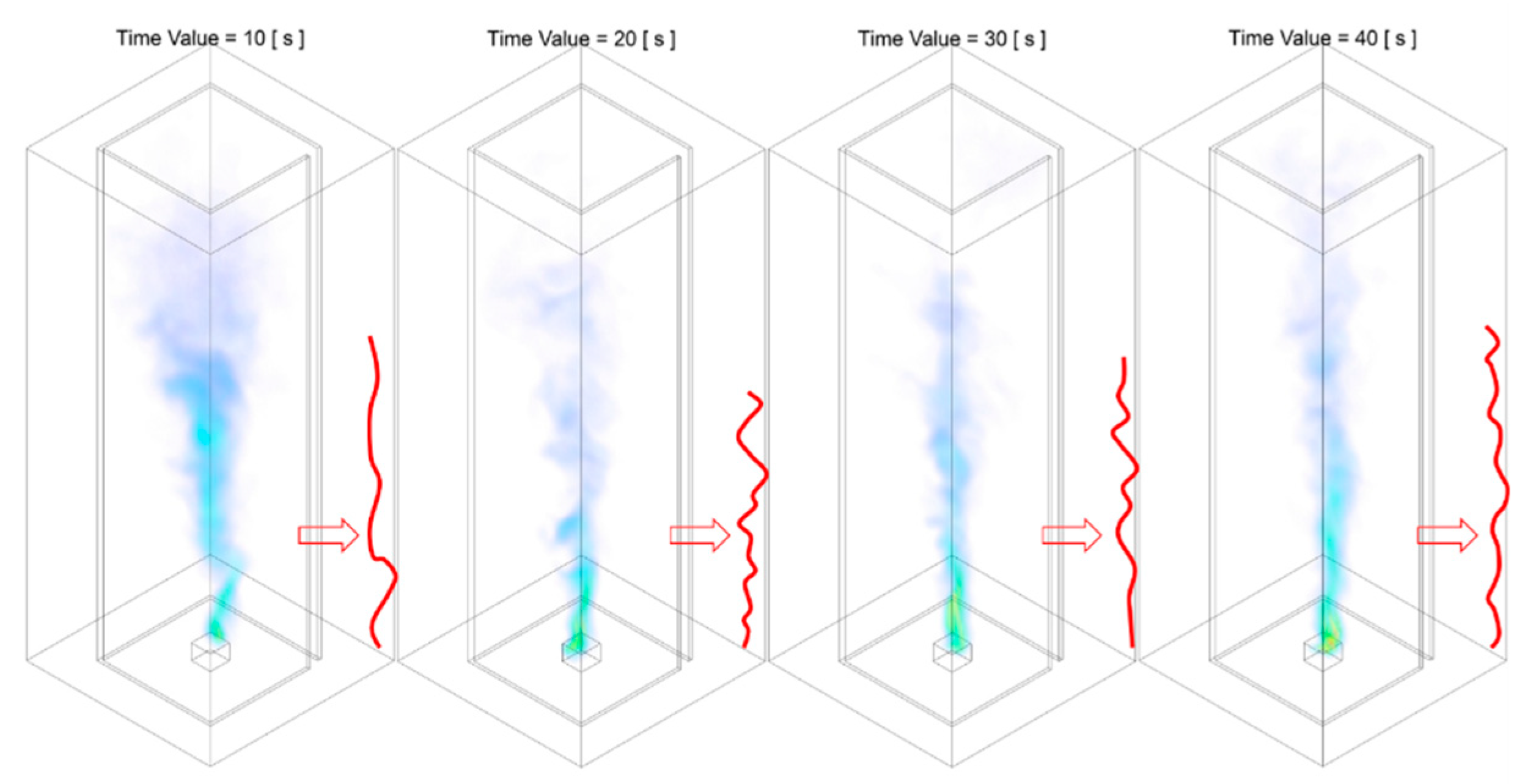
  • Once the nascent fire whirl is formulated, the fire whirl for the baseline model is spinning around the centreline with a relatively small radius of revolution in a semi-steady pattern, for the rest of the simulation duration up to 50 s. On the other hand, the highly centralised fire whirl formulated in the Slit 02 case may gradually diverge via swirling with an increasing radius of revolution. It will eventually achieve an internal balanced semi-stable status that the revolution radius is intensified by the introduction of the additional eddy via the slits and at the same time constrained by the enclosures boundary walls;
  • The revolution obit of the fire whirl could be potentially explained based on the theory of circular motion with constant surface drag force to create a radial boundary layer, acting as the centripetal force that balances the velocity field of the vortex and the radius of revolution. It has been observed in both cases that increased radius of revolution is observed as the fire whirl core structure approaches the slit and hence intensified its velocity field, and vice verse decreased as it departs from the near slit region, to balance the constant burning rate that fixed the surface drag force.
  • The incoming velocity of the slit is observed to be proportional with the distance between the vortex core centre and the slit in the baseline case, which agrees well with the flow dynamic driven by pressure gradient. However, the incoming velocity is observed to decrease as the swirling plume approaches the slit and increase as it departs, which may be attributable to the disturbance of and potential interaction between of the swirling reacting flow and naturally ventilated flow pattern.
In summary, the results collectively compare the complete formation and evolution pathway of the fire whirl under both under symmetrical and asymmetrical entraining scheme. The result demonstrates that the fire whirl formulated in the single asymmetrical configuration is relatively smaller in size, and it swirling with respect to the fuel pan in a relatively smaller radius as the centripetal drag force corrected its obit as it rotates through the enclosed wall regions. Comparatively, the fire whirl generated by symmetrical slits configuration is observed to have higher visible height and relatively more regulated share once it has been formulated. Its revolution orbit gradually evolves as its radius of rotation constantly increased by the intensification of the vortex core velocity field, and eventually reaches a semi-stable status as its move pattern is constrained by the enclosed wall. The result presented in the current work provides a visual of the entire development of the combustion event that aids the understanding of the complexed phenomenon couples with flow dynamics and combustion. It also demonstrates that the proposed numerical framework is feasible to reveal the fundamental information and probe the possible correlation between the geometrical configuration and the development of the combustion behaviour. The information delivered could be beneficial for both research and industrial communities and could be further implemented to enhance in building design, hazard prevention and control as well as evacuation planning.

Author Contributions

Conceptualization, A.C.Y.Y., Q.N.C., S.K. and G.H.Y.; data curation, C.W. and H.L.Y.; formal analysis, C.W., T.B.Y.C., S.C.-P.C. and H.L.Y.; funding acquisition, A.C.Y.Y. and G.H.Y.; methodology, A.C.Y.Y., Q.N.C., S.K. and G.H.Y.; resources, S.K.; supervision, A.C.Y.Y., Q.N.C., S.K. and G.H.Y.; validation, S.C.-P.C.; visualization, C.W.; writing—original draft, C.W.; writing—review and editing, T.B.Y.C. and S.C.-P.C. All authors have read and agreed to the published version of the manuscript.

Funding

This research was funded by the Australian Research Council (ARC Industrial Transformation Training Centre IC170100032), and Wuhan Shuanglian-Xingxin Machinery & Equipment Co. Ltd., China.

Acknowledgments

The authors wish to acknowledge the financial support of Australian Research Council (ARC Industrial Transformation Training Centre IC170100032) and the Australian Government Research Training Program Scholarship. It is also sponsored by Wuhan Shuanglian-Xingxin Machinery and Equipment Co. Ltd., China. The authors deeply appreciate all financial and technical supports.

Conflicts of Interest

The authors declare no conflicts of interest.

References

  1. Tohidi, A.; Gollner, M.J.; Xiao, H. Fire Whirls. Annu. Rev. Fluid Mech. 2018, 50, 187–213. [Google Scholar] [CrossRef] [Green Version]
  2. Wang, P.; Liu, N.; Bai, Y.; Zhang, L.; Satoh, K.; Liu, X. An experimental study on thermal radiation of fire whirl. Int. J. Wildland Fire 2017, 26, 693. [Google Scholar] [CrossRef]
  3. Medwell, P.R.; Chan, Q.N.; Kalt, P.A.M.; Alwahabi, Z.T.; Dally, B.B.; Nathan, G.J. Instantaneous Temperature Imaging of Diffusion Flames Using Two-Line Atomic Fluorescence. Appl. Spectrosc. 2010, 64, 173–176. [Google Scholar] [CrossRef] [PubMed]
  4. Soma, S.; Saito, K. Reconstruction of fire whirls using scale models. Combust. Flame 1991, 86, 269–284. [Google Scholar] [CrossRef]
  5. Zhou, K.; Liu, N.; Yin, P.; Yuan, X.; Jiang, J. Fire Whirl due to Interaction between Line Fire and Cross Wind. Fire Saf. Sci. 2014, 11, 1420–1429. [Google Scholar] [CrossRef]
  6. Byram, G.; Martin, R. The Modeling of Fire Whirlwinds. For. Sci. 1970, 16, 386–399. [Google Scholar]
  7. Lei, J.; Liu, N.; Tu, R. Flame height of turbulent fire whirls: A model study by concept of turbulence suppression. Proc. Combust. Inst. 2017, 36, 3131–3138. [Google Scholar] [CrossRef]
  8. Yuen, A.C.Y.; Yeoh, G.H.; Cheung, S.C.P.; Chan, Q.N.; Chen, T.B.Y.; Yang, W.; Lu, H. Numerical study of the development and angular speed of a small-scale fire whirl. J. Comput. Sci. 2018, 27, 21–34. [Google Scholar] [CrossRef]
  9. Church, C.R.; Snow, J.T.; Dessens, J. Intense Atmospheric Vortices Associated with a 1000 MW Fire. Bull. Am. Meteorol. Soc. 1980, 61, 682–694. [Google Scholar] [CrossRef] [Green Version]
  10. Forthofer, J.M.; Goodrick, S.L. Review of Vortices in Wildland Fire. J. Combust. 2011, 2011, 984363. [Google Scholar] [CrossRef]
  11. Liu, N.; Liu, Q.; Deng, Z.; Kohyu, S.; Zhu, J. Burn-out time data analysis on interaction effects among multiple fires in fire arrays. Proc. Combust. Inst. 2007, 31, 2589–2597. [Google Scholar] [CrossRef]
  12. Emori, R.I.; Saito, K. Model experiment of hazardous forest fire whirl. Fire Technol. 1982, 18, 319–327. [Google Scholar] [CrossRef]
  13. Kuwana, K.; Morishita, S.; Dobashi, R.; Chuah, K.H.; Saito, K. The burning rate’s effect on the flame length of weak fire whirls. Proc. Combust. Inst. 2011, 33, 2425–2432. [Google Scholar] [CrossRef]
  14. Chuah, K.H.; Kuwana, K.; Saito, K.; Williams, F.A. Inclined fire whirls. Proc. Combust. Inst. 2011, 33, 2417–2424. [Google Scholar] [CrossRef]
  15. Lei, J.; Liu, N.; Zhang, L.; Chen, H.; Shu, L.; Chen, P.; Deng, Z.; Zhu, J.; Satoh, K.; De Ris, J.L. Experimental research on combustion dynamics of medium-scale fire whirl. Proc. Combust. Inst. 2011, 33, 2407–2415. [Google Scholar] [CrossRef]
  16. Zhou, K.; Liu, N.; Lozano, J.S.; Shan, Y.; Yao, B.; Satoh, K. Effect of flow circulation on combustion dynamics of fire whirl. Proc. Combust. Inst. 2013, 34, 2617–2624. [Google Scholar] [CrossRef]
  17. Taylor Thomson Whitting 50 Martin Place. Available online: https://www.ttw.com.au/projects/50-martin-place/ (accessed on 29 November 2019).
  18. Lin, B.; Yuen, A.C.Y.; Li, A.; Zhang, Y.; Chen, T.B.Y.; Yu, B.; Lee, E.W.M.; Peng, S.; Yang, W.; Lu, H.-D.; et al. MXene/chitosan nanocoating for flexible polyurethane foam towards remarkable fire hazards reductions. J. Hazard. Mater. 2020, 381, 120952. [Google Scholar] [CrossRef]
  19. Yang, W.-J.; Yuen, A.C.Y.; Li, A.; Lin, B.; Chen, T.B.Y.; Yang, W.; Lu, H.-D.; Yeoh, G.H. Recent progress in bio-based aerogel absorbents for oil/water separation. Cellulose 2019, 26, 6449–6476. [Google Scholar] [CrossRef]
  20. Si, J.-Y.; Tawiah, B.; Sun, W.-L.; Lin, B.; Wang, C.; Yuen, A.C.Y.; Yu, B.; Li, A.; Yang, W.; Lu, H.-D.; et al. Functionalization of MXene Nanosheets for Polystyrene towards High Thermal Stability and Flame Retardant Properties. Polymers 2019, 11, 976. [Google Scholar] [CrossRef] [Green Version]
  21. Yu, B.; Tawiah, B.; Wang, L.-Q.; Yuen, A.C.Y.; Zhang, Z.-C.; Shen, L.-L.; Lin, B.; Fei, B.; Yang, W.; Li, A.; et al. Interface decoration of exfoliated MXene ultra-thin nanosheets for fire and smoke suppressions of thermoplastic polyurethane elastomer. J. Hazard Mater. 2019, 374, 110–119. [Google Scholar] [CrossRef]
  22. Yuen, A.C.Y.; Chen, T.B.Y.; Wang, C.; Wei, W.; Kabir, I.; Vargas, J.B.; Chan, Q.N.; Kook, S.; Yeoh, G.H. Utilising genetic algorithm to optimise pyrolysis kinetics for fire modelling and characterisation of chitosan/graphene oxide polyurethane composites. Compos. Part B Eng. 2020, 182, 107619. [Google Scholar] [CrossRef]
  23. Chen, T.; Yuen, A.; Yeoh, G.; Yang, W.; Chan, Q. Fire Risk Assessment of Combustible Exterior Cladding Using a Collective Numerical Database. Fire 2019, 2, 11. [Google Scholar] [CrossRef] [Green Version]
  24. Li, A.; Yuen, A.C.Y.; Chen, T.B.Y.; Wang, C.; Liu, H.; Cao, R.; Yang, W.; Yeoh, G.H.; Timchenko, V. Timchenko Computational Study of Wet Steam Flow to Optimize Steam Ejector Efficiency for Potential Fire Suppression Application. Appl. Sci. 2019, 9, 1486. [Google Scholar] [CrossRef] [Green Version]
  25. Yuen, A.C.Y.; Yeoh, G.H.; Alexander, B.; Cook, M. Fire scene investigation of an arson fire incident using computational fluid dynamics based fire simulation. Build. Simul. 2014, 7, 477–487. [Google Scholar] [CrossRef]
  26. Yuen, A.C.Y.; Yeoh, G.H.; Alexander, R.; Cook, M. Fire scene reconstruction of a furnished compartment room in a house fire. Case Stud. Fire Saf. 2014, 1, 29–35. [Google Scholar] [CrossRef] [Green Version]
  27. Dobashi, R.; Okura, T.; Nagaoka, R.; Hayashi, Y.; Mogi, T. Experimental Study on Flame Height and Radiant Heat of Fire Whirls. Fire Technol. 2016, 52, 1069–1080. [Google Scholar] [CrossRef]
  28. Hartl, K.A.; Smits, A.J. Scaling of a small scale burner fire whirl. Combust. Flame 2016, 163, 202–208. [Google Scholar] [CrossRef]
  29. Wang, P.; Liu, N.; Hartl, K.; Smits, A. Measurement of the Flow Field of Fire Whirl. Fire Technol. 2016, 52, 263–272. [Google Scholar] [CrossRef]
  30. Xiao, H.; Gollner, M.J.; Oran, E.S. From fire whirls to blue whirls and combustion with reduced pollution. Proc. Natl. Acad. Sci. USA 2016, 113, 9457–9462. [Google Scholar] [CrossRef] [Green Version]
  31. Muraszew, A.; Fedele, J.B.; Kuby, W.C. The fire whirl phenomenon. Combust. Flame 1979, 34, 29–45. [Google Scholar] [CrossRef]
  32. Chuah, K.H.; Kushida, G. The prediction of flame heights and flame shapes of small fire whirls. Proc. Combust. Inst. 2007, 31, 2599–2606. [Google Scholar] [CrossRef]
  33. Parente, R.M.; Pereira, J.M.C.; Pereira, J.C.F. On the influence of circulation on fire whirl height. Fire Saf. J. 2019, 106, 146–154. [Google Scholar] [CrossRef]
  34. Wang, C.; Chan, Q.N.; Kook, S.; Hawkes, E.R.; Medwell, P.R.; Lee, J. Development of an in-flame thermophoretic soot sampling device. In Proceedings of the Australian Combustion Symposium, Melbourne, Australia, 7–9 December 2015; pp. 360–363. [Google Scholar]
  35. Wang, C.; Chan, Q.N.; Kook, S.; Hawkes, E.R.; Medwell, P.R.; Lee, J. External Irradiation Effect on the Evolution of In-flame Soot Species. In Proceedings of the Australian Combustion Symposium, Melbourne, Australia, 7–9 December 2015; pp. 364–367. [Google Scholar]
  36. Lei, J.; Liu, N.; Satoh, K. Buoyant pool fires under imposed circulations before the formation of fire whirls. Proc. Combust. Inst. 2015, 35, 2503–2510. [Google Scholar] [CrossRef]
  37. Lei, J.; Liu, N.; Zhang, L.; Satoh, K. Temperature, velocity and air entrainment of fire whirl plume: A comprehensive experimental investigation. Combust. Flame 2015, 162, 745–758. [Google Scholar] [CrossRef]
  38. Sikanen, T.; Hostikka, S. Modeling and simulation of liquid pool fires with in-depth radiation absorption and heat transfer. Fire Saf. J. 2016, 80, 95–109. [Google Scholar] [CrossRef]
  39. Yao, W.; Yin, J.; Hu, X.; Wang, J.; Zhang, H. Numerical modeling of liquid n-heptane pool fires based on heat feedback equilibrium. Procedia Eng. 2013, 62, 377–388. [Google Scholar] [CrossRef] [Green Version]
  40. Wang, C.; Chan, Q.N.; Zhang, R.; Kook, S.; Hawkes, E.R.; Yeoh, G.H.; Medwell, P.R. Automated determination of size and morphology information from soot transmission electron microscope (TEM)-generated images. J. Nanopart. Res. 2016, 18, 127. [Google Scholar] [CrossRef]
  41. Wang, C.; Chan, Q.N.; Kook, S.; Hawkes, E.R.; Lee, J.; Medwell, P.R. External irradiation effect on the growth and evolution of in-flame soot species. Carbon N. Y. 2016, 102, 161–171. [Google Scholar] [CrossRef] [Green Version]
  42. Yuen, A.C.Y.; Yeoh, G.H.; Timchenko, V.; Cheung, S.C.P.; Chan, Q.N.; Chen, T. On the influences of key modelling constants of large eddy simulations for large-scale compartment fires predictions. Int. J. Comut. Fluid Dyn. 2017, 31, 324–337. [Google Scholar] [CrossRef]
  43. Yuen, A.C.Y.; Yeoh, G.H.; Timchenko, V.; Chen, T.B.Y.; Chan, Q.N.; Wang, C.; Li, D.D. Comparison of detailed soot formation models for sooty and non-sooty flames in an under-ventilated ISO room. Int. J. Heat Mass Transf. 2017, 115, 717–729. [Google Scholar] [CrossRef]
  44. Tree, D.R.; Svensson, K.I. Soot processes in compression ignition engines. Prog. Energy Combust. Sci. 2007, 33, 272–309. [Google Scholar] [CrossRef]
  45. Wang, H. Formation of nascent soot and other condensed-phase materials in flames. Proc. Combust. Inst. 2011, 33, 41–67. [Google Scholar] [CrossRef]
  46. Jones, W.P.; Whitelaw, J.H. Calculation methods for reacting turbulent flows: A review. Combust. Flame 1982, 48, 1–26. [Google Scholar] [CrossRef]
  47. Liu, H.; Wang, C.; De Cachinho Cordeiro, I.M.; Yuen, A.C.Y.; Chen, Q.; Chan, Q.N.; Kook, S.; Yeoh, G.H. Critical assessment on operating water droplet sizes for fire sprinkler and water mist systems. J. Build. Eng. 2020, 28, 100999. [Google Scholar] [CrossRef]
  48. Chow, W.; Han, S.S. Experimental Data on Scale Modeling Studies on Internal Fire Whirls. Int. J. Eng. Perform. Based Fire Codes 2011, 10, 63–74. [Google Scholar]
  49. Wang, C.; Chun, A.; Yuen, Y.; Chan, Q.N.; Bo, T.; Chen, Y.; Chen, Q.; Cao, R.; Yip, H.L.; Kook, S.; et al. Influence of Eddy-Generation Mechanism on the Characteristic of On-Source Fire Whirl. Appl. Sci. 2019, 9, 3989. [Google Scholar] [CrossRef] [Green Version]
  50. Chen, T.B.Y.; Yuen, A.C.Y.; Wang, C.; Yeoh, G.H.; Timchenko, V.; Cheung, S.C.P.; Chan, Q.N.; Yang, W. Predicting the fire spread rate of a sloped pine needle board utilizing pyrolysis modelling with detailed gas-phase combustion. Int. J. Heat Mass Transf. 2018, 125, 310–322. [Google Scholar] [CrossRef]
  51. Yuen, A.; Chen, T.; Yang, W.; Wang, C.; Li, A.; Yeoh, G.; Chan, Q.; Chan, M. Natural Ventilated Smoke Control Simulation Case Study Using Different Settings of Smoke Vents and Curtains in a Large Atrium. Fire 2019, 2, 7. [Google Scholar] [CrossRef] [Green Version]
  52. Yuen, A.C.Y.; Yeoh, G.H.; Timchenko, V.; Cheung, S.C.P.; Chen, T. Study of three LES subgrid-scale turbulence models for predictions of heat and mass transfer in large-scale compartment fires. Numer. Heat Transf. Part A Appl. 2016, 69, 1223–1241. [Google Scholar] [CrossRef]
  53. Yuen, A.C.Y. On the Prediction of Combustion Products and Soot Particles in Compartment Fires. Ph.D. Thesis, University of New South Wales, Sydney, Australia, 2014. [Google Scholar]
  54. Wang, C. External Irradiation Effect on the Evolution of In-flame Soot Species. M.E. Thesis, University of New South Wales, Sydney, Australia, 2016. [Google Scholar]
  55. Yuen, A.C.Y.; Yeoh, G.H.; Timchenko, V.; Barber, T. LES and multi-step chemical reaction in compartment fires. Numer. Heat Transf. Part A Appl. 2015, 68, 711–736. [Google Scholar] [CrossRef]
  56. Kee, R.J.; Rupley, F.M.; Miller, J.A.; Coltrin, M.E.; Grcar, J.F.; Meeks, E.; Moffat, H.K.; Lutz, A.E.; Dixon-Lewis, G.; Smooke, M.D.; et al. CHEMKIN collection Release 3.6. In CHEMKIN Collection Release 3.6; Reaction Design. Inc.: San Diego, CA, USA, 2000. [Google Scholar]
  57. Yuen, A.C.Y.; Yeoh, G.H.; Timchenko, V.; Cheung, S.C.P.; Barber, T.J. Importance of detailed chemical kinetics on combustion and soot modelling of ventilated and under-ventilated fires in compartment. Int. J. Heat Mass Transf. 2016, 96, 171–188. [Google Scholar] [CrossRef]
  58. Yuen, A.C.Y.; Chen, T.B.Y.; Yeoh, G.H.; Yang, W.; Cheung, S.C.P.; Cook, M.; Yu, B.; Chan, Q.N.; Yip, H.L. Establishing pyrolysis kinetics for the modelling of the flammability and burning characteristics of solid combustible materials. J. Fire Sci. 2018, 36, 494–517. [Google Scholar] [CrossRef] [Green Version]
  59. Chen, T.B.Y.; Yuen, A.C.Y.; Yeoh, G.H.; Timchenko, V.; Cheung, S.C.P.; Chan, Q.N.; Yang, W.; Lu, H. Numerical study of fire spread using the level-set method with large eddy simulation incorporating detailed chemical kinetics gas-phase combustion model. J. Comput. Sci. 2018, 24, 8–23. [Google Scholar] [CrossRef]
  60. Wang, C.; Yuen, A.C.Y.; Chan, Q.N.; Chen, T.B.Y.; Yang, W.; Cheung, S.C.-P.; Yeoh, G.H. Sensitivity Analysis of Key Parameters for Population Balance Based Soot Model for Low-Speed Diffusion Flames. Energies 2019, 12, 910. [Google Scholar] [CrossRef] [Green Version]
  61. Mueller, M.E.; Chan, Q.N.; Qamar, N.H.; Dally, B.B.; Pitsch, H.; Alwahabi, Z.T.; Nathan, G.J. Experimental and computational study of soot evolution in a turbulent nonpremixed bluff body ethylene flame. Combust. Flame 2013, 160, 1298–1309. [Google Scholar] [CrossRef]
  62. Wang, C.; Yuen, A.C.Y.; Chan, Q.N.; Chen, T.B.Y.; Yang, W.; Cheung, S.C.P.; Yeoh, G.H. Characterisation of soot particle size distribution through population balance approach and soot diagnostic techniques for a buoyant non-premixed flame. J. Energy Inst. 2019, 93, 112–128. [Google Scholar] [CrossRef]
Figure 1. Example of the internal structure of a high-rise building features atrium and spiral staircase [17].
Applsci 10 00318 g001
Figure 2. Geometric features of the computational domain.
Applsci 10 00318 g002
Figure 3. Centerline temperature of Slit 01 case at all monitoring HABs, from 00.00 s to 50.00 s, consist of three main stages of the development and evolution of fire whirl, namely Stage A: flame development, Stage B: fire whirl development and Stage C: fire whirl formation and evolution.
Applsci 10 00318 g003
Figure 4. Centerline temperature of Slit 02 case at all monitoring height above burners (HABs), from 00.00 s to 50.00 s, consist of three main stages of the development and evolution of fire whirl, namely Stage A: flame development, Stage B: fire whirl development and Stage C: fire whirl formation and evolution.
Applsci 10 00318 g004
Figure 5. Centerline temperature of Slit 01 case at all monitoring HABs, from 00.00 s to 05.00 s (example of Stage A: flame development).
Applsci 10 00318 g005
Figure 6. Temperature iso-surface at representative instant of time during Stage A of the combustion process: from the ignition to the fully developed buoyant diffusion flame, of Slit 01 case.
Applsci 10 00318 g006
Figure 7. Temperature iso-surface at representative instant of time during Stage A of the combustion process: from fully developed flame to flame tilting and flickering in a random manner, of the Slit 01 case. The region highlighted in grey indicates that flame starts to flicker, whereas the region further upstream persists a relatively straight profile.
Applsci 10 00318 g007
Figure 8. Centerline temperature of Slit 02 case at all monitoring HABs, from 00.00 s to 05.00 s (example of Stage A: flame development).
Applsci 10 00318 g008
Figure 9. Temperature iso-surface at representative instant of time during Stage A of the combustion process: from the ignition to the fully developed buoyant diffusion flame, of Slit 02 case.
Applsci 10 00318 g009
Figure 10. Temperature iso-surface at representative instant of time during Stage A of the combustion process: from fully developed flame to flame tilting and flickering in a random manner, of Slit 02 case. The region highlighted in grey indicates that flame starts to flicker, whereas the region further upstream persists a relatively straight profile.
Applsci 10 00318 g010
Figure 11. Centerline temperature of Slit 01 case at all monitoring HABs, from 02.50 s to 07.50 s (example of Stage B: fire whirl development and formation).
Applsci 10 00318 g011
Figure 12. Temperature iso-surface at representative instant of time during Stage B of the combustion process: from randomly flickering flame to the emerging of rotating reacting flow, of the Slit 01 case. The red solid line approximately illustrates the shape of the flame core region structure.
Applsci 10 00318 g012
Figure 13. Temperature iso-surface at representative instant of time during Stage B of the combustion process: flame restoring from emerging of the swirling reacting flow back to that flickering randomly, of the Slit 01 case.
Applsci 10 00318 g013
Figure 14. Temperature iso-surface at representative instant of time during Stage B of the combustion process: the formation of nascent fire whirl, of the Slit 01 case. The red solid line approximately illustrates the shape of the flame core region structure.
Applsci 10 00318 g014
Figure 15. Centerline temperature of Slit 02 case at all monitoring HABs, from 02.50 s to 06.00 s (example of Stage B: fire whirl development and formation).
Applsci 10 00318 g015
Figure 16. Temperature iso-surface at representative instant of time during Stage B of the combustion process: from randomly flickering flame to the emerging of rotating reacting flow, of the Slit 02 case. The red solid line approximately illustrates the shape of the flame core region structure.
Applsci 10 00318 g016
Figure 17. Temperature iso-surface at representative instant of time during Stage B of the combustion process: flame restoring from emerging of the swirling reacting flow back to that flickering randomly, of Slit 02 case.
Applsci 10 00318 g017
Figure 18. Temperature iso-surface at representative instant of time during Stage B of the combustion process: the formation of nascent fire whirl, of Slit 02 case. The red solid line approximately illustrates the shape of the flame core region structure.
Applsci 10 00318 g018
Figure 19. The visible flame height of the fire whirl formulated by the Slit 01 case and the Slit 02 case.
Applsci 10 00318 g019
Figure 20. Centerline temperature of the Slit 01 case at all monitoring HABs, from 10.00 s to 20.00 s (example of Stage C: fire whirl evolution).
Applsci 10 00318 g020
Figure 21. Temperature iso-surface at representative instant of time during Stage C of the combustion process: the evolution of fire whirl, of the Slit 01 case. The red solid line approximately illustrates the shape of the flame core region structure.
Applsci 10 00318 g021
Figure 22. Centerline temperature of the Slit 02 case at all monitoring HABs, from 06.00 s to 12.00 s (example of Stage C1: fire whirl evolution).
Applsci 10 00318 g022
Figure 23. Temperature iso-surface at representative instant of time during Stage C1 of the combustion process: the first phase of the evolution of fire whirl, of the Slit 02 case. The red solid line approximately illustrates the shape of the flame core region structure.
Applsci 10 00318 g023
Figure 24. Centerline temperature of the Slit 02 case at all monitoring HABs, from 12.00 s to 20.00 s (example of Stage C2: fire whirl evolution).
Applsci 10 00318 g024
Figure 25. Temperature iso-surface at representative instant of time during Stage C2 of the combustion process: the second phase of the evolution of fire whirl, of the Slit 02 case. The red solid line approximately illustrates the shape of the flame core region structure.
Applsci 10 00318 g025
Figure 26. Centerline temperature of the Slit 02 case at all monitoring HABs, from 20.00 s to 30.00 s (example of Stage C3: fire whirl evolution).
Applsci 10 00318 g026
Figure 27. Temperature iso-surface at representative instant of time during Stage C3 of the combustion process: the final phase of the evolution of fire whirl, of the Slit 02 case. The red solid line approximately illustrates the shape of the flame core region structure.
Applsci 10 00318 g027
Figure 28. Pressure contour of the domain at 0.1 m HAB, at five timesteps of the Slit 01 case selected based on representative time instants associated with Slit 01 (anti-clockwise from top-right with increase in time). The contours indicate the fire whirl core location and collectively illustrate a full circle of orbital revolution of the whirling reacting flow with respect to fuel source.
Applsci 10 00318 g028
Figure 29. Vector field plot of the domain at 0.1 m HAB, at five timesteps of the Slit 01 case selected based on representative time instants associated with Slit 01 (anti-clockwise from top-right with increase in time). The plots indicate the fire whirl core location and collectively illustrate a full circle of orbital revolution of the whirling reacting flow with respect to fuel source.
Applsci 10 00318 g029
Figure 30. Orbit of fire whirl core centre of the Slit 01 case, indicating the fire whirl’s revolution around the fuel source, starring from Applsci 10 00318 i002, and end with Applsci 10 00318 i003 (with approximately one complete circle of revolution in anti-clockwise direction). The blue arrow indicates the tendency of changing of slit incoming velocity.
Applsci 10 00318 g030
Figure 31. Plot of incoming velocity of the Slit 01 for Slit 01 case, with the marks indicating the representative time instant corresponding to Figure 30.
Applsci 10 00318 g031
Figure 32. Pressure contour of the domain at 0.1 m HAB, at five timesteps of Slit 02 case selected based on representative time instants associated with Slit 1 (anti-clockwise from top-right with increase in time). The contours indicate the fire whirl core location and collectively illustrate a full circle of orbital revolution of the whirling reacting flow with respect to fuel source.
Applsci 10 00318 g032
Figure 33. Vector field plot of the domain at 0.1 m HAB, at five timesteps of Slit 02 case selected based on representative time instants associated with Slit 1 (anti-clockwise from top-right with increase in time). The plots indicate the fire whirl core location and collectively illustrate a full circle of orbital revolution of the whirling reacting flow with respect to fuel source.
Applsci 10 00318 g033
Figure 34. Pressure contour of the domain at 0.1 m HAB, at five timesteps of Slit 02 case selected based on representative time instants associated with Slit 2 (anti-clockwise from top-right with increase in time). The contours indicate the fire whirl core location and collectively illustrate a full circle of orbital revolution of the whirling reacting flow with respect to fuel source.
Applsci 10 00318 g034
Figure 35. Vector field plot of the domain at 0.1 m HAB, at five timesteps of Slit 02 case selected based on representative time instants associated with Slit 2 (anti-clockwise from top-right with increase in time). The plots indicate the fire whirl core location and collectively illustrate a full circle of orbital revolution of the whirling reacting flow with respect to fuel source.
Applsci 10 00318 g035
Figure 36. Orbit of fire whirl core centre of the Slit 02 case, indicating the fire whirl’s revolution around the fuel source, with time instant associated with Slit 1 and Slit 2 denoted as Applsci 10 00318 i001 and Applsci 10 00318 i008 respectively. The blue arrow indicates the tendency of changing of slit incoming velocity.
Applsci 10 00318 g036
Figure 37. Plot of incoming velocity of the Slit 01 and Slit 02 cases, with the marks indicating the representative time instant corresponding to Figure 36.
Applsci 10 00318 g037
Table 1. General transport equation variable, diffusion and source terms.
Φ Γ Φ S ( Φ ) ˜
1 0 0
U ˜ j μ + μ T p ¯ x j + x j ( μ U ˜ i x j 2 3 μ U ˜ k x k ) τ i j x j + ( ρ ¯ ρ r e f ) g j + S ( U ) ˜
c p T ˜ μ P r + μ T P r T ω ˜ T + S ( r a d ) ˜
Φ μ S c + μ T S c T S ( Φ ) ˜

