1. Introduction
Traffic congestion is a persistently growing trend and has a great economic impact in terms of the time consumption of commuters and the fuel of vehicles [
1]. To solve the traffic congestion problem, numerous studies have been conducted with a wide range of perspectives. Over the last few decades, the research on traffic management in the form of reducing traffic congestion by effectively distributing traffic on the roads has been mainly conducted [
2,
3,
4]. In terms of improving the precision of traffic management techniques, developing more realistic traffic models and advanced traffic prediction tools has also been one of the key topics [
5,
6,
7,
8,
9].
The introduction of wireless communication technology has allowed much wider and more sophisticated approaches in traffic management by means of providing timely information to drivers, vehicles, and systems. Wireless Sensor Networks (WSNs), which are capable of monitoring real-time traffic using low-cost communication devices such as ZigBee and Bluetooth devices, have gain increasing attention [
10,
11,
12]. Also, there has been significant research on Cooperative Intelligent Transportation Systems (C-ITS) where each component on the road bidirectionally communicates to each other taking advantage of broadband wireless communication systems [
13,
14,
15], such as Dedicated Short Range Communication (DSRC) [
16] and 3rd Generation Partnership Project (3GPP) Long Term Evolution (LTE) [
17].
Lately, platooning, which combines autonomous driving and advanced communication techniques, has been spotlighted as a breakthrough technology and intensively studied [
18,
19,
20,
21]. In platooning, autonomous vehicles share their driving information among neighboring vehicles, and organize themselves into a set called a platoon. Since platooning can increase the road capacity by reducing the inter-vehicle distance, it is considered one of the most promising solutions for future congestion management.
To efficiently manage autonomous platoon without compromising safety aspect, cooperative awareness among platooning vehicles needs to be guaranteed. One of the most common ways to achieve the cooperative awareness is beaconing where all vehicles periodically broadcast their general information using V2V wireless communication. A beaconing message may include vehicles’ positioning information and driving information such as speed, accelerating/braking force and steering, peripheral information measured by sensors attached to vehicles. SAE J2735 [
22] defines the format of the Basic Safety Message (BSM) as the application of beaconing message and is widely applied for numerous vehicular networks.
As a bearer of BSM messages, DSRC leveraging the IEEE 802.11p standard [
23] has been mainly considered in the early stage of vehicular networks. The IEEE 802.11p standard is designed to operate in 5.850–5.925 GHz band and developed based on the IEEE 802.11a Wireless LAN PHY/MAC specification. There are couple of advantages using IEEE 802.11p standard in vehicular communications: (1) a centralized controlling entity is not required because each vehicle is allowed to access the medium in a distributed manner, (2) easy and low-cost deployment is possible since the network operates in unlicensed band, and also it does not require higher layer infrastructure.
Several DSRC-related pieces of research have been conducted to evaluate the performance of DSRC. Ma et al. [
24] introduced the basic parameter space for one-dimensional IEEE 802.11p networks derived with the IEEE 802.11 Distributed Coordination Function (DCF) model. In [
25], an analytical model for safety message broadcasting was proposed. The model took vehicles’ high mobility, hidden terminal problems, the transmission collisions from neighboring vehicles, and the channel fading in DSRC networks into account. In [
26], an analytical model for delivering safety messages using prioritized Access Classes (ACs) was proposed to analyze the performance of EDCA considering virtual collisions, Arbitration Inter-frame Spacing (AIFS) differentiation, the retry limit and the difference among frame blocking probability, frame collision probability and channel busy probability into considerations. In [
27], authors proposed an analytical model for DSRC networks where broadcast safety message and unicast non-safety message share the medium with different priorities.
According to the past research, IEEE 802.11p can provide a decent V2V communication quality in moderate network traffic condition. As network congestion increases; however, the delay performance of channel access degrades severely because the Carrier-Sense Multiple Access with Collision Avoidance (CSMA/CA) incurs an excessive medium contention overhead in heavy traffic situation. Envisioning the future platooning environment, platooning application will require vehicles to exchange more various types of information with increased size to achieve more precise control of platoon driving. Furthermore, the adoption of platooning will possibly increase vehicle density which means that several contending nodes for channel access will also increase in the network. This rationale raises concerns that DSRC may not properly meet the requirements of future platooning.
Meanwhile, IEEE Standard Association (SA) has commenced to develop the successor of IEEE 802.11p recently. As the result of a year of studies on the Next Generation Vehicle (NGV) Vehicle-to-Everything (V2X) Wireless Local Area Network (WLAN), the IEEE 802.11bd Task Group (TG) was formed in January 2019. The main objective of IEEE 802.11bd is to improve throughput, transmission range, and positioning performance [
28]. IEEE 802.11bd not only defines the PHY layer but also the MAC layer including congestion control. As IEEE 802.11p used to embrace many features defined in IEEE 802.11a, IEEE 802.11bd is considering adopting some advanced features from the latest main stream WLAN standard, IEEE 802.11ax [
29].
The IEEE 802.11ax standard has been developed since 2014. The main objective of IEEE 802.11ax is to achieve high efficiency in dense network environment [
30]. In order to solve the longstanding CSMA congestion problem, the IEEE 802.11ax standard has adopted a new channel access scheme, namely Triggered Uplink Access (TUA), which takes advantages of scheduling-based channel access scheme in contrast to the conventional CSMA/CA scheme. In [
31], an analytic model to evaluate the channel use of TUA was proposed. Yang et al. proposed a Markov chain analysis of TUA Uplink Orthogonal Frequency Division Multiple Access (OFDMA) Random Access (UORA) in saturated traffic condition [
32]. In [
33], a V2I channel access scheme using TUA was proposed.
In this paper, we propose a novel channel access scheme for V2V BSM dissemination, called Distributed Triggered Access (DTA). In the proposed scheme, each vehicle that accesses the channel using EDCA to transmit a buffered BSM may solicit simultaneous transmission of nearby vehicles. Leveraging the new PHY layer numerology of the IEEE 802.11ax and the synchronization and instant scheduling features of TUA, the solicited vehicles can perform OFDM) transmission immediately. TUA was primarily proposed to be used in a Basic Service Set (BSS) environment, where a centralized Access Point (AP) device has better understanding on the associated devices and traffic situation so that it can schedule a TUA transmission properly. Since the characteristic of BSM traffic is easy to predict and vehicles are supposed to know the presence of nearby vehicles, in the proposed scheme, TUA is used in distributed manner. To the best of our knowledge, our work is the first attempt to apply TUA to distributed V2V networks and to provide an analytic model of TUA scheme including unsaturated traffic condition. In addition, we also apply the MU-RTS feature of IEEE 802.11ax to deal with the lengthened airtime caused by OFDMA transmission.
The proposed scheme is aiming to solve the following challenges in BSM dissemination scenario: (1) Preventing severe throughput degradation caused by medium access congestion in saturated traffic condition, (2) Decreasing the effect of hidden node problem in high vehicle density, (3) Increasing the successful packet delivery rate in ‘ACK-less’ broadcast situation.
The simulation results corroborate that DTA effectively deals with the aforementioned problems with enhanced BSM dissemination rate, reduced packet loss rate even under very high vehicle density and traffic conditions.
The rest of this paper is organized as follows. In
Section 2, the proposed DTA scheme is described in detail including the background technologies. In
Section 3, mathematical analysis is proposed using the Markov chain analysis and the M/G/1 queuing theory. Simulation results of the proposed scheme are presented in
Section 4. Finally,
Section 5 concludes the paper.
2. Proposed Scheme
In the proposed Distributed Triggered Access (DTA) scheme, vehicular stations (VSTAs) leverage the Triggered Uplink Access (TUA) scheme in the IEEE 802.11ax standard [
29] in order to trigger simultaneous broadcast packet transmission from nearby multiple VSTAs under distributed V2V communication environment.
According to the IEEE 802.11ax standard, when an Access Point (AP) station obtains a transmission opportunity (TXOP) through channel access, it may transmit a Trigger Frame (TF) to initiate a TUA OFDMA transmission sequence. In TUA, since AP is assumed to have knowledge about stations’ (STAs) buffer status through buffer status report procedure, it solicits specific STAs by listing the STAs’ addresses in the TF. The proposed DTA scheme is carefully designed to work under distributed vehicular communication environments. In order to minimize the changes of the standard, DTA is designed on top of TUA. In order to explain the proposed scheme, the overview of TUA is presented in the following.
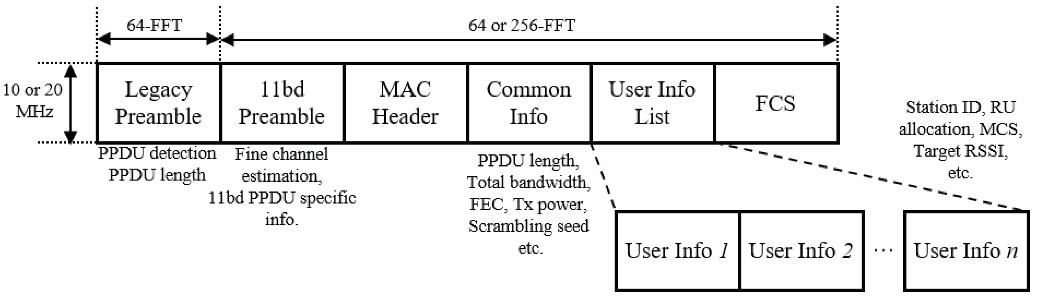
In TUA, the main purpose of TF is to share time synchronization information among scheduled stations as well as scheduling information for each scheduled station. The lack of resource reservation and periodic scheduling procedure makes WLAN difficult to implement uplink multi-user simultaneous transmission. With increased processing capability of station, IEEE 802.11ax implements uplink simultaneous transmission in a manner of immediate responding to the scheduling of triggering station within one TXOP, instead of resource reservation. The remaining challenges to enable the simultaneous uplink transmission as an immediate responding to the scheduling are: (1) making the uplink frame detectable, and (2) the synchronization of the uplink transmission timing. In order to do so, TF contains all necessary physical layer parameters so that all scheduled stations can construct an identical preamble. The Trigger Based (TB) PPDU is transmitted immediately Short Inter-frame Spacing (SIFS) after the reception of the preceding TF, and the triggered STAs calculate the transmission duration using the Modulation and Coding Scheme (MCS) and the PHY layer Service Data Unit (PSDU) length information contained in the TF. The format of TF is depicted in
Figure 1.
The Common Info field contains general information which can be shared by all triggered stations such as the length and the total occupying bandwidth of the triggered PHY layer Protocol Data Unit (PPDU), the properties of the channel coding scheme and the transmit power of the triggering station. The User Info List field may contain multiple User Info fields as many as the number of scheduling Resource Units (RU). Each User Info field indicates the identification of the target triggered station and the scheduled RU as well as user-specific transmission parameters such as MCS, Forward Error Correction (FEC) coding type etc.
If a station receives a TF with valid scheduling information, the station responds with a data packet using the TB PPDU format. Upon the transmission of a TB PPDU, the station needs to construct the first part of the preamble as instructed in the Common Info field of the preceding TF. The first part of the preamble follows the legacy format of IEEE 802.11 PPDU preamble format and occupies the whole 10 MHz channel bandwidth using the conventional 64-FFT OFDM symbols for backward compatibility. Since all scheduled stations transmit an identical preamble signal at the same time, the recipient can detect the start of the PPDU and obtain the length information of the PPDU. For the latter part of the PPDU, each scheduled station transmits individual data packet using the allocated resource with novel 256-FFT OFDM numerology. In this case, all triggered stations need to align the duration of the transmitting PPDU to maintain the synchronization of the transmission sequence.
In the proposed scheme, we assume that the PPDU structure of TB PPDU and the PPDU for TF transmission for IEEE 802.11bd VSTAs follow the format of HE TB and HE SU PPDU defined in the IEEE 802.11ax standard, except that the subcarrier spacing is halved with increased OFDM symbol duration. Following the assumption, a triggering station can schedule up to 9 stations per single 10MHz bandwidth using the smallest RU size with 26 OFDM tones. In this paper, multi-channel transmission in [
34] is not considered. The general format of the proposed TB PPDU is depicted in
Figure 2.
In IEEE 802.11ax, TUA is also applied for a wide-range transmission protection scheme, called MU-RTS. In WLAN, in order to prevent collision, the transmitter and the receiver can perform RTS/CTS (Clear-To-Send) procedure, so that the nearby stations can set a Network Allocation Vector (NAV) and suspend any transmission until the time indicated in the NAV. However, if a transmission is performed by multiple transmitters simultaneously or a transmission is destined to multiple receivers, the protection that covers all communication range cannot be done unless all corresponding transmitters and receivers exchange RTS/CTS one by one sequentially. Thanks to the synchronization feature of TF, a triggering station can solicit simultaneous CTS transmission by transmitting an MU-RTS frame which is a variant of TF. Following the information included in the MU-RTS frame, such as the transmitting bandwidth, the scrambling seed and NAV information, all solicited stations can transmit an identical CTS frame simultaneously. Since the CTS frame follows the legacy OFDM PPDU format, all other stations within the range of simultaneous CTS frame can set a NAV properly. If a transmitted MU-RTS frame had collided with other frame, the transmitter may not receive any CTS frames from nearby stations. In this case, the transmitter release the TXOP and re-initiate an EDCA backoff procedure.
The proposed distributed multi-vehicle channel access scheme, DTA, fully exploits all the beneficial features of TUA and MU-RTS. Although the proposed scheme can accommodate all kinds of Outside the Context of Basic Service Set (OCB) traffics, for the sake of simplicity, Basic Safety Message (BSM), which is a broadcast traffic and the most common traffic in V2X communications, is used in the description of the proposed scheme.
In the proposed scheme, two types of channel access methods coexist. One is conventional EDCA, the other is Triggered Access (TA) in which VSTA accesses the channel triggered by another VSTA, independent from its own EDCA backoff procedure. Whenever a VSTA acquires a TXOP after finishing its backoff procedure, it plays a role of triggering VSTA. In order to solicit multiple VSTAs’ simultaneous BSM transmission, the triggering VSTA transmits a TF, which contains the scheduling information for multiple VSTAs, at the beginning of the TXOP.
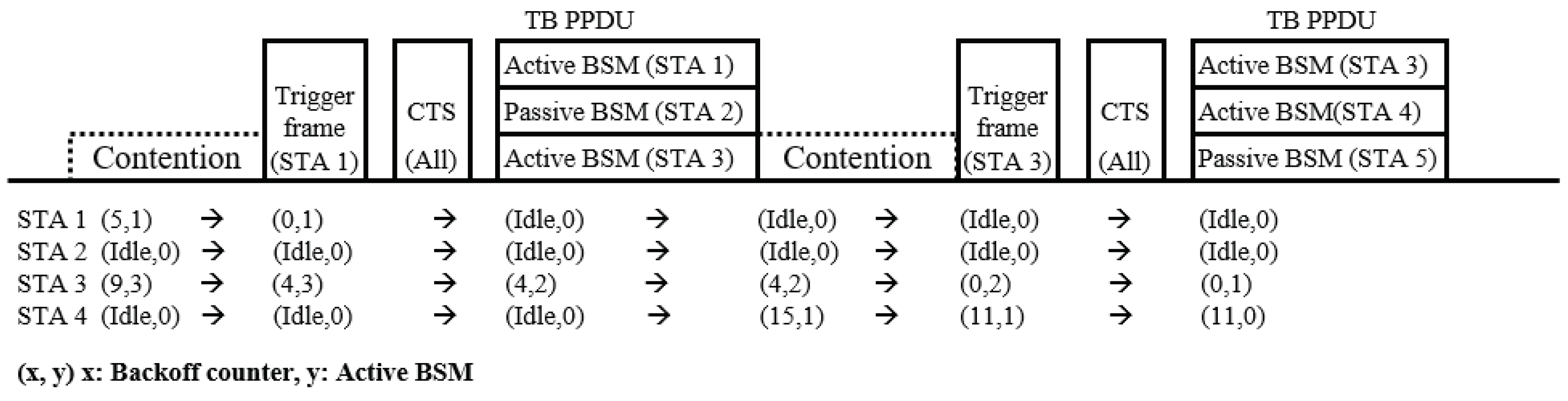
Since broadcast BSM is destined to all nearby VSTAs, all VSTAs within the transmission range of each transmitting VSTAs needs to be protected. Thus, in the proposed scheme, a protection procedure using MU-RTS is proceeded ahead of multi-vehicle BSM transmission. Since the MU-RTS protection in DTA is always intended to all neighboring VSTAs, the Common Info field can contain all the necessary information for MU-RTS procedure without User Info List field. Furthermore, as the Common Info field information of the MU-RTS frame can be reused for the TF soliciting TB PPDU transmission of BSM, the TF for MU-RTS procedure and that for multi-vehicle BSM triggering can be merged into one unified TF. Thus, once a triggering VSTA transmits a TF, all VSTAs that receive the TF transmit simultaneous CTS immediately after the TF reception, following that a simultaneous TB PPDU transmission is made by the scheduled VSTAs. Within the User Info List field of the TF, RU scheduling information for multi-vehicle BSM transmission is included, and the triggering VSTA reserves one of the scheduled RUs for the BSM transmission of itself. If the triggering VSTA does not receive any CTS frame in response to the TF, the VSTA considers the TF transmission has failed and invokes another backoff procedure. In this case, however, the VSTA does not change the current contention window size as the previous backoff procedure was invoked by a broadcast frame. An example of the proposed DTA transmission sequence is described in
Figure 3.
In the proposed BSM dissemination scenario, there exist a few issues that need to be resolved to improve the performance of DTA. First, a triggering VSTA should know which VSTA has a BSM to transmit. If a VSTA with empty buffer is triggered, the scheduled RU might be wasted resulting in poor channel use. However, if a network topology changes rapidly or the number of VSTAs is large, it is difficult for the triggering VSTA to maintain the information on the network traffic consistently. Secondly, the transmitting VSTA does not know if the transmission has succeeded as there is no acknowledgement from the receivers. As soon as a VSTA transmits a BSM, the VSTA removes the transmitted packet from the buffer. If a collision occurs in the channel, the BSM is lost and there is no way to recover it. This can be a very serious problem under high vehicle density since the collision probability increases rapidly as the density increases [
35].
To overcome such difficulties, in the proposed scheme, VSTA manages its buffered BSMs with two categories, the active BSM and the non-active BSM. VSTA considers a BSM is active if it has not been transmitted yet. If a VSTA has an active BSM, it performs EDCA backoff procedure to actively acquire the channel. Once the VSTA transmits the active BSM by means of either EDCA or TA, the BSM is no longer active. If the VSTA has no additional active BSM in the buffer, the VSTA keeps the BSM as a non-active BSM, otherwise the BSM is discarded. The VSTA does not initiate an EDCA backoff procedure for the non-active BSM, but it can be transmitted by TA. By doing so, waste of RU can be prevented since all VSTAs always have BSM to transmit. Moreover, since BSMs can be retransmitted by TA, the BSM delivery rate can be improved without increasing the channel contention. As a triggering VSTA does not need to consider the buffer status of other VSTAs, in the proposed scheme, we assume that the triggering VSTA performs a round robin scheduling among VSTAs within a predefined triggering range based on the positioning information.
In the next section, a mathematical model for the analysis of the proposed scheme is provided.
3. Numerical Analysis
In this section, we provide the numerical analysis of the proposed DTA scheme. The goal of this section is to obtain the transmission delay of the proposed scheme. In order to do so, we provide the Markov chain analysis of the proposed scheme and the Probability Generating Function (PGF) of the service time of a BSM using M/G/1 queuing model.
In this paper, the impact of the mobility of VSTAs is not considered, since VSTAs are almost stationary within one packet transmission time in platooning communication. According to [
36], high mobility of nodes (up to 120 mph) has very minor impact on the performance of the one-hop direct message broadcast network with high data rates. Also, in order to concentrate on the effect of the vehicle density and traffic intensity on the delay aspect and packet delivery rate of the proposed scheme, we only considers the packet collision and the hidden terminal effect and neglect the packet error rate as well as the capture effect [
37] in this analysis.
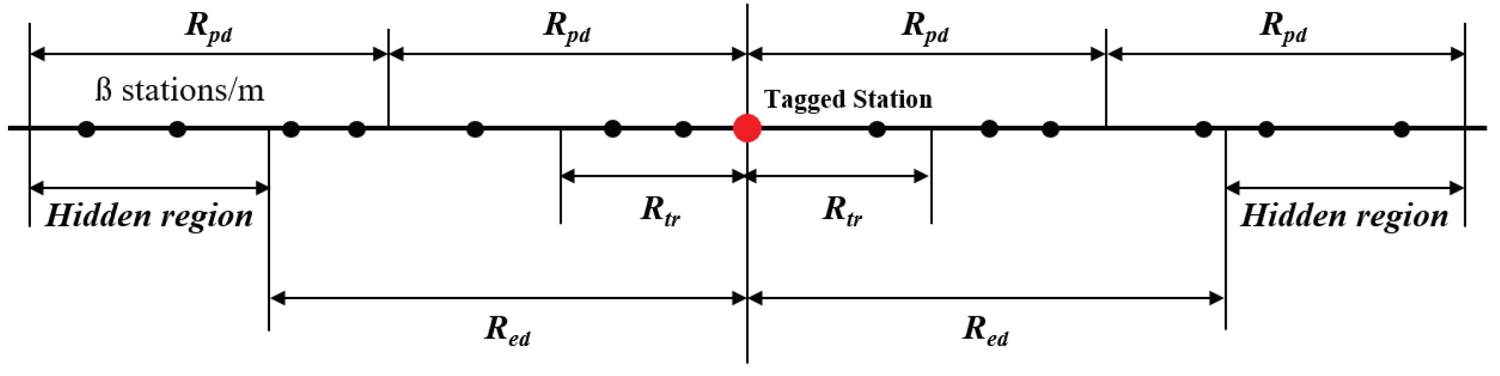
In this paper, we consider a one-dimensional highway model for our numerical analysis as shown in
Figure 4. For inter-VSTA distance, an exponential distribution is applied, assuming that the VSTAs are placed on the line according to a Poisson point process with network density
(in VSTAs per meter). From the definition of Poisson distribution, the probability of j VSTAs existing within length L,
, is given by
The IEEE 802.11 specification defines two types of carrier sensing: Preamble Detection (PD) and Energy Detection (ED). A channel is considered busy as PD, when the preamble of a PPDU, e.g., the Short Training Field (STF), is detected by the physical layer of the receiver. If a preamble is detected, the receiving VSTA can obtain necessary information to decode the MAC-layer Protocol Data Unit (MPDU) of the PPDU. Unless the Frame Check Sequence of the MPDU fails caused by the channel error, the transmission is regarded as success. Nevertheless, the received power of a PPDU is not sufficient to detect the preamble, the recipient may be aware of the presence of ongoing transmission on the channel. If an energy is detected and is greater than a threshold value, the receiving VSTA regards the channel as busy and waits until the energy level decreases less than the threshold.
Regarding the relationship between the radio range and transmission power, we apply the same approach as described in [
24]. Assuming all VSTAs have the same transmission power and receiver sensitivity, the ED range of a transmission,
, is greater than the PD range,
. By assuming the interference range greater than
and less than
, the VSTAs within the region
, become hidden VSTAs of which the transmission might cause an interference to the tagged VSTAs if the transmission duration is overlapped to each other.
Based on the assumption, the average number of VSTAs in the triggering region,
, the PD region,
, the ED region,
, and the hidden region,
, can be respectively obtained as the following:
In DTA, VSTA can transmit a BSM using two methods: (1) EDCA: the VSTA becomes the TXOP holder by backoff contention and transmits a Trigger frame followed by a BSM transmission using a scheduled RU, (2) Triggered Access: transmitting a BSM in response to a Trigger frame from other VSTAs. Since all transmission sequences are initiated by the EDCA transmission, the backoff procedure needs to be analyzed first.
According to the IEEE 802.11 standard, broadcast frames, such as BSM, do not require an acknowledgement from the recipients, so the transmitter cannot determine whether the transmission has succeeded or not. As there is no change on the contention window size of the transmitter, the EDCA procedure with the fixed contention windows size,
W, can be modeled as one-dimensional Markov chain model as depicted in
Figure 5 [
38]. In
Figure 5,
,
and
denote the probability of a packet arrival from the higher layer during a virtual time slot [
39],
, the probability that no active BSM exists in the queue and the backoff blocking probability [
40], respectively.
Denoting the rate of generating a BSM to
,
can be given by
The backoff blocking probability,
, is the probability that the backoff counter of the tagged VSTA is frozen by other VSTAs occupying the channel or by other ACs. In this paper, the target BSM message is supposed to use the highest AC, the impact of internal contention within a STA is not considered. By the definition of
, we have
In (
4),
is the transmission probability that a VSTA transmits a frame in a randomly chosen time slot [
38], and can be obtained by solving the Markov chain model of the proposed scheme in
Figure 5.
According to the stationary distribution of the Markov model in
Figure 5, we have
Unlike conventional EDCA transmissions, in DTA, a VSTA may transmit an active BSM with non-zero backoff counter by the triggered access from other VSTAs. In this case, the backoff procedure is resumed after the triggered access, but the VSTA does not transmit a BSM when its counter reaches to zero unless there exists an active BSM in the buffer. In the proposed scheme, therefore, an EDCA transmission event occurs when one of the following conditions is met: (1) the VSTA has more than one active BSM, (2) the VSTA has one active BSM and no triggered access happens during the backoff procedure, (3) the only active BSM is transmitted by an triggered access during the backoff procedure, and another active BSM arrives before the counter reaches to zero. In this paper, we consider the probability that multiple triggered access scheduling events or packet arrival events occur during one backoff procedure is negligible. According to [
41] the steady-state probability that
k packets exist in the system,
is
where
is the busy probability of the system which can be derived by
where
is the average service rate of the proposed scheme.
Thus, denoting the probability that a VSTA has at least one active BSM to transmit when the counter reaches to zero as
, we have
and we can obtain
and
as
and
In (
9),
, is the probability that a VSTA transmits a BSM by triggered access in an arbitrary virtual time slot. A VSTA transmits a BSM via triggered access when it successfully receives a TF containing the scheduling information of the VSTA which means that the received TF is transmitted within
and the VSTA is included in
M, the number of RUs for triggering, out of
VSTAs. An EDCA transmission is regarded successful if only one VSTA transmits the Trigger frame within the ED range at the time slot, and no transmission occurs from the VSTAs in the hidden range during the vulnerable period [
26]. Once a TF is transmitted successfully, all nearby VSTAs within
are supposed to transmit CTS frame simultaneously followed by the triggered access TB PPDU transmission of scheduled VSTAs. As long as the TF is not collided, the whole DTA transmission sequence will take place, so only the duration of the TF affects the vulnerable period. If we let
be the probability that a VSTA successfully transmits a TF in an arbitrary time slot, we have
where
denotes the vulnerable period of a TF that can be given by
where
is the duration of the PPDU containing the TF.
Then, the probability that the tagged STA successfully participate in a triggered access transmission,
, can be given by
Now, we calculate the average virtual slot,
. Based on the procedure of the proposed scheme, there are three types of possible virtual slots: (1) empty slots where all VSTAs are in backoff procedure or idle, (2) DTA successful slot and (3) MU-RTS collision slot with the duration
,
and
, respectively, and we have
where
,
,
and
denotes the duration of AIFS, SIFS, the PPDU carrying a CTS frame and the TB PPDU containing multi-vehicle BSM frames, respectively.
Letting
,
and
be the probabilities corresponding to the above slots, respectively, we have
To simplify the analysis, in this paper, we neglect transmission events occurring outside of the interference range.
To calculate the service rate of the proposed scheme,
, we model the transmission procedure of the proposed scheme as an M/G/1 queue with unlimited queue and apply the Probability Generating Function (PGF) approach. As treated in [
24], the service time of a packet can be modeled as a non-negative random variable denoted by
S, with the unit of the smallest time unit,
.
We first provide the PGF of active BSM transmission procedure. Whenever a VSTA has an active BSM a backoff procedure is initiated. Therefore, the generalized state transition diagram of the service time of the BSM that has become the head of the queue can be modeled as depicted in
Figure 6.
In
Figure 6,
,
and
denote the PGF of the transmission sequence duration of a triggering VSTA, the PGF of the transmission duration of MU-RTS collision case and the PGF of the time that the backoff counter decrements by one, respectively.
By the definition of the model,
and
can be given by
Using (
14), (
15) and (
16),
can be given by
There are two main differences between the state transition model of the proposed scheme and the general EDCA model provided in [
26,
27]. First, the traffic can transition to end state from any state due to the triggered access, Second, the state-in probability from the start point is no longer uniformly distributed, because of the residual backoff counter after a triggered access.
In
Figure 6,
denotes the PGF of the transmission sequence duration of a triggered VSTA, and can be obtained as
If an active BSM in service is transmitted via triggered access during the backoff procedure and another active BSM exists in the queue, the next serving BSM can use the residual backoff counter so that the service time can be reduced. Therefore, whether a BSM initiates a backoff procedure or reuses the previous backoff procedure depends on the number of buffered BSM. Using the steady-state probability (
7), we can calculate the initial state-in probability for state
k,
, as follows
In (
20),
is the probability that the residual backoff counter of the previous active BSM is
k which can be given by
Applying Mason’s formula, there exists
loops in the proposed transition model. Since all loops in the model touch each other at least once, the determinant of the transition model, Δ can be given by
For state
k, there exists
paths that exits the system via state
k, and each path equally touches the right most
loops sharing the same cofactor value of the determinant,
. If we let
be the cofactor value for the paths exiting the system via state
k, we have
If we denote the sum of gains of all paths with respect to
by
,
As a result, the PGF of the service time,
, can be given by
Finally, using the property of PGF, the average service time,
, can be derived as
According to the Pollaczek–Khintchine mean value formula [
41] for M/G/1 queue, the average queuing delay,
, can be derived by
Thus, using (
25)–(
27), the average transmission delay
can be obtained by
4. Performance Evaluation
In this section, we discuss the performance evaluation of the proposed scheme is discussed. For the performance evaluation of the proposed scheme, an event-driven MAC level simulator has been developed in Matlab which implements IEEE 802.11 EDCA functions and IEEE 802.11ax TUA functions based on the proposed physical layer numerology of IEEE 802.11bd discussed in
Section 2.
In the tested scenario, all VSTAs are located on a one-dimensional highway with the total length of 5000 m as depicted in
Figure 4, and the performance is measured for the centered 3000 m. It is assumed that the VSTAs are equipped with a Global Positioning System (GPS) and the wireless communication module with parameters shown in
Table 1. In the simulation, the rate of successful packet transmission of DTA and the conventional EDCA are compared. As discussed in
Section 2, since an ideal physical channel condition is assumed, the packet error rate and the mobility of VSTAs are not considered, the main focus is the performance impact of packet collision given the VSTA density varies from 0.03 to 0.12. Following the typical characteristics of BSM traffic employed in related works [
21,
26,
27,
33,
42], 200 Bytes payload size and 10 Hz arrival rate BSM traffic is considered to be moderate data traffic in the simulation. In addition, in order to emulate future platooning environments with higher requirements, 400 Bytes payload size and 20 Hz arrival rate BSM traffic is used for the simulation as heavy data traffic. To observe the trade-off between the number of multiplexed VSTAs and the airtime of the TB PPDU, 3 and 9 RUs per one DTA sequence are tested.
Figure 7 shows the active BSM transmission success rate of the proposed scheme that a BSM is transmitted and delivered to all receivers within the PD range. According to the figure, DTA always shows better performance than the legacy 802.11p EDCA scheme as long as the contention window size and the number of scheduled RUs per transmission is large enough. In case of low vehicle density, the proposed scheme guarantees successful delivery for greater than 90% of the generated BSMs, and in the most extreme case, high vehicle density (0.12) and heavy data traffic (
: 400 B,
: 20 Hz), DTA successfully transmits more than 20% of the generated BSMs improving the transmission success rate by twice of EDCA performance.
One remark is that as soon as the EDCA channel access intensity dominates the effect of the contention window, the performance degrades fast because the extended duration of TB PPDU makes it more vulnerable from hidden VSTAs transmission. Therefore, setting an appropriate contention window size can be critical to fully exploit the advantages of DTA.
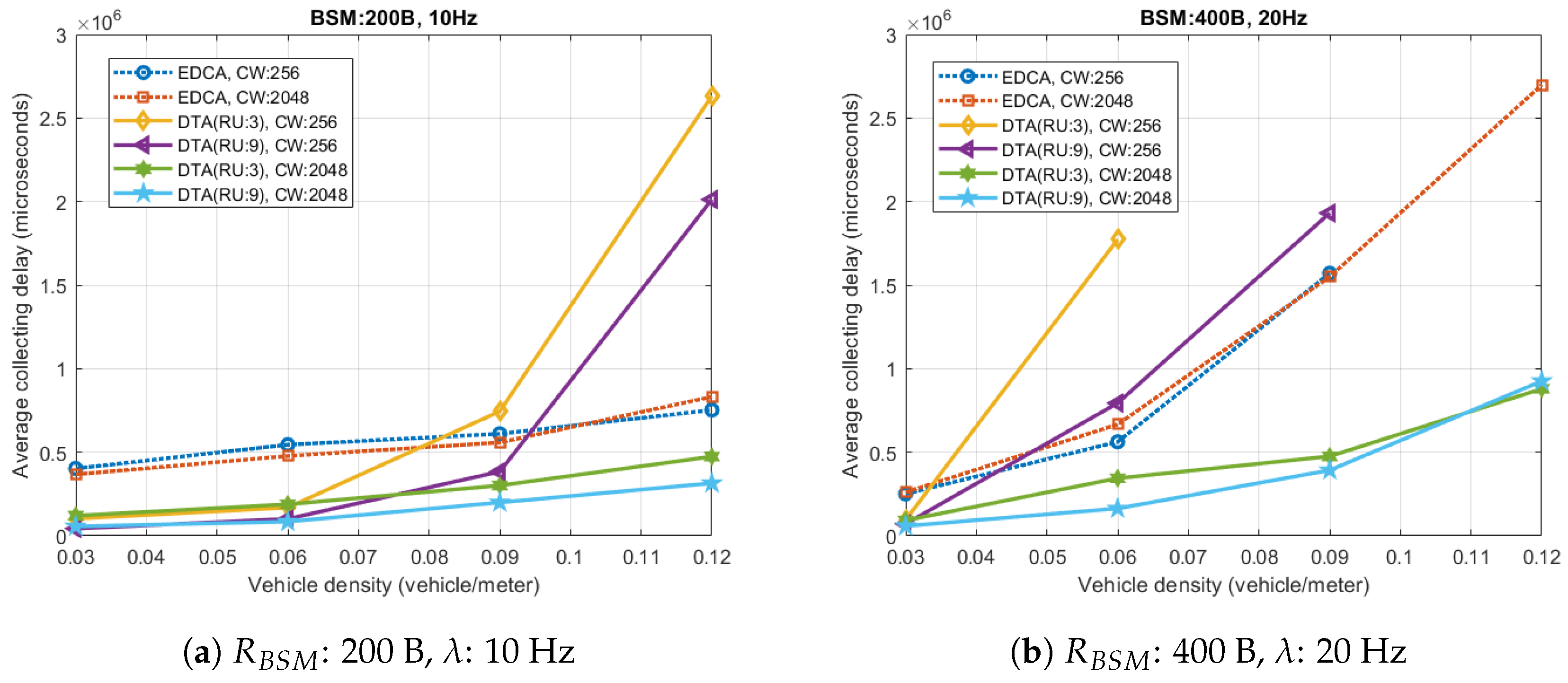
Figure 8 depicts the average BSM collecting delay for which a VSTA collects BSMs of all VSTAs within the PD range. How quickly VSTA can obtain the information of nearby vehicles can be one of the most important performance indicators in BSM dissemination scenario.
Figure 8 shows that the proposed scheme greatly improves the collecting delay compare to the conventional scheme especially for extreme condition (high vehicle density 0.12) and heavy data traffic (BSM: 400 B, 20 Hz). In
Figure 8b, the delay of the proposed scheme for the highest vehicle density is three times smaller than that of EDCA (0.92 and 2.69 s). Also, the proposed scheme with large contention window (CW: 2048) outperforms EDCA throughout the all measured vehicle density range.
The figure proves that our proposed scheme deals with heavy congestion very well. It is observed that the collecting delay of EDCA scheme increases drastically as the vehicle density increases for heavy traffic case, and the maximum difference of the collecting delay between the moderate traffic case (
Figure 8a) and the heavy traffic case (
Figure 8b) reaches to 1.9 s. On the other hand, the maximum difference of the proposed scheme remains less than 0.7 s when the contention window size is sufficiently high.
Furthermore, in low vehicle density condition, DTA allows VSTAs to collect all BSMs within very short period (58 ms), even shorter than the arrival rate of BSM (100 ms), since VSTA can obtain multiple BSMs from one TXOP. In EDCA, since BSM cannot be retransmitted, if a VSTA fails to receive a BSM it should wait until the next BSM is generated. For this reason, Thus, if a VSTA experiences consecutive transmission failures, the neighboring VSTAs might lose the tracking information for the VSTA increasing the probability of accident. By transmitting non-active BSM triggered by other VSTA, such problem can be avoided without increasing channel contention overhead.
Figure 9 depicts various performance statistics to provide better understanding on the performance results shown in
Figure 7 and
Figure 8.
Figure 9a shows that DTA (CW: 2048, RU: 9) tremendously improves the transmission success probability by 0.45 compare to EDCA with the same contention window. Consequently, nevertheless the transmission delay increases, the overall BSM delivery performance can be increased.
Focusing on the delay aspect, the result seems that a major portion of the transmission delay is caused by the queuing delay in high vehicle density case. In case the vehicle density is less than 0.09, since the total transmission delay is less than the packet arrival interval, only a very small amount of queuing delay occurs for all cases (except DTA with smaller contention window). On the other hand, as the transmission delay exceeds the arrival rate, the queuing delay starts increase rapidly. In this case, the increment of the proposed scheme is relatively greater than EDCA, because in DTA, as a transmitting VSTA can detect the failure of a TF by the MU-RTS procedure, it cancels the transmission and keep the serving BSM for new backoff procedure. Despite the increased transmission delay, the improvement of the transmission success probability effectively compensates for the overall performance of the proposed scheme.
When it comes to the number of RUs, the result shows a trade-off between the transmission success probability and the transmission delay. According to
Figure 9a,b, DTA with smaller number of RUs shows better performance in terms of transmission success probability due to shorter PPDU duration. On the other hands, DTA with greater number of RUs has shorter transmission delay, as it can serve a greater number of BSMs with one medium contention. Therefore, the number of RUs needs to be optimized based on the characteristics of the target application in real world implementation.
Figure 10 depicts the ratio between DTA and EDCA among successful transmissions. The figure shows that in DTA, the number of EDCA transmission is greatly reduced as the number of RUs for scheduling increases. Even in non-saturated condition, where the vehicle density is low (0.3) and the BSM traffic is high (400 B, 20 Hz), the number of EDCA transmission is decreased by 71% while the total number of transmission success is greatly increased. This incurs that the scheduling of DTA efficiently relieves the channel access intensity of nearby VSTAs. Moreover, under extremely saturated condition (high vehicle density (0.12) and heavy data traffic (
: 400 B,
: 20 Hz)), upto 87% of successful transmission is served by triggered access, while the transmission success rate is increased by 94% than legacy EDCA only case. The result proves that the proposed scheme effectively raise the channel use.
Figure 11 shows the portion of active and non-active BSM among successful transmission. The figure shows that non-active BSM takes a large portion of transmission success when the medium is not saturated. As we discussed before, non-active BSM helps VSTAs to collect BSMs much faster. Additionally, this can be advantageous since scheduled RU can be used adaptively depending on the situation. For example, if a platooning scenario requires VSTAs to maintain the neighbor information with short valid time, VSTAs can be configured to transmit non-active BSMs aggressively. On the other hand, if the BSM requirement is not demanding but VSTAs are running multiple applications, the non-active BSM portion can be used to transmit data which is lower prioritized than BSM.
Figure 12 shows the performance impact of the payload size and the arrival rate.
Figure 12a depicts the transmission success rate of active BSM with variable payload size. According to the figure, with greater payload size (
: 400 B), DTA always outperforms EDCA, and the performance gap increases as the vehicle density increases. The result shows that DTA with greater payload size (
: 400 B) has almost same performance as EDCA with smaller payload size (
: 200 B).
Figure 12b also shows that DTA provides enhanced performance regardless of the arrival rate. From lower arrival rate case (
: 10 Hz), it is observed that DTA and EDCA have similar gradient in low vehicle density region. In such case, the probability that more than one VSTA accesses the channel at the same timeslot is extremely low. Therefore, it is expected that the performance gap is purely caused by the protection of MU-RTS from hidden VSTA. As the vehicle density increases, channel gets busier, so the performance gain from triggered access multiplexing increases as we already discussed in
Figure 9.


