Article

Free Damping Vibration of Piezoelectric Cantilever Beams: A Biparametric Perturbation Solution and Its Experimental Verification

1
School of Civil Engineering, Chongqing University, Chongqing 400045, China
2
Key Laboratory of New Technology for Construction of Cities in Mountain Area (Chongqing University), Ministry of Education, Chongqing 400045, China
*
Author to whom correspondence should be addressed.
Appl. Sci. 2020, 10(1), 215; https://doi.org/10.3390/app10010215
Submission received: 24 November 2019 / Revised: 22 December 2019 / Accepted: 24 December 2019 / Published: 26 December 2019
(This article belongs to the Special Issue Homogenization Methods in Materials and Structures)

Abstract

:
As an intelligent material, piezoelectric materials have been widely used in many intelligent fields, especially in the analysis and design of sensors and actuators; however, the vibration problems of the corresponding structures made of the piezoelectric materials are often difficult to solve analytically, because of their force–electric coupling characteristics. In this paper, the biparametric perturbation method was used to solve the free damping vibration problem of piezoelectric cantilever beams, and the perturbation solution of the problem solved here was given. A numerical example was given to discuss the influence of the piezoelectric properties on the vibration of piezoelectric cantilever beams. In addition, related vibration experiments of the piezoelectric cantilever beams were carried out, and the experimental results were in good agreement with the theoretical results. The results indicated that the biparametric perturbation solution obtained in this study is effective, and it may serve as a theoretical reference for the design of sensors and actuators made of piezoelectric materials.

Graphical Abstract

1. Introduction

Piezoelectric materials, as an intelligent material, have been widely used in the manufacture of many intelligent devices, such as sensors, actuators, and transducers [1,2,3]. The working principle of piezoelectric sensors and piezoelectric actuators depends mainly on the conversion between force and electricity in the vibration process of piezoelectric materials [4,5]. Thus, an understanding of the vibration problems of the piezoelectric structures is the premise for designing piezoelectric sensors and piezoelectric actuators. However, the vibration problems of the piezoelectric structures are often difficult to solve analytically, because of the force–electric coupling characteristics of piezoelectric materials. So, it is necessary and meaningful to find an efficient analytical method for solving the vibration problems of piezoelectric structures and to give their analytical solutions.
In the existing works, many researchers have studied the vibration problems of piezoelectric structures, and some achievements have been made. Mahinzare et al. [6] studied the free vibration of a rotating circular nanoplate made of two directional functionally graded piezo materials (two directional FGPM) based on the first shear deformation theory (FSDT). Przybylski and Gasiorski [7] presented theoretical and experimental investigations into the nonlinear flexural vibrations of a structure composed of a host beam with piezoelectric ceramic actuators symmetrically bonded to its top and bottom surfaces. Liu et al. [8] studied the dynamic analytical solution of a piezoelectric stack utilized in an actuator and a generator based on the linear piezo-elasticity theory. Parashar et al. [9] studied the nonlinear shear-induced flexural vibrations of piezoceramic actuators. Mukherjee and Chaudhuri [10] demonstrated the effect of large deformations on piezoelectric materials and structures under time varying loads. Chen et al. [11] studied the natural vibration and transient response of a functionally graded piezoelectric material (FGPM) curved beam with a numerical method. Dong et al. [12] discussed the influence that piezoelectric materials exert on the vibration behavior of a stepped cantilever beam with surface bonded or embedded piezoelectric materials. Li et al. [13] studied the free vibration of statically thermal post-buckled functionally graded material beams with surface-bonded piezoelectric layers subjected to both temperature rise and voltage. Oh et al. [14] investigated the post buckling and vibration characteristics of a piezolaminated composite plate subjected to thermo-piezoelectric loads. Li and Shi [15] studied the free vibration of the piezoelectric-elastic laminated beams by combining the state-space method and differential quadrature method. Lu et al. [16] derived the free vibration frequency of the state space solution and the solution for a simple support piezoelectric laminated beam. Chen et al. [17] presented a new method of a state-space-based differential quadrature for free vibration of generally laminated beams. Kapuria and Alam [18] presented a one-dimensional beam finite element with electric degrees of freedom for the dynamic analysis of hybrid piezoelectric beams, using the coupled efficient layer wise theory. The summation of the results of the existing works shows that there are only a few related vibration experiments of piezoelectric structures, which means that the reliability of the analytical solution cannot be guaranteed sufficiently. Moreover, there has been no unified and effective method for solving the vibration problems of piezoelectric structures.
The parameter perturbation method is a general analysis method for solving approximate solutions of nonlinear mechanical problems, which was first used to calculate the influence of the small celestial body on the motion of the large object, and has been widely used in the theoretical research of physics and mechanics. Parameter selection is an important problem while using the parameter perturbation method. In order to solve the difficulty of parameter selection, Chen and Li [19] put forward the concept of the free parameter perturbation method, that is, there is no need to point out the physical meaning of the perturbation parameters during perturbation, which provides a new idea for solving the parameter selection problem of the parameter perturbation method. Lian et al. [20] solved the Hencky membrane problem without a small-rotation-angle assumption by using a single-parameter perturbation method. There are many perturbation methods based on a single parameter, which are not described in detail here. For the difficulty in the selection of the perturbation parameters, another idea is to select multiple parameters, that is, the so-called “multi-parameter perturbation method”. For the multi-parameter perturbation method, Nowinski and Ismail [21] solved the cylindrical orthotropic circular plate problem under a uniform load by using the biparametric perturbation method. The application of the multi-parameter perturbation method in beam problem was proposed by Professor Chien [22] in 2002, and the classical Euler–Bernoulli beam equation was solved by using the load and height difference of the beam as the perturbation parameters. Later, He and Chen [23] simplified the bending moment by using the quasi linear analysis method, so that the parameter perturbation process was directly aimed at the algebra equation rather than the integral equation, which greatly simplified the perturbation process. Recently, He et al. [24,25] comprehensively analyzed the large deflection problem of beams with a height difference under various boundary conditions, and put forward the so-called “biparametric perturbation method” definitely, and successfully applied this method to the solution of the bimodular von-Kármán thin plate equation. So far, the application of the biparametric perturbation method in the vibration problems of piezoelectric structures has not been reported.
In this study, we will derive the theoretical solution of the free damping vibration problem of the piezoelectric cantilever beams by the biparametric perturbation method and perform the related vibration experiments to verify the validity of the theoretical solution presented here. The whole paper is organized as follows. In Section 2, the mechanical model and the basic equations of the free damping vibration problem of piezoelectric cantilever beams will be established, the piezoelectric parameter and damping coefficient will be selected as the perturbed parameters, and the theoretical solution of the problem studied here will be given. A comparison of the theoretical solution and the existing solution will be presented, and the influence of the piezoelectric properties will be analyzed and discussed in the Section 3. Next, in Section 4, we will show the related vibration experiments of the piezoelectric cantilever beam and compare the experimental results with the theoretical results. According to the results mentioned above, some main conclusions will be drawn in Section 5.

2. The Basic Equations and Biparametric Perturbation Solution

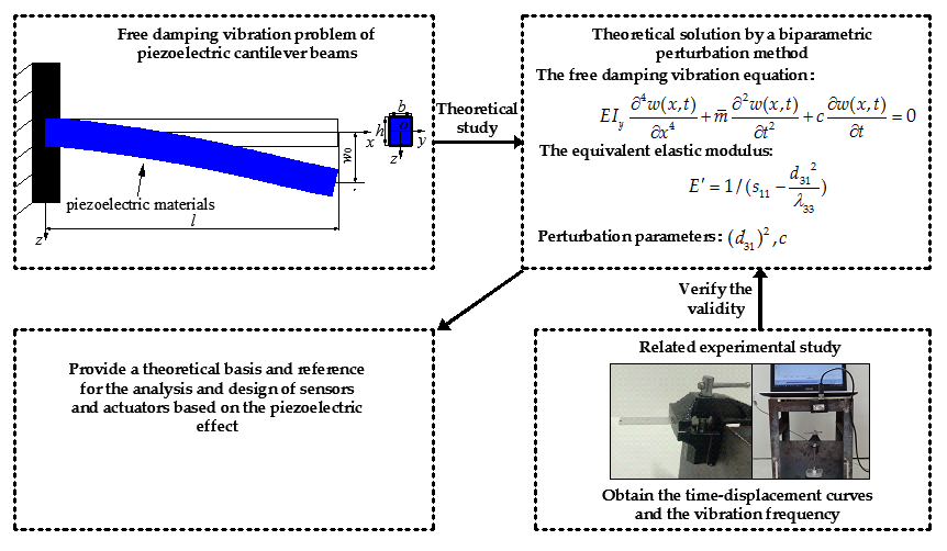
2.1. The Mechanical Model and Basic Equations

A piezoelectric strip with isotropy in plane x y and anisotropy in plane x z is clamped at the left end in order to construct a cantilever beam whose length is l, width is b, thickness is h, and uniformly-distributed mass is m ¯ . Then, an initial displacement w 0 is given at the right end of the piezoelectric cantilever beam, and the piezoelectric cantilever beam will generate a free damping vibration under the drive of the initial displacement, as shown in Figure 1.
From the literature [26], we can know that the free damping vibration equation of a general cantilever beam with equal cross section is as follows:
E I y 4 w ( x , t ) x 4 + m ¯ 2 w ( x , t ) t 2 + c w ( x , t ) t = 0 ,
in which E I y is the bending stiffness, c is the damping parameter, and c = 2 ξ m ¯ ω , in which, ξ is the damping ratio and ω is the vibration frequency. The boundary conditions are as follows:
{ w ( x , t ) = 0 w ( x , t ) x = 0 ,   at   x = 0
and
{ E I y 2 w ( x , t ) x 2 = 0 E I y 3 w ( x , t ) x 3 = 0 ,   at   x = l
and the initial conditions are as follows:
{ w ( x , t ) = w 0 w ( x , t ) t = 0 ,   at   x = l , t = 0 .
It should be noted that the beam considered here is a piezoelectric beam, thus E should be the equivalent elastic modulus under the coupling of the elastic and piezoelectric properties in a one-dimensional pure bending problem. The constitutive relations of the piezoelectric materials are, in a two-dimensional case, as follows:
{ ε x = s 11 σ x + s 13 σ z + d 31 E z ε z = s 13 σ x + s 33 σ z + d 33 E z γ z x = s 44 τ z x + d 15 E x
and
{ D x = d 15 τ z x + λ 11 E x D z = d 31 σ x + d 33 σ z + λ 33 E z ,
in which, σ x , σ z , and τ z x are the stress components; D x and D z are the electric displacement components; ε x , ε z , and γ z x are the strain components; E x and E z are the electric field intensity components; s 11 , s 13 , and s 33 are the flexibility coefficients; d 31 , d 33 , and d 15 are the piezoelectric coefficients; and λ 11 and λ 33 are the dielectric coefficients. For a one-dimensional pure bending problem, there is no stresses σ z and τ z x , as well as the corresponding strain ε z and γ z x , only existing σ x and ε x , from the point of view of deformation. Thus, the constitutive relations can be simplified as follows:
{ ε x = s 11 σ x + d 31 E z ε z = 0 γ z x = 0
and
{ D x = λ 11 E x D z = d 31 σ x + λ 33 E z .
Generally, D x D z and D z are very small a in one-dimensional problem. Thus, we can suppose D z 0 . From Equations (7) and (8), we may obtain the following:
E z = d 31 λ 33 σ x .
Substituting Equation (9) into Equation (7), one has the following:
ε x = ( s 11 λ 33 d 31 2 λ 33 ) σ x = σ x λ 33 / ( s 11 λ 33 d 31 2 ) = σ x E .
From Equation (10), we can know the equivalent elastic modulus is as follows:
E = 1 / ( s 11 d 31 2 λ 33 ) .
Thus, we can obtain the free damping vibration equation of the piezoelectric cantilever beam, only by substituting E for E in Equation (1), as follows:
E I y 4 w ( x , t ) x 4 + m ¯ 2 w ( x , t ) t 2 + c w ( x , t ) t = 0 .

2.2. The Biparametric Perturbation Solution

The basic equation, boundary conditions, and initial conditions are given above. Now, let us solve the basic equation. In order to solve Equation (12), the variable separation is required firstly, suppose the following:
w ( x , t ) = v ( x ) Y ( t ) .
Substituting Equation (13) into Equation (12), it can be obtained that
E I y Y ( t ) 4 v ( x ) x 4 + m ¯ v ( x ) 2 Y ( t ) t 2 + c v ( x ) Y ( t ) t = 0 .
By simplifying Equation (14), it can be transformed into the following:
v ( 4 ) ( x ) v ( x ) + m ¯ Y ( t ) + c Y ( t ) E I y Y ( t ) = 0 .
Here, we let
v ( 4 ) ( x ) v ( x ) = m ¯ Y ( t ) + c Y ( t ) E I y Y ( t ) = D 4 ,
in which D is the unknown constants. Two differential equations can be obtained, and they are as follows:
v ( 4 ) ( x ) D 4 v ( x ) = 0
and
Y ( t ) + c m ¯ Y ( t ) + ω 2 Y ( t ) = 0 ,
in which ω 2 = D 4 E I y / m ¯ . It is assumed that the solution of Equation (17) is in the form of
v ( x ) = K e s x .
From Equations (17) and (19), we can obtain the following:
v ( x ) = K 1 e i D x + K 2 e i D x + K 3 e D x + K 4 e D x .
Converting Equation (20) into the form of the trigonometric function and hyperbolic function, one has the following:
v ( x ) = A 1 sin ( D x ) + A 2 cos ( D x ) + A 3 sinh ( D x ) + A 4 cosh ( D x ) .
Substituting Equation (21) into Equations (2) and (3), respectively, we can obtain the following
A 2 = A 4 ,
A 1 = A 3 ,
A 2 = sin D l + sinh D l cos D l + cosh D l A 1
and
1 + cos ( D l ) cosh ( D l ) = 0 .
Thus, the solution of Equation (17) is
v ( x ) = A 1 [ sin D x sinh D x + sin D l + sinh D l cos D l + cosh D l ( cosh D x cos D x ) ] .
in which D = ω 2 m ¯ / I y E 4 .
Substituting Equation (11) into Equation (18), we can obtain the following:
( m ¯ λ 33 s 11 m ¯ d 31 2 ) d 2 Y d t 2 + ( λ 33 s 11 d 31 2 ) c d Y d t + D 4 λ 33 I y Y = 0 .
Here, we used the biparametric perturbation method to solve Equation (27), and selected ( d 31 ) 2 and c as the perturbation parameters, thus the Y ( t ) can be expressed as follows
Y ( t ) = Y 0 0 ( t ) + Y 1 I ( t ) ( d 31 ) 2 + Y 2 I ( t ) c + Y 1 II ( t ) ( d 31 ) 4 + Y 2 II ( t ) ( c ) 2 + Y 3 II ( t ) c ( d 31 ) 2 .
Substituting Equation (28) into Equation (27), and comparing the coefficients of [ ( d 31 ) 2 ] 0 and c 0 , we may obtain the zero-order perturbation equation
d 2 Y 0 0 d t 2 + D 4 I y m ¯ s 11 Y 0 0 = 0 .
The corresponding initial conditions are as follows
{ v ( x ) Y 0 0 ( t ) = w 0 v ( x ) Y 0 0 ( t ) = 0 ,   at   x = l , t = 0 .
The solution of Equation (29) is as follows
Y 0 0 ( t ) = B 1 sin ( ω 1 t ) + B 2 cos ( ω 1 t ) ,
in which ω 1 = D 4 I y / m ¯ s 11 , ω 1 is the vibration frequency of the cantilever beam without a piezoelectric property, and B 1 and B 2 are the undetermined constants that can be determined by Equation (30). Substituting Equation (31) into Equation (30), one has the following:
B 1 = 0 , B 2 = w 0 A 1 [ sin D l sinh D l + sin D l + sinh D l cos D l + cosh D l ( cosh D l cos D l ) ] .
Comparing the coefficients of ( d 31 ) 2 and ( c ) 1 , we may obtain the first-order perturbation equations as follows,
For ( d 31 ) 2 :
m ¯ λ 33 s 11 d 2 Y 1 I d t 2 m ¯ d 2 Y 0 0 d t 2 + D 4 λ 33 I y Y 1 I = 0 .
The corresponding initial conditions are as follows:
{ v ( x ) Y 1 I = 0 v ( x ) d Y 1 I d t = 0 ,   at   x = l , t = 0 .
Solving Equation (33), we may obtain the following:
Y 1 I ( t ) = B 3 sin ( ω 1 t ) + B 4 cos ( ω 1 t ) ω 1 2 λ 33 s 11 B 2 t sin ( ω 1 t ) ,
in which B 3 and B 4 are the undetermined constants that can be determined by Equation (34). Substituting Equation (35) into Equation (34), one has the following
B 3 = 0 , B 4 = 0 .
For ( c ) 1 :
d 2 Y 2 I d t 2 + 1 m ¯ d Y 0 0 d t + D 4 I y m ¯ s 11 Y 2 I = 0 .
The corresponding initial conditions are as follows
{ v ( x ) Y 2 I = 0 v ( x ) d Y 2 I d t = 0 ,   at   x = l , t = 0 .
Solving Equation (37), gives the following
Y 2 I ( t ) = B 5 sin ( ω 1 t ) + B 6 cos ( ω 1 t ) 1 2 m ¯ B 2 t cos ( ω 1 t ) ,
in which B 5 and B 6 are undetermined constants, which can be determined by Equation (38). From Equations (38) and (39), we can obtain the following:
B 5 = 1 2 m ¯ ω 1 B 2 , B 6 = 0 .
Comparing the coefficients of ( d 31 ) 4 , ( c ) 2 , and c ( d 31 ) 2 , we may obtain the second-order perturbation equations as follows,
For ( d 31 ) 4 :
m ¯ λ 33 s 11 d 2 Y 1 II d t 2 m ¯ d 2 Y 1 I d t 2 + D 4 λ 33 I y Y 1 II = 0 .
The corresponding initial conditions are as follows
{ v ( x ) Y 1 II = 0 v ( x ) d Y 1 II d t = 0 ,   at   x = l , t = 0 .
From Equation (41), it can be obtained that
Y 1 II = B 7 sin ( ω 1 t ) + B 8 cos ( ω 1 t ) 3 ω 1 8 ( λ 33 s 11 ) 2 B 2 t sin ( ω 1 t ) ( ω 1 ) 2 8 ( λ 33 s 11 ) 2 B 2 t 2 cos ( ω 1 t ) ,
in which B 7 and B 8 are undetermined constants, which can be determined by Equation (42). Substituting Equation (43) into Equation (42), one has the following
B 7 = 0 , B 8 = 0 .
For ( c ) 2 :
d 2 Y 2 II d t 2 + D 4 I y m ¯ s 11 Y 2 II = 1 m ¯ d Y 2 I d t .
The corresponding initial conditions are as follows:
{ v ( x ) Y 2 II = 0 v ( x ) d Y 2 II d t = 0 ,   at   x = l , t = 0 .
Solving Equation (45), we may obtain the following
Y 2 II ( t ) = B 9 sin ( ω 1 t ) + B 10 cos ( ω 1 t ) + 1 8 ( m ¯ ) 2 B 2 t 2 cos ( ω 1 t ) 1 8 ( m ¯ ) 2 ω 1 B 2 t sin ( ω 1 t ) ,
in which B 9 and B 10 are the undetermined constants, which can be determined by Equation (46). Substituting Equation (47) into Equation (46), gives the following
B 9 = 0 , B 10 = 0 .
For c ( d 31 ) 2 :
d 2 Y 3 II d t 2 + D 4 I y m ¯ s 11 Y 3 II = 1 m ¯ λ 33 s 11 B 2 ( ω 1 ) 2 t cos ( ω 1 t ) .
The corresponding initial conditions are as follows:
{ v ( x ) Y 3 II = 0 v ( x ) d Y 3 II d t = 0 ,   at   x = l , t = 0 .
From Equation (49), we can obtain the following:
Y 3 II = B 11 sin ( ω 1 t ) + B 12 cos ( ω 1 t ) + 1 4 m ¯ λ 33 s 11 B 2 ω 1 t 2 sin ( ω 1 t ) + 1 4 m ¯ λ 33 s 11 B 2 t cos ( ω 1 t ) .
in which B 11 and B 12 are undetermined constants, which can be determined by Equation (50). Substituting Equation (51) into Equation (50), one has the following:
B 11 = 1 4 m ¯ λ 33 s 11 ω 1 B 2 , B 12 = 0 .
Substituting the determined Y 0 0 ( t ) , Y 1 I ( t ) , Y 2 I ( t ) , Y 1 II ( t ) , Y 2 II ( t ) , and Y 3 II ( t ) into Equation (28), Y ( t ) can be written as follows
Y ( t ) = B 2 { cos ( ω 1 t ) ω 1 2 λ 33 s 11 t sin ( ω 1 t ) ( d 31 ) 2 + [ 1 2 m ¯ ω 1 sin ( ω 1 t ) 1 2 m ¯ t cos ( ω 1 t ) ] c [ 3 ω 1 8 ( λ 33 s 11 ) 2 t sin ( ω 1 t ) + ( ω 1 ) 2 8 ( λ 33 s 11 ) 2 t 2 cos ( ω 1 t ) ] ( d 31 ) 4 + [ 1 8 ( m ¯ ) 2 t 2 cos ( ω 1 t ) 1 8 ( m ¯ ) 2 ω 1 t sin ( ω 1 t ) ] ( c ) 2 + [ 1 4 m ¯ λ 33 s 11 ω 1 t 2 sin ( ω 1 t ) + 1 4 m ¯ λ 33 s 11 t cos ( ω 1 t ) 1 4 m ¯ λ 33 s 11 ω 1 sin ( ω 1 t ) ] c ( d 31 ) 2 } .
Substituting Equations (26) and (53) into Equation (13), we can obtain the following:
w ( x , t ) = B 2 A 1 [ sin D x sinh D x + sin D l + sinh D l cos D l + cosh D l ( cosh D x cos D x ) ] { cos ( ω 1 t ) ω 1 2 λ 33 s 11 t sin ( ω 1 t ) ( d 31 ) 2 + [ 1 2 m ¯ ω 1 sin ( ω 1 t ) 1 2 m ¯ t cos ( ω 1 t ) ] c [ 3 ω 1 8 ( λ 33 s 11 ) 2 t sin ( ω 1 t ) + ( ω 1 ) 2 8 ( λ 33 s 11 ) 2 t 2 cos ( ω 1 t ) ] ( d 31 ) 4 + [ 1 8 ( m ¯ ) 2 t 2 cos ( ω 1 t ) 1 8 ( m ¯ ) 2 ω 1 t sin ( ω 1 t ) ] ( c ) 2 + [ 1 4 m ¯ λ 33 s 11 ω 1 t 2 sin ( ω 1 t ) + 1 4 m ¯ λ 33 s 11 t cos ( ω 1 t ) 1 4 m ¯ λ 33 s 11 ω 1 sin ( ω 1 t ) ] c ( d 31 ) 2 } .
Equations (32) and (54) can be transformed into the following:
w ( x , t ) = w 0 [ sin D x sinh D x + sin D l + sinh D l cos D l + cosh D l ( cosh D x cos D x ) ] [ sin D l sinh D l + sin D l + sinh D l cos D l + cosh D l ( cosh D l cos D l ) ] { cos ( ω 1 t ) ω 1 2 λ 33 s 11 t sin ( ω 1 t ) ( d 31 ) 2 + [ 1 2 m ¯ ω 1 sin ( ω 1 t ) 1 2 m ¯ t cos ( ω 1 t ) ] c [ 3 ω 1 8 ( λ 33 s 11 ) 2 t sin ( ω 1 t ) + ( ω 1 ) 2 8 ( λ 33 s 11 ) 2 t 2 cos ( ω 1 t ) ] ( d 31 ) 4 + [ 1 8 ( m ¯ ) 2 t 2 cos ( ω 1 t ) 1 8 ( m ¯ ) 2 ω 1 t sin ( ω 1 t ) ] ( c ) 2 + [ 1 4 m ¯ λ 33 s 11 ω 1 t 2 sin ( ω 1 t ) + 1 4 m ¯ λ 33 s 11 t cos ( ω 1 t ) 1 4 m ¯ λ 33 s 11 ω 1 sin ( ω 1 t ) ] c ( d 31 ) 2 } .
The vibration frequency of the piezoelectric cantilever beam is as follows:
ω = D 4 E I y m ¯ .
in which D can be determined by Equation (25). Thus, the free damping vibration problem of the piezoelectric cantilever beams is solved.

3. Comparison with the Existing Theory

To verify the validity of the theoretical solution obtained in this paper, we compared the solution presented here with the solution in the literature [26]. In the literature [26], the solution of the free vibration of the general cantilever beam is given. In order to facilitate the comparison, we degraded the problem solved here to the problem of the general cantilever beam, that is, let
d 31 = 0 , c = 0 .
Substituting Equation (57) into Equations (55) and (56), respectively, we may obtain the following
w ( x , t ) = [ sin D x sinh D x + sin D l + sinh D l cos D l + cosh D l ( cosh D x cos D x ) ] [ sin D l sinh D l + sin D l + sinh D l cos D l + cosh D l ( cosh D l cos D l ) ] w 0 cos ( ω 1 t )
and
ω = D 4 I y m ¯ s 11 .
From Equation (32), w ( x , t ) can be transformed into the following
w ( x , t ) = B 2 cos ( ω 1 t ) A 1 [ sin D x sinh D x + sin D l + sinh D l cos D l + cosh D l ( cosh D x cos D x ) ] .
For general materials, one has the following:
E = 1 s 11 .
Thus, we can obtain the following:
ω = D 4 E I y m ¯ .
Comparing Equations (60) and (62) with the expressions of the vibration displacement and frequency presented in the literature [26], it can be found that they are exactly the same. This shows that the solution in this paper, to a certain extent, is effective.
Equation (56) is the expression of the vibration frequency of the piezoelectric cantilever beam, and Equation (62) is the expression of the vibration frequency of the cantilever beam without piezoelectric properties. Comparing Equations (56) and (62), it can be found that ω = D 4 E I y / m ¯ < ω = D 4 E I y / m ¯ . This shows that the piezoelectric properties will increase the vibration frequency of the free vibration of the piezoelectric cantilever beams.

4. Experimental Verification and Discussion

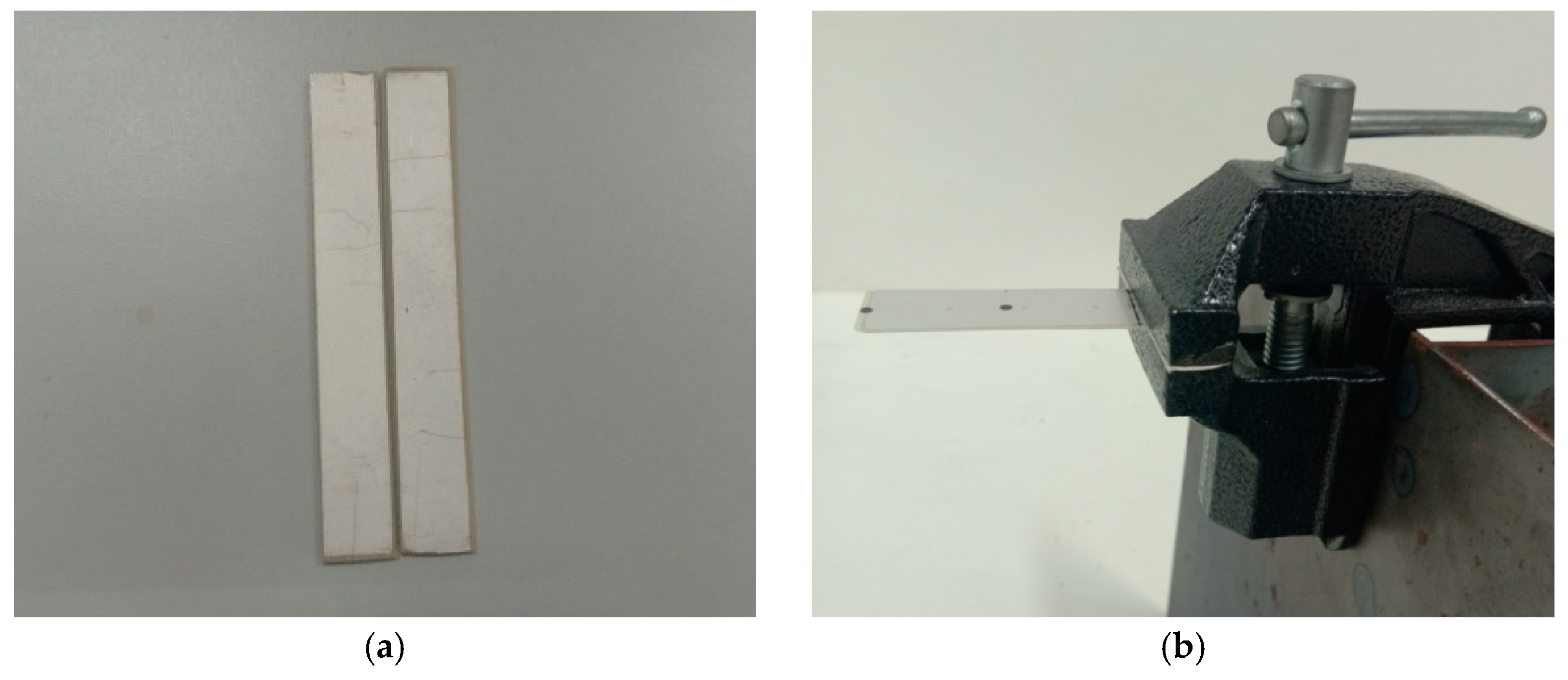
4.1. The Experiments of Piezoelectric Cantilever Beams

In order to further verify the validity of the theoretical solution obtained in this paper, we carried out the related experiments of the free damping vibration of the piezoelectric cantilever beams. The experimental specimens used in this experiment are a PbZrTiO3-5 (generally abbreviated as PZT-5) piezoelectric ceramic sheet with a size of 60 mm × 20 mm × 0.1 mm, and a density of 7500 kg·m3, as shown in Figure 2a. Its physical constants are shown in Table 1. The experimental specimen is fixed and clamped by pliers and supporting devices, and the clamping length is 10 mm, that is, the effective length of the piezoelectric cantilever beam is 50 mm, as shown in Figure 2b. The time–displacement curves of the piezoelectric cantilever beam are measured by a non-contact laser displacement sensor (from ZSY Group Ltd., London, UK), as shown in Figure 3a. The overall measuring device is shown in Figure 3b.
After the experiment device was assembled, loads of 5, 10, and 20 g were applied to the cantilever end of the piezoelectric cantilever beam, respectively. The corresponding displacements of the cantilever end under three levels of load were 0.475, 0.750, and 1.342 mm, respectively. Then, the instantaneous unloading was performed to cause the piezoelectric cantilever beam to generate free vibration under the drive of the initial displacement of the cantilever end. The time–displacement curves of the piezoelectric cantilever beam under these three initial displacements were recorded by a non-contact laser displacement sensor.

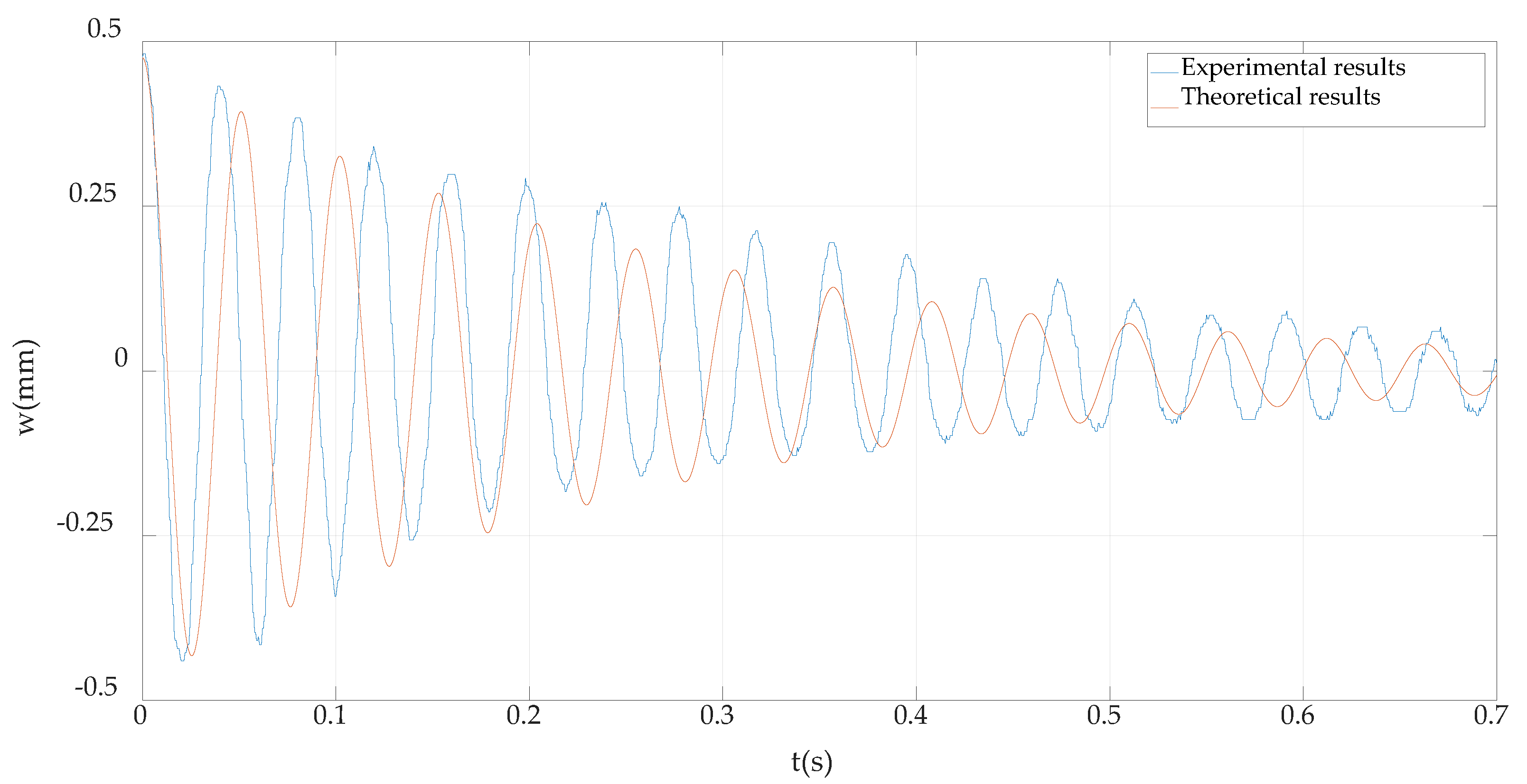
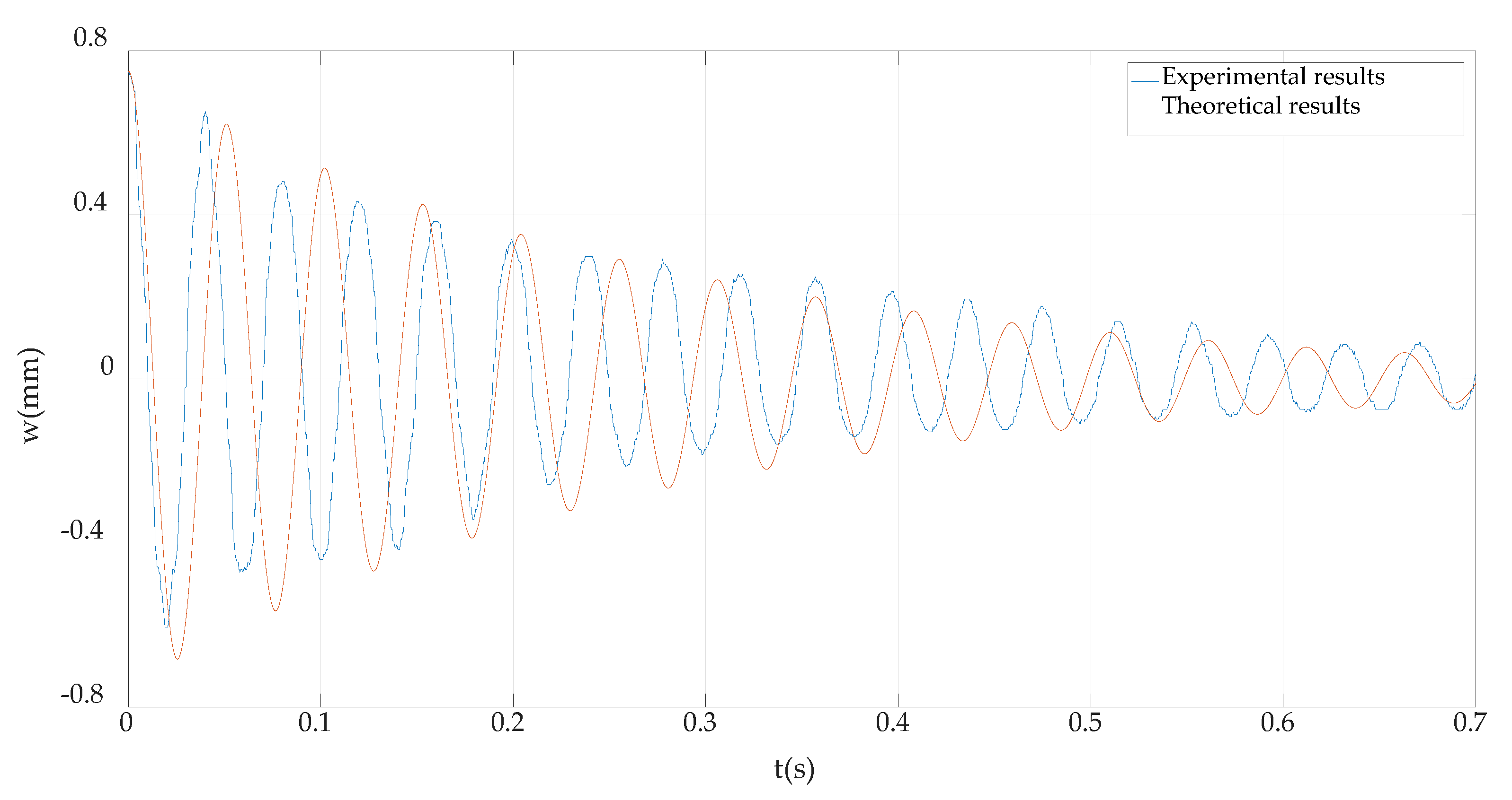
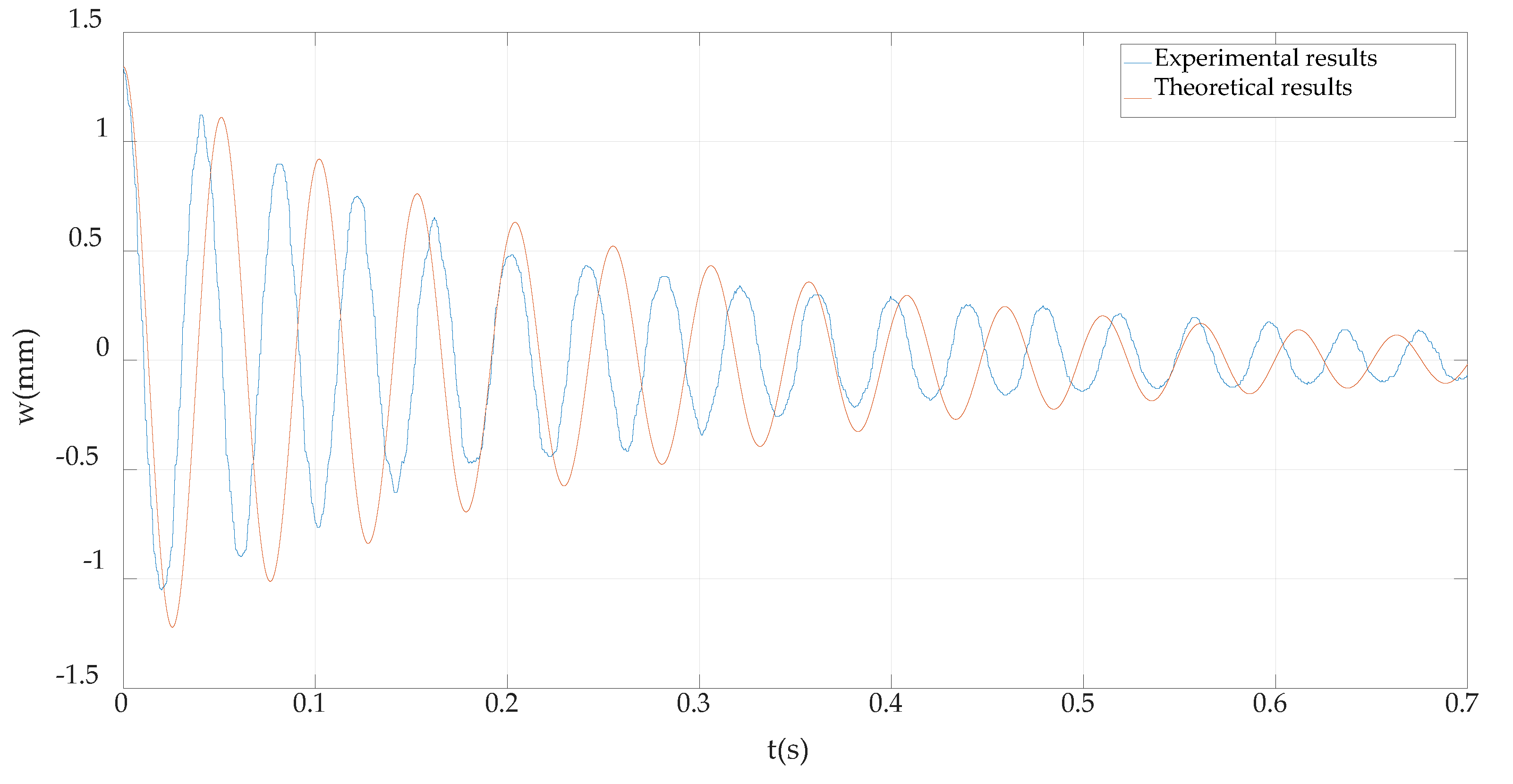
4.2. Comparison of the Experimental Results and Theoretical Results

The time–displacement curves and the vibration frequency of the piezoelectric cantilever beam can be obtained by the above-mentioned experiments. In the following, we compared the experimental results with the theoretical results. Before the comparison, we needed calculate the time–displacement curves of the theoretical solution under three initial displacements, namely, l = 0.05 m, b = 0.02 m, h = 0.0001 m, ξ = 0.03 , and m ¯ = 0.015 kg/m. Thus, from Equations (55) and (56), the vibration frequency and the time–displacement curves can be obtained, as shown in Table 2 and Figure 4, Figure 5 and Figure 6.
As can be seen from Table 2, the errors between the vibration frequency measured by the experiments and the vibration frequency calculated by the theoretical solution are all below 20%, within the range of allowable error. This indicates that the given vibration frequency expression is correct.
From Figure 4, Figure 5 and Figure 6, it can be seen that the differences between the maximum amplitudes of each vibration period obtained by the experiment and the theory are all small, but there is a certain difference in the vibration phase. The main reason for the difference of the vibration phase is that the vibration frequencies obtained by the experiment and theory are not completely equal. In Table 2, the relative errors of the vibration frequencies obtained by the experiment and the theory have been given, and they are within the allowable range. So, it can be said that the experimental results are in good agreement with the theoretical results. This shows that the theoretical solution given in this paper is correct. On the other hand, it also shows that the biparametric perturbation method used in this paper is effective.

5. Concluding Remarks

In this paper, the free damping vibration problem of piezoelectric cantilever beams was solved using the biparametric perturbation method, and its theoretical solution was obtained. In addition, the related experiments were carried out, and the experimental results were compared with the theoretical results. The following main conclusions can be drawn.
(i)
The theoretical solution given in this paper can be degraded to the existing vibration solution of the general cantilever beam, and the theoretical results are in good agreement with the experimental results. These indicate that the analytical solution given in this paper is correct, and the biparametric perturbation method used in this paper is effective.
(ii)
From Equation (11), it can be seen that the piezoelectric properties of the piezoelectric materials will increase the elastic modulus, which is usually known as the piezoelectric stiffening effect peculiar to piezoelectric materials and structures. As we all know, the greater the elastic modulus, the higher the vibration frequency. Thus, the piezoelectric properties will increase the vibration frequency of the piezoelectric cantilever beams.
(iii)
From the perturbation expansion, it is easy to find that the zero-order solution is the solution of the free vibration of the classical cantilever beam, without the piezoelectric properties and damping. The influences of the piezoelectric properties and the damping are reflected in the first-order and second-order perturbation solutions. The analytical characteristic and structural form of the perturbation solution are beneficial to the parameter analyses of the studied problem.
The method proposed in this study may be extended to multi-physical fields like electric, magnetic, or thermal fields, in addition to the traditional mechanical field, and these electric, magnetic, or thermal parameters may be selected as the perturbation parameters. Therefore, the biparametric perturbation, even the multi-parametric perturbation, method, especially based on perturbation parameters with certain physical meanings, agree with, to a certain extent, the basic idea of homogenization. Moreover, the analytical results proposed in this study can provide a theoretical basis and reference for the analysis and design of sensors and actuators based on the piezoelectric effect.

Author Contributions

Conceptualization, X.-T.H. and J.-Y.S.; funding acquisition, X.-T.H. and J.-Y.S.; methodology, X.-T.H. and Z.-X.Y.; data curation, Z.-X.Y. and D.-D.P.; writing (original draft preparation), X.-T.H. and Z.-X.Y.; writing (review and editing), D.-D.P. and J.-Y.S. All authors have read and agreed to the published version of the manuscript.

Funding

This project is supported by the National Natural Science Foundation of China (grant no. 11572061 and 11772072).

Conflicts of Interest

The authors declare no conflict of interest.

References

  1. Holeczek, K.; Starke, E.; Winkler, A.; Dannemann, M.; Modler, N. Numerical and experimental characterization of fiber-reinforced thermoplastic composite structures with embedded piezoelectric sensor-actuator arrays for ultrasonic applications. Appl. Sci. 2016, 6, 55. [Google Scholar] [CrossRef] [Green Version]
  2. D’Annibale, F.; Rosi, G.; Luongo, A. Piezoelectric control of Hopf bifurcations: A non-linear discrete case study. Int. J. Non-Linear Mech. 2016, 80, 160–169. [Google Scholar] [CrossRef]
  3. Dell’lsola, F.; Maurini, C.; Porfiri, M. Passive damping of beam vibrations through distributed electric networks and piezoelectric transducers: Prototype design and experimental validation. Smart Mater. Struct. 2004, 13, 299–308. [Google Scholar] [CrossRef] [Green Version]
  4. Yang, J.; Zhang, Q.; Xu, T. A novel piezoelectric ceramic actuator with scissoring composite vibration for medical applications. Appl. Sci. 2019, 9, 4637. [Google Scholar] [CrossRef] [Green Version]
  5. Mohammed, A.A.; Haris, S.M.; Nuawi, M.Z. Role of piezoelectric elements in finding the mechanical properties of solid industrial materials. Appl. Sci. 2018, 8, 1737. [Google Scholar] [CrossRef] [Green Version]
  6. Mahinzare, M.; Ranjbarpur, H.; Ghadiri, M. Free vibration analysis of a rotary smart two directional functionally graded piezoelectric material in axial symmetry circular nanoplate. Mech. Syst. Signal Process. 2018, 100, 188–207. [Google Scholar] [CrossRef]
  7. Przybylski, J.; Gasiorski, G. Nonlinear vibrations of elastic beam with piezoelectric actuators. J. Sound Vib. 2018, 437, 150–165. [Google Scholar] [CrossRef]
  8. Liu, X.; Wang, J.; Li, W. Dynamic analytical solution of a piezoelectric stack utilized in an actuator and a generator. Appl. Sci. 2018, 8, 1779. [Google Scholar] [CrossRef] [Green Version]
  9. Parashar, S.K.; Wagner, U.V.; Hagedorn, P. Nonlinear shear-induced flexural vibrations of piezoceramic actuators: Experiments and modeling. J. Sound Vib. 2005, 285, 989–1014. [Google Scholar] [CrossRef]
  10. Mukherjee, A.; Chaudhuri, A.S. Nonlinear dynamic response of piezolaminated smart beams. Comput. Struct. 2005, 83, 1298–1304. [Google Scholar] [CrossRef]
  11. Chen, M.F.; Chen, H.L.; Ma, X.L.; Jin, G.Y.; Ye, T.G.; Zhang, Y.T.; Liu, Z.G. The isogeometric free vibration and transient response of functionally graded piezoelectric curved beam with elastic restraints. Results Phys. 2018, 11, 712–725. [Google Scholar] [CrossRef]
  12. Dong, X.J.; Meng, G.; Li, H.G. Free vibration of stepped composite Timoshenko beam with piezoelectric materials. J. Vib. Eng. 2005, 18, 243–247. [Google Scholar]
  13. Li, S.R.; Su, H.D.; Cheng, C.J. Free Vibration of Functionally Graded Material Beams with Surface-Bonded Piezoelectric Layers in Thermal Environment. Appl. Math. Mech. 2009, 30, 907–918. [Google Scholar] [CrossRef]
  14. Oh, I.K.; Han, J.H.; Lee, I. Postbuckling and vibration characteristics of piezolaminated composite plate subject to thermo-piezoelectric loads. J. Sound Vib. 2000, 233, 19–40. [Google Scholar] [CrossRef]
  15. Li, Y.; Shi, Z.F. A new method for free vibration analysis of piezoelectric-elastic laminated beams. Chin. J. Theor. Appl. Mech. 2008, 40, 564–571. [Google Scholar]
  16. Lu, Y.T.; He, B.W.; Guan, Q. Exact solution of dynamic for piezoelectric laminated beams. J. Anhui Jianzhu Univ. 2015, 23, 79–93. [Google Scholar]
  17. Chen, W.Q.; Lv, C.F.; Bian, Z.G. Free vibration analysis of generally laminated beams via state-space-based differential quadrature. Compos. Struct. 2004, 63, 417–425. [Google Scholar] [CrossRef]
  18. Kapuria, S.; Alam, N. Efficient layerwise finite element model for dynamic analysis of laminated piezoelectric beams. Comput. Methods Appl. Mech. Eng. 2006, 195, 2742–2760. [Google Scholar] [CrossRef]
  19. Chen, S.L.; Li, Q.Z. The FPPM solutions for the problems of large deflection of axisymmetric circular plate. J. Chongqing Jianzhu Univ. 2003, 25, 32–36. [Google Scholar]
  20. Lian, Y.S.; He, X.T.; Liu, G.H.; Sun, J.Y.; Zheng, Z.L. Application of perturbation idea to well-known Hencky problem: A perturbation solution without small-rotation-angle assumption. Mech. Res. Commun. 2017, 83, 32–46. [Google Scholar] [CrossRef]
  21. Nowinski, J.L.; Ismail, I.A. Application of a multi-parameter perturbation method to elastostatics. J. Theor. Appl. Mech. 1965, 2, 35–45. [Google Scholar]
  22. Chien, W.Z. Second order approximation solution of nonlinear large deflection problem of Yongjiang Railway Bridge in Ningbo. Appl. Math. Mech. 2002, 23, 493–506. [Google Scholar]
  23. He, X.T.; Chen, S.L. Biparametric perturbation solutions of the large deflection problem of cantilever beams. Appl. Math. Mech. 2006, 27, 404–410. [Google Scholar] [CrossRef]
  24. He, X.T.; Cao, L.; Li, Z.Y.; Hu, X.J.; Sun, J.Y. Nonlinear large deflection problems of beams with gradient: A biparametric perturbation method. Appl. Math. Comput. 2013, 219, 7493–7513. [Google Scholar] [CrossRef]
  25. He, X.T.; Cao, L.; Sun, J.Y.; Zheng, Z.L. Application of a biparametric perturbation method to large-deflection circular plate problems with a bimodular effect under combined loads. J. Math. Anal. Appl. 2014, 420, 48–65. [Google Scholar] [CrossRef]
  26. Clough, R.W.; Penzien, J. Dynamics of Structures; Wang, G.Y., Translator; China Science Publishing House: Beijing, China, 1981. [Google Scholar]
  27. Ruan, X.P.; Danforth, S.C.; Safari, A.; Chou, T.W. Saint-Venant end effects in piezoceramic materials. Int. J. Solids Struct. 2000, 37, 2625–2637. [Google Scholar] [CrossRef]
Figure 1. Scheme of the mechanical model of the piezoelectric cantilever beam.
Applsci 10 00215 g001
Figure 2. Scheme of the experimental specimens and piezoelectric cantilever beam: (a) PZT-5 piezoelectric ceramic specimens; (b) the piezoelectric cantilever beam.
Applsci 10 00215 g002
Figure 3. Scheme of the measuring instruments and experimental device: (a) the non-contact laser displacement sensor; (b) the integral measuring device.
Applsci 10 00215 g003
Figure 4. The time–displacement curves under the initial displacement of 0.475 mm.
Applsci 10 00215 g004
Figure 5. The time–displacement curves under the initial displacement of 0.750 mm.
Applsci 10 00215 g005
Figure 6. The time–displacement curves under the initial displacement of 1.342 mm.
Applsci 10 00215 g006
Table 1. Physical properties of the PZT-5 materials [27].
Elastic Constant (10−12 m2·N−1)Piezoelectric Constant (10−12 C·N−1)Dielectric Constant (10−8 F·m−1)
s11s12s13s33s44d31d33d15λ11λ33
16.4−5.74−7.2218.847.5−1723745841.5051.531
Table 2. Frequency comparison of the experimental results and theoretical results.
Initial Displacements (mm)Vibration Frequency
Experimental Results (rad/s)Theoretical Results (rad/s)Relative Errors (%)
0.475123.25146.1215.65
0.750123.25151.4018.59
1.342123.25139.6311.01

