Abstract
In this study, the optical sphere and the power analyzer were exploited to measure the optical and power parameters for the high-power LED lamps. The results, derived from the experimental data, were used as the power distribution inputs in the finite element analysis (FEA) for the determination of the temperature distribution for the printed circuit board assembly (PCBA) built in the LED lamp. In the finite element analysis, the conjugate heat transfer model was adapted for the calculation of the heat transfer, including thermal conductivity, convection and radiation. Applied on the power chips located on the PCBA, the graphene thermal interface material (TIMs) had been studied for its effects on the temperature distribution. For an accurate simulation about the LED lamp, the model with closed and compact space was built in the analysis. Compared to the experimental data, it showed that the simulation results had a deviation in the range of 3–5% around the main heating source, the light-emitting diodes. It proves the FEA model proposed in this study were well developed for the simulation of the temperature distribution for the high-power LED lamps which have mixed heat transfer mechanisms. The thermal radiation effects by TIMs with graphene were also investigated in this study and proven to be useful for the heat dissipation for the LED lamps.
1. Introduction
High thermal resistance for printed circuit board assembly (PCBAs) will decrease the heat transfer efficiency, and the performance reduction is inevitable for the power chips on PCBAs, due to the over-heat problem. Conventionally, filling the gap between the chips and the board with thermal grease or thermal Interface materials (TIMs), it is expected that the capability of thermal conductivity will be increased to overcome the overheating problem for the power chips on the PCBA. Taking light-emitting diode (LED) lights as an example, LED lights have excellent luminous efficacy and energy-saving features, as compared to those of the traditional bulbs. In industry, high brightness and illuminance is achieved by multiple LED arrays. In the case of single LED light chip, the input voltage will be raised to qualify the requirements for brightness and illuminance. No matter what the solution is, using LED chip arrays or raising the input voltage, a non-uniform and over-heating temperature distribution is often observed for the PCBAs inside the LED lamps. The corresponding result is the performance and working life reductions for LED lights. Another similar case is the electronic virtual reality devices (VR). Due to the huge and fast operations for image processing, VR devices have several high-power chips which are considered as heat sources on the PCBA. As the power input is high and the volume of the VR device is small, cooling the power chips will be very difficult. Obviously, the traditional TIMs or grease is not enough for the cooling requirements for the up-to-date electronic devices. There should be new heat sinkers or dissipators which are able to solve the over-heat problems for the powerful and compact electronic devices.
In this study, the conjugate heat transfer model provided by the commercial finite volume method (FVM) software, FLUENT, will be used for the analysis about the temperature distribution for the electronic devices with high-power chips and compact volumes, such as LEDs and VRs. The values of power for the dominant chips on the PCBA will be derived experimentally by the optical sphere and the power analyzer. In the FEA model, the power chips will be simulated as heat sources. Heat by conduction will pass through the printed circuit board from the power chips. On the boundary between the PCBA and air, heat transfer by convection will happen. In addition, when the power chips are applied with TIMs of graphene, the heat transfer by radiation will be introduced in the analytic model. Finite space will be constructed to simulate the cases for LED lights. The results of simulation will be verified by those data obtained by the experiments, which confirms the validity of the proposed FEA model.
2. Literature Review
The parameters for the design of LED lights include luminous flux, chip temperature, input power and cooling mechanism, etc. An excessively high operating temperature will decrease the performance of LEDs. Generally, the higher the luminous flux is, the higher the operational temperature is. Precise measurements are thus very important for the verification of LED lights’ performance. It was pointed out that the factors such as heat flux intensity, interference by heat flux, forward voltage, must be carefully handled for an accurate measurement of LED lights [1]. In 2017, Chernyakov analyzed the temperature distribution for different arrays of AlInGaN LEDs. With the physical model developed for the LED array, Chernyakov built an expression for the thermal resistance. Using optical microscopy and a thermographic camera, the relationship between thermal resistance and current was established by Chernyakov, and the actual temperature distribution was then obtained for the LED array [2]. Studies showed that the current density on the surface of the chip is critical for the performance of LEDs. According to a study by Cheng Qian, when the current density is controlled to be uniform, an extra 8% of luminous flux can be achieved [3]. As the size of the chips is gradually miniaturized, the heat density of the LEDs is accordingly increased. Thus, it is important for the trend of miniaturization for LEDs that the reliability and service life can be accurately predicted by the corresponding measurement and/or analysis. The topics of studies about LED lights include LED long-term reliability analysis, real-time temperature monitoring, measurement of their mechanical properties at high temperatures, and performance estimation of LEDs through TIMs temperature monitoring [4,5]. Nowadays, the heat dissipation methods for the electronic components and LEDs in the industry are divided into two major parts: active heat dissipation and passive heat dissipation. Excellent heat dissipation means the high-quality performance of LEDs. However, the operation for measuring the performance of LEDs is complex and very time consuming. Instead of practical measurements, many studies have approached the study of LEDs by simulation. For example, Kudsieh used ANSYS-13TMFFM to investigate chip-on-plate LEDs for solid state lighting and backlight displays. The results showed that a rectangular substrate has an effective thermal diffusion and uniform temperature distribution as compared to the circular and irregular substrates [6].
Sealed in a close and compact housing, the PCBAs of the modern electronic devices often suffer from overheating problems. In the housing, high heat conduction efficiency is necessary for producing a uniform temperature distribution over the PCBA. However, the little space between the PCBA and the shielding case will hinder the heat dissipation due to the poor heat convection capability [7,8,9]. New TIMs have been developed for solving the overheating problem, and are used for the up-to-date electronic devices with compact size. TIMs tuned with carbon nanotubes (CNTs) or graphene are proposed for heat dissipation. A study by Zhang demonstrated that the carbon nanotube-thermal interface material (CNT-TIM) reduced the thermal interfacial resistance significantly compared with the state-of-art commercial TIM. The optimized thermal resistance of the CNT arrays is as low as 7 mm2 K W−1. The results indicated that the light output power was greatly improved with the use of the CNT-TIM [10].
In 2004, Geim and Novoselov at the University of Manchester used mechanical exfoliation to separate graphene from layered graphite. It was found that graphene has good mechanical properties which supported its prospective applications in academia and industry [11]. Single-layer graphene is often discussed in a theoretical framework, but in practical applications, multi-layer graphene is mainly used. Multi-layer graphene has about three to 10 layers, and the thickness of each layer is about 0.33 nm. Compared with silver, copper, gold, and aluminum in graphene, graphene has a better thermal conductivity of 5300 W/mK (theoretical value of a single layer). This value is calculated by measuring the Raman peak position change with the laser power and temperature after heating the test piece with a laser [12,13]. Due to the fact the thickness of single-layer graphene is about 0.33 nm, it is mostly used as a thermal interface material as an additive or a thermal interface material made of multilayer graphene by lamination. However, increasing the number of layers of multilayer graphene will decrease its thermal conductivity [14], so it is very important to determine the planar thermal conductivity of thin materials.
In 1994, Chai proposed to use the finite volume method and derive its mathematical calculation formula to solve the heat radiation issue [15]. Due to advances in materials science, many gray-body materials with good radiation coefficients have been developed. In recent years, more and more scholars have used numerical analysis to research thermal radiation. Cheng developed a calculation method for thermal radiation and verified it. This formula can simply consider thermal radiation and can also be used in fluid dynamics analysis software. According to the research, it is found that the division of the center angle at the intersection of the grid will affect the accuracy of numerical simulation [16]. After discussing the meshing, many scholars also compared different thermal radiation calculation formulas. Different thermal radiation modules in common commercial software combined with heat conduction or natural convection coefficients in different environments are experimentally verified to find suitable application for numerical simulation [17,18].
3. Theories and Research Methods
The wattage of LEDs is used for classification in the industry. The LEDs with powers greater than 1 W are called high-power LEDs, medium-power LEDs are in the 0.5~1 W range, and if less than 0.5 W, they are low-power LEDs. When discussing the temperature field of LEDs, the industry mostly uses thermal resistance theory and temperature rise experiments for design purposes. In the academic world, numerical simulation methods are used to investigate the optimal arrangement of single LED modules and multiple LED modules, as well as the research on the heat dissipation effects of heat pipes and fins. These studies only discuss the heat dissipation problem of LED chips in open space. The wattage setting during simulation is relatively simple, only setting the wattage of the LED without discussing the thermal effects caused by the heating circuit components.
Therefore, this study will simulate the heat dissipation in the compact space of commercial high-power LED lighting equipment, and the unfilled LED device will be the main research object. The integrating sphere is used to measure the difference wattage between the controller IC and the circuit without the controller IC in the same lumen, and the finite element method software is used as the numerical calculation software. The thermoelectric module and the fluid module of the finite element method software are used to simulate the influence of temperature field distribution, heat dissipation efficiency and thermal resistance of the LED device under different thermal interface material parameters.
3.1. Basic Theory of LED
LEDs originated in 1907 and were published in a journal by Captain H.J. Round. When Round applied current to silicon carbide crystals (SiC), it caused the crystal to produce a light source. In 1936, the phenomenon in which an electric field was used to excite a material to generate a light source was collectively referred to as electroluminescence. Due to the rapid development of semiconductor technology, p-n junction light-emitting diodes (LEDs) made of semiconductor materials appeared in 1950. An LED is composed of a semiconductor material, and the crystal is divided into a p-structure and an n-structure by implantation or doping techniques, and the structure can form a positive electrode and a negative electrode. The current flows through the p-pole to the n-pole. When the hole meets the electron, the electron will fall to a lower energy level, releasing energy and causing a luminescence phenomenon [19].
LEDs are different in use from conventional polar incandescent lamps, they only emit light when a forward current passes. When the power supply voltage changes slightly, it will cause a large change in the current. Due to the great relationship between the luminosity of the LED and the current change, if the current changes too much, the illuminance of the LED will deviate from the design value. When the design safety value is exceeded, the thermal resistance will increase and the power consumption of the LED will become larger and damage the device. Therefore, commercial LED modules often add IC control components on the circuit board to stabilize the overall LED power consumption [20].
3.2. Heat Transfer Theory
General heat transfer is divided into three mechanisms (Figure 1): heat conduction, heat convection, and heat radiation. In the past, the heat dissipation mechanism from the electronic component to the electronic product stage was mainly based on heat conduction and heat convection. A common cooling method is to install an aluminum fin or heat pipe system on the heating element to increase the heat conduction and heat convection heat transfer area. In recent years, due to developments in materials science, materials with excellent thermal emissivity and good thermal conductivity have been applied, so that the circuit boards of miniaturized electronic products in a narrow space have a new heat dissipation method.
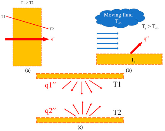
Figure 1.
Heat transfer. (a) Heat conduction. (b) Heat convection. (c) Heat radiation.
3.2.1. Heat Conduction
Heat conduction means that the particles in the part of the material at a higher temperature have more energy and the particles collide with each other frequently, and the energy is transmitted from the high temperature to the low temperature. The transmission media can be divided into fluids, liquids and solids. Fluids and liquids transfer heat due to irregular collisions and diffusion between molecules, and solids transfer heat due to the vibration of molecular and the transmission of free electrons. The equation can be defined by Fourier’s law of heat conduction:
In this equation, is the heat flow rate, and k is the thermal conductivity. When the value of k is larger, the heat conduction is better. is the cross-sectional area of the object.
3.2.2. Heat Convection
Thermal convection is a heat transfer mode between a solid surface and a liquid or gas contact surface. It can be divided into two types, the random movement and diffusion of microscopic fluid molecules, and the macroscopic fluid flow. Therefore, the flow velocity, density, viscosity coefficient, thermal conductivity, flow field direction, and geometry of the fluid all affect the heat transfer rate of the heat convection. This complex heat transfer mechanism can be expressed by Newton’s law of cooling:
In this equation, h is the convective coefficient. Both the coefficient and the thermal conductivity are non-material. It needs to be obtained by experimental or semi-empirical equations, and A is the cross-sectional area of the object. Generally, the larger the area, the better the heat dissipation efficiency. is the difference between the heat source temperature and the ambient temperature. The general convection coefficient can be divided into: natural convection, forced convection, boiling, condensation.
3.2.3. Heat Radiation
Heat radiation generally has its effect in high temperature environments, due to the influence of the radiation emission coefficient of the material. The most ideal radiation emission coefficient is 1 for blackbody radiation. The coefficients of some common heat dissipation materials are 0.02 for aluminum and 0.09 for copper. The material coefficients of these materials are not ideal. When the radiation emission coefficient is relatively low, the radiation heat dissipation must occur at an extremely high temperature. The radiation heat transfer emits thermal energy in the form of electric waves, so there is no need to rely on any medium, and heat can be transferred even in a vacuum environment. The formula of heat radiation is:
where A is the radiation heat-dissipation area, ε is the thermal radiation coefficient value in the range of 0~1, and σ is the Boltzmann constant value 5.6704 × 10⁻⁸ W/m2K4.
3.3. Numerical Simulation Method
The study uses the commercial numerical simulation software ANSYS Workbench, which can handle numerical analyses of heat transfer, rigid plastic, viscoelastic, elastic-plastic, fatigue, damage, creep, flow field and electric field problems. In the advanced multi-physics area, it can deal with linear and nonlinear thermal-structure interaction and fluid-solid interaction. In this study, the module is a thermoelectric module and a Fluent module. In the VR device circuit board simulation, the heat transfer analysis module is mainly used for simulation, and the space is an open environment with natural convection. The LED simulation uses the Fluent module for numerical analysis. The environment is the conjugate heat transfer mode of electronic parts, LED and circuit board in a closed environment. The analysis model is a filled high-power LED work light, because in the unfilled LED, a closed gas environment will be generated in the PC material lamp cover and PCBA, in which the gas will change in density as the temperature rised and form a natural convection in a closed environment. However, after a period of heat balance, a stable temperature will be formed between the air temperatures, and the heat transfer efficiency will also decrease. This hypothesis space is shown in Figure 2. Therefore, in order to establish a set of analysis modes for radiating heat in a hermetic space, the model will assume a hermetic space to investigate the heat transfer effects of radiative heat dissipation and thermal interface materials.
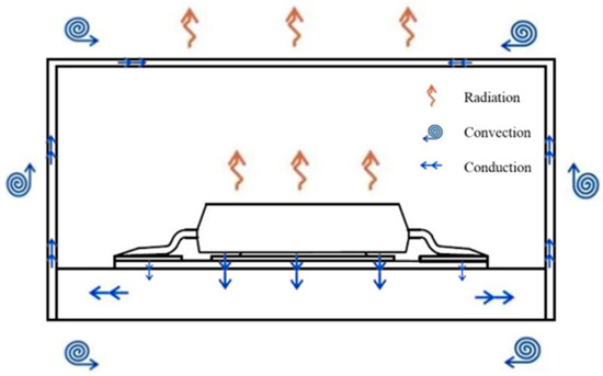
Figure 2.
LED enclosed compact space schematic.
The numerical simulation of this study is roughly divided into three parts: pre-processing, numerical calculation and post-processing. Pre-processing uses the Workbench generic module for model processing. The main work is to build models and finite element meshing. The material properties, boundary conditions and environmental conditions were established and analyzed using Fluent modules and heat transfer modules for numerical calculations. The calculation uses the heat transfer theory and the momentum, flow, and radiation theoretical formulas in Fluent to solve the problem. Post-processing is the process of exporting the results of numerical operations into contour maps and converting them into data and graphical data.
3.3.1. Meshing
Meshing is an important part of numerical simulation. This stage is related to the accuracy and operation time of the analysis results. However, before meshing, the Design Modeler module in ANSYS Workbench is used to perform Boolean operations on each area of the geometric model to avoid excessive quality or interference of the mesh between the models, resulting in excessive errors or even failures. In ANSYS Mesh, the number of structured meshes is defined as the same number of adjacent meshes for all mesh nodes in the region. The grid is usually a hexahedron or a quadrilateral. Their advantage is that the meshing speed is faster and the quality is relatively good, which also makes the data structure simpler and faster, but it is more difficult to generate mesh when dividing the complex structure. Therefore, when the complex model is meshed, it will be divided by tetrahedron and triangle. The advantage is that the division can be easily generated on any model, but the convergence and accuracy are slightly inferior to the hexahedron and quadrilateral mesh. Figure 3 shows the different types of mesh.
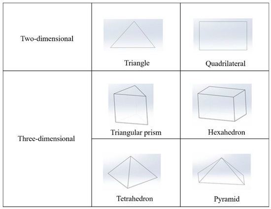
Figure 3.
Element type.
In Fluent, the pressure solution is used to solve the variation of each governing equation sequentially. However, the simulation projects of the governing equations are mostly nonlinear or coupled, so it is necessary to obtain numerical solutions by iteration. Each iterative solution needs to update the material properties first, and use the variable pressure and mass flux to solve the momentum equation and the pressure correction equation, calculate the mass flux, pressure, velocity, and then calculate the governing equations such as turbulence, radiation and energy.
3.3.2. Finite Volume Method
In this study, the commercial software FLUENT will be used for the analysis of the temperature distribution. In fluid dynamics, it is calculated by the finite volume method. The discretization technique divides the analysis target area into several control volumes. The control volume after the division is completed will have a main node. Therefore, in the numerical analysis, all control volumes must be integrated into various different forms of the governing equations, and then the discrete equations are derived by corresponding initial values and boundary conditions on the nodes.
There are two kinds of solvers in the calculation, namely Pressure-Based Solver and Density-Based Solver. The density solution is solved simultaneously by coupling and discrete equations, and all variables are solved in parallel. The solution of pressure is to solve the variables of the governing equations in order, but the governing equations are mostly nonlinear or coupled, so it is necessary to carry out the iteration to obtain the numerical solution. The solver step are as follows:
- (1)
- Set the initial variable values (temperature, pressure, flow rate).
- (2)
- Solve discrete equations such as energy, continuity, and momentum.
- (3)
- Solve the turbulence and radiation equations.
- (4)
- Determine whether the calculation step is converged. If it cannot converge, return to the second step for the iteration operation. If convergence occurred, proceed to the next calculation.
3.3.3. Relaxation Factor
The equations solved by fluid dynamics are mostly coupled and nonlinear, so it is very important to control the variation of variables during the solution process. Therefore, the change of the calculation variable generated by the iteration is adjusted by the Relaxation Factor, and the operation value plus the relaxation factor is multiplied by the variable to obtain a new value. As shown below:
In this formula:
- Qnew = new value for iteration
- Qold = old value of iteration
- = relaxation factor
- = calculation variable
The relaxation factor can control and improve the convergence speed and accuracy. When the value is greater than 1, the convergence can be accelerated. If less than 1, the convergence can be improved and the iteration difference can be prevented from being too large and divergent.
3.4. Numerical Simulation Theory
3.4.1. Fluid Dynamics Theory
The numerical simulation of the temperature field of the LED module in a tightly closed space is carried out, and the problem of heat transfer between the gas and the solid in a hermetic space must be considered. The heat transfer mode is called conjugate heat transfer. Therefore, the study uses the Fluent module in ANSYS Workbench for numerical simulation of the LED temperature field. In today’s fluid analysis, most of the Finite Volume Method is used to solve the problem. The finite volume method is to divide the volume of the simulated object and generate nodes in the volume. The boundary conditions set in the numerical simulation are used to integrate the governing equations and discretize them to solve the numerical results. The governing equations used in the study include discrete equations such as continuous, momentum, and energy equations, and equations such as turbulence and radiation are added.
Proposed by Fluent, there are five calculation models for the radiation module:
- (1)
- Discrete Ordinates Model (DO)
- (2)
- Discrete Transfer Radiation Model (DTRM)
- (3)
- P1 Radiation Model (P1)
- (4)
- Rosseland Model
- (5)
- Surface-to-surface (S2S)
The Discrete Transfer Radiation Model’s computational model is relatively simple, and one can increase the numerical accuracy by increasing the number of rays during the calculation. However, all the faces of the model are diffuse reflections, which also causes the reflection of the radiation to be more complicated than the incidence, and also causes the CPU’s resource consumption to increase relatively when solving a large number of rays. The P1 Radiation Model consumes less computational resources than DTRM when calculating thermal radiation conduction. It is relatively stable when considering large optical depths, such as high-temperature combustion models, but it magnifies radiation transmission when computing local heat sources and heat sinks. Surface-to-surface is ideal for solving problems in a closed space without the medium transmitting radiation, but not for the thermal radiation problems that the medium is involved in. The Discrete Ordinates Model (DO) mode is applicable to all wavelength range radiation problems in analysis and can analyze Surface-to-surface (S2S) problems without medium participation and can also solve the problem of heat radiation transmission involving medium, so it will take longer in the numerical solution time.
When the radiation reaches the same order of heat convection and heat conduction or significant heat transfer occurs, the effect of heat radiation must be considered. When considering radiative heat transfer, attention must be paid to the radiation intensity, I(r,s) in the radiation transfer equation has directionality and spatiality. When radiative heat transfer, the radiation intensity has the following mechanism:
- (1)
- Local absorption
- (2)
- Out-scattering
- (3)
- Local emission
- (4)
- In-scattering
The radiation equation used in this study is the DO Equation module. The DO module is suitable for radiation problems in various optical depth ranges. This module can solve the radiation problem of the S2S non-medium closed region and can also solve the model with medium participation. The numerical theory equation derivation of DO Equation is performed below:
where
| = Gas absorption coefficient | = Gas local temperature |
| = Gas scattering coefficient | = Boltzmann constant (5.6704 × 10⁻⁸ W/m2K4) |
| = Emission intensity | = Phase function |
| = Position vector | = Solid angle |
| = Direction vector | = Wavelength |
| = Scattering direction vector |
3.4.2. Heat Transfer
There are two types of thermal analysis modules for solid heat transfer, which are steady-state heat transfer and transient heat transfer. When the net heat flow rate of the system is zero, the heat flowing into the system and the heat generated by the system itself are equivalent to the heat flowing out of the system, called steady-state heat transfer. Transient heat transfer is the process of heating and cooling the system. During this process, the temperature, heat flow rate, thermal boundary conditions, and internal energy of the system will change with time. Of course, the radiant heat transfer in heat transfer is a nonlinear thermal analysis, so the heat transfer theory of these three numerical simulations will be deduced below.
The temperature of any node on the steady-state heat transfer system does not change with time, so the steady-state heat transfer energy balance equation (represented in matrix form) can be:
where: K(T) = Conduction matrix and {T} = Node temperature vector
For transient heat transfer, according to the law of conservation of energy, the transient thermal equilibrium can be expressed as (in matrix):
where: [C] = Specific heat matrix and {} = Time derivative of temperature.
For nonlinear heat transfer, when the thermal properties and boundary conditions of a material change with time, or contain nonlinear elements, considering radiant heat transfer, it is defined as nonlinear heat transfer, and its equation is:
where: = Specific heat time matrix and = Natural convection matrix
4. Results and Discussion
4.1. Experimental Process
The most important parameters of the printed circuit board assembly (PCBA) and the light-emitting diode (LED) during the simulation are the voltage and current during operation, and the wattage is obtained. However, commercial products will add IC chips that control the switch to the circuit to protect the circuit and the LED from excessive temperature and cause a decrease in light intensity. In the past, the commercial LED model simulated in the study simply set the wattage for the entire board or ignored the electronic chip, control IC and electronic parts. Therefore, this study uses a real case to establish a more accurate numerical simulation method. Before the simulation, the integrating sphere and circuit measurement are performed for LED and PCBA to obtain the parameters required for the simulation. In this experiment, the original LED module is first measured with the integrating sphere for light intensity, and the power supply is used to provide a fixed voltage, and then the current is slowly adjusted to the desired value within a fixed time, and then monitored until the light intensity tends to stable. Through this experiment, the total wattage of the LED and PCBA corresponding to the light intensity value of the LED module can be obtained, but this value still cannot correctly set the wattage of each part during the numerical simulation. Therefore, through the circuit diagram, it can be judged that the conventional positive electrode pad is heated by the forward voltage, and there are two ICs that mainly generate heat on the circuit board. In order to obtain the wattage of the two ICs and the four LEDs, skip the two ICs on the board, re-weld the positive and negative power lines, and drive the LEDs for light intensity measurement, the target is that it can be the same as the light intensity value of one experiment. When the values are the same, the obtained voltage is multiplied by the current, which is the wattage of the four LEDs. The total wattage of one experiment is subtracted from the wattage of the LED to obtain the wattage of the two ICs. The information provided in the IC manual is used and calculated to get the IC wattage. After the parameters are obtained, the ANSYS analysis software is used for numerical simulation. During the period, the temperature field of the LED is measured by using thermoelectric coupling and infrared thermal display. Finally, the numerical simulation results are confirmed by the experimental temperature field.
4.2. TIMs Thermal Conductivity Measurement
The thermal interface materials used in this study are PH3-thermal composite materials, T62-natural graphite and T68-artificial graphite produced by T-Global Technology [21]. Since the thermal radiation effect is explored through simulation in the study, the main researched thermal interface materials will be based on commercially available graphene thermal interface materials, and the models are MSBX0001, MSX0095, MSA3050, and MSA13050. The MSX series consists of a simple graphene stack, while the MSA series adds aluminum to the bottom of the graphene. In the numerical simulation of the temperature field, the thermal conductivity of the material is a very important parameter. The thermal conductivity of the thin material is measured by the HOT DISK instrument, and the numerical value of the study is confirmed.
According to the HOT DISK measurement results, the measured thermal conductivity is lower than the thermal conductivity coefficient provided by the manufacturer. The average measured thermal conductivity of the thermal interface materials of MSBX001 and MSBX0095 pure graphene is 4.2 W/mK and 3.6 W/mK. The trend is in line with the material properties of graphene with a decrease in thermal conductivity when the number of stacked layers is increased. In the graphene thermal interface material made of aluminum substrate, the average value of MSA3050 is 163.5 W/mK, and the average value of MSA13050 is 225.4 W/mK. It was found that the heat transfer coefficient of the aluminum-based graphene thermal interface material increases with the thickness of the aluminum substrate. Model MSA13050 has a graphene thickness of 50 microns. In general, the thermal conductivity of aluminum is 237 W/mK, which is between 25 μm of MSBX001 and 95 μm of MSBX0095. Therefore, it can be judged that the measured value of the graphene interface material having an aluminum substrate is mostly affected by the heat transfer coefficient of the aluminum material. When a commercially available graphene thermal interface material is used, since the graphene heat transfer coefficient measured by the micro-environment in the nanometer-scale environment is based on the industry, actual measurement should be performed before the research or use to obtain the correct parameters.
4.3. LED Temperature Field Measurement
After the simulation method is established, the effect of thermal radiation in a compact space will be simulated. The graphene thermal interface material has a high thermal emissivity for heat radiation dissipation of the LED module. In the graphene thermal interface material, there are different thicknesses of pure graphene interface and interface materials made of different aluminum substrate thicknesses, so the heat dissipation efficiency under different parameters can be compared. The 24, 48, 60 V driven LED is supplied with current at a constant voltage. The position of the measuring point is shown in Figure 4. The temperature measurement of the four LEDs is carried out, numbered from 1 to 4, while the points 5 and 6 are the positions of the two control ICs. Point 11 is the temperature of the positive tin solder joint. This point will increase the temperature with time due to the impedance, which will affect the temperature field of the enclosed space, which should not be ignored. Points 7 to 10 are the positions of the heat sink fins corresponding to the light emitting diodes.
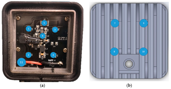
Figure 4.
Position of thermoelectric coupling measurement points. (a) LED thermocouple measurement points (front). (b) LED thermocouple measurement points (back).
The measurement results of 48 V are shown in Figure 5. The measurement results of 60 V are shown in Figure 6. It is found by experiment that the light-emitting diode is located above the points 1 and 3, but their temperatures are lower than the points 2 and 4, about 6 °C to 7 °C. Therefore, it is judged by the experimental operation that when the thermoelectric coupling is adhered to the measuring point, some micro-pores are exposed above the PC cover, resulting in a relatively low temperature of the upper thermal field, and the temperature field of the external heat-dissipating fins may be unevenly distributed.
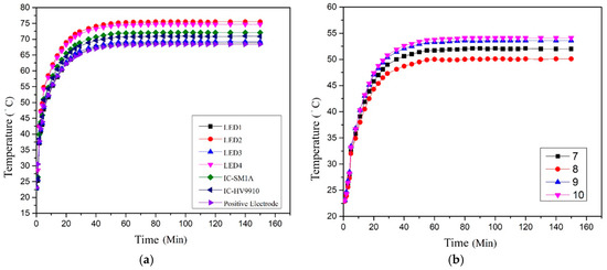
Figure 5.
Temperature measurement of 48 V/ 0.15 A LED. (a) LED internal temperature field. (b) Aluminum fin temperature field.
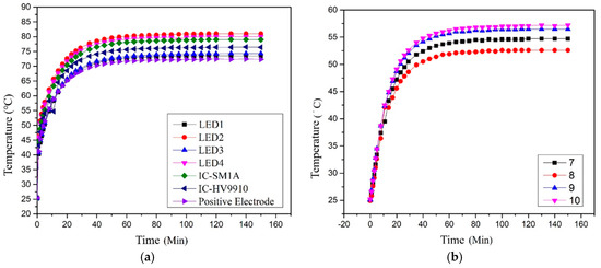
Figure 6.
Temperature measurement of 60 V/0.15 A LED. (a) LED internal temperature field. (b) Aluminum fin temperature field.
4.4. Mesh Convergence Analysis
Before starting the simulation, a mesh convergence analysis must be performed to justify the particular mesh used for the simulation. The mesh and convergence analysis result of the single chip model are shown in Figure 7, although the maximum temperature has converged at number of elements of 1580, for more accurate results, the mesh of 15751 elements is used in the simulation. The mesh and convergence analysis result of the PCBA model are shown in Figure 8, when the number of elements is 13,448, the maximum temperature results reach convergence, therefore the mesh of 13,448 elements is used in the simulation.
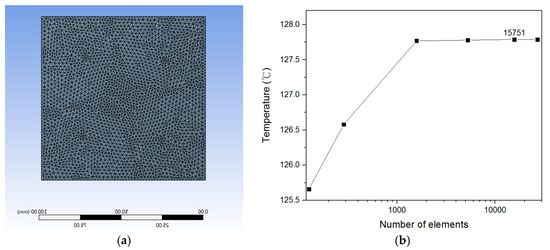
Figure 7.
Mesh of single chip model. (a) Mesh. (b) Mesh convergence analysis.
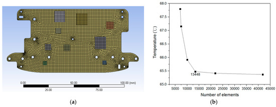
Figure 8.
Mesh of PCBA model. (a) Mesh. (b) Mesh convergence analysis.
4.5. Comparison of Heat Dissipation of Single Chip
Before performing the VR board simulation and LED compact space simulation, it is necessary to confirm whether the mode and parameters are correct. Especially when graphene and its composite heat sink are measured by HOT DISK, the heat transfer coefficient is slightly different from that provided by the literature and the manufacturer. Therefore, the preliminary thermoelectric simulation was established through a single chip heat dissipation experiment, and the simulation results of the heat transfer coefficient measured by HOT DISK, the data provided by manufacturer and the literature parameters were compared.
In the experiment, a 2 W power-heated chip was placed in an open space, and the MSA13050 was attached underneath. In heat transfer simulation, the heat transfer coefficient of 1600 W/mK and the measured value of 235.5 W/mK measured by HOT DISK is set on the XZ plane, and the vertical direction Y is set to 3 W/mK and the natural convection coefficient is 12.5 W/m2K. The experimental results are shown in Figure 9. The maximum temperature is 98.5 °C when the chip is not using any heat-dissipating patch, and the highest temperature is 54.6 °C when the MSA13050 graphene composite is pasted to the bottom chip. The original single-chip simulation is performed first, the temperature of the original chip after analysis is 97.7 °C, and the error with the experimental result is 1%. In the same mode, the MSA13050 graphene composite material was set to be attached to the bottom of the chip and simulated. The results are shown in Figure 10 and Figure 11, respectively. As seen from Figure 10, when the thermal conductivity of the plane is set to 235.5 W/mK, the maximum temperature is 53.1 °C, which is about 1.5 °C from the experimental temperature.
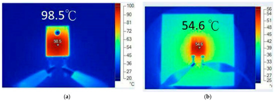
Figure 9.
Temperature field of the heating single chip. (a) Original single chip temperature. (b) Pasted graphene composite TIM (MSA13050).
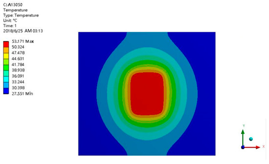
Figure 10.
Temperature field distribution of thermal conductivity of 235.5 W/mK.
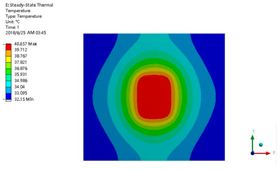
Figure 11.
Temperature field distribution of thermal conductivity of 1600 W/mK.
In Figure 11, the thermal conductivity is set to the theoretical value of 1600 W/mK, and the maximum temperature of the simulation result is 40.65 °C, which is obviously different from the experimental result, about 13.9 degrees.
It can be seen from the analysis results that the heat on the heat sink is diffused from the short side of the chip in the vertical direction to the edge of the heat sink, and the other side cannot reach the edge because the chip is rectangular, so the heat conduction distance in the up and down direction is longer. Comparing the results of the analysis, the parameters with a thermal conductivity of 1600 W/mK have better heat dissipation effects in terms of heat dissipation temperature and thermal diffusion, but the error with the experimental results is extremely large, but when the thermal conductivity is set to 235.5 W/mK The simulation results are in good agreement with the experimental results. This result shows that the graphene composite material cannot be effectively applied on TIMS regardless of the theoretical value of 5300 W/mK, or the plane heat transfer coefficient of 1600 W/mK after decreasing with thickness. The reason is that when the heat conduction path of the plane heat conduction is too thin, the heat diffusion efficiency is lowered, and the heat transfer requires a larger temperature difference to achieve heat transfer. On the contrary, the heat transfer coefficient 3 W/mK in the vertical direction seems to be relatively low in value, but because it is a thin composite material and the heat transfer area is large, heat can be efficiently transmitted from the heat source to the other end. Therefore, the TIMS parameters in the subsequent simulation will be set by the value of the heat transfer coefficient measured by HOT DISK.
4.6. VR Device Circuit Board Thermoelectric Analysis
The VR device in this study is a compact and closed space, and the solution is relatively time consuming due to the excessive number of meshes in the simulation, and the computer solving ability is limited. Therefore, the circuit board simulation of the VR device was carried out at an ambient temperature of 35 °C in an open space, and a commercially available graphene TIMS was used on the surface of the IC chip to investigate the temperature field after radiation dissipation.
The analyzed temperature field of the VR device board is shown in Figure 12a, showing that the 10 highest temperatures in the chip are on the backlight driver chip. The length and width of this chip are only 3 × 3 × 1 mm, but the power consumption is as high as 0.7 W, and the simulated temperature is 67.17. It can also be seen from the results that the thermal diffusion range and temperature on the left side of the MCPCB are both higher, because there are more high-power chips on the left side. After shooting with a thermal imager (Figure 12c), the high temperature area shows that the left temperature field is indeed higher than other regions. The highest temperature is at the upper left and the simulation results are different, because the simulation environment is assuming that the simulation is performed in an open space and there is no problem of heat accumulation in the outer casing, the heat generated by the heat source can be dissipated by natural convection. However, the result of the thermal imager is shown in Figure 12c. The metal core printed circuit board assembly (MCPCBA) is completely enclosed in the outer casing, so the gas in the closed environment can almost ignore the natural convection. In addition, the highest temperature and the second highest temperature position have a USB device for power supply and data transmission at the same time, so the temperature here is the highest. The temperature field distribution of the VR device can be reasonably predicted through simulation and experiment.
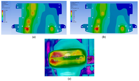
Figure 12.
Temperature fields of the PCBA within the VR device. (a) Original temperature field of PCBA within the VR device. (b) Temperature field of VR PCBA after pasting graphene TIM (MSA0095). (c) Thermal imaging temperature field of VR PCBA after pasting graphene TIM (MSA0095).
Figure 12b shows the temperature field of MCPCBA after the graphene TIM (MSA0095) is pasted on the chip. It can be found from the results that the temperature of the highest temperature backlight driven chip is reduced by 2.3 °C due to the good heat dissipation of graphene, to 64.87 °C, about 4% temperature drop.
4.7. LED Mode Establishment Result
In order to establish a closed and compact space simulation method for MCPCBA, an unfilled high-power LED lighting device is selected as the simulation object, and an air layer is set between the PC cover and the external aluminum fin, and an air volume is also set outside the overall lighting device. In this simulation, a conjugate heat transfer method is used to establish a heat transfer mode between the gas and the wall surface, and the Boussinesq approximation and the earth gravity are set in the inner air layer, so that the internal air heat transfer can be quickly and accurately assumed and simulated. The results of the integrating sphere experiment and the power analyzer are set to the boundary conditions. This method can simulate and predict the temperature field when the LED commercial device materials and related parameters are not obtained.
Figure 13a shows the analysis results of input 48 V, 0.15 A. According to the experimental results, the LED input is 5.5W evenly distributed to four LEDs. One LED body heat source is set to 1.375 W, and the IC is 1.14 W and 0.64 W respectively. After simulation, the maximum temperature of 77.2 °C is located at the bottom of the power control IC-SM1A chip. Figure 13b shows the isotherm diagram of 48 V, 0.15 A. It can be found that the heat transfer ability of the gas in the internal space is limited. The waste heat generated by the LED is transmitted to the heat dissipation fins and dissipated with the flow channel. Figure 14 shows the analysis result of input 60 V, 0.15A. The highest temperature is just below the power control chip. However, when the input wattage is 9 W, the temperature field generated by the heating chip is connected to the high temperature region of the upper LED, so the circuit components located here need special attention.
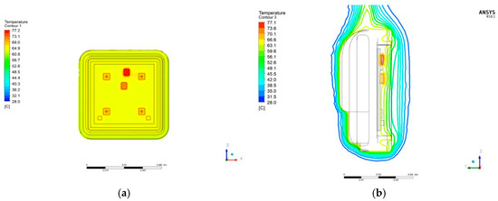
Figure 13.
Simulation result of the 48 V power LED. (a) Temperature field of the 48 V LED. (b) Isotherm diagram of 48 V power LED.
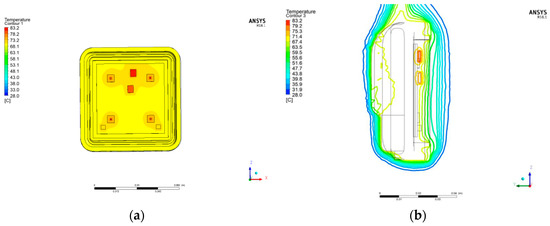
Figure 14.
Simulation result of the 60 V power LED. (a) Temperature field of the 60 V LED. (b) Isotherm diagram of the 60 V power LED.
4.8. Comparison of LED Thermal Radiation Effects
TIMs made of pure graphene and composite TIMs with added aluminum and copper at the bottom of the graphene are used for experiments and simulations to find the most effective way for graphene to be used in TIMs and effect of TIMs with different emissivity on high power LED devices in a closed and compact environment.
Table 1 shows MSA0095-graphene TIMs with an emissivity of 0.92, the highest temperature points measured by the experiment and simulation was compared, from the positions 3 and 4 of LED, the errors are 4% and 2% respectively. Table 2 compares the temperature result of using general TIMs and graphene TIMs with thermal emissivity. The experimental results are shown in Table 2 (a), after adhering the graphene TIMs, the temperature of the lower LED is significantly reduced by 6 °C, and the IC has a drop of 3 °C. This shows that the material property with higher heat radiation in the closed space can effectively transmit the temperature quickly, while the temperature of the upper LED drops less, because during the measurement, the thermoelectric coupling line causes a gap at the upper PC cover to cause thermal energy to escape through the air, resulting in a temperature drop. Table 2 (b) shows that the temperature drop of simulation results are more obvious than the experimental results. The reason is that the fins are aluminum materials under actual conditions, which also causes the far infrared rays emitted by graphene to be difficult to absorb. The experimental temperature drops because the graphene TIMs can effectively absorb and transfer the substrate thermal energy to the aluminum fins when the absorption and emissivity are the same. However, since the wavelength section is not set in the simulation, the heat energy effectively passes through the aluminum fins, which also causes a large temperature drop during the simulation.

Table 1.
Comparison of simulated and experimental temperature results of MSA0095-graphene TIM.

Table 2.
Comparison of temperature difference between graphene TIMs and general TIMs.
5. Conclusions
- (1)
- In this study, the conjugate heat transfer model has been built. Using the integrating sphere and the power analyzer, the actual powers for the dominant chips on PCBA are derived as the inputs in the FEA model. According to the results, the proposed model is feasible for the analysis of modern electronic devices with compact volume.
- (2)
- The effect of TIMs tuned with graphene are experimentally measured and compared with the simulation results with different heat transfer coefficients. The results show that the heat transfer coefficient of graphene is affected by the dimensions of the hot channel.
- (3)
- TIMs tuned with graphene can effectively reduce the operating temperature for the LED lamp. The temperature drop can be enhanced at a maximum value of 6.8 °C, and the simulation comparison is 3.9 °C.
Author Contributions
Conceptualization, A.-D.L., H.-W.T. and C.-M.H.; Data curation, S.Z.P. on and H.-W.T.; Formal analysis, H.-W.T.; Funding acquisition, A.-D.L., C.-Y.C. and C.-M.H.; Investigation, H.-W.T. and C.-M.H.; Project administration, A.-D.L., H.-W.T. and C.-M.H.; Resources, C.-Y.C. and C.-M.H.; Software, H.-W.T. and C.-M.H.; Supervision, A.-D.L., C.-Y.C. and C.-M.H.; Validation, H.-W.T. and C.-M.H.; Writing—original draft, H.-W.T.; Writing—review & editing, A.-D.L., S.Z.P. and C.-M.H. All authors have read and agreed to the published version of the manuscript.
Funding
This research received no external funding.
Conflicts of Interest
The authors declare no conflict of interest.
References
- Law, T.K.; Lim, F. Achieving Accurate Electro-Optical-Thermal Measurements of High-Power LEDs. In Proceedings of the 2015 IEEE 17th Electronics Packaging and Technology Conference, Singapore, 2–4 December 2015. [Google Scholar]
- Chernyakov, A.E.; Aladov, A.V. Experimental study of electroluminescence and temperature distribution in high-power AlGaInN LEDs & LED arrays. Microelectron. Reliab. 2017, 79, 457–461. [Google Scholar]
- Qian, C.; Li, Y. Studies of the light output properties for a GaN based blue LED using anelectro-optical simulation method. Microelectron. Reliab. 2017, 74, 173–178. [Google Scholar] [CrossRef]
- Marosy, G.; Kovács, Z. Diagnostics of LED-based streetlighting luminaires by means of thermal transient method. In Proceedings of the 2010 16th International Workshop on Thermal Investigations of ICs and Systems (THERMINIC), Barcelona, Spain, 6–8 October 2010. [Google Scholar]
- Elger, G.; Müller, D. Transient thermal analysis for accelerated reliability testing of LEDs. Microelectron. Reliab. 2016, 64, 605–609. [Google Scholar] [CrossRef]
- Kudsieh, N. High power LED assemblies for solid state lighting—Thermal analysis. Optik 2015, 126, 3452–3456. [Google Scholar] [CrossRef]
- Abdelmlek, K.B.; Araoud, Z. Effect of thermal conduction path deficiency on thermal properties of LEDs package. Appl. Therm. Eng. 2016, 102, 251–260. [Google Scholar] [CrossRef]
- Abdelmlek, K.B.; Araoud, Z. Optimization of the thermal distribution of multi-chip LED package. Appl. Therm. Eng. 2017, 126, 653–660. [Google Scholar] [CrossRef]
- Poppe, A. Simulation of LED based luminaires by using multi-domain compact models of LEDs and compact thermal models of their thermal environment. Microelectron. Reliab. 2017, 72, 65–74. [Google Scholar] [CrossRef]
- Zhang, K. Carbon nanotube thermal interface material for high-brightness light-emitting-diode cooling. Nanotechnology 2008, 19. [Google Scholar] [CrossRef] [PubMed]
- Novoselov, K.S. A roadmap for grapheme. Nature 2012, 490, 192–200. [Google Scholar] [CrossRef] [PubMed]
- Balandin, A.A. Balandin, Superior Thermal Conductivity of Single-Layer Graphene. Nano Lett. 2008, 8, 902–907. [Google Scholar] [CrossRef] [PubMed]
- Pettes, M.T. Thermal Transport in Three-Dimensional Foam Architectures of Few-Layer Graphene and Ultrathin Graphite. Nano Lett. 2012, 12, 2959–2964. [Google Scholar] [CrossRef] [PubMed]
- Fugallo, G. Thermal Conductivity of Graphene and Graphite: Collective Excitations and Mean Free Paths. Nano Lett. 2014, 14, 6109–6114. [Google Scholar] [CrossRef] [PubMed]
- Chai, J.C.; Lee, H.S.; Patankar, S.V. Finite volume method for radiation heat transfer. J. Thermophys. Heat Transf. 1994, 8, 419–425. [Google Scholar] [CrossRef]
- Ramamoorthy, B.; Cheng, G.C.; Koomullil, R.P.; Rahmani, R.K. Finite volume method for non-equilibrium radiative heat transfer. Int. J. Heat Mass Transf. 2013, 65, 670–681. [Google Scholar] [CrossRef]
- Sun, Y.; Zhang, X.; Howell, J.R. Evaluation of three different radiative transfer equation solvers for combined conduction and radiation heat transfer. J. Quant. Spectros. Radiat. Transf. 2016, 184, 262–273. [Google Scholar] [CrossRef]
- Sun, Y.; Zhang, X.; Howell, J.R. Assessment of different radiative transfer equation solvers for combined natural convection and radiation heat transfer problems. J. Quant. Spectros. Radiat. Transf. 2017, 194, 31–46. [Google Scholar] [CrossRef]
- Costa, M.A.D.; Costa, G.H.; dos Santos, A.S.; Schuch, L.; Pinheiro, J.R. A high efficiency autonomous street lighting system based on solar energy and LEDs. In Proceedings of the 2009 Brazilian Power Electronics Conference, Bonito-Mato Grosso do Sul, Brazil, 27 September–1 October 2009; pp. 265–273. [Google Scholar]
- Schirripa Spagnolo, G.; Leccese, F.; Leccisi, M. LED as Transmitter and Receiver of Light: A Simple Tool to Demonstration Photoelectric Effect. Crystals 2019, 9, 531. [Google Scholar] [CrossRef]
- T-Global Technology Co. Ltd. Official Website. Available online: www.tglobalcorp.com (accessed on 5 June 2018).
© 2019 by the authors. Licensee MDPI, Basel, Switzerland. This article is an open access article distributed under the terms and conditions of the Creative Commons Attribution (CC BY) license (http://creativecommons.org/licenses/by/4.0/).