Article

Multi-Level Analysis of On-Chip Optical Wireless Links

1
Department of Electrical, Electronic and Information Engineering “G. Marconi”, University of Bologna, 40136 Bologna, Italy
2
Department of Electrical and Information Engineering, Polytechnic of Bari, 70126 Bari, Italy
3
Department of Engineering, University of Ferrara, 44122 Ferrara, Italy
4
Barkhausen Institute, 01062 Dresden, Germany
*
Author to whom correspondence should be addressed.
Appl. Sci. 2020, 10(1), 196; https://doi.org/10.3390/app10010196
Submission received: 28 November 2019 / Revised: 22 December 2019 / Accepted: 23 December 2019 / Published: 25 December 2019
(This article belongs to the Section Electrical, Electronics and Communications Engineering)

Abstract

:

Featured Application

Optical wireless communication on-chip may represent a breakthrough in the development of chip multi-core-processors, paving the way towards kilo-cores architectures. Beneficial fallout can be then envisaged in many technical fields, like augmented/virtual-reality, artificial-intelligence, automotive communications and data-centers for cloud-computing.

Abstract

Networks-on-chip are being regarded as a promising solution to meet the on-going requirement for higher and higher computation capacity. In view of future kilo-cores architectures, electrical wired connections are likely to become inefficient and alternative technologies are being widely investigated. Wireless communications on chip may be therefore leveraged to overcome the bottleneck of physical interconnections. This work deals with wireless networks-on-chip at optical frequencies, which can simplify the network layout and reduce the communication latency, easing the antenna on-chip integration process at the same time. On the other end, optical wireless communication on-chip can be limited by the heavy propagation losses and the possible cross-link interference. Assessment of the optical wireless network in terms of bit error probability and maximum communication range is here investigated through a multi-level approach. Manifold aspects, concurring to the final system performance, are simultaneously taken into account, like the antenna radiation properties, the data-rate of the core-to core communication, the geometrical and electromagnetic layout of the chip and the noise and interference level. Simulations results suggest that communication up to some hundreds of μm can be pursued provided that the antenna design and/or the target data-rate are carefully tailored to the actual layout of the chip.

1. Introduction

Nowadays, the advent of applications in technical fields like augmented/virtual-reality, artificial-intelligence, automotive communications, data-centers for cloud-computing triggers a widespread demand for high computational power. Therefore, trends in computation processes are fostering the development of Chip-Multicore-Processors/High-Performance-Computing architectures, where many cores are integrated together to meet the request for the continuous performance growth [1]. In this framework, chips with up to one thousand cores have been envisaged as expected outcome of this new many-core era [2]. Nevertheless, providing the cores with mutual interconnections poses several challenges related to layout design, communication latency/bandwidth, and power consumption, with increasing complexity as the number of cores grows up [3,4].
In spite of its simplicity, traditional bus architectures cannot easily scale up to a large number of processing elements due to limitations in bandwidth and latency [1], and are likely to be discarded in favor of Networks-on-Chip (NoC), where wires and routers are embedded on the same chip with cores and cache banks [3,5]. Although NoC scalability is better compared to bus solutions, it is nevertheless still limited, as propagation delays and losses of electrical wires do not scale down at the same rate as transistors [6]. Optical interconnect can improve propagation issues, but on the other end Optical-Network-on-Chip (ONoC) may suffer from additional losses due to imperfect coupling with off-chip laser and/or electro-optical conversion, as well as from extra power-expenditure for the resonance frequency tuning of optical devices like micro-rings [6]. Furthermore, cross-talk risks threaten (O)NoC design, to an extent that becomes harsher as the number of processing elements increases and the network deployment becomes more tangled. 3D integration, where the vertical dimension is also exploited to stack different circuit components, can be a viable solution in some specific situations [7], but fabrication issues limit the implementation of on-chip multi-planar layouts on the mainstream technologies as Silicon Photonics.
In order to overcome the bottleneck of physical interconnections, Wireless Network on Chip (WiNoC) are being considered an interesting solution [3,4,5,8]. Since millimeter-wave antennas undergo obvious problems of on-chip integration, Optical Wireless Networks-on-Chip (OWiNoC) have been recently investigated [9,10], aiming at keeping the main benefits of WiNoC (short latency, simpler network design) but easing the antenna integration process. As wireless communications on-chip are expected to complement wired solutions, rather than to replace them [2,11], OWiNoC also benefit from full compatibility with optical, physical networks which may be also deployed on the same chip.
The design of OWiNoC encompasses several challenging tasks, spanning from optical antenna design and wireless channel modeling to management and mitigation of interference issues, which always rise up as the wireless propagation channel is inherently shared among simultaneous wireless communications. This paper aims at providing a comprehensive insight into these different aspects, with special attention to the impact of noise and interference on bit-error-probability and maximum achievable distances by means of simulations carried out in some reference, study cases. The main topic under investigation is the on-chip wireless optical communication in point-to-point links, and therefore any network optimization feature is simply not taken into account so far.
The paper is organized as follows: after a survey on previous studies and activities on networks-on-chip provided in Section 2, the main features of on-chip wireless links at optical frequency are outlined in Section 3. Interference issues and performance assessment in OWiNoC are addressed in Section 4, whereas the results of the simulations are discussed in Section 5. Some conclusions are finally drawn in Section 6.

2. Background on Networks-On-Chip

Scaling up multi-core chips through standard technologies for physical interconnects poses several performance issues like heat dissipation, latency and speed bottleneck, due to the physical limits of metallic tracks. Therefore, wireless solutions represent today a valid NoC breakthrough to overcome these problems [2,8], especially for long-haul ranges within the chip. According to the existing literature, WiNoC have been mainly investigated at frequency up to hundreds of GHz [12,13,14,15,16].
Although the alleged power savings (either in pJ/bit or mW/Gbps) of optical technologies for on-chip interconnections is nowadays still under debate [3,17], the advantages of large spectrum and wavelength-division multiplexing (WDM) seem anyway beneficial for thousand-cores chip.
Therefore, the extension of the wireless solution to the optical domain represents an interesting topic of investigation, also in light of the minor attention so far devoted to OWiNoC [10,18,19]. A survey on the major studies and papers already published on wired and wireless NoC is summarized in Table 1 for the sake of brevity.
A comprehensive performance assessment of a network-on-chip usually spans several different aspects such as the number of NoC elements (links, routing, switch elements) [2,23], the latency [2,12,17,24], the chip area [5,25], the communication distances [2], the data-rate [2], and the bit error probability (BEP) [2,22]. The analysis carried out in this paper is primarily focused on both the communication range and the BEP.

3. Physical Description of the On-Chip, Optical Wireless Link

Regardless of the many technological stages involved in its overall manufacturing process, an integrated circuit is often roughly represented as a layered structure as shown in Figure 1. The first stage of the process flow (front-end-of-line—FEOL) aims at the deployment of the electrical/electronic circuit components into the semiconductor (e.g., silicon) layer. Some metallization and dielectric layers are then interleaved in the next steps (back-end-of-line, BEOL), and holes are finally etched through the insulating material to connect the metallic layers, which provide the required interconnects among the circuit elements underneath [26].
Various viable solutions have been proposed in the literature for the inclusion of the optical layer in the chip stack. For example, the optical layer can be placed on-top of the electronic interconnection layers [27,28] as shown in Figure 1, or in plane with it [29,30,31]. The layer stack is finally completed by additional upper layers accounting for possible passivation/filling materials and for the outer package enclosure. It is worth mentioning that a further layer might be present, either on the top or at the bottom, corresponding to a possible heat sink.
The on-chip optical wireless communication indeed occurs in the optical layer, as sketched in Figure 1, which can be regarded as a wireless evolution of the on-chip optical wired link outlined in [6]. According to the OWiNoC paradigm, the optical layer is further split into a wireless and a wired part, the former consisting of the optical antennas spreading the core-to-core signals into the wireless channel, the latter including the optical elements interfacing the cores to the optical antennas.
This sketch of possible implementations of OWiNoC aims at introducing the main, representative features of the optical layer layout further addressed in the following subsections.

3.1. Physical Optical Interconnects

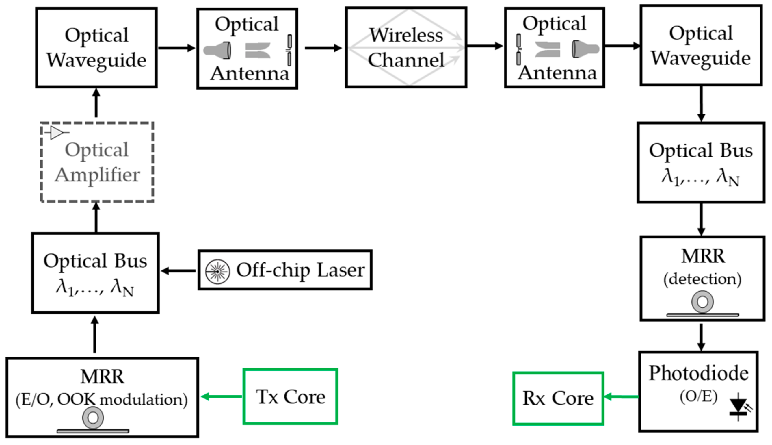
The source of the optical power at the transmitting link end can be an external off-chip laser coupled to the optical bus [11,32], emitting a nominal power PTX on the bus, steady in time according to the expected working temperature of commercial GPU/CPU architectures. Then, a dedicated micro ring resonator (MRR) can be used to provide both electrical-to-optical conversion [33] and On–Off Keying (OOK) Non-Return-to-Zero (NRZ) amplitude modulation [17] with a bandwidth Bopt over the optical carrier. The modulated signal is finally routed towards the optical antenna (see Section 3.2) and wirelessly spread within the chip. As shown in the block scheme in Figure 2, an integrated optical amplifier may be present before the transmitting antenna, in order to cope with the large path loss coming from the optical wireless channel and to push the received signal strength to the level required to drive the digital logic in the lower, electrical layer [6]. Beyond the wireless channel, the optical incoming field is first gathered by the optical receiving antenna, then directed into the optical bus and finally filtered off by another MRR. A photodiode (PD) with responsivity ηPD reconstitutes the OOK signal in the electrical domain, ready to be demodulated.
As long as the analysis is limited to a single link, symbols detection errors are due to the propagation impairments (briefly discussed in Section 3.3) and to the noise effects experienced by the optical communication system. Since the thermal noise is often acknowledged as the dominant noise contribution [34], other noise sources like the PD shot noise and the relative intensity noise of the laser have been neglected herein. Conversely, in a multi-link scenario mutual interference among the different, simultaneous communications may arise, to an extent greatly dependent on antennas radiation properties, spacing and position. These issues will be discussed more in detail in the following Section 4 and Section 5. Although an effective implementation of O(Wi)NoC could benefit from WDM [11,35,36], this work involves no multiplexing scheme (e.g., simulations are run with only one WDM channel), in order to focus the investigations on the influence of antennas and core distances, excluding any issues above the physical layer.

3.2. Optical Antennas

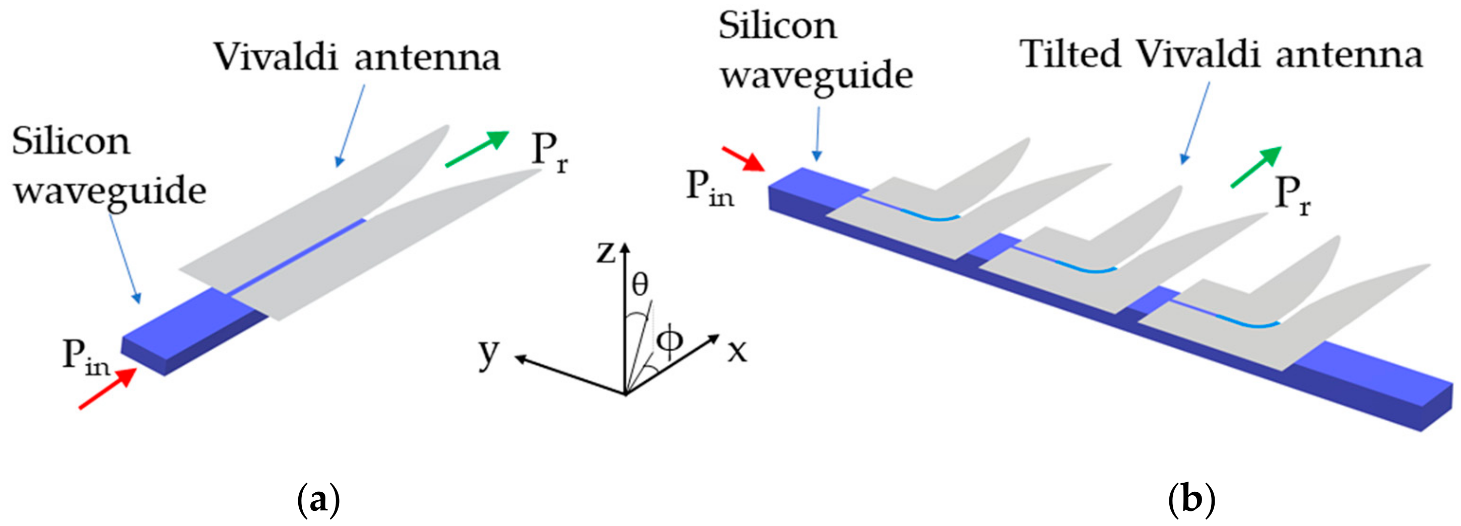
In order to evaluate the propagation and the performances of the wireless links in OWiNoC, some study cases based on different antenna configurations are here considered. Actually, the antenna coupled to the optical waveguide is one of the key elements in the OWiNoC design as it allows to switch from wireless to wired optical propagation and vice versa. At the transmitting section, the antenna radiates in the surrounding medium the optical signal that comes from the input waveguide. The radiated signal propagates wirelessly and it is then transferred to an output waveguide by the receiving antenna. The analysis of propagation and performance of point-to-point optical wireless links carried out in the following sections relies on the two configurations of plasmonic antennas shown in Figure 3a,b, respectively.
In particular, Figure 3a outlines the single antenna configuration [9], consisting of a silver plasmonic Vivaldi 1.75 μm long and 0.57 μm wide. The antenna is coupled to a silicon waveguide (0.38 μm × 0.22 μm) through a slotted plasmonic waveguide with length 1.63 μm. The optical signal (Pin) is launched into the Si waveguide and it is vertically coupled to a plasmonic slot waveguide, which is separated from the dielectric one by a dielectric layer. The antenna, obtained by shaping the plasmonic slot waveguide according to a Vivaldi profile, radiates the optical signal in the surrounding medium (Pr) in the positive x direction. The behavior is reciprocal when the antenna is used as receiver. The antenna array configuration is instead represented in Figure 3b [37], where multiple Vivaldi antennas are fed by the same Si waveguide. Each antenna is 90° tilted with respect to the Si waveguide. This geometrical rotation allows a 90°-tilt of the radiation pattern with respect to the waveguide propagation direction. Moreover, this layout implements a travelling wave excitation of the array, which guarantees compact sizes of the overall radiator (about 3.5 µm × 8.7 µm for a 5-antennas array).
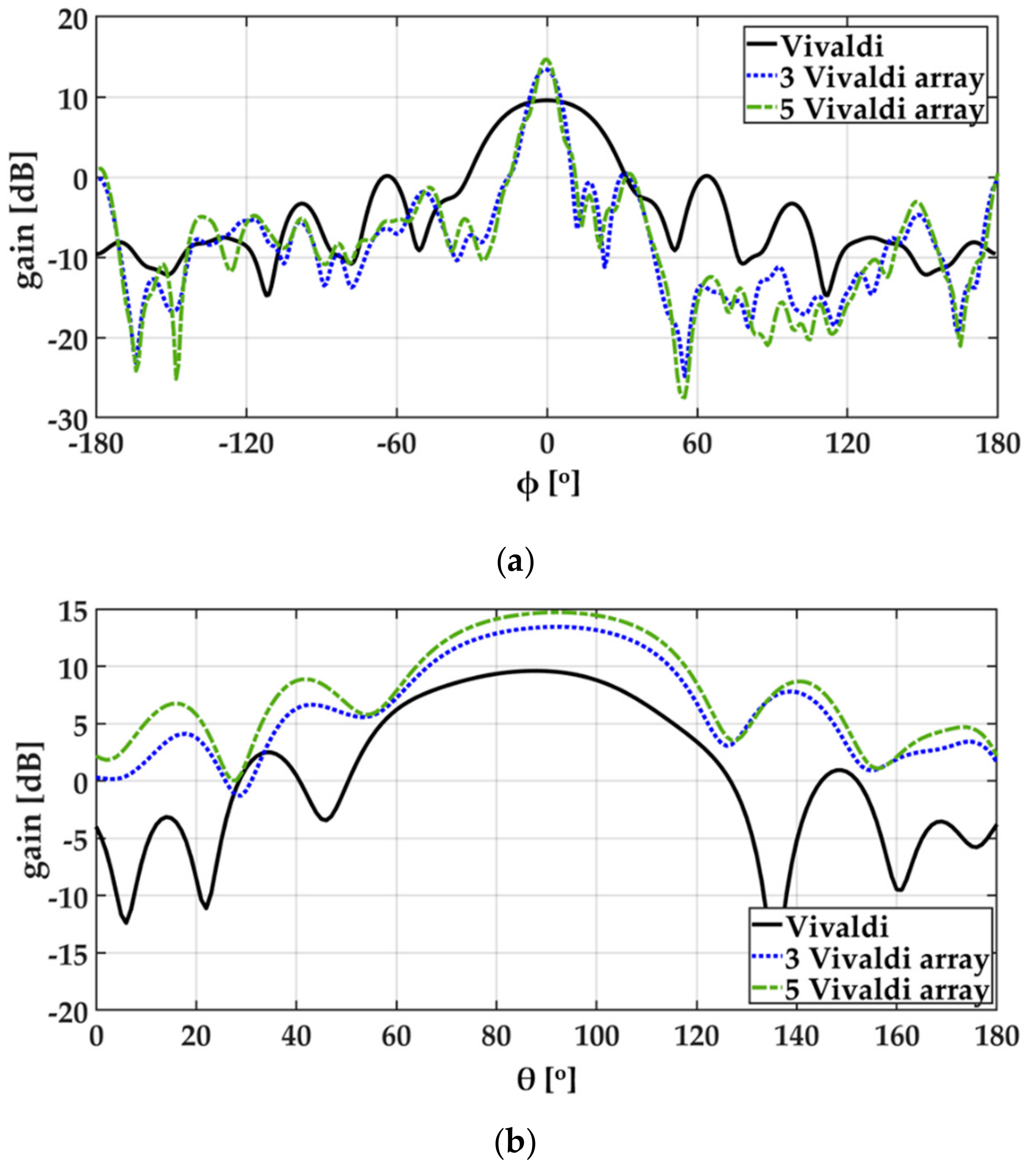
Although the details on the design and on the radiation characteristics of the two antenna configurations are provided in [9,37] the antennas gain function in the ϕ = 0° (xz) and in the θ = 90° (xy) planes is plotted in Figure 4a and in Figure 4b for the sake of self-consistency. In particular, the reported curves refer to the single Vivaldi antenna (black continuous), and to the antenna array with N = 3 (blue dotted) and with N = 5 (green dashed) elements. The results shown in Figure 4 were obtained by the FDTD simulations of the antennas radiating in an infinite homogeneous medium with refraction index n = 1.44 (i.e., corresponding to silica, see Table 2), which was implemented in the numerical model by perfectly matched layer boundary conditions. The radiation diagrams were calculated by near-to-far field projections of the fields recorded on a closed box, surrounding the different antenna configurations.
The three antenna layouts correspond to different antenna gain values (G = 9.90 dB, G = 13.45 dB and G = 14.70 dB for the single, three- and five elements configuration, respectively), which take also into account the actual efficiency in the electromagnetic coupling between the silicon waveguide and the transmitting/receiving antenna. These antennas are exploited in the following to assess the impact of different radiation properties on the electromagnetic propagation in the multilayer environment and on the point-to-point link performance.
It is worth pointing out that the multi-level numerical approach proposed in this paper is virtually applicable to every optical antenna configuration, such as multiple-feed arrays of plasmonic antennas [38] or dielectric antennas [19,39] and to every multilayered environment.

3.3. Optical Wireless Channel

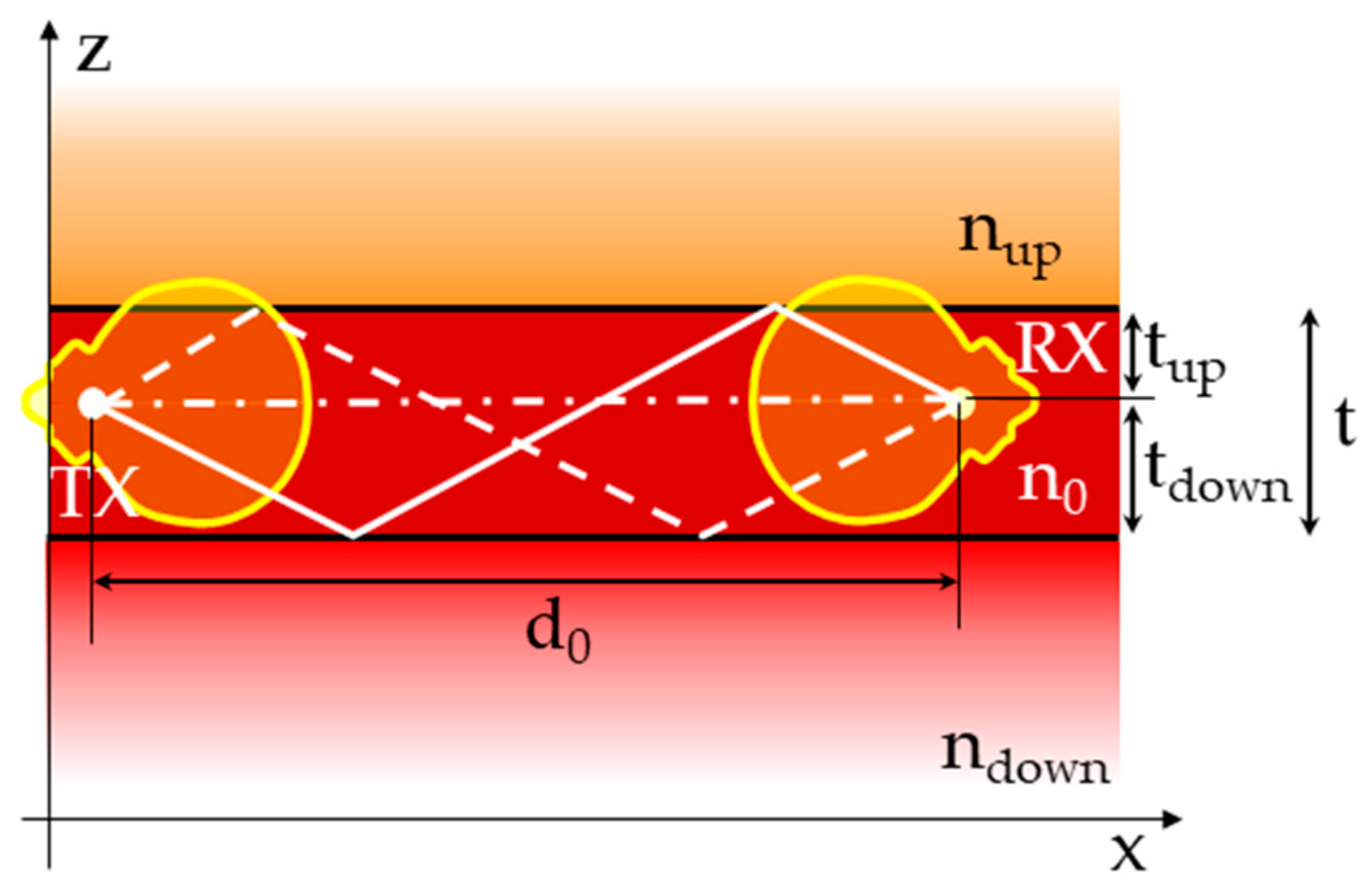
According to the chip layered representation, the electromagnetic waves springing out from the on-chip transmitting antenna are expected to bounce onto the interfaces between the layers, thus triggering multipath effects [8,10,14,16,18]. Assuming the antennas buried in a SiO2 layer limited by two different, unbounded media on the lower and on the upper side [10,18], multipath is fundamentally generated by the multiple reflections between the interfaces (Figure 5) and can be evaluated by means of the Ray Tracing (RT) approach discussed in [10]. It is worth pointing out that the RT modeling is particularly tailored to the investigation of the optical wireless channel, as geometrical optics is known to be an asymptotic theory, i.e., its accuracy increases at higher frequency.
Compared to other wireless networks, where the possible mobility of nodes and/or objects over quite large areas produces random-like fluctuations of the received signal intensity, the on-chip wireless channel is confined and static, as the chip layout is fixed and known beforehand [24]. Therefore, propagation modeling at chip-level is quite well fit for characterization through deterministic approaches like RT, which require the a priori knowledge of the physical environment.
In order to run the RT simulation, both geometrical and electromagnetic properties of the link have to be set, the former referring to the SiO2 layer thickness (t in Figure 5), to the antennas distance from the interfaces (tup and tdown) and to the link distance (d0), the latter consisting of the materials refraction index (ndown, n0 and nup). A 3D representation of the antenna radiation patterns is also necessary as input file. The assessment carried out in this work is limited to the Vivaldi antenna configurations briefly discussed in the previous section [9,37], but any other radiation diagrams can be embedded into the RT tool, provided that they are encoded in the required format.
Although propagation in Figure 5 is limited to the xz plane, a 3D description of the antenna patterns is nevertheless helpful, as the RT model can be then easily run regardless of the antenna orientation with respect to the propagation plane, e.g., for the assessment of the power received from an interfering transmitter. The geometrical/electromagnetic parameters considered herein for the RT simulations are summarized in Table 2.

4. Performance Assessment of Optical Wireless Networks-on-Chip

The performance of a communication link is often characterized in terms of bit error probability (BEP). In a binary, optical communication system, BEP can be defined as the probability that the received photocurrent transmitting 0 is detected above the decision threshold, or it is detected below the threshold while transmitting 1. In the literature related to Wireless NoC [4,19,22] BEP is usually experimentally assessed or estimated by means of analytical formulas for single link, which can be computed based on the estimated value of the received power after the photodiode. However, wireless network design always requires a careful study of cross-link interferences, which may occur among simultaneously links exploiting the same (optical) channel. In fact, the spatial reuse of optical wavelengths improves significantly the transport capacity in OWiNoC, since the number of simultaneous communications will not be limited by the number of available wavelengths. On the other hand, wavelength reuse can trigger co-channel interference, which can harshly degrade the system performance, if not effectively handled and mitigated. Hence, the design of OWiNoC can greatly benefit from an interference-aware framework for BEP evaluation. By exploiting the analytical approach in [40,41] compliance of different link configurations with the target performance for the on-chip communication can be investigated.
In a general OWiNoC scenario, I + 1 transmitters using the same optical wavelength can be present, with only one useful transmitter TX0 for the desired receiver RX0 and the other I transmitters (TX1, TX2, …, TXI) causing interference to RX0 while communicating with their corresponding receivers. The optical power (i.e., the power of the unmodulated optical carrier) of the received desired signal is here denoted by P0, and the normalized optical power of the i-th received interfering signal is denoted by xi = Pi/P0, with i = 1, 2, …, I. The received power values depend on the radiation properties of the antennas, their spacing and orientation and on the propagation characteristics of links.
In this paper, BEP performance is investigated for the following, two simple OWiNoC scenarios. In the former case (Figure 6a), two parallel links, separated by the distance Δ, carry data in the same direction up to a distance d0. The optical signal from TX0 to RX0 is exposed to the interference of the signal coming from TX1, which may therefore affect the communication BEP. In the latter scenario (Figure 6b), an additional, parallel, interfering link is introduced at a distance Δ’ from the reference link TX0–RX0.
For each OWiNoC scenario, the received powers can be evaluated with FDTD or RT tools as discussed in the following Section 5.1. For a given transmitted optical input power Pin, the received power can be computed as Pi = PGi⋅Pin, where PGi is the path gain of the channel between the i-th transmitter and the reference receiver RX0.
The performance analysis carried out in Section 5.2 assumes that all links use intensity modulation OOK with NRZ pulses and direct detection. If the bits of the data sources have the same probability of 1/2, the average power Pin,av of the modulated signal is one half of the power of the unmodulated carrier. The BEP is evaluated as a function of signal-to-noise ratio (SNR) and normalized interference powers (xi, i = 1,…,I), where SNR = 4γ2, with γ = ηPD⋅P0/(2σth) depends on the unmodulated received power, the responsivity ηPD of the photodetector and the standard deviation σth of the additive Gaussian noise at the receiver. Since the thermal noise is the dominant noise most often associated with p-i-n receivers (at least for low level of detected power) [34], noise variance σth2 does not depend on transmitted bits and can be computed as σth2 = 4⋅K⋅Teq/(2⋅RL⋅T), where K is the Boltzman’s constant, Teq is the noise temperature of the receiver, RL is the resistance of the receiver and T = 1/Rb is the bit interval of the transmitted data. Here, as a reference, the values of system parameters in Table 3 are considered for the numerical evaluations [34,42].
In particular, the method in [40,41] is used to analytically evaluate the BEP by taking into account all the random variables (RVs) in the optical wireless communication system. The RVs include the bits sent by all transmitters, the optical carriers phases and time offsets of the asynchronous interfering links, and the Gaussian noise.
It is worth mentioning that inter-symbol interference is here neglected, i.e., the delay spread related to multipath propagation is assumed (much) smaller than the bit time interval. Based on a reverberation model, delay spread was estimated equal to some nsec. at mmWave (300 GHz) and roughly one order of magnitude lower at 100 THz [24]. As the on-chip environment is not fully reverberating, first experimental assessments in the mmWave band returned lower values, e.g., equal to 100 psec. in [12], which might therefore correspond to about 10 psec. in the infrared/optical bands. In order to avoid inter-symbol interference, T >> 10 psec. is required, i.e., Rb ≤ 10 Gbit/s is approximately needed. According to these considerations, Rb = 10 Gbit/sec. has been therefore set in Table 3 as a main target. This value is of the same order of magnitude as the channel throughput considered in previous studies [4,6,8,17,35,43].

5. Results and Discussion

This section includes the results of the simulations carried out in some study cases, aiming at the assessment of OWiNoC link performance in terms of SNR and BEP. The outcomes of the corresponding link-level RT simulations are discussed, highlighting some general trends and constraints for the feasibility of wireless networks-on-chip at optical frequency.

5.1. Ray Tracing Analysis of the Optical Wireless Channel

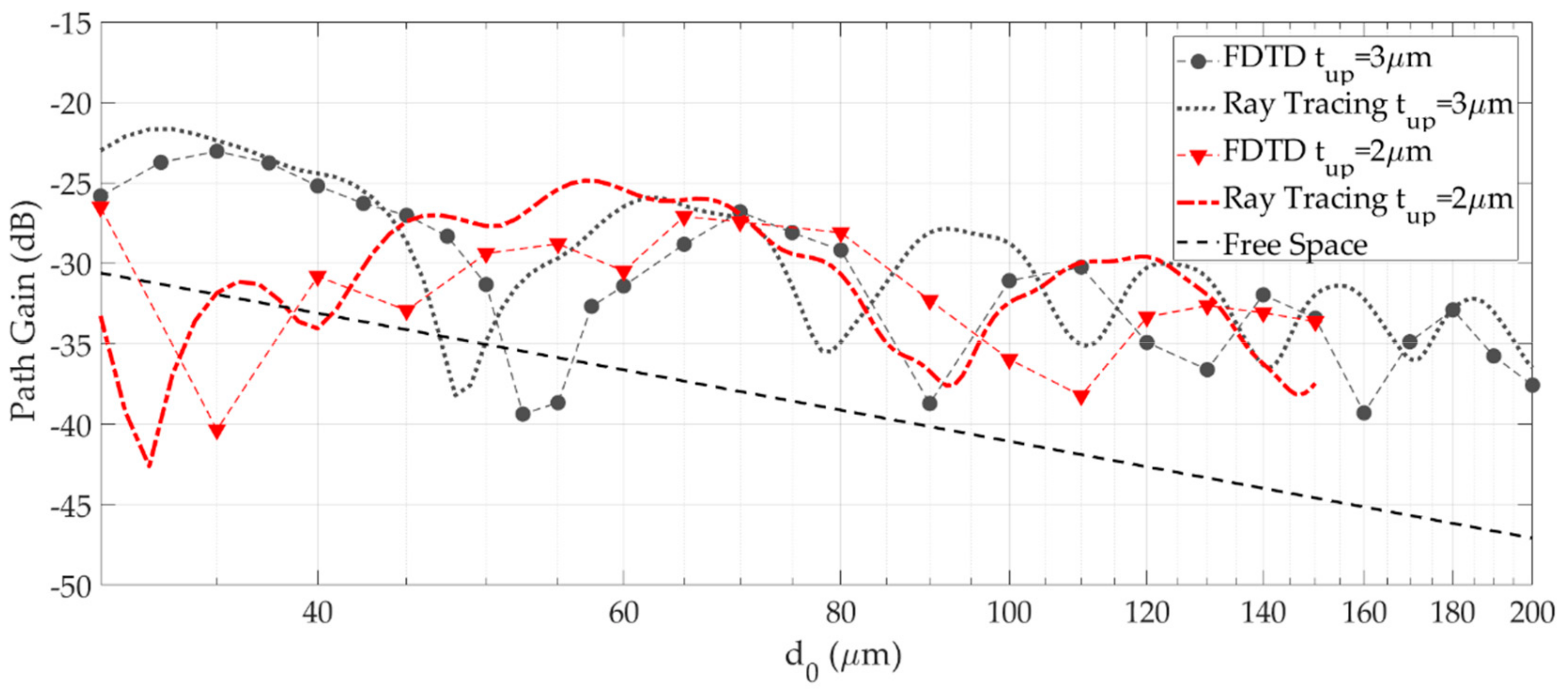
RT reliability for on-chip propagation prediction is shown in Figure 7 against FDTD simulations of an optical wireless link between the plasmonic Vivaldi antenna shown in Figure 3a and presented in [9] and for different thickness of the silica layer. Path Gain (PG) plotted in Figure 7 is the ratio between the power seized by the receiving antenna and the power supplied to the transmitting one. In spite of the very different computation effort required by RT and FDTD, with computation time respectively equal to few seconds and several hours, the overall root mean square error is equal to 4.5 dB. Considering that RT accuracy for PG modeling in cellular systems for personal communications may commonly correspond to an average RMSE of several dBs, results are here quite in agreement. According to this outcome, surface wave propagation, which has been sometimes claimed as a major propagation mechanism [13,16] does not seem so significant, at least in the considered situations. In fact, it would be accounted for by the FDTD simulation only and therefore would result in a much poorer comparison between the models. The sensitivity of the PG values to the SiO2 layer thickness in Figure 7 provides further evidence of the strong multipath effect affecting the on-chip propagation, as variations comparable to the wavelength completely change the interference pattern of the rays, thus resulting in a shift of the maxima/minima of the power level.
It is worth pointing out that in both cases PG is on the average greater compared to what it would be in free space (dotted line in Figure 7), thus meaning that on-chip wireless communications can benefit from better propagation conditions than free space. As outlined in [10], this is the result of a sort of guiding effect triggered by the multiple reflections within the antenna layer up to a distance that depends on the antenna radiation properties, the material at the interfaces and the thickness of the layers [10].
Taking advantage of the computational agility of RT, the impact of materials, antennas and layers thickness on the optical wireless channel is further investigated in Figure 8. In addition to purely dielectric interfaces, which are representative on the on-chip layered environment, highly reflective interfaces has been also taken into account for the sake of comparison. In the RT tool, they have been implemented as metals based on the Drude theory [44]. As shown in Figure 8, interference is clearly stressed if total reflection occurs at the interface(s)—e.g., with metal filling the lower layer instead of silicon—as the ray’s intensities keep similar compared to the case where a greater power leakage occurs at the interface.
Increasing the antenna gain—e.g., considering an array of three/five plasmonic Vivaldi antennas instead of a single one—results in a greater PG on the average, although it can also impair the aforementioned guiding effect, to the extent that pursuing a directivity as large as possible may not represent a convenient target [10].
Finally, a reduction in the antenna layer thickness seems to alleviate multipath effects in Figure 8, although at the expense of the power decay trend at larger distance [10]. Therefore, the choice of the best thickness should also take into account the communication distance target. More in general, many aspects concur to the system performance in a somehow interlaced way, i.e., it is hardly possible to optimize a single parameter regardless of the others. This is the main motivation for the link-level assessment of the optical wireless communication on-chip discussed in this work.

5.2. Link Level Assessment of Bit Error Probability

BEP results are first presented for the scenario with one interfering link (Figure 6a), by considering the reference system parameters of Table 3, Vivaldi optical antennas and path gain values obtained from RT simulations. Since the BEP depends on the positions of both desired and interfering transmitters, the results are displayed in the form of a two-dimensional map where the BEP is reported for each pair of values (d,Δ).
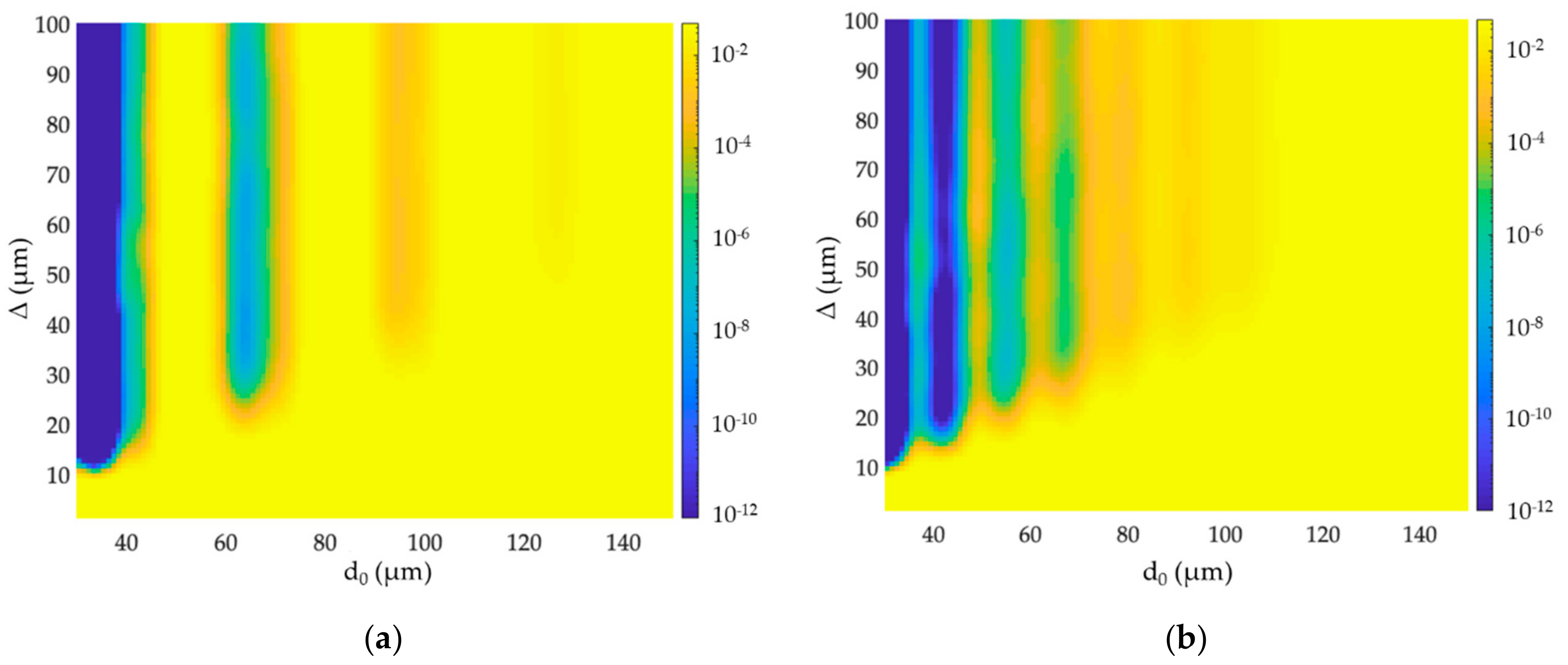
The results in Figure 9a are derived for links using single plasmonic Vivaldi antennas placed in the middle of a SiO2 layer with 6 μm thickness. According to the system parameters values in Table 3, a received power at least equal to −25.7 dBm is necessary to overcome the noise level to the extent corresponding to a target BEP = 10−6. Link performance is significantly impaired by the multipath effects, which make the link reliability not uniform in the parameter space (d,Δ) and fully unsatisfactory for d > 70 μm due to the noise level, and for Δ/d < 1/3 due to the interference. The link is unreliable in a wide range of d values between 40 and 60 μm due to a multipath induced path gain notch (Figure 8). The domains of the (d,Δ) space with BEP lower than the target represent the coverage areas for the link (light to dark blue in Figure 9a).
As the multipath conditions change by varying the SiO2 layer thickness (Figure 7, Figure 8) also the coverage zones are likely to change accordingly. This is illustrated in Figure 9b where the thickness of the SiO2 layer is decreased to 4 μm. Comparison of the two figures shows that the width of path gain holes is reduced, but the maximum coverage shrinks to d < 55 μm at the same time due to a worse range dependence of PG.
In summary, on-chip wireless optical communications between plasmonic Vivaldi antenna buried in a few μm silica layer are mainly noise limited, with a maximum coverage distance lower than 100 μm. Interference represents a significant issue only in case the interfering links are quite close, with spacing not exceeding few tens of μm.
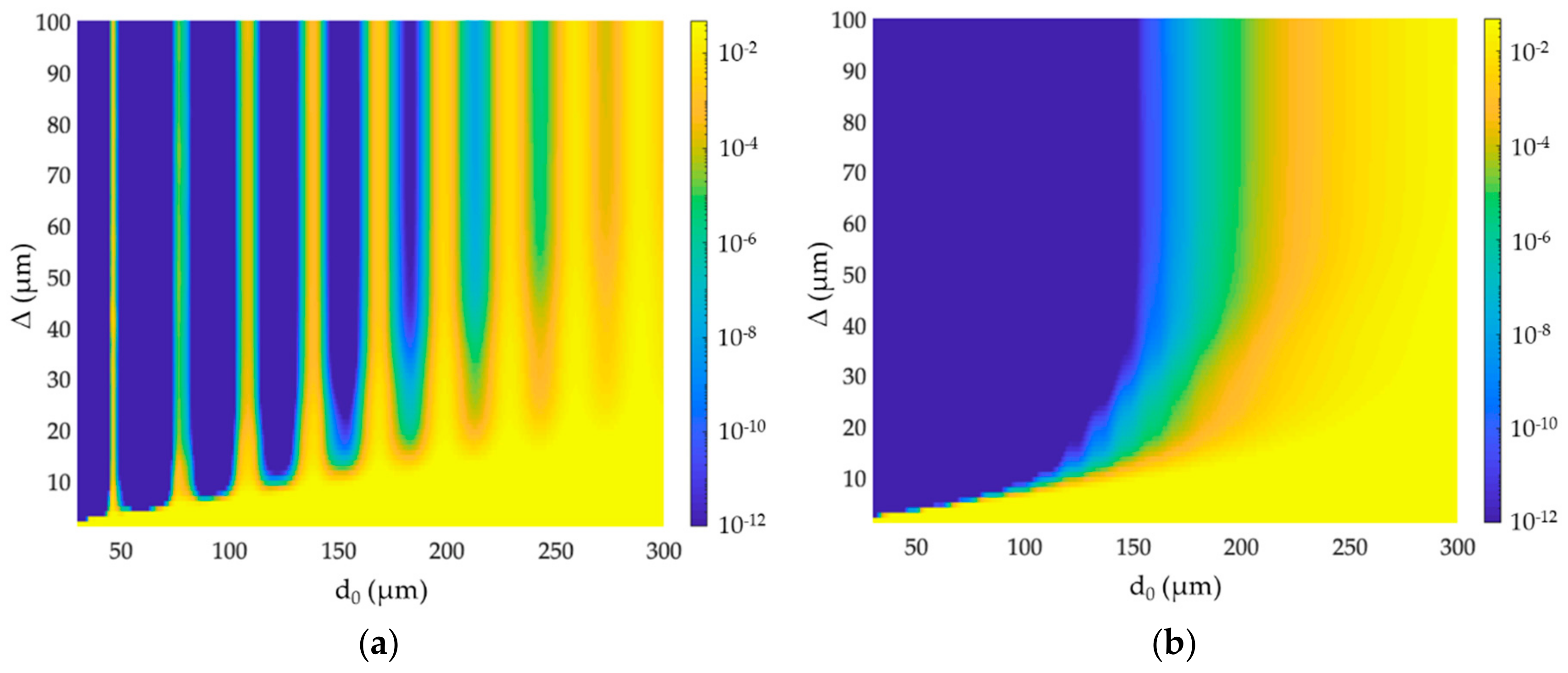
To extend the coverage region of a noise limited link, antennas should be designed to have a larger gain. As shown Figure 8, this may be accomplished with (Vivaldi) antenna arrays. The path gain increases by nearly 6 dB with 3 elements array and by nearly 8 dB with 5 elements array. An array of 5 plasmonic Vivaldi antenna in a SiO2 layer with thickness of 6 μm is considered in Figure 10a. As expected, the coverage zones are larger than those in Figure 9a, with a maximum communication distance equal to nearly 240 μm. Since the antenna array has a narrower beamwidth than the single element, the link is also more protected against interference, with interfering effects basically vanishing for Δ/d > 1/12. Moreover, the coverage is more uniform in the (d, Δ) domain, because the increase in the antenna gain reduces the occurrence of situation where the received signal intensity drops below the detection threshold.
Figure 10b shows the BEP map obtained with a 5-element Vivaldi antenna array and SiO2 thickness of 4 μm. Similarly to the results shown in Figure 9b, the thinner dielectric layer mitigates the multipath effects by smoothing the path gain notches, and therefore the coverage area turns out to be more uniform on the whole. Nevertheless, it also becomes smaller compared to Figure 10a, with a maximum communication range equal to nearly 180 μm. This value is smaller than the corresponding value in Figure 10a, as expected, because the path gain decays more rapidly at large distances if the layer thickness is reduced (see Figure 8).
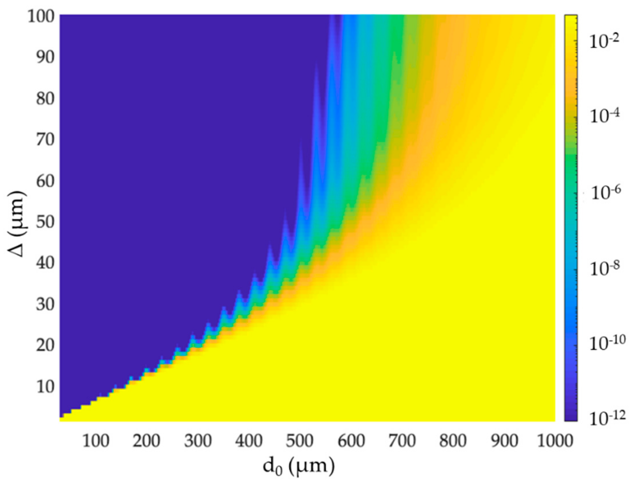
In order to stretch the extension of the coverage zone pursuing its smoothness at the same time, a possible option is the reduction of data rate requirements for the communication link. In fact, with a smaller data-rate the noise bandwidth in the receiver scales down as well, whereas the resistance RL can be scaled up because of the reduced receiver bandwidth requirements. In this way, the noise power level decreases and the receiver sensitivity increases. The BEP map in Figure 11 refers to the same situation considered in Figure 10a with data-rate Rb = 1 Gbit/s and RL = 10 kΩ. The coverage zone uniformly extends to a maximum distance of nearly 600 μm, provided that the links spacing is large enough to keep interference under control.
This result also highlights the existence of a further trade-off between wireless communication distance and data-rate, which might be taken into account in the design of the wireless network. Preserving reliable communications with data-rate of the order of 10 Gbit/s even at longer distances might be possible, provided that a greater design efficiency is pursued, e.g., improving the coupling with the off-chip laser, or increasing the gain of the antennas and/or the responsivity of the photodiode.
The scenario with two interfering links is finally addressed in Figure 12, where Δ = Δ’ is considered for the sake of simplicity. As for Figure 10a, 5-element Vivaldi antenna arrays and thickness of the SiO2 layer equal to 6 μm are assumed. Although noise is still the heaviest limiting factor, interference is doubled and its effect is therefore slightly increased, hampering the optical communication when Δ/d < 1/8 approximately. Hence, in the presence of more interfering links, the inter-link distance Δ has to be increased to keep the same protection level against interference. It should be noted that the value of Δ/d (or the values of Δ1/d, …, Δi/d, in a more general setting) that limits the coverage zones depends on the antenna radiation diagram, the number of the interferers and their power, which has to be evaluated for each specific application scenario.

6. Conclusions

Optical wireless networks-on-chip are investigated in this work by means of simulations carried out in some reference cases and according to a multi-level analysis, i.e., taking into account the main factors simultaneously affecting the performance of the on-chip, point-to-point communication. In particular, bit error-probability and communication range have been assessed in relation to the antenna radiation properties, the geometry and the constituting material of the chip, the mutual position of the interfering links and other system parameters like the data-rate, the noise power and the photo-diode responsivity at the receiver side.
Results show that in all the considered cases communications seem primarily limited by noise, with interference representing an issue only if the interfering links are quite close each other. For instance, in presence of one/two interfering links equipped with plasmonic Vivaldi antennas (gain ~10 dB), interference effect is basically negligible (compared to noise) as the links spacing is larger than few tens of μm. The communication range compliant with a target data rate of 10 Gbit/s turns out to be lower than 100 μm when the antennas are buried in a few μm silica layer, whereas it is more than doubled if a 5 dB gain increase is achieved resorting to Vivaldi array configurations. Further extension of the coverage area up to some hundreds of μm can be accomplished reducing the data-rate, as long as this may be acceptable. Otherwise, to keep the channel throughput to values fully competitive with other interconnect technologies, further efforts on the project of OWiNoC are required, e.g., aimed at the design of optical nano-antennas with larger gain.
Regardless of its extension, uniformity of the coverage area is jeopardized by multipath propagation, which can result in spots where communications reliability is prevented by the heavy multipath loss. Reducing the thickness of the dielectric layer including the antennas can contrast this multipath effect, but it would also worsen the received power range dependence at the same time.
In conclusion, as many factors simultaneously concur to the overall link performance in a somehow interlaced fashion, the optimization of each design parameter is likely to be possible only in the framework of a comprehensive, multi-level assessment.

Author Contributions

Conceptualization: F.F., M.B., G.C., V.T., G.B. and V.P. Methodology: F.F., M.B., G.C., V.T., G.B. and V.P. Software: F.F., M.B., G.C., V.T., G.B., M.Z., J.S.D. and B.A. Validation: F.F., G.B., V.T. and J.S.D. Investigation: F.F., M.B., G.C., V.T., G.B., M.Z., J.S.D., J.N., B.A. and V.P. Data curation: F.F., M.B., G.C., V.T., G.B., J.S.D. and B.A. Writing—original draft preparation, F.F., G.C., V.T., G.B., M.Z, and J.N. Writing—review and editing: F.F., M.B., G.C., V.T., G.B., J.S.D., J.N., B.A. and V.P. Supervision: F.F. All authors have read and agreed to the published version of the manuscript.

Funding

This research was funded by the Italian Ministry of Education, University and Research (MIUR) in the framework of the PRIN 2015 “Wireless Networks through on-chip Optical Technology—WiNOT” Project (20155EA8BC-PE7).

Conflicts of Interest

The authors declare no conflict of interest.

References

  1. Blake, G.; Dreslinski, R.G.; Mudge, T. A survey of multicore processors. IEEE Signal. Process. Mag. 2009, 26, 26–37. [Google Scholar] [CrossRef]
  2. Abadal, S.; Mestres, A.; Torrellas, J.; Alarcon, E.; Cabellos-Aparicio, A. Medium Access Control in Wireless Network-on-Chip: A Context Analysis. IEEE Commun. Mag. 2018, 56, 172–178. [Google Scholar] [CrossRef] [Green Version]
  3. Karkar, A.; Mak, T.; Tong, K.-F.; Yakovlev, A. A Survey of Emerging Interconnects for On-Chip Efficient Multicast and Broadcast in Many-Cores. IEEE Circuits Syst. Mag. 2016, 16, 58–72. [Google Scholar] [CrossRef] [Green Version]
  4. Deb, S.; Ganguly, A.; Pande, P.P.; Belzer, B.; Heo, D. Wireless NoC as Interconnection Backbone for Multicore Chips: Promises and Challenges. IEEE J. Emerg. Sel. Top. Circuits Syst. 2012, 2, 228–238. [Google Scholar] [CrossRef] [Green Version]
  5. Abdal, S.; Iannazzo, M.; Nemirovsky, M.; Cabellos-Aparicio, A.; Lee, H.; Alarcon, E. On the Area and Energy Scalability of Wireless Network-on-Chip: A Model-Based Benchmarked Design Space Exploration. IEEE Trans. Netw. 2015, 23, 1501–1513. [Google Scholar] [CrossRef]
  6. Werner, S.; Navaridas, J.; Lujan, M. A Survey on Optical Network-on-Chip Architectures. ACM Comput. Surv. J. 2018, 50, 89. [Google Scholar] [CrossRef]
  7. Alam, B.; Veroli, A.; Benedetti, A. Analysis on vertical directional couplers with long range surface plasmons for multilayer optical routing. J. Appl. Phys. 2016, 120. [Google Scholar] [CrossRef]
  8. Matolak, D.W.; Kodi, A.; Kaya, S.; Di Tomaso, D.; Laha, S.; Rayess, W. Wireless Networks-on-Chips: Architecture, Wireless Channel, and Devices. IEEE Wirel. Commun. 2012, 19, 58–65. [Google Scholar] [CrossRef] [Green Version]
  9. Bellanca, G.; Calò, G.; Kaplan, A.E.; Bassi, P.; Petruzzelli, V. Integrated Vivaldi plasmonic antenna for wireless on-chip optical communications. Opt. Express 2017, 25, 16214–16227. [Google Scholar] [CrossRef]
  10. Fuschini, F.; Barbiroli, M.; Zoli, M.; Bellanca, G.; Calò, G.; Bassi, P.; Petruzzelli, V. Ray tracing modeling of electromagnetic propagation for on-chip wireless optical communications. J. Low Power Electron. Appl. 2018, 8, 39. [Google Scholar] [CrossRef] [Green Version]
  11. Karanth, A.; Kaya, S.; Sikder, A.M.; Louri, A.; Laha, S.; Carbaugh, D.; Xin, H.; Wu, J.; DiTomaso, D. Sustainability in Network-on-Chips by Exploring Heterogeneity in Emerging Technologies. IEEE Trans. Sustain. Comput. 2019, 4, 293–307. [Google Scholar] [CrossRef]
  12. Zhang, Y.P.; Chen, Z.M.; Sui, M. Propagation Mechanisms of Radio Waves over Intra-Chip Channels with Integrated Antennas: Frequency-Domain Measurements and Time Domain Analysis. IEEE Trans. Antennas Propag. 2007, 55, 2900–2906. [Google Scholar] [CrossRef]
  13. Yan, L.; Hanson, G.W. Wave Propagation Mechanisms for Intra-Chip Communications. IEEE Trans. Antennas Propag. 2009, 57, 2715–2724. [Google Scholar]
  14. El Masri, I.; Martin, P.-M.; Mondal, H.K.; Allanic, R.; Le Gouguec, T.; Quendo, C.; Roland, C.; Diguet, J.-P. Accurate Channel Models for Realistic Design Space Exploration of Future Wireless NoCs. In Proceedings of the 12th IEEE/ACM International Symposium on Networks-on-Chip, Turin, Italy, 4–5 October 2018. [Google Scholar]
  15. Timoneda, X.; Cabellos-Aparicio, A.; Manessis, D.; Alarcon, E.; Abadal, S. Channel Characterization for Chip-scale Wireless Communications within Computing Packages. In Proceedings of the 12th IEEE/ACM International Symposium on Networks-on-Chip, Turin, Italy, 4–5 October 2018. [Google Scholar]
  16. Gade, S.H.; Rout, S.S.; Deb, S. On-Chip Wireless Channel Propagation: Impact of Antenna Directionality and Placement on Channel Performance. In Proceedings of the 12th IEEE/ACM International Symposium on Networks-on-Chip, Turin, Italy, 4–5 October 2018. [Google Scholar]
  17. Laha, S.; Kaya, S.; Matolak, D.W.; Rayess, W.; DiTomaso, D.; Kodi, A. A New Frontier in Ultralow Power Wireless Links: Network-on-Chip and Chip-to-Chip Interconnects. IEEE Trans. Comput. Aided Des. Integr. Circuits Syst. 2015, 34, 186–198. [Google Scholar] [CrossRef]
  18. Nafari, M.; Feng, L.; Jornet, J.M. On-chip Wireless Optical Channel Modeling for Massive Multi-core Computing Architectures. In Proceedings of the 2017 IEEE Wireless Communications and Networking Conference, San Francisco, CA, USA, 19–22 March 2017. [Google Scholar]
  19. Garcia-Meca, C.; Lechago, S.; Brimont, A.; Griol, A.; Mas, S.; Sanchez, L.; Bellieres, L.; Losilla, N.S.; Martì, J. On-chip wireless silicon photonics: From reconfigurable interconnects to lab-on-chip devices. Light: Sci. Appl. 2017, 6, e17053. [Google Scholar] [CrossRef]
  20. Miller, D.A.B. Device Requirements for Optical Interconnects to Silicon Chips. Proc. IEEE 2009, 97, 1166–1185. [Google Scholar] [CrossRef] [Green Version]
  21. Benini, L.; De Micheli, G. Networks on chips: A new SoC paradigm. Computer 2002, 35, 70–78. [Google Scholar] [CrossRef] [Green Version]
  22. Duong, L.H.K.; Wang, Z.; Nikdast, M.; Xu, J.; Yang, P.; Wang, Z.; Maeda, R.K.V.; Li, H.; Wang, X.; Le Beux, S.; et al. Coherent and Incoherent Crosstalk Noise Analyses in Interchip/Intrachip Optical Interconnection Networks. IEEE Trans. Very Large Scale Integr. Syst. 2016, 24, 2475–2487. [Google Scholar] [CrossRef]
  23. Ganguly, A.; Chang, K.; Deb, S.; Pande, P.P.; Belzer, B.; Teuscher, C. Scalable Hybrid Wireless Network-on-Chip Architectures for Multicore Systems. IEEE Trans. Comput. 2011, 60, 1485–1502. [Google Scholar] [CrossRef]
  24. Matolak, D.W.; Kaya, S.; Kodi, A. Channel Modeling for Wireless Networks-on-Chips. IEEE Commun. Mag. 2013, 51, 180–186. [Google Scholar] [CrossRef]
  25. Levi, A.F.J. Silicon Photonics Stumbles at the Last Meter. IEEE Spectr. 2018. Available online: https://spectrum.ieee.org/semiconductors/optoelectronics/silicon-photonics-stumbles-at-the-last-meter (accessed on 25 December 2019).
  26. Van Zant, P. Microchip Fabrication: A Practical Guide to Semiconductor Process.; McGraw-Hill Education: New York City, NY, USA, 2014. [Google Scholar]
  27. Ohashi, K.; Nishi, K.; Shimizu, T.; Nakada, M.; Fujikata, J.; Ushida, J.; Torii, S.; Nose, K.; Mizuno, M.; Yukawa, H.; et al. On-Chip Optical Interconnect. Proc. IEEE 2009, 97, 1186–1198. [Google Scholar] [CrossRef]
  28. Bakir, M.S.; Meindl, J.D. Integrated Interconnect Technologies for 3D Nanoelectronic Systems; Artech House: Norwood, MA, USA, 2009; pp. 183–248. [Google Scholar]
  29. Sun, C.; Wade, M.T.; Lee, Y.; Orcutt, J.S.; Alloatti, L.; Georgas, M.S.; Waterman, A.S.; Shainline, J.M.; Avizienis, R.R.; Lin, S.; et al. Single-chip microprocessor that communicates directly using light. Nature 2015, 528, 534–538. [Google Scholar] [CrossRef] [PubMed] [Green Version]
  30. Atabaki, A.H.; Moazeni, S.; Pavanello, F.; Gevorgyan, H.; Notaros, J.; Alloatti, L.; Wade, M.T.; Sun, C.; Kruger, S.A.; Meng, H.; et al. Integrating photonics with silicon nanoelectronics for the next generation of systems on a chip. Nature 2018, 556, 349–354. [Google Scholar] [CrossRef] [PubMed]
  31. Stojanović, V.M.; Ram, R.J.; Popović, M.A.; Lin, S.; Moazeni, S.; Wade, M.; Sun, C.; Alloatti, L.; Atabaki, A.; Pavanello, F.; et al. Monolithic silicon-photonic platforms in state-of-the-art CMOS SOI processes. Opt. Express 2018, 26, 13106–13121. [Google Scholar] [CrossRef] [Green Version]
  32. Van Winkle, S.; DiTomaso, D.; Kennedy, M.; Kodi, A. Energy-efficient optical Network-on-Chip architecture for heterogeneous multicores. In Proceedings of the IEEE Optical Interconnects Conference, San Diego, CA, USA, 9–11 May 2016. [Google Scholar]
  33. Bogaerts, W.; De Heyn, P.; Van Vaerenbergh, T.; De Vos, K.; Selvaraja, S.K.; Dumon, P.; Bienstman, P.; Van Thourhout, D.; Baets, R. Silicon microring resonators. Laser Photonics Rev. 2012, 6, 47–73. [Google Scholar] [CrossRef]
  34. Agrawal, P. Lightwave Technology: Telecommunication Systems; John Wiley & Sons, Inc.: Hoboken, NJ, USA, 2005. [Google Scholar]
  35. Mondal, H.K.; Gade, S.H.; Deb, S.; Ganguly, A. Interference-Aware Wireless Network-on-Chip Architecture Using Directional Antennas. IEEE Trans. Multi-Scale Comput. Syst. 2017, 3, 193–205. [Google Scholar] [CrossRef]
  36. Vantrease, D.; Schreiber, R.; Monchiero, M.; McLaren, M.; Jouppi, N.P.; Fiorentino, M.; Davis, A.; Binkert, N.; Beausoleil, R.G.; Ahn, J.H. Corona: System Implications of Emerging Nanophotonic Technology. In Proceedings of the International Symposium on Computer Architecture, Beijing, China, 21–25 June 2008. [Google Scholar]
  37. Calò, G.; Bellanca, G.; Alam, B.; Kaplan, A.E.; Bassi, P.; Petruzzelli, V. Array of plasmonic vivaldi antennas coupled to silicon waveguides for wireless networks through on-chip optical technology. Opt. Express 2018, 26, 30267–30277. [Google Scholar] [CrossRef]
  38. Calò, G.; Bellanca, G.; Kaplan, A.E.; Bassi, P.; Petruzzelli, V. Double vivaldi antenna for wireless optical networks on chip. Opt. Quantum Electron. 2018, 50, 261. [Google Scholar] [CrossRef] [Green Version]
  39. Calò, G.; Alam, B.; Bellanca, G.; Fuschini, F.; Barbiroli, M.; Tralli, V.; Bassi, P.; Stomeo, T.; Bozzetti, M.; Kaplan, A.E.; et al. Dielectric and Plasmonic Vivaldi Antennas for On-Chip Wireless Communication. In Proceedings of the 21st International Conference on Transparent Optical Networks, Angers, France, 9–13 July 2019. [Google Scholar]
  40. Shafiei Dehkordi, J.; Tralli, V. Interference Analysis for Optical Wireless Interconnections. In Proceedings of the 29th IEEE International Symposium on Personal, Indoor and Mobile Radio Communications, Bologna, Italy, 9–12 September 2018. [Google Scholar]
  41. Shafiei Dehkordi, J.; Tralli, V. Interference Analysis for Optical Wireless Communications in Network-on-Chip Scenarios. IEEE Trans. Commun. (Early Access) 2019. [Google Scholar] [CrossRef]
  42. Wang, J.; Lee, S. Ge-Photodetectors for Si-Based Optoelectronic Integration. Sensors 2011, 11, 696–718. [Google Scholar] [CrossRef] [Green Version]
  43. Sikder, M.A.I.; Kodi, A.; Kaya, S.; Louri, A. OWN: Optical and Wireless Network-on-Chip for Kilo-core Architectures. In Proceedings of the 23rd Annual Symposium on High-Performance Interconnects, Santa Clara, CA, USA, 26–28 August 2015. [Google Scholar]
  44. Burns, G. Solid State Physics; Academic Press: Cambridge, MA, USA, 1986. [Google Scholar]
Figure 1. Layered representation of the chip structure.
Applsci 10 00196 g001
Figure 2. Block scheme of the on-chip, optical wireless link.
Applsci 10 00196 g002
Figure 3. Scheme of the single Vivaldi antenna (a) and of the tilted Vivaldi antenna array (b) coupled to a silicon waveguide.
Applsci 10 00196 g003
Figure 4. Gain functions in the θ = 90° (xy) plane (a) and in the ϕ = 0° (xz) plane (b) for the single Vivaldi antenna (black curve), the antenna array with N = 3 (blue dotted curve) N = 5 (green dashed curve) elements.
Applsci 10 00196 g004
Figure 5. Ray tracing evaluation of on-chip wireless propagation.
Applsci 10 00196 g005
Figure 6. Optical Wireless Networks-on-Chip scenario with a single (a) and with two (b), parallel interfering link(s).
Applsci 10 00196 g006
Figure 7. Ray Tracing-FDTD comparison, Si–SiO2–Air layered structure, tdown = 3 μm, plasmonic, single Vivaldi antenna facing each other at both link ends.
Applsci 10 00196 g007
Figure 8. On-chip wireless channel sensitivity to material-, antenna-, and layer-thickness.
Applsci 10 00196 g008
Figure 9. Bit error probability (BEP) map in the space (d,Δ) for the scenario in Figure 6a with Vivaldi antennas and t = 6 μm (a) and t = 4 μm (b).
Applsci 10 00196 g009
Figure 10. BEP map in the space (d,Δ) for the scenario in Figure 6a with 5-elements Vivaldi antenna and t = 6 μm (a) and t = 4 μm (b).
Applsci 10 00196 g010
Figure 11. BEP map in the space (d,Δ) for the scenario in Figure 6a with Rb = 1 Gbit/s and RL = 10 kΩ, 5-elements Vivaldi antenna arrays and t = 6 μm.
Applsci 10 00196 g011
Figure 12. BEP map in the space (d,Δ) for the scenario in Figure 6b with 5-elements Vivaldi antenna arrays and t = 6 μm.
Applsci 10 00196 g012
Table 1. Survey on Networks-on-Chip -related studies.
Interconnect SolutionNoC TechnologyRelated References
Physical InterconnectionNetworks-on-Chip (NoC)[1,5,20,21]
Optical Networks-on-Chip (ONoC)[5,6,11,20,22]
Wireless NetworksMillimeter wave and THz (WiNoC)[4,5,8,17,23,24]
Optical (OWiNoC)[9,10,18,19,24]
Table 2. Main input parameters for the Ray Tracing simulations.
GeometricalElectromagnetic
tdown2 μm or 3 μmfrequency193.5 THz (λ0 = 1.55 μm)
tup2 μm or 3 μmndown3.47 (Silicon, metal otherwise)
ttdown + tupn01.44 (Silica)
dtens to hundreds of μm nup1 (Air)
antennasingle/array of plasmonic Vivaldi antenna [9,37]
Table 3. Reference system parameters.
System ParameterValue
Pin,av0 dBm
ηPD0.7 A/W
Rb10 Gbit/s
Teq600 K
RL1 kΩ
K1.38 × 10−23 J/k