Article

Improved Energy Absorption Characteristics Based on Elastic Polymer-Modified Porous Material for Multiple Extreme Mechanical Impacts

1
ZNDY of Ministerial Key Laboratory, School of Mechanical Engineering, Nanjing University of Science and Technology, Nanjing 210094, China
2
Beijing Innovation Center for Future Chips, Department of Precision Instrument, Tsinghua University, Beijing 100084, China
*
Authors to whom correspondence should be addressed.
Appl. Sci. 2020, 10(1), 110; https://doi.org/10.3390/app10010110
Submission received: 20 November 2019 / Revised: 15 December 2019 / Accepted: 19 December 2019 / Published: 21 December 2019
(This article belongs to the Special Issue Armour and Protection Systems)

Abstract

:
Energy absorbing materials are crucial for the protection of electronic devices in various applications. In particular, the protection of materials from multiple extreme mechanical impacts imposes stringent requirements on the characteristics of energy absorption and recoverability. In this paper, a novel design of composite material, elastic polymer-modified porous carbon, is proposed to meet such urgent requirements. At the micro level, the polymer fibers form an elastic skeleton in which porous carbon particles are enveloped. Due to such microstructure, the composite material exhibits excellent performance of energy absorption and recoverability simultaneously, which are validated via various experiments. Furthermore, the microphysical mechanism of its superior energy absorption characteristics is demonstrated theoretically. Additionally, the optimized mass proportions of the two composite phases are discussed. In general, this novel design of energy absorbing material improves the reliability of electronic devices and systems exposed to multiple extreme mechanical impacts.

1. Introduction

Recently, the material’s performance of energy absorption under extremely (high energy, up to tens of thousands of g) mechanical impacts have attracted much attention in many application fields such as the military, the vehicle, ballistic armor, and clothing industries. As demanded in the military field, the energy absorbing materials are applied to protect core electronic devices from extreme multi-impact, when the missile attacks buildings with multi-layer structures (Figure 1a,b) [1,2,3,4]. In automobile electronics, the energy absorption materials are also important for protecting the core electronics system in a collision accident or even the multiple-collision accident (Figure 1c). The mechanical impacts in these scenarios have extremely high energy and are repeated many times within milliseconds. Hence, the energy absorption material in such applications must have both high energy absorption characteristics and good recoverability (small attenuation of energy-absorbing ability of the material in multi-impact) synchronously, which raises a serious challenge.
High energy absorption characteristics are critically important for the protective effects, and many researchers have devoted a lot of efforts to improve them. Currently, the most widely applied materials with high energy absorption characteristics were the porous materials [5,6,7,8], which could absorb a great amount of energy by plastic deformation, resulting from the compressibility of the pore structures [9,10]. Numerous theoretical and experimental studies proved that porous materials not only had excellent energy absorption characteristics under the mechanical impact with huge energy, but also had a low density and good flexibility [11,12,13,14]. However, despite the advantages of high energy absorption characteristics, porous materials are prone to have irreversible deformation after the first impact, severely damaging the energy absorption characteristics during the subsequent impacts [15]. Therefore, they still cannot fully meet the demand of electronics protection in multi-impact applications.
The recoverability of energy absorbing materials is important for their good protective performances under the multi-impact process. Currently, the most popular deformation-recoverable materials were the elastic polymer materials [16,17], which were widely applied as cushions, vibration reducers and impact energy absorbers [18,19,20]. Many studies have been carried out on the mechanical characteristics of elastic polymers [21,22,23], revealing that elastic polymers can keep almost unchanged energy absorption ability under continuously loading and unloading by hysitron triboindenter (Hysitron, USA) [24]. However, despite good recoverability, the energy absorption characteristics of elastic polymers under the single mechanical impact is significantly lower than those of porous materials [25], making them unable to meet the demand of electronics protection in missiles, automobiles and other extreme mechanical impacts.
To solve the trade-offs between high energy absorption characteristics and recoverability, in this paper, a novel energy absorption method based on elastic polymer-modified porous material is proposed. The composite material is well designed to achieve both good energy absorption characteristics and high restorability simultaneously in the multi-impact process: the energy absorption is mainly realized through the deformation of the porous structure, and the recoverability of the composite material is improved owing to the micro-network structure of the elastic polymer. The composite made from porous carbon and elastomeric polymer fiber is taken as a case in this study. Additionally, the material design and parameter optimization are shown in this paper. The experimental results fully demonstrate the energy absorption characteristics of the proposed material under multiple extreme mechanical impacts, and the high energy absorption and good recoverability are indeed achieved simultaneously. Furthermore, the microscale physical mechanism of the superior performance is theoretically and experimentally revealed. In general, the proposed energy absorption method can effectively protect the electronics systems working under the extreme environment with multi-impacts.

2. Materials and Methods

The proposed energy absorbing method is based on the composite of porous materials and elastic polymer materials. The microscale structural representation of the proposed composite porous material modified by an elastic polymer fiber network is shown in Figure 2. The particles of the porous material are connected by the elastic polymer fiber, thereby forming the micro-network structure. This material design is based on the following two principles. First, mass of the porous material is much larger than that of the polymer, in order to maintain high porosity and achieve high energy absorption characteristics. Second, the network structure of the polymer has a binding effect on the porous material particles, so that the particles can recover to their initial state after the extreme impact. Therefore, the mass-ratio optimization of polymer and the formation of polymer network structure are the key to improve the energy absorption characteristics of composite materials in extreme multi-impact, which are discussed thoroughly in the following part of this paper.
According to Dai [26], activated carbon powder can be processed into thin film, which is a typical porous structure consisting of a large number of pores inside. Compared with foamed metal, the composite of porous carbon and elastic polymer is more easily realized in the process [27,28]. EPDM (Ethylene-Propylene-Diene Monomer) rubber is a typical elastic polymer with good elasticity and stretching capability, which is applied in various fields [17]. Activated carbon and EPDM rubber are taken as an example in this study, as they are easier to mold. The activated carbon powder (Hongsheng Activated Carbon Company, Guangzhou, China; 140   mL / g ) is the basis porous material, and PVDF (Polyvinylidene Fluoride) (Arkema Chemical Co., France, Paris; 99%, HSV900) is used as binder to help activated carbon form the film [29]. In Reference [26], polymers can be stretched into the fibrous form under the shearing force and high temperature of the rubber mixing mill. In this paper, this method is adopted and the EPDM rubber (HMC Polymers Company Ltd., Bangkok, Thailand) is added to the porous material to improve the elasticity. The fabrication steps in Figure 3 are as follows.
Step 1: Thoroughly mix the activated carbon powder and PVDF powder at a mass ratio of 85:15 in a ball mill (Shenzhen Mingruixiang Automation Equipment Co., Ltd., Shenzhen, China; MRX-ZQM1) for two hours.
Step 2: Put the mixed powder into the rubber mixing mill (Dongguan Zhenggong Mechanical and Electrical Equipment Technology Co., Ltd., Dongguan, China; Eight-inch Double-roller Converter Speed-adjusting Mixer) under high-temperature conditions (150 °C) for two hours to produce a thin, pure activated carbon film (2.0 ± 0.1 mm). The rotation speed of the front and back rollers are 4   r / min and 3.2   r / min , respectively. For the small speed difference, stress plays a major role in the process.
Step 3: Put the thin film and EPDM rubber into the rubber mixing mill under high-temperature heating conditions (110 °C) for one hour, to produce the composite material film (2.0 ± 0.1 mm). The rotation speed of the front and back rollers are 15   r / min and 12   r / min , respectively. The large speed difference can generate a high shear force on the surface of the film and EPDM rubber. According to the SEM (Scanning Electron Microscope) image, at a continuous shear force, the EPDM rubber is stretched to form a micro-network structure, which can wrap the activated carbon particles.
Seven material ratios were prepared in this study. The M0 (0%) sample is a pure activated carbon film (regardless of the PVDF) without EPDM rubber, whereas the others are activated carbon films with different mass ratios of EPDM rubber. The detailed proportions of the samples are listed in Table 1. The impact tests are conducted on the samples, in order to understand the influence of the EPDM rubber proportion on the energy absorption characteristics. The tensile tests of M0 (0% rubber), M2 (10% rubber), and M4 (20% rubber) are conducted in Figure S1 of Supporting Material, to reflect the influence of the EPDM rubber proportion on the tensile characteristics.
A machete hammer, an equipment for extreme impact tests (Figure 4a), is used in this paper. The kinetic energy, obtained from releasing the counterweight, accelerates the hammer bar, which is connected to the gear. Consequently, the hammer head, including the test device, hit the base at a certain speed. During the impact process, the speed of the hammer head decreases to zero rapidly within milliseconds, and the high acceleration is generated. As the hammer bar is connected to the gear, the release height can be controlled by adjusting the tap position number of the gear that turns.
The test device is designed in Figure 4b, for the purpose of studying the energy absorption characteristics of samples. The base of the test device is fixed on the hammer head by screw thread, and the high-g acceleration sensor and aluminum structural part is sealed as a whole with black epoxy resin representing controller. The aluminum structural part (containing acceleration sensor) is placed in the base, and both sides of it are test material with thickness of 2 mm. During experiments, the power supply wires and signal wire of the high-g acceleration sensor are connected to a voltage-stabilized source and oscilloscope by three core shielding wire, respectively. The voltage-stabilized source can provide stable 3.3V for the acceleration sensor, and the oscilloscope can obtain output signals of the acceleration sensor in real time during the test process, in order to quantitatively analyze the record data and evaluate the energy absorption and buffering characteristics of the samples. Control variable method is adopted in the experiment to ensure that other influencing factors remain relatively consistent, including the thickness of test material and falling height of the counterweight of the machete hammer.
The experiment steps are shown as follows.
  • Collect the overload acceleration of a height in the case of no buffering material. No material is placed on the upper and lower contact surfaces of the aluminum structural parts (including sensor) inside the test device. The machete hammer bar is lifted to the specified height and the gear is jammed by the limit switch. After releasing the limit switch, the hammer head hits the base and the acceleration sensor will collect the overload acceleration.
  • Collect the overload acceleration of the same height buffered by the test material. The test material is placed on both contact surfaces of the aluminum structural parts (including sensor) inside the test device, and the machete hammer bar is lifted to the same height. After releasing the limit switch, the hammer head hits the base and the acceleration sensor acquires the overload acceleration of the height, buffered by the test material.
  • If the energy absorption characteristics in the single impact process are studied, change the test material and repeat step 2; if the energy absorption characteristics in the multi-impact process are studied, repeat step 2 and do not change the test material.
To study the energy absorption characteristics of the test materials with different EPDM rubber content, the release height is fixed at tap position 15; at this height, the peak overload value is 23,766 g in the case of no buffering material. In the single impact, the test materials on both surfaces of the aluminum structural part are replaced before every experiment, and the acceleration signal, collected during the impact process, is compared with the signal of the case without buffering material. To quantitatively analyze the energy absorption characteristics of the composite materials, the peak acceleration is used as the representative feature, which plays an important role in destroying electronic components. The buffering coefficient N is defined as follows [30]:
N = a 1 a 2 a 1 × 100 %
where a 1 is the unbuffered maximal acceleration peak (average value of multiple test groups), and a 2 is the buffered maximal acceleration peak (average value of multiple test groups). The larger the value N , the better the buffering effect.
The attenuation coefficient α m n for the buffering coefficient variations under the multi-impact is defined, in order to analyze the energy absorption characteristics of materials in the multi-impact process. α m n represents the attenuation rate of the m th buffering coefficient relative to the n th buffering coefficient:
α m n = 1 N m N n
where N m is the m th buffering coefficient and N n the n th buffering coefficient. The smaller the attenuation coefficient α m n , the better the buffering effect in multi-impact. In this paper, n = 1 .

3. Results

3.1. Results of Impact Experiments: Simultaneous High Energy Absorption and High Recoverability

Four curves of the acceleration signals collected during the experiments are shown in Figure 5a. The black curve represents the acceleration signal without buffering material, whereas the other three curves are the acceleration signals buffered by M0 (0%), M2 (10%), and M4 (20%), respectively. The other curves buffered by M1 (5%), M3 (15%), M5 (30%), and M6 (40%) are shown in Figure S2 (listed in Supporting Material). According to Figure 5a, the acceleration signals are similar to the typical signal of a penetration process [31]: the rising edge is realized in a short time, and the falling edge requires much time and exhibits a high number of oscillations. After it is buffered by the test material, the peak acceleration is evidently damped, and the overload becomes effectively weakened in the process. First, the buffered curve exhibits a certain time delay in the rising edge compared to the unbuffered curve. Second, the buffered curve exhibits smaller oscillations (amplitude) in the falling process, thereby indicating that the test materials have a better shaping effect on the waveform and can effectively reduce the oscillation signal of the aluminum structural part in the impact process. By comparing the three buffered curves, it can be seen that the buffered peaks of M2 (10%) and M0 (0%) are evidently lower than that of M4 (20%), whereas the buffered peaks of M2 (10%) and M0 (0%) are similar. Clearly, the EPDM proportion affects the energy absorption effect.
The buffering coefficients of the test materials with different EPDM proportions are compared in Figure 5b; the figure is divided into Regions 1 and 2 with a limit of 10%. In general, with increasing EPDM proportion, the buffering coefficients of the test materials decrease gradually. Locally, in Region 1, the buffering coefficients of the test materials decrease slightly, and the buffering coefficient of M2 (10%) decreases by only 1.15%, compared with that of M0 (0%). Regarding Region 2, when the EPDM proportion exceeds 10%, the buffering coefficients of the test materials decrease significantly with increasing EPDM content. Compared with that of M0 (0%), the buffering coefficients of M3 (15%), M4 (20%), M5 (30%), and M6 (40%) decrease by 9.1%, 10.13%, 10.87%, and 15.16%, respectively; the decreases are more obvious than those in Region 1.
Moreover, multi-impact experiments are conducted for each kind of test materials, and the experimental results are shown in Figure 5c,d. Figure 5c compares the buffering coefficients of the test materials in the multi-impact process, and Figure 5d compares the attenuation coefficients. According to Figure 5c, in Region 1, the buffering coefficients of the test materials attenuate significantly with increasing number of impact processes for the same sample. In Table 2, the buffering coefficients of M0 (0%), M1 (5%), and M2 (10%) are 31.01%, 30.79%, and 29.86% during the first impact process, while they are 10.78%, 15.96%, and 19.30% during the fourth impact process, respectively. Hence, the buffering coefficients decrease by 20.23%, 14.83%, and 10.56%, respectively. According to Region 1 in Figure 5d, the attenuation coefficients α 4 1 of M0 (0%), M1 (5%), and M2 (10%) are 65.2%, 48.2%, and 35.4%, respectively. Thus, with increasing EPDM proportion, the attenuation coefficients of the test materials decrease significantly during the multi-impact process. In addition, the buffering characteristics of the multi-impact process improve clearly when the EPDM rubber proportion is less than 10%. Therefore, the buffering characteristics of M2 (10%) are better than those of M0 (0%) and M1 (5%) in the multi-impact process. When the EPDM rubber proportion is over 10%, the buffering coefficients of M3 (15%), M4 (20%), M5 (30%), and M6 (40%) are 21.91%, 20.88%, 20.14%, and 15.85% in the first impact process, respectively. However, by the time of the fourth impact, the buffering coefficients are 17.02%, 16.72%, 16.47%, and 15.4%, respectively. Thus, the buffering coefficients decrease by only 4.89%, 4.16%, 3.67%, and 0.45%, respectively. According to Region 2 in Figure 5d, the attenuation coefficients α 4 1 of M3 (15%), M4 (20%), M5 (30%), and M6 (40%) are 22.3%, 19.9%, 18.2%, and 2.8%, respectively. Evidently, with increasing EPDM rubber proportion (over 10%), the attenuation coefficients of the test materials continue to decrease, and the buffering characteristics of the multi-impact improve. However, because the buffering coefficients of M3 (15%), M4 (20%), M5 (30%), and M6 (40%) in the first impact process decrease evidently compared to that of M2 (10%), their energy-absorbing characteristics ( N ) during the multi-impact processes remain weaker than that of M2 (10%), in spite of the lower attenuation coefficient.
In summary, when the mass ratio of the EPDM rubber is below 10%, the buffering coefficient of the single impact process decreases slightly, whereas the attenuation coefficient of the multi-impact process decreases evidently with increasing EPDM content. When the EPDM rubber proportion is over 10%, the buffering coefficient of the material encountering the single impact decreases clearly, whereas the attenuation coefficient of the material in the multi-impact process decreases slightly. Hence, the energy absorption characteristics of the composite material with 10% EPDM are best during a multi-impact process.
To highlight the advantages of the composite material M2 (10%), the polymer (EPDM rubber) and traditional porous materials (foamed copper and foamed nickel) are investigated in comparative tests. EPDM rubber is a typical hyper-elastic material, which can produce the strain far exceeding the elastic limit strain under the action of external forces, and of which the train can be restored to the original state during unloading [
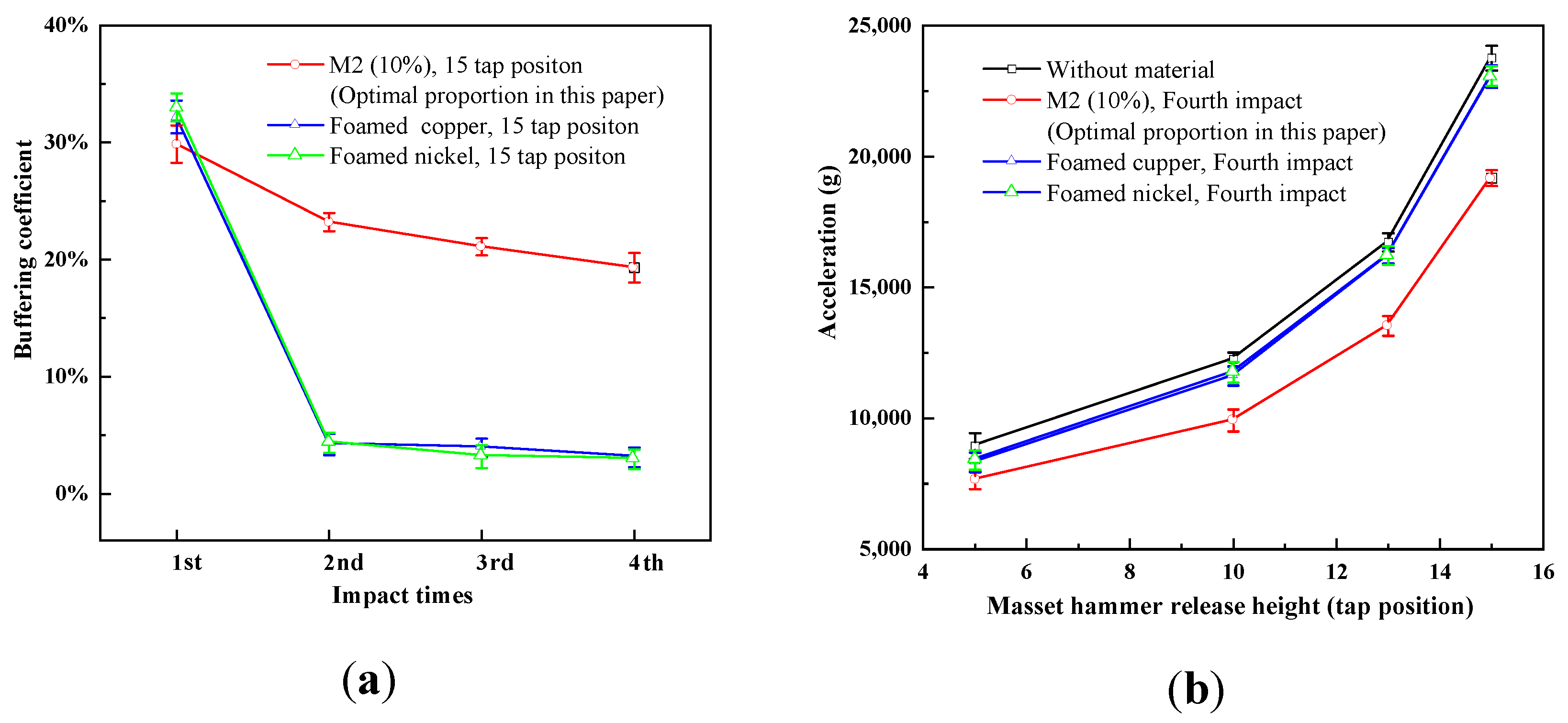
17]. More specifically, the energy absorption characteristics of M2 (10%) are compared with those of the EPDM rubber during the multi-impact process with overloads of different amplitudes, which are realized by changing the release height of the hammer rod. Four cases with 5, 10, 13, and 15 tap positions are conducted, respectively; the average peak of each height is determined through multiple tests. Figure 6a presents the impact peak values corresponding to different tap positions during the first impact process. In Figure 6a, the unbuffered peak values of the release heights for 5, 10, 13, and 15 tap positions are 8937 g, 12,250 g, 16,723 g, and 23,766 g, respectively. After buffered by M2 (10%), the peak values decrease to 7163 g, 8907 g, 11,815 g, and 16,670 g, and the buffering coefficients become 19.8%, 27.3%, 29.3%, and 29.8%, respectively. However, after buffered by the EPDM rubber, the peak values decrease to 7608 g, 10,360 g, 14,060 g, and 19,510 g, and the buffering coefficients become 14.87%, 15.4%, 15.9%, and 17.9%, respectively. Clearly, the buffering coefficient of the EPDM is lower than that of M2 (10%) during the first impact process of the same height. Figure 6b presents impact peak values corresponding to different tap positions during the fourth impact process. According to the figure, the buffering coefficient of M2 (10%) is still higher than that of the EPDM in the fourth impact process. Clearly, although the rubber is very elastic, its energy absorption characteristics are inferior to those of the composite material M2 (10%).
The comparative trials of traditional porous materials, foamed copper (Longshengbao Electronic Material Co., Ltd., Kunshan, China; porosity 98%; 0.275 g / cm 3 ) and foamed nickel (Longshengbao Electronic Material Co., Ltd., Kunshan, China; porosity 98%; 0.25 g / cm 3 ), are also conducted in this paper, and the results are shown in Figure 7. According to Figure 7a, at the release height for 15 tap position, the buffering coefficients of foamed copper and foamed nickel are better than those of M2 (10%) during the first impact process. However, with the increase of the impact times, the buffering coefficients of foamed copper and foamed nickel decrease evidently. Additionally, the energy absorption capacities are inferior to those of the composite material M2 (10%) in the second, third and fourth impact process. Figure 7b presents the impact peak values corresponding to different tap positions during the fourth impact process. It is reflected, in the figure, that peak values buffered by foamed copper and foamed nickel are larger than those buffered by M2 (10%) in the fourth impact process. Evidently, traditional porous materials are suitable for single impact process, rather than multi-impact process. As well, the energy absorption capacities of M2 (10%) are superior to the traditional porous materials in multi-impact process.
In conclusion, in the multi-impact process, the energy absorption characteristics of M2 (10%) are better than those of the polymer and traditional porous materials under the same impact conditions.

3.2. Recoverability Analysis: Polymer Fiber Network Enhances Elasticity

To analyze the recoverability of the composite materials during multi-impact processes, the electronic universal material testing machine (Changchun Testing Institute; CSS-44100) is used for quasi-static compression mechanical tests. The test results are shown in Figure 8, and the thickness of the samples before and after loading is listed in Table 3. The mass of the aluminum structure (including the sensor) is 56 g, and the size is Φ 28 × 20.5   mm 
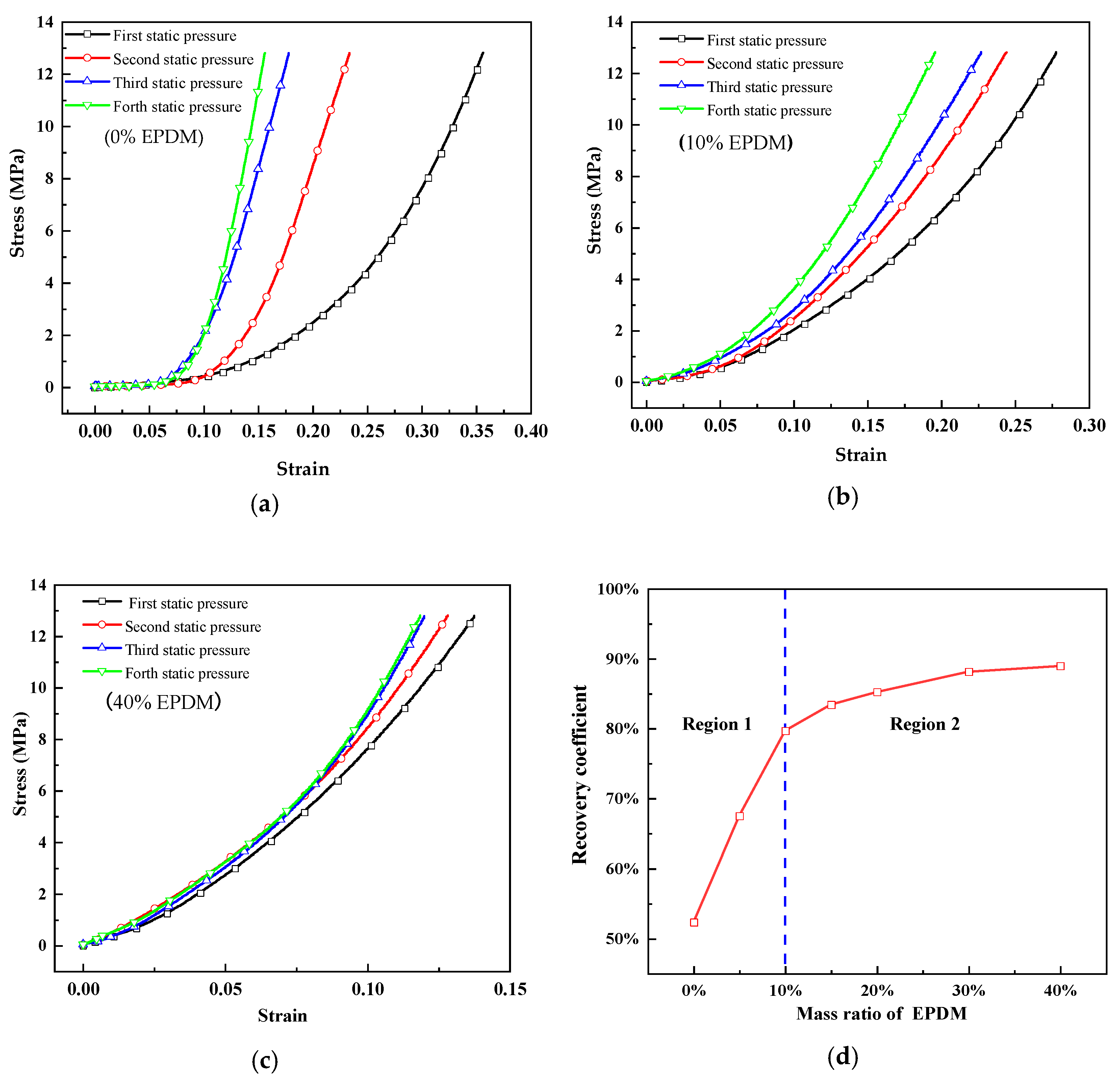
. By considering that the peak acceleration without any buffering material is 23,766 g, the resulting peak stress transferred from the bottom of the test device to the aluminum structure is 12.81 MPa. Hence, the peak stress applied to the test material is 12.81 MPa (the loss in the delivery process is not considered). 12.81 MPa is chosen as the upper limit in the quasi-static compression mechanical tests, and the strain corresponding to 12.81 MPa is used as a reference to represent the characteristics of the test materials in the quasi-static compression process.
Figure 8a–c show the stress-strain curves of M0 (0%), M2 (10%), and M6 (40%) of the loading experiments consisting of four steps, respectively. According to Figure 8a, with increasing number of loading times, the strain decreases gradually under equal stress. It means that compressibility of the same sample under the same stress in multiple loadings decreases, thereby indicating that the material experiences a plastic deformation during the loading process. It is in accord with the thickness change in Table 3 that M0 (0%) has undergone plastic deformation. As a result, the energy absorption capacity of the plastic deformation decreases gradually. According to Figure 8b,c, the strain decreases with a different attenuation ratio under the same stress, with increasing mass ratio of the EPDM rubber. Clearly, the EPDM rubber improves the elasticity and recovery characteristics of the material, which is consistent with the thickness change in Table 3. To characterize the recovery performance of the test materials in a multi-impact process, the recovery coefficient β is defined:
β = ε 2 ε 1 · ε 3 ε 1 · ε 4 ε 1 3
where ε is the strain corresponding to 12.81MPa stress and ε i / ε 1 the recovery rate of the strain of the i th load relative to the strain of the first load. The larger the recovery coefficient β , the better the restorability of the material.
Figure 8d presents the relationship between the recovery coefficient of the multiple loadings and the EPDM rubber proportion. As shown in Region 1, when the mass ratio of the EPDM rubber is less than 10%, the recovery coefficients of the samples increase rapidly with increasing EPDM rubber content. Hence, the restorability of the composite material improves clearly by the addition of EPDM rubber during the multiple loading processes, which is consistent with the result that the attenuation coefficient of the multi-impact decreases rapidly with increasing EPDM content. Furthermore, the buffering performances of the composite materials improve with increasing EPDM content. When the mass ratio of the EPDM rubber is over 10%, the recovery coefficients of the samples increase slowly and tend to stabilize. This result is consistent with the result that the attenuation coefficient decreases slightly and the decrease in the buffering coefficient is small during the multi-impact process for an EPDM rubber mass ratio of over 10%.
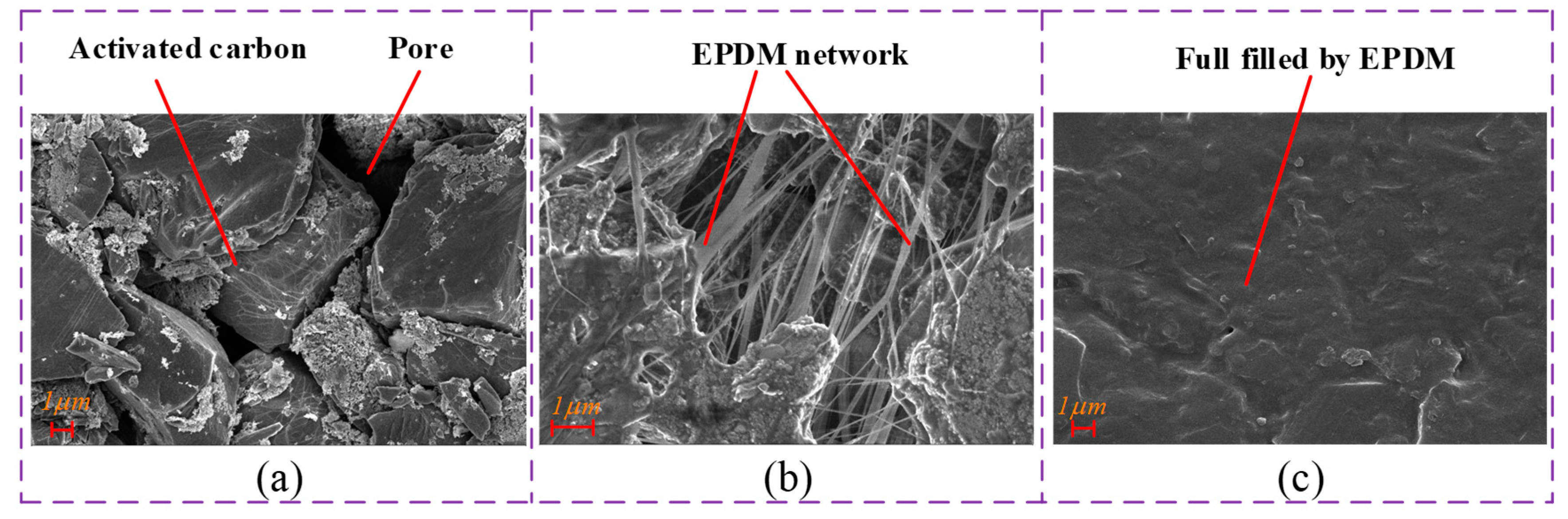
To study the effect of the microstructure on the restorability, three typical samples, M0 (without EPDM rubber), M2 (10% EPDM rubber), and M6 (40% EPDM rubber), are selected for the scanning electron microscopy (SEM) tests. Figure 9a presents the SEM image of M0 (0%). Clearly, the activated carbon film is a porous material composed of activated carbon particles and pores in the microscopic state. The pores are clearly visible at 10 , 000 × magnification and will be compressed and deformed during an impact process. Figure 9b presents the SEM image of the M2 (10%) sample. The added EPDM rubber exists in the form of fibers under the action of a shearing force, and the activated carbon particles are connected to each other by the EPDM rubber fiber, thereby forming a micro-network envelope structure. This structure will lead to an increase in the elastic ability of the composite material based on the plastic deformation ability. Hence, M2 can exhibit a better buffering effect in the multi-impact process. First, the SEM image verifies that the composite of the activated carbon and EPDM rubber exhibits the characteristics of the proposed structure. Second, it explains the reason of the improvement of the recovery coefficient. Moreover, Figure 9c shows the SEM image of M6 (40%). When the mass ratio of the EPDM rubber reaches 40%, the activated carbon particles are completely covered by rubber, and the pores are filled up with rubber. The pores are barely visible at 10 , 000 × magnification. In addition, the elastic deformation capacity is greatly improved. Therefore, the attenuation coefficient of M6 (40%) changes slightly during the multi-impact process.
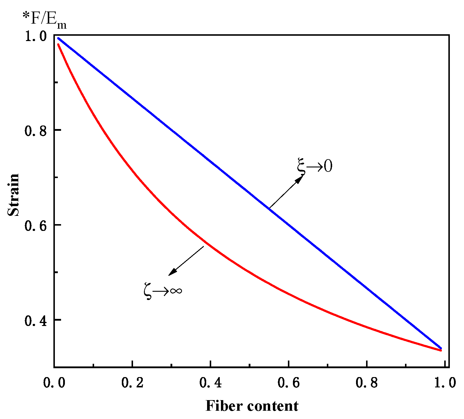
As the EPDM network exhibits a fiber structure, the elasticity modulus can be determined based on an empirical equation proposed in [32,33,34,35].
E E m = 1 + ξ η φ f 1 η φ f
η = ( E f / E m ) 1 ( E f / E m ) + ξ .
Here, E represents the elasticity modulus of the composite material; E m the elasticity modulus of the pure activated carbon film; E f the elasticity modulus of the fiber; ξ a non-negative value, which represents the fiber reinforcement effect and depends on the geometry, arrangement, and loading conditions of the fibers; and φ f is the fiber volume fraction.
For ξ = 0 :
η = 1 E m E f .
Therefore, Equation (4) becomes:
1 E = φ f E f + 1 φ f E m .
The strain ε can be determined as follows:
ε = F E = F ( φ f E f + 1 φ f E m ) .
When ξ , η 0 :
ξ η = E f E m 1
and
E = E f φ f + E m ( 1 φ f ) .
Consequently, the strain ε is expressed as follows:
ε = F E = F ( 1 E f φ f + E m ( 1 φ f ) ) .
Based on the quasi-static compression mechanical test, E m = 29 MP a and E f = 78 MP a . The upper and lower limits of the strain variations with respect to the fiber content are shown in Figure 10. With increasing rubber fiber content, the strain decreases under equal force. The smaller the strain, the less plastic deformation occurs. Therefore, the rubber fiber improves the restorability of the material.
In summary, according to the quasi-static compression mechanical tests and SEM results, adding EPDM rubber into activated carbon can improve its recoverability during multi-impact processes. According to Figure 8d, when the EPDM rubber proportion is less than 10%, the recoverability improves quickly. When the EPDM rubber proportion is over 10%, the recoverability improves slowly.

3.3. Energy Absorption Analysis: Small-Scale Pores Contribute Most to the Buffering Ability

The porosity analysis tests are conducted with a mercury porosimeter analyzer (Quantachrome Instrument; Poremaster GT60) to analyze the influence of the internal microstructure of the composite material on the energy absorption characteristics. The results are shown in 
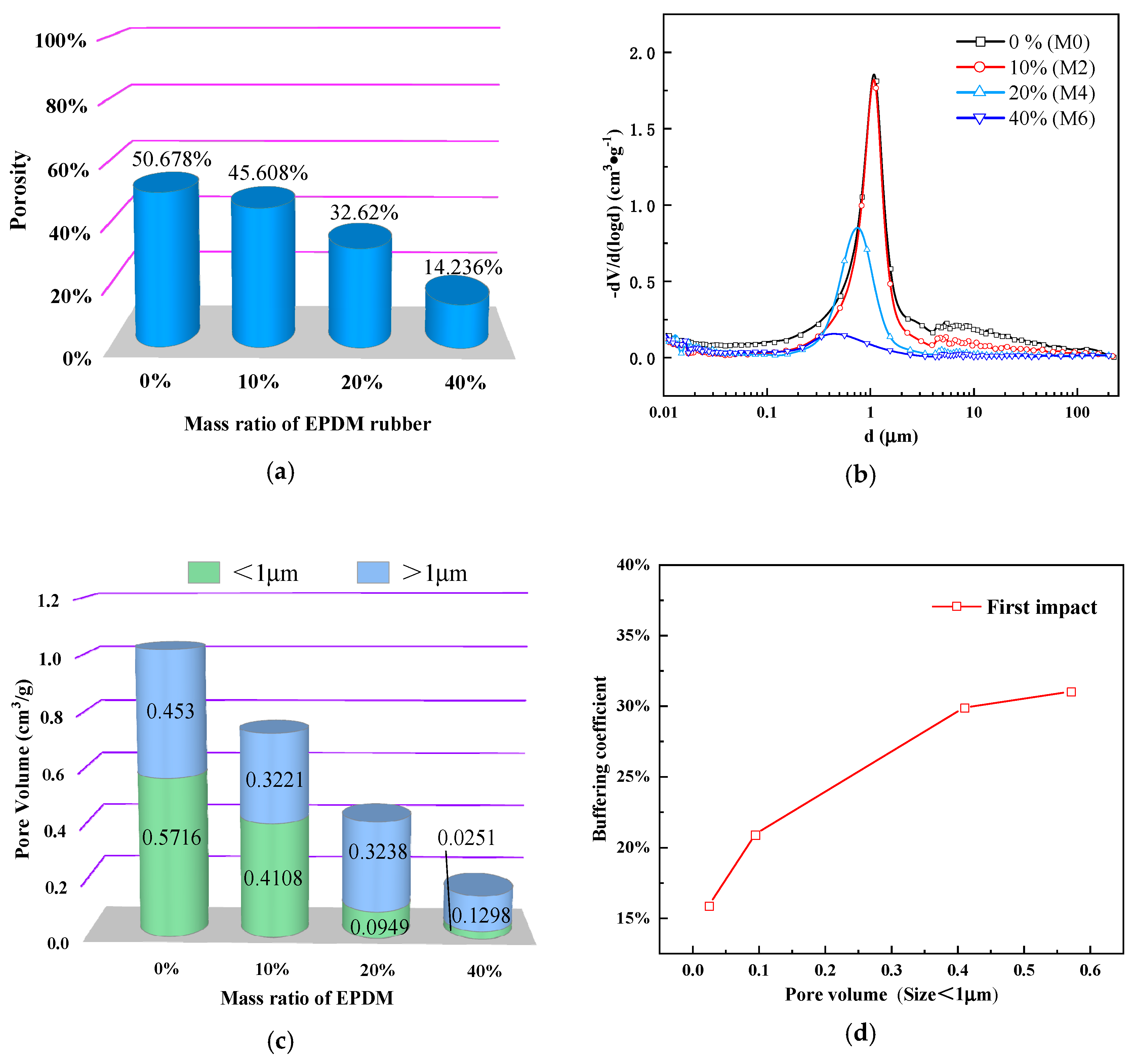
Figure 11. According to Figure 11a, the porosities of the four samples M0 (0%), M2 (10%), M4 (20%), and M6 (40%) are 50.678%, 45.608%, 32.62%, and 14.236%, respectively. Hence, the inner pores can be compressed during the impact process in order to reduce the overload acting on the protected parts and realize the buffering effect. In addition, the energy absorption characteristics are closely related to the porosity. The higher the porosity, the stronger are the energy absorption characteristics. According to the overall trend, the porosity of the samples decreases with increasing EPDM rubber proportion, which is consistent with the result that the buffering coefficient of the single impact process decreases gradually in Figure 5b. The porosity volume of the pure activated carbon film (M0 (0%)) is larger than the half sample volume, which is consistent with the fact (Figure 9a) that the pure activated carbon film consists of activated carbon particles and many pores. When the EPDM rubber proportion increases to 40%, the porosity decreases sharply. This is reflected in Figure 9c, in which the pores are barely visible at 10 , 000 × magnification. Regarding the local change trend, compared with that of M0 (0%), although the EPDM mass ratio of M2 (10%) is increased by 10%, the porosity decreases only by 5.07%. By contrast, the porosity of M4 (20%) decreases by 12.988% with respect to that of M2 (10%), despite the 10% mass ratio increase of EPDM rubber. This is consistent with the result that the buffering coefficient of M2 (10%) decreases slightly compared with that of M0 (0%), whereas the buffering coefficient of M4 (20%) decreases dramatically compared with that of M2 (10%) during the single impact process.
The pore size distributions of the four test samples are shown in Figure 11b. The x-axis represents the pore diameter ( μ m ; logarithmic form). Based on the large pore size span, the y-axis is the differential of the logarithm of the pore volume with respect to the pore diameter ( c m 3 / g ), according to the BJH algorithm. Furthermore, the pore sizes of the samples decrease with increasing EPDM rubber proportion, in particular for M4 (20%) and M6 (40%). The pore size distribution of M2 (10%) is similar to that of M0 (0%), whereas the pore size distributions of M4 (20%) and M6 (40%) are quite different from that of M0. By integrating the pore size distribution of each sample, the pore volume is divided into two parts by taking the pore size 1 μ m as the limit, as shown in Figure 11c. This step is necessary for analyzing the effect of the increasing EPDM proportion on the pore size of the activated carbon film.
According to Figure 11c, compared with that of M0 (0%), the reduction (0.1608 mL / g ) in the small-scale pore volume (size < 1 μ m ) of M2 (10%) is slightly higher than the reduction (0.1309 mL / g ) in the large-scale pore volume (size > 1 μ m ). However, the large-scale pore volume (size > 1 μ m ) of M4 (20%) basically does not change compared with that of M2 (10%), whereas the small-scale pore volume (size < 1 μ m ) of M4 (20%) decreases greatly, from 0.4108 to 0.0949 mL / g . With the addition of an excessive amount of EPDM rubber, the large-scale pore volume (size > 1 μ m ) of M6 (40%) decreases greatly, whereas the small-scale pore volume (size < 1 μ m ) decreases slightly compared with that of M4 (20%). According to the previously presented analysis, the pores (size < 1 μ m ) are preferentially filled. Based on these and the impact results, the small-scale pore volume (size < 1 μ m ) has a great influence on the buffering coefficient. The relationship between the small-scale pore volume (size < 1 μ m ) and buffering rate is shown in Figure 11d; the energy absorption characteristics of the samples become deteriorated with decreasing small-scale pore volume (size < 1 μ m ). When a shock overload propagates through the material in the form of a stress wave, the porous material attenuates principally the stress wave owing to friction, vibration, and irregular reflections at the abundant internal material [36,37]. Based on the specific material structure and different application environments, various mechanisms have influences of different degrees. When the stress wave propagates through the internal structure of the composite material, it causes the vibration of the activated carbon particles and a mutual friction between the pore wall and inner air. In addition, the stress wave bounces continuously off the pore surface and causes an elastic collision when reflected at the pore wall of the porous material. A stress wave with a relatively high energy may even cause an inelastic collision owing to its high amplitude, thereby causing a plastic deformation and a relatively high energy loss. The kinetic energy is converted into other forms, such as deformation energy and heat energy. Thus, the pore surface area is an important influencing factor. Considering the large and small-scale pores in equal volumes, it is assumed that the shape of the pores inside the porous material is spherical in the ideal state. Thus, the surface area S and volume V of the large-scale pore with radius R can be expressed as follows:
{ V = 4 π R 3 3 S = 4 π R 2 .
By assuming that the volume of the n small-scale pores is the same as the volume of one large-scale pore, the volume V 1 of the small-scale pore becomes:
V 1 = 4 π R 3 3 n .
The radius r of the small-scale pore is expressed as follows:
r = R 3 n 3
and the surface area S 1 of the small-scale pore is expressed as follows:
S 1 = 4 π r 2 = 4 π ( 1 n 3 ) 2 R 2 .
The ratio of the sum of the surface areas of n small-scale pores to the surface areas of the larger pore is defined as follows:
τ = n S 1 S = n ( 1 n 3 ) 2 = n ( n 3 ) 2 .
Clearly, τ is above 1 and increases with increasing n . Therefore, the contact areas between the small-scale pores and activated carbon particles are larger than those of the large-scale pores. As a result, mutual friction is more likely between the small-scale pore wall and inner air. In addition, reflections at the pore wall of the porous material are more likely, and the small-scale pores absorb energy more easily.
The hardness tests are carried out in this paper. Two kinds of shore durometers, LX-A and LX-D (Nanjing Suce Measuring Instruments Co., Ltd., Nanjing, China), are used for different hardness. The tests are conducted based on the shore durometer method. As the recommended measurement interval of shore durometers is 20-90HA and 20-90HD, LX-A is used to measure M0 (0%), M1 (5%), M2 (10%), while LX-A is used to measure M3 (15%), M4 (20%), M5 (30%), M6 (40%). As shown in Table 4, with the increasing EPDM proportion, the hardness of the composite materials increases. It is consistent with the reduction of the porosity. Additionally, it is known that the impact resistance increases with the increasing hardness of the materials, which will result in less deformation. As a result, energy absorption characteristics by deformation also decrease. The Hardness test results are consistent with the results in Figure 5b.
In summary, the porosity of the test material has a great influence on the energy absorption characteristics of the samples, particularly the pore volume (size < 1 μ m ). When the mass ratio of the EPDM rubber increases, the porosity of the sample and pore diameter decreases, thereby leading to an increase of the hardness and a decrease in the energy absorption and deteriorated buffering characteristics of the sample. When the mass ratio of the EPDM rubber is 10%, the porosity of the sample decreases slightly. However, when the mass ratio of the EPDM rubber is over 20%, the excessive rubber amount reduces the porosity of the sample greatly.

4. Conclusions

This paper presents a novel energy absorption method based on elastic polymer-modified porous material. The composite made from porous activated carbon and EPDM rubber fiber is studied as an example to verify the feasibility of this structure. According to the experiments, the proposed material exhibits both an excellent energy absorption and restorability performance in the multi-impact process, and the optimal mass ratio of the EPDM rubber is found to be 10%. In addition, the quasi-static compression mechanical tests and SEM results reveal that the microscopic elastic fiber network, formed by the elastic polymer, is crucial for the recoverability of the composite material. According to the analysis, a 10% mass ratio of the elastic polymer is sufficient for upgrading the recoverability performance of the composite material to the level of a pure polymer. Regarding the energy absorption performance, the porosity analysis tests and theoretical results reveal the dominant contribution of small pores (size < 1 μ m ). As the polymer tends to fill preferentially small pores, a 10% mass ratio of the polymer has a slightly negative effect on the volume of the small pores, but the effect is very slight and the energy absorption characteristics of the composite are close to those of the pure porous material. To conclude, the proposed material design provides a theoretical and design basis for protecting electronic devices and systems in narrow spaces from extreme damage caused by multiple mechanical impact.

Supplementary Materials

The following are available online at https://www.mdpi.com/2076-3417/10/1/110/s1, Figure S1: Maximum tension of test materials containing different proportions of EPDM, Figure S2: (a)-(g) Impact curves buffered by M0-M6 recorded by acceleration sensors.

Author Contributions

J.Z. and K.D. conceived and designed the experiments; J.Z., D.Y. and B.Y. performed the experiments; J.Z. and K.D. analyzed the data; X.W., H.Z. and Z.Y. contributed analysis tools; J.Z. wrote the paper. All authors have read and agreed to the published version of the manuscript.

Funding

This research was funded in part by Key Basic Research Projects of Basic Strengthening Plan of China (Grant number 2017-JCJQ-ZD-004), and in part by the Natural Science Foundation of Jiangsu Province under Grant (BK20190470).

Conflicts of Interest

The authors declare no conflict of interest.

References

  1. Li, R.; Chen, K.; Kan, X.G.; Shi, K. Hard target Smart Fuze Detonating Control Summary. J. Detect. Control 2010, 6, 1–4. [Google Scholar]
  2. You, J.C.; Li, D.J.; Ou, Y.K.; Zhao, H. Precise detonating-control technique for hard-target penetration fuze. J. Chin. Inert. Tech. 2016, 24, 114–118. [Google Scholar]
  3. Li, Q.M.; Chen, X.W. Dimensionless formulae for penetration depth of concrete target impacted by a non-deformable projectile. Int. J. Impact Eng. 2003, 28, 93–116. [Google Scholar] [CrossRef]
  4. Zhang, H.; Dai, K.R.; Yin, Q. Ammunition Reliability against the Harsh Environments During the Launch of an Electromagnetic Gun: A Review. IEEE Access 2019, 7, 45322–45339. [Google Scholar] [CrossRef]
  5. Arcondoulis, E.J.; Liu, Y.; Li, Z.; Yang, Y.; Wang, Y. Structured Porous Material Design for Passive Flow and Noise Control of Cylinders in Uniform Flow. Materials 2019, 12, 2905. [Google Scholar] [CrossRef]
  6. Yi, F.; Zhu, Z.; Hu, S.; Yi, P.; He, L.; Ning, T. Dynamic compressive behavior of aluminum alloy foams. J. Mater. Sci. Lett. 2001, 20, 1667–1668. [Google Scholar] [CrossRef]
  7. Wen, C.E.; Yamada, Y.; Shimojima, K.; Chino, Y.; Hosokawa, H.; Mabuchi, M. Compressibility of porous magnesium foam: dependency on porosity and pore size. Mater. Lett. 2004, 58, 357–360. [Google Scholar] [CrossRef]
  8. Wang, J.; Wang, N.; Liu, X.; Ding, J.; Xia, X.; Chen, X.; Zhao, W. Compressive deformation behavior of closed-cell micro-pore magnesium composite foam. Materials 2018, 11, 731. [Google Scholar] [CrossRef] [Green Version]
  9. Orbulov, I.N.; Májlinger, K. Description of the compressive response of metal matrix syntactic foams. Mater. Des. 2013, 49, 1–9. [Google Scholar] [CrossRef]
  10. Wang, P.; Xu, S.; Li, Z.; Yang, J.; Zhang, C.; Zheng, H.; Hu, S. Experimental investigation on the strain-rate effect and inertia effect of closed-cell aluminum foam subjected to dynamic loading. Mat. Sci. Eng. A-Struct. 2015, 620, 253–261. [Google Scholar] [CrossRef]
  11. Islam, M.A.; Brown, A.D.; Hazell, P.J.; Kader, M.A.; Escobedo, J.P.; Saadatfar, M.; Xu, S.; Ruan, D.; Turner, M. Mechanical response and dynamic deformation mechanisms of closed-cell aluminium alloy foams under dynamic loading. Int. J. Impact. Eng. 2018, 114, 111–122. [Google Scholar] [CrossRef]
  12. Talebi, S.; Sadighi, M.; Aghdam, M.M. Numerical and experimental analysis of the closed-cell aluminium foam under low velocity impact using computerized tomography technique. Acta Mech. Sin. 2019, 35, 144–155. [Google Scholar] [CrossRef]
  13. Petel, O.E.; Ouellet, S.; Frost, D.L.; Higgins, A.J. Shock Hugoniot measurements in foam. J. Phys. Conf. Ser. 2014, 500, 112050. [Google Scholar] [CrossRef]
  14. Mines, R.A.W.; Roach, A.M.; Jones, N. High velocity perforation behaviour of polymer composite laminates. Int. J. Impact Eng. 1999, 22, 561–588. [Google Scholar] [CrossRef]
  15. Liu, H.; Cao, Z.K.; Luo, H.J.; Shi, J.C.; Yao, G.C.; Liu, H. Performance of closed-cell aluminum foams subjected to impact loading. Mat. Sci. Eng. C-Mater. 2013, 570, 27–31. [Google Scholar] [CrossRef]
  16. Goff, J.; Sulaiman, S.; Arkles, B.; Lewicki, J.P. Soft materials with recoverable shape factors from extreme distortion states. Adv. Mater. 2016, 28, 2393–2398. [Google Scholar] [CrossRef]
  17. Gamlin, C.D.; Dutta, N.K.; Choudhury, N.R. Mechanism and kinetics of the isothermal thermodegradation of ethylene-propylene-diene (EPDM) elastomers. Polym. Degrad. Stabil. 2003, 80, 525–531. [Google Scholar] [CrossRef]
  18. Chen, X.Q.; Shen, Z.P.; He, Q.S.; Du, Q.; Liu, X.E. Influence of uncertainty and excitation amplitude on the vibration characteristics of rubber isolators. J. Sound Vib. 2016, 377, 216–225. [Google Scholar]
  19. Balasubramanian, P.; Ferrari, G.; Amabili, M. Identification of the viscoelastic response and nonlinear damping of a rubber plate in nonlinear vibration regime. Mech. Syst. Signal. Process. 2018, 111, 376–398. [Google Scholar] [CrossRef]
  20. Alsakarneh, A.; Moore, L.; Barrett, J. Evaluation of the use of a rubber buffer layer to protect embedded SIP devices from high mechanical forces. In Proceedings of the IEEE 61st Electronic Components and Technology Conference, Lake Buena Vista, FL, USA, 31 May–3 June 2011. [Google Scholar]
  21. Lötters, J.C.; Olthuis, W.; Veltink, P.H.; Bergveld, P. The mechanical properties of the rubber elastic polymer polydimethylsiloxane for sensor applications. J. Micromech. Microeng. 1997, 7, 145. [Google Scholar] [CrossRef]
  22. Lee, J.Y.; Kumar, V.; Tang, X.W.; Lee, D.J. Mechanical and electrical behavior of rubber nanocomposites under static and cyclic strain. Compos. Sci. Technol. 2017, 142, 1–9. [Google Scholar]
  23. Geethamma, V.G.; Kalaprasad, G.; Groeninckx, G.; Thomas, S. Dynamic mechanical behavior of short coir fiber reinforced natural rubber composites. Compos. Part A-Appl. Sci. 2005, 36, 1499–1506. [Google Scholar] [CrossRef]
  24. Wang, Z.; Volinsky, A.A.; Gallant, N.D. Nanoindentation study of polydimethylsiloxane elastic modulus using Berkovich and flat punch tips. J. Appl. Polym. Sci. 2015, 132. [Google Scholar] [CrossRef] [Green Version]
  25. Wen, L.Q.; Lu, J.X.; Zhang, T.L. The simulation comparison on the anti-shock capacity of foam aluminum and rubber for testing equipment. J. Project. Guid. 2010, 30, 223–225. [Google Scholar]
  26. Dai, K.R.; Wang, X.F.; You, Z.; Zhang, H. Pressure sensitivity enhancement of porous carbon electrode and its application in self-powered mechanical sensors. Micromachine 2019, 10, 58. [Google Scholar] [CrossRef] [Green Version]
  27. Dai, K.R.; Wang, X.F.; Li, R.; Zhang, H.; You, Z. Theoretical study and applications of self-sensing supercapacitors under extreme mechanical effects. Extreme Mech. Lett. 2019, 26, 53–60. [Google Scholar] [CrossRef]
  28. Dai, K.R.; Wang, X.F.; Yi, F.; Yin, Y.; Jiang, C.; Niu, S.; Li, Q.; You, Z. Discharge voltage behavior of electric double-layer capacitors during high-g impact and their application to autonomously sensing high-g accelerometers. Nano Res. 2018, 11, 1146–1156. [Google Scholar] [CrossRef]
  29. Takemura, D.; Mitsuda, K.; Mitani, T.; Kubo, K. Eletric Double-Layer Capacitor. U.S. Patent US20080112112, 15 May 2008. [Google Scholar]
  30. Jing, P. High-g Impact Test Value of the Research of Key Technologies. Master’s Thesis, North University of China, Taiyuan, China, 2009. [Google Scholar]
  31. Zhang, J.M.; Zhang, H.; Yu, D. Design of Ultra-High g Penetration Fuze Data Record Device. In Proceedings of the IEEE 4th International Conference on Control Science and Systems Engineering, Wuhan, China, 21–23 August 2018. [Google Scholar]
  32. Scida, D.; Aboura, Z.; Benzeggagh, M.L.; Bocherens, E. A micromechanics model for 3D elasticity and failure of woven-fibre composite materials. Compos. Sci. Technol. 1991, 59, 505–517. [Google Scholar] [CrossRef]
  33. Jiao, G.Q.; Jia, P.R. Mechanics of Composite Materials; Northwestern polytechnical university press: Xian, China, 2008; pp. 142–143. [Google Scholar]
  34. López-Alba, E.; Schmeer, S.; Díaz, F. Energy absorption capacity in natural fiber reinforcement composites structures. Materials 2018, 11, 418. [Google Scholar] [CrossRef] [Green Version]
  35. McBride, A.K.; Turek, S.L.; Zaghi, A.E.; Burke, K.A. Mechanical behavior of hybrid glass/steel fiber reinforced epoxy composites. Polymers 2017, 9, 151. [Google Scholar] [CrossRef] [Green Version]
  36. Liu, P.S.; Qing, H.B.; Hou, H.L. Primary investigation on sound absorption performance of highly porous titanium foams. Mater. Des. 2015, 85, 275–281. [Google Scholar] [CrossRef]
  37. Karami, B.; Shahsavari, D.; Janghorban, M.; Dimitri, R.; Tornabene, F. Wave propagation of porous nanoshells. Nanomaterials 2019, 9, 22. [Google Scholar] [CrossRef] [PubMed] [Green Version]
Figure 1. Application of energy absorption material under multiple extreme mechanical impacts: (a) Process of multi-impact in military application; (b) Installation of buffering material and protected part; (c) Continuous collision between cars.
Applsci 10 00110 g001
Figure 2. Schematic diagram of microscale structure change.
Applsci 10 00110 g002
Figure 3. Schematic diagram of material preparation.
Applsci 10 00110 g003
Figure 4. (a) Machete hammer test schematic diagram; (b) Structure drawing of the test device.
Applsci 10 00110 g004
Figure 5. (a) Impact curves under different conditions recorded by acceleration sensors; (b) Buffering coefficients in single impact process; (c) Comparison of buffering coefficients in multi-impact process; (d) Comparison of attenuation coefficients in multi-impact process.
Applsci 10 00110 g005
Figure 6. (a) Impact peaks corresponding to different tap positions during first impact process; (b) Impact peaks corresponding to different tap positions during fourth impact process.
Applsci 10 00110 g006
Figure 7. (a) Buffering coefficient of M2 (10%), foamed copper and foamed nickel at 15 tap position during four times of impact process; (b) Impact peaks corresponding to different tap positions during fourth impact process.
Applsci 10 00110 g007
Figure 8. (ac) Stress–strain curves of M0 (0%), M2 (10%), and M6 (40%) during four loading steps, respectively; (d) Relationship between recovery rate of multiple loadings and mass ratio of EPDM rubber.
Applsci 10 00110 g008
Figure 9. (ac) SEM images of pure activated carbon film, activated carbon film containing 10% EPDM rubber, and activated carbon film containing 40% EPDM rubber, respectively.
Applsci 10 00110 g009
Figure 10. Strain of composite varies with the content of rubber fiber.
Applsci 10 00110 g010
Figure 11. (a) Porosity of test materials containing different mass ratios of EPDM rubber; (b) Pore size distribution; (c) Pore volumes of test materials containing different proportions of EPDM; (d) Relationship between buffering ratio and pore volume (size < 1 μ m ).
Applsci 10 00110 g011
Table 1. Samples of different mass ratio of EPDM (Ethylene-Propylene-Diene Monomer) rubber.
SampleMass/gMass Ratio of EPDM
Activated Carbon FilmEPDM Rubber
M06000%
M16035%
M260610%
M360915%
M4601220%
M5601830%
M6602440%
Table 2. Buffering coefficients and attenuation coefficients of different samples.
Sample N 1 N 4 α 4 1
M031.01%10.78%65.2%
M130.79%15.96%48.2%
M229.86%19.30%35.4%
M321.91%17.02%22.3%
M420.88%16.72%19.9%
M520.14%16.47%18.2%
M615.85%15.4%2.8%
Table 3. The thickness of the samples before and after loading.
SamplesBefore Loading (mm)After First Loading (mm)After Second Loading (mm)After Third Loading (mm)After Fourth Loading (mm)
M0 (0%)2.081.711.571.441.41
M1 (5%)1.941.71.61.571.51
M2 (10%)1.921.721.641.531.49
M3 (15%)1.951.81.711.671.64
M4 (20%)1.981.91.831.81.76
M5 (30%)2.052.012.011.981.96
M6 (40%)2.062.032.022.022.01
Table 4. Hardness test results.
SampleShore A (HA)Shore D (HD)
M0 (0%)41.2/
M1 (5%)57.4/
M2 (10%)66.8<20
M3 (15%)>9027.4
M4 (20%)>9033.8
M5 (30%)>9039.6
M6 (40%)>9043.2

