Article

Seismic Imaging of Seafloor Deformation Induced by Impact from Large Submarine Landslide Blocks, Offshore Oregon

1
School of Earth Sciences, The Ohio State University, Columbus, OH 43210, USA
2
ASEE Postdoctoral Research Fellow, US Naval Research Laboratory, Stennis Space Center, Washington, DC 20375, USA
3
College of Earth, Ocean, and Atmospheric Sciences, Oregon State University, Corvallis, OR 97331, USA
4
Department of Coastal and Marine Systems Science, Coastal Carolina University, Conway, SC 29528, USA
*
Author to whom correspondence should be addressed.
Geosciences 2019, 9(1), 10; https://doi.org/10.3390/geosciences9010010
Submission received: 13 November 2018 / Revised: 17 December 2018 / Accepted: 19 December 2018 / Published: 25 December 2018
(This article belongs to the Special Issue Submarine Landslides – Assessing the Stability of Submerged Slopes)

Abstract

:
A series of large blocks from the 44-North Slide, offshore Oregon, impacted the seafloor with sufficient force to induce a broad zone of deformation. In 2017, we acquired a seismic profile from the headwall area to the outer toe of this slide. Previous work identified this slide, but it has not been imaged at high resolution before this survey. A striking surficial feature is a collection of blocks that lie downslope from an amphitheater-shaped headwall. The blocks traveled up to 20-km horizontally and about 1200-m vertically down a 13° slope and now cover an area of ~100 km2. The blocks have rough and angular edges that extend up to 400-m above the surrounding seafloor. Seaward of the blocks, a 10-km zone of sediment is deformed, horizontally shortened by 8%. We interpret the strain field to be a result of the dynamic impact forces of the slide. This suggests a high-mobility failure with tsunamigenic potential. It is unclear what preconditioned and triggered this event, however, earthquake-induced failure is one possibility. Gas hydrate dissociation may have also played a role due to the presence of a bottom-simulating reflector beneath the source area. This study underscores the need to understand the dynamic processes of submarine landslides to more accurately estimate their societal impacts.

1. Introduction

Submarine landslides have been known to cause tsunamis that can impact coasts around the world [1,2,3,4]. An example of this occurred during the 1964 great Alaska earthquake in Resurrection Bay, when a 1-km long section of waterfront failed, producing a 10-m wave that hit 30 min before the earthquake-induced wave, killing 13 people [5]. Multibeam bathymetry revealed a blocky debris field with individual blocks up to 10–15 m high [5]. Landslide generated tsunamis depend on landslide volume, length, thickness, initial acceleration, maximum velocity, water depth, and whether failure occurs in one or multiple stages. Sediments with higher strength often produce thicker cohesive landslides that generate larger tsunamis compared to sediments with lower strength [6,7,8,9]. This suggests that blocky slides may be more likely to produce a tsunami as opposed to disintegrative slides. Initial acceleration [10,11,12] and maximum velocity [13,14] may be the most important parameters that influence landslide generated tsunamis, but they are usually unknown and difficult to model.
The Cascadia margin offshore northern California to southern Canada is prone to geohazards, including earthquakes, volcanoes, tsunamis, and landslides. This is due largely to the active subduction of the Juan de Fuca Plate beneath the North American Plate (Figure 1A). Previous studies have shown that submarine landslides are common on this margin [8,15,16,17]. McAdoo et al. (2000) observed that the landslides in the southern Oregon margin are more dominantly blocky compared to the mostly disintegrative landslides in the north [16]. The largest blocky landslide on the Oregon margin, the 44-North slide [16], produced blocks up to 400-m high. These observations suggest that the southern Oregon margin may have a higher hazard potential due the blocky cohesive mode of slope failures. Peters et al. (2001) compiled paleotsunami deposits from more than 50 sites along the Cascadian margin. The sites in southern Oregon generally contained more tsunami deposits than elsewhere along the margin [18]. This could be the result of local tsunamis, which can be produced by submarine landslides; however, we recognize that tsunami deposits depend heavily on the depositional setting of the sites chosen and the local bathymetry.
Here, we use new high-resolution seismic reflection, bathymetry, core, and vane shear strength data to study the 44-North Slide. The seismic data reveals a 10-km long and 275-m thick zone of compressional deformation that surrounds the landslide blocks. We suggest that this deformation field was induced by the impact forces of the blocks. The blocky deposits were relatively strong since they retain their size and shape after travelling up to 20-km horizontally and 1200-m vertically down a 13° slope. This study proposes undrained loading pore pressure as the mechanism for the vertical extent of the deformation and supports McAdoo and Watts’ (2004) analysis that the southern Cascadia margin is more likely to produce tsunamigenic landslides, contributing to the hazard potential of the margin [8]. The shear strength data suggests that future landslide events may also be blocky in nature. This underscores the need to understand the dynamic processes of submarine landslides to more accurately estimate their societal impacts.

2. Materials and Methods

Reflection seismic data were collected offshore Oregon in 2017 (Figure 1) as part of the Early Career Seismic Chief Scientist Training Cruise 1718 aboard the R/V Roger Revelle using the Scripps Multichannel Seismic System. The seismic acquisition system consisted of a 600-m long active streamer with 48 channels recording shots at 25-m spacing from a 2 GI-gun cluster. The sampling rate was 0.5 ms and the recording length was 8.0 s, with a maximum fold of 12. This study only focuses on the eastern half of seismic line 15. The dominant frequency of the seismic line was ~100 Hz, which equates to a vertical resolution of approximately 3.75 m. The line was processed by applying an Ormsby bandpass and 15-25-350-500 Hz corner frequency filters, stacking by common depth points after normal move-out corrections, and then performing a frequency-wavenumber migration [23].
Interpretations were done using IHS Kingdom Suite software and examining available bathymetric data using the Global Multi-Resolution Topography (GMRT) database from http://www.geomapapp.org [21]. Horizontal strain was estimated by the ratio of change in length to the original length of the sediments deformed. The present day length was the length of the deformation zone as observed in the seismic data. The original length was estimated by using the path length in Adobe Illustrator after tracing mappable, seismic reflectors.
We integrated available core data from the following sources to enhance the interpretation of sedimentology and physical characteristics of the slope failure: Shallow piston cores collected within 5 km of seismic line 15 [22], core data from Deep Sea Drilling Project (DSDP) Leg 18 at Site 174 about 120-km northwest of seismic line 15 [19], and core and shear strength data from Ocean Drilling Program (ODP) Leg 146 at Site 892 that is about 74 km north of seismic line 15 [20]. The drill sites are located along strike and have similar depositional environments, therefore, we assumed that the sedimentology and physical properties did not significantly vary. The undrained shear strength of the top 100-m were compared against a global compilation to understand the relative strength of the sediments involved in the 44-North Slide (Figure 2) [24].
Calculations were performed for theoretical pore pressure developed immediately after the deposition of the landslide blocks assuming hydrostatic conditions prior to loading. Hydrostatic pressure (Ph), lithostatic stress (σv), and post-loading pore pressure (Ppost-load) were determined using the following equations:
P h =   ρ s w g z
σ v =   ρ s e d s g z s f + P h , s f
P p o s t l o a d =   ρ b l o c k s g h b l o c k s + P h
Where (g) is the gravitational acceleration, (ρsw) is the density of seawater, (ρseds) is the bulk density of the basin sediments, (ρblocks) is the bulk density of the landslide blocks, (z) is the depth below sea level, (zsf) is the depth below the seafloor, (Ph,sf) is the hydrostatic pressure at the seafloor, and (hblocks) is the average height of the landslide blocks. The density of seawater (ρsw) was assumed to be 1024 kg/m3. The bulk density for the basin sediments (ρseds) was chosen as 1800 kg/m3 from the physical properties measured from cores at Site 174 from DSDP Leg 18 [19]. The bulk density for the blocks (ρblocks) was an assumed value of 1850 kg/m3 based on previous work that shows mass movements are denser [25]. The average height of the blocks (hblocks) was 104-m, which was calculated by averaging the distance from the block peaks to the current seafloor.

3. Results

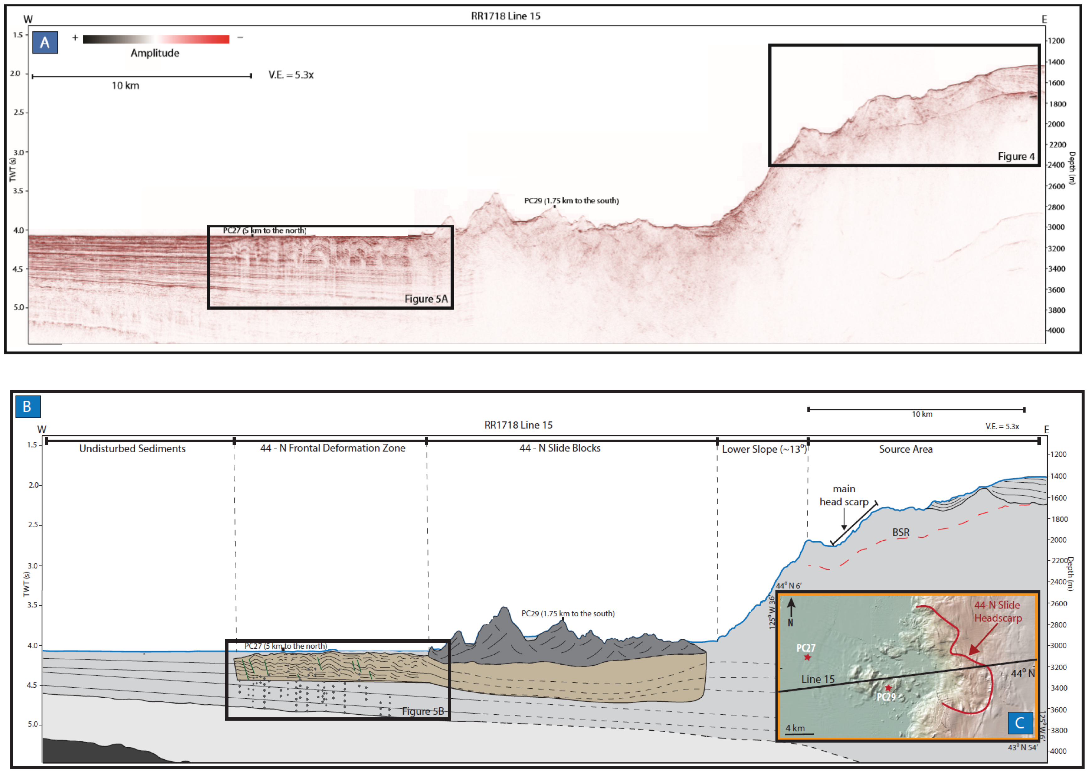
3.1. Landslide Characteristics and Seismic Geomorphology

The 44-North Slide main head scarp is visible in the available bathymetric data as well as the reflection seismic data (Figure 3 and Figure 4). It has a prominent amphitheater-shape and is very steep and tall, with a 22° slope and a 360-m height [16]. The landslide probably occurred over an expansive evacuation zone and likely had multiple smaller head scarps. The failed slope can be measured from bathymetric and seismic data at approximately 8° and the unfailed slope was about 13°. These measurements also agree with previous work done by McAdoo et al (2000) [16].
The landslide blocks were distributed within a 100 km2 area of the abyssal plain adjacent to the slope after travelling up to 20-km horizontally and 1200-m vertically down a 13° slope. The blocks are angular and rise up to 400-m high above the surrounding seafloor (Figure 3). The geometry of the blocks supports the interpretation that these blocks are cohesive and not a churned up mass movement. The reflection seismic characteristics of the blocks match that of the source area observed. The source area was observed as chaotic, discontinuous, low-amplitude reflectors in the reflection seismic data collected with some continuous stratigraphy visible (Figure 3 and Figure 4).
A striking feature observed in the reflection seismic data occurred immediately seaward of the 44-North slide blocks (Figure 3 and Figure 5). A 10-km long and 275-m thick zone of mostly parallel, continuous intervals of high and low amplitude reflectors appeared to be deformed. This deformed zone was horizontally shortened by 8%. A slip plane was observed at about a 3330-m depth (275 mbsf). Post-event sedimentary drape was observed as undeformed parallel continuous onlapping reflectors immediately above the deformation zone extending into the abyssal plane. Since only a two-dimensional profile was available and the deformation zone has been subsequently buried, it is difficult to determine how wide this deformation zone was. However, a subtle bumpy zone seaward of the blocks observed in the bathymetric data may be the bathymetric expression of the spatial limits of that zone.

3.2. Sedimentology and Physical Properties

Based on core data from ODP Leg 146 at Site 892 about 74-km north of the 44-North Slide, the source area, and therefore the blocks, consists of mostly firm clayey silt and silty clay [20]. The vane-shear strength data collected on ODP Leg 146 at Site 892 also show that the source sediments are relatively strong compared to other margins in the world (Figure 2) [20,24].
The abyssal plain sediments are fed by the Astoria Channel (Figure 1) and consist of hemipelagic mud with large amounts of sand and silt interbeds based on core data from DSDP Site 174 about 120-km northwest of the 44-North Slide and shallow piston cores collected less than 5-km away [19]. The 275-m thick zone of deformation consists of in-situ abyssal plain sediments that were shortened 8% horizontally. Assuming that the abyssal plain sediments were at hydrostatic stress conditions prior to the landslide, the pore pressure developed during the undrained loading exceeded the lithostatic stress until a depth of about 275-m below the seafloor (Figure 6 and Figure 7).

4. Discussion

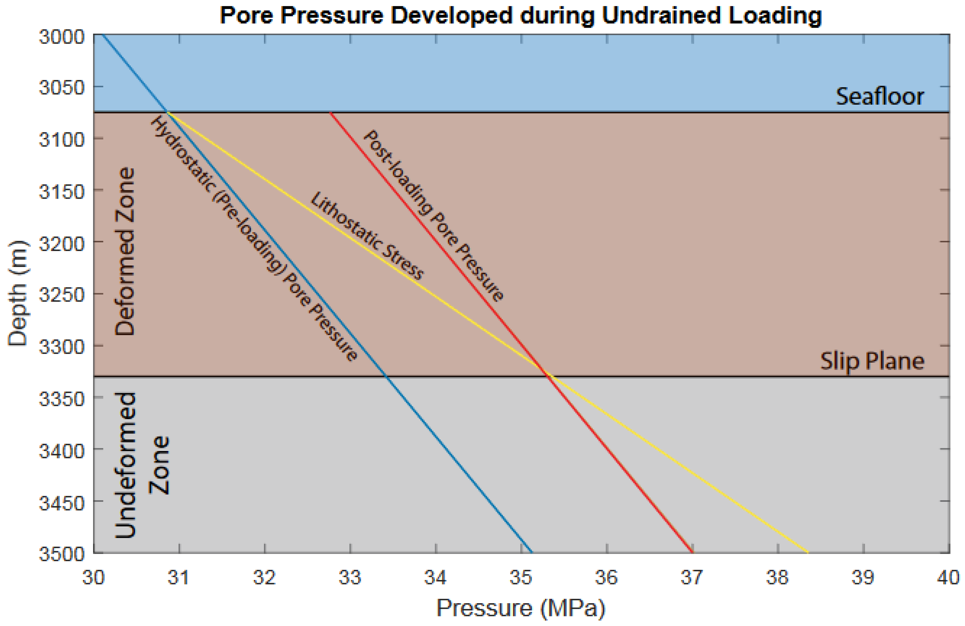
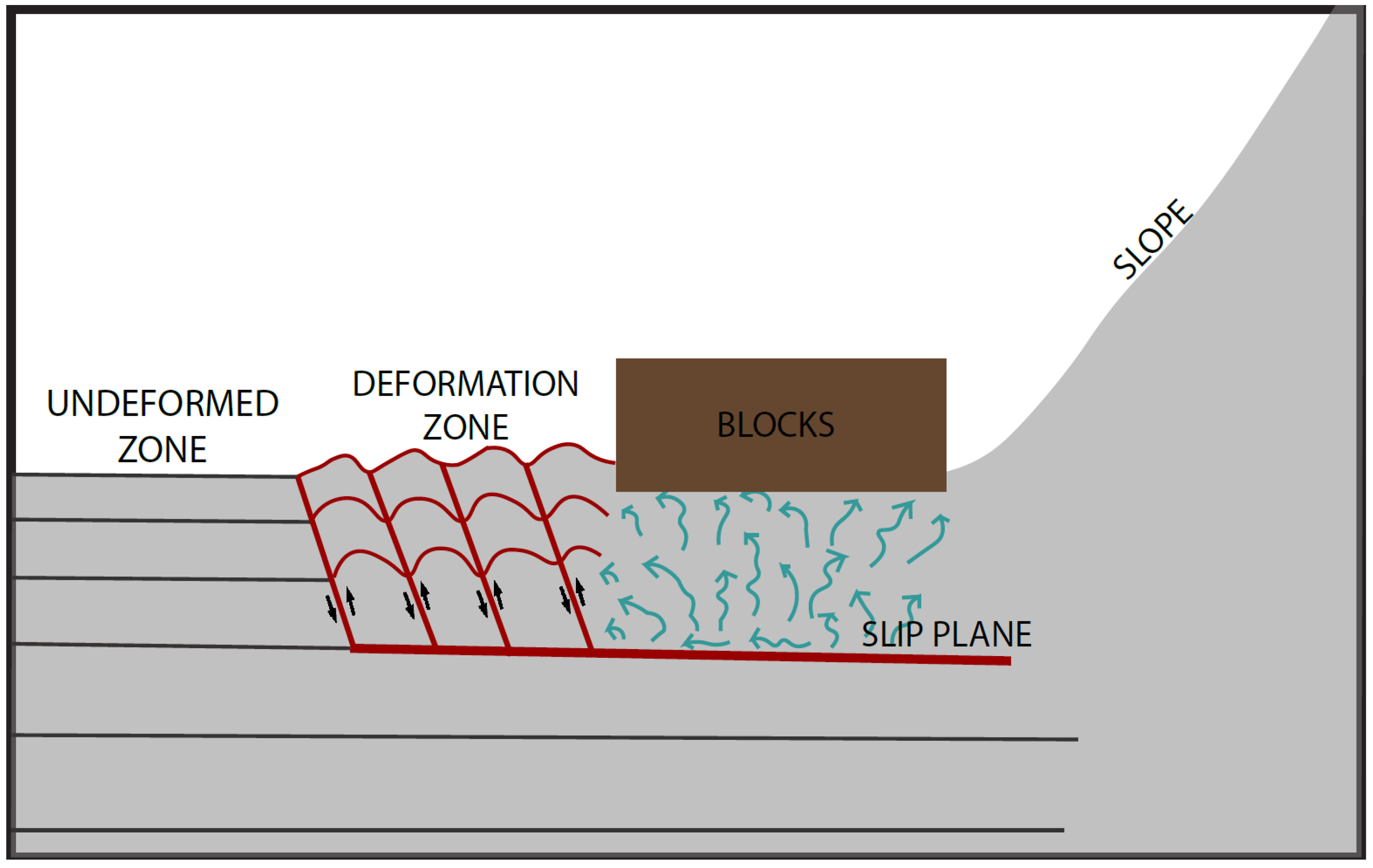
4.1. Impact-Induced Deformation

The deformation zone observed immediately seaward of the 44-North landslide blocks looks very similar to the fold-and-thrust belt structures observed in Lake Lucerne, Switzerland that were the result of gravity spreading induced by the loading of sediment from a submarine landslide, but on a much smaller scale [26]. Some similar seismic facies interpreted as in situ sediment deformation induced by a submarine landslide has been observed in Lesser Antilles [27]. It was concluded to be the cause of the slow increase in the pore pressure over time, causing more slip and deformation to occur post-event [27]. Similar compressional structures were also observed in the toe region of other frontally confined landslides, which are landslides where the run-out is restricted [28]. The deformation observed adjacent to the 44-North landslide, however, is not within the toe of the deposit. Instead, it is located within the in-situ abyssal plane sediment. This deformation zone is similar in appearance to the frontally confined landslides because the deformation occurs along a basal shear surface, or slide plane. However, we interpret that the slide plane in this case can be explained by undrained loading and an overpressure increase immediately after the deposition (Figure 6 and Figure 7). Once the sufficient overpressure is generated, deformation of the substrate seaward of the landslide blocks occurs through induced folding and faulting seen in the seismic data. The pressure-driven deformation is similar to those observed in the Lesser Antilles [27], which has been interpreted to be a long-term process. However, in the case of the 44-North Slide, we suggest that the deformation here occurred nearly instantaneously as evidenced by the undeformed post-event sedimentary drape (Figure 5).

4.2. Influence of Seismic Strengthening

The vane-shear strength data collected on ODP Leg 146 at Site 892 (Figure 2) shows that the sediments that make up the slopes in this part of the margin are relatively stronger than passive margins and in line with other active margins in the world [20,24]. Numerous studies support this seismic strengthening hypothesis, where active margins seem to have enhanced shear strength possibly due to the dewatering and densification of their sediments from repeated seismic events [16,17,24,29]. Even though a major earthquake has not occurred on this margin in about 300 years, episodic low-frequency tremors are a very common occurrence [30] and may play a role in progressively strengthening the sediments. Stronger sediments are more likely to produce a cohesive blocky slide as opposed to a disintegrative slide [6,7,8,9], therefore, the blocky nature of the landslide deposit may be related to seismic strengthening.

4.3. Role of Gas Hydrates

The Cascadia margin hosts many known locations of gas hydrate and methane seeps [31,32,33]. Gas seeps were observed in the multibeam water column viewer during the RR1718 cruise about 190-km north of seismic line 15 on the northern end of Kulm Ridge. The bottom-simulating reflector (BSR) observed in seismic line 15 can be interpreted as the presence of gas hydrate directly beneath the source area (Figure 4). BSR’s mark the base of the gas hydrate stability zone, which is a boundary between gas-hydrate bearing sediment above and free-gas bearing sediment below. BSR’s have been interpreted as weakened zones, where the dissociation of gas hydrate increases the pore-pressure and therefore decreases the sediment strength [34]. Previous work done by Lopez et al. (2010) on a submarine landslide in the northern part of the Cascadia margin suggests that gas hydrates played a significant role in the pre-conditioning of slope failure, so it is not impossible for the same mechanisms to have occurred here on the southern margin [34]. Even if gas hydrate did not influence the original failure, gas hydrates could have influenced the blocky nature of the slide. Gas hydrates have been shown to increase sediment cohesion [35], therefore, the presence of gas hydrate within the failed sediments could have provided an additional component of cohesion that allowed the blocks to retain their shape during transport.

4.4. Tsunami Hazard Implications

Landslide-generated tsunamis are a threat to communities and infrastructures along the coasts. One of the most well-studied submarine landslides, the Storegga Slide, produced a very large tsunami that hit Norway, Scotland, the Faeroe Islands, and Shetland Islands [36]. This landslide geomorphology was very different from the 44-North Slide because the Storegga Slide disintegrated upon failure [10,37,38,39]. The Traenadjupet Slide, northeast from the Storegga Slide, has a similar blocky geomorphology as the 44-North Slide. However, the Traenadjupet Slide did not produce a tsunami [40] despite its cohesive blocky style because it was slow moving [41]. This implies that a blocky landslide does not always produce a tsunami. A high initial acceleration [10,11,12] and maximum velocity [13,14] are still required. A fast-moving blocky landslide would be required to produce a tsunami. The blocky nature of the 44-North slide deposits and the inferred high mobility suggests that this landslide could have been tsunamigenic. We have no direct evidence that the 44-N slide created a tsunami, however, our observations support the possibility. Previous models have also suggested that based on the geomorphology of the slide, it could have created a tsunami up to 42.3 m in height [8]. The southern Oregon margin may produce a tsunamigenic high-mobility blocky slope failure in the event of a large earthquake, contributing to the hazard potential of the margin.

5. Conclusions

New high resolution two-dimensional reflection seismic data revealed compressional deformation features in abyssal plain sediments adjacent to the large blocks of the 44-North submarine landslide offshore Oregon. These deformational features were interpreted to be induced by the impact forces of the blocks along a distinct slip plane created by the immediate increase in pore pressure. Based on the undrained loading calculations and the undeformed post-event sedimentary drape, we can be fairly certain that the deformation occurred geologically instantaneously. The strain accommodated in this deformation zone also suggested a high-mobility style failure. The shape and size of the blocks, as well as the vane shear strength data, suggests this portion of the margin consisted of relatively strong sediments. The sediments would require additional preconditioning factors, such as gas hydrate dissociation, as evidence of a bottom simulation reflector, and a large earthquake event to trigger catastrophic failure. This type of failure has the potential to be tsunamigenic. These observations suggest that offshore Oregon may be more likely to produce tsunamigenic landslides contributing to the overall hazard potential of the margin.

Author Contributions

Conceptualization, B.L., D.S., and A.L.; methodology, B.L., D.S., B.P., K.D., and A.L.; software, all authors.; validation, all authors; formal analysis, B.L.; writing—original draft preparation, B.L.; writing—review and editing, B.L., D.S.; visualization, B.L., and D.S.

Funding

The seismic data used for this study was acquired as part of UNOLS Early Career Seismic Chief Scientist Training Cruise 2017 and funded by NSF-OCE17-14168 and NSF-OCE17-14413.

Acknowledgments

We thank the NSF-funded UNOLS Early Career Seismic Chief Scientist Training Cruise 1718 scientists and crew. We thank Aggeliki Georgiopoulou and Patricia Manley for helpful conversations on earlier versions. We also thank the reviewers for their constructive and helpful comments.

Conflicts of Interest

The authors declare no conflict of interest.

References

  1. Moore, G.W.; Moore, J.G. Large-scale bedforms in boulder gravel produced by giant waves in Hawaii. Geol. Soc. Am. Spéc. Pap. 1988, 229, 101–110. [Google Scholar]
  2. von Huene, R.; Bourgois, J.; Miller, J.; Pautot, G. A large tsunamogenic landslide and debris flow along the Peru Trench. J. Geophys. Res. Solid Earth 1989, 94, 1703–1714. [Google Scholar] [CrossRef]
  3. Harbitz, C.B. Model simulations of tsunamis generated by the Storegga slides. Mar. Geol. 1992, 105, 1–21. [Google Scholar] [CrossRef]
  4. Jiang, L.; LeBlond, P.H. The coupling of a submarine slide and the surface waves which it generates. J. Geophys. Res. Oceans 1992, 97, 12731–12744. [Google Scholar] [CrossRef]
  5. Lee, H.J.; Kayen, R.E.; Gardner, J.V.; Locat, J. Characteristics of several tsunamigenic submarine landslides. In Submarine Mass Movements and Their Consequences; Locat, J., Mienert, J., Boisvert, L., Eds.; Springer: Dordrecht, The Netherland, 2003; pp. 357–366. ISBN 9789401039734. [Google Scholar]
  6. Watts, P.; Borrero, J.C. Probability distributions of landslide tsunamis. In Proceedings of the Tsunami Symposium 2001, Seattle, WA, USA, 7–9 August 2001; Session 6. pp. 697–710. [Google Scholar]
  7. Tappin, D.R.; Watts, P.; McMurtry, G.M.; Lafoy, Y.; Matsumoto, T. Prediction of slump generated tsunamis: The July 17th 1998 Papua New Guinea event. Sci. Tsunami Hazards 2002, 20, 222–238. [Google Scholar]
  8. McAdoo, B.G.; Watts, P. Tsunami hazard from submarine landslides on the Oregon continental slope. Mar. Geol. 2004, 203, 235–245. [Google Scholar] [CrossRef] [Green Version]
  9. Watts, P. Probabilistic predictions of landslide tsunamis off Southern California. Mar. Geol. 2004, 203, 281–301. [Google Scholar] [CrossRef]
  10. Løvholt, F.; Harbitz, C.B.; Haugen, K.B. A parametric study of tsunamis generated by submarine slides in the Ormen Lange/Storegga area off western Norway. In Ormen Lange—An Integrated Study for Safe Field Development in the Storegga Submarine Area; Solheim, A., Bryn, P., Berg, K., Mienert, J., Sejrup, H.P., Eds.; El Sevier: Amsterdam, The Netherland, 2005; pp. 219–231. ISBN 0080446949. [Google Scholar]
  11. Haugen, K.B.; Løvholt, F.; Harbitz, C.B. Fundamental mechanisms for tsunami generation by submarine mass flows in idealised geometries. In Ormen Lange—An Integrated Study for Safe Field Development in the Storegga Submarine Area; Solheim, A., Bryn, P., Berg, K., Mienert, J., Sejrup, H.P., Eds.; El Sevier: Amsterdam, The Netherland, 2005; Volume 22, pp. 209–217. ISBN 0080446949. [Google Scholar]
  12. Grilli, S.T.; Watts, P. Tsunami generation by submarine mass failure. I: Modeling, experimental validation, and sensitivity analyses. J. Waterw. Port Coastal Ocean Eng. 2005, 131, 283–297. [Google Scholar] [CrossRef]
  13. Ward, S.N. Landslide tsunami. J. Geophys. Res. Solid Earth 2001, 106, 11201–11215. [Google Scholar] [CrossRef] [Green Version]
  14. Tinti, S.T.; Bortolucci, E.L.; Chiavettieri, C.I. Tsunami excitation by submarine slides in shallow-water approximation. Pure Appl. Geophys. 2001, 158, 759–797. [Google Scholar] [CrossRef]
  15. Goldfinger, C.; Kulm, L.D.; McNeill, L.C.; Watts, P. Super-scale failure of the southern Oregon Cascadia margin. Pure Appl. Geophys. 2000, 157, 1189–1226. [Google Scholar] [CrossRef]
  16. McAdoo, B.G.; Pratson, L.F.; Orange, D.L. Submarine landslide geomorphology, US continental slope. Mar. Geol. 2000, 169, 103–136. [Google Scholar] [CrossRef]
  17. Nelson, C.H.; Escutia, C.A.; Damuth, J.E.; Twichell, D.C. Interplay of mass-transport and turbidite-system deposits in different active tectonic and passive continental margin settings: External and local controlling factors. Sediment. Geol. 2011, 96, 39–66. [Google Scholar] [CrossRef]
  18. Peters, R.; Jaffe, B.; Peterson, C.; Gelfenbaum, G.; Kelsey, H. An overview of tsunami deposits along the Cascadia margin. In Proceedings of the Tsunami Symposium 2001, Seattle, WA, USA, 7–9 August 2001; pp. 479–490. [Google Scholar]
  19. Shipboard Scientific Party. Site 174. In Deep Sea Drilling Project; DSDP Initial Reports Leg; DSDP: Orange, TX, USA, 2007; Volume 18, pp. 97–167. [Google Scholar]
  20. Shipboard Scientific Party. Site 892. In Proceeding of the Ocean Drilling Program, Initial Reports; Ocean Drilling Program: College Station, TX, USA, 1994; Volume 146, pp. 301–378. [Google Scholar] [CrossRef]
  21. Ryan, W.B.; Carbotte, S.M.; Coplan, J.O.; O’Hara, S.; Melkonian, A.; Arko, R.; Weissel, R.A.; Ferrini, V.; Goodwillie, A.; Nitsche, F.; et al. Global multi-resolution topography synthesis. Geochem. Geophys. Geosystems 2009, 10. [Google Scholar] [CrossRef]
  22. Goldfinger, C.; Nelson, C.H.; Morey, A.; Johnson, J.E.; Gutierrez-Pastor, J.; Eriksson, A.T.; Karabanov, E.; Patton, J.; Gracia, E.; Enkin, R.; et al. Turbidite Event History: Methods and Implications for Holocene Paleoseismicity of the Cascadia Subduction Zone; USGS Professional Paper 1661-F; Geological Survey: Reston, VA, USA, 2012; pp. 184, 64, Figures. Available online: http://pubs.usgs.gov/pp/pp1661f (accessed on 13 November 2018).
  23. Phrampus, B.; Tominaga, M.; Trehu, A.; Lyle, M.W. Multi-channel seismic processed data offshore Oregon, acquired by the R/V Roger Revelle in 2017 (RR1718). Interdisciplinary Earth Data Alliance (IEDA) 2018. [Google Scholar] [CrossRef]
  24. Sawyer, D.E.; DeVore, J.R. Elevated shear strength of sediments on active margins: Evidence for seismic strengthening. Geophys. Res. Lett. 2015, 42, 10–216. [Google Scholar] [CrossRef]
  25. Sawyer, D.E.; Flemings, P.B.; Dugan, B.; Germaine, J.T. Retrogressive failures recorded in mass transport deposits in the Ursa Basin, Northern Gulf of Mexico. J. Geophys. Res. Solid Earth 2009, 114. [Google Scholar] [CrossRef] [Green Version]
  26. Schnellmann, M.; Anselmetti, F.S.; Giardini, D.; McKENZIE, J.A. Mass movement-induced fold-and-thrust belt structures in unconsolidated sediments in Lake Lucerne (Switzerland). Sedimentology 2005, 52, 271–289. [Google Scholar] [CrossRef]
  27. Hornbach, M.J.; Manga, M.; Genecov, M.; Valdez, R.; Miller, P.; Saffer, D.; Adelstein, E.; Lafuerza, S.; Adachi, T.; Breitkreuz, C.; et al. Permeability and pressure measurements in Lesser Antilles submarine slides: Evidence for pressure-driven slow-slip failure. J. Geophys. Res. Solid Earth 2015, 120, 7986–8011. [Google Scholar] [CrossRef] [Green Version]
  28. Frey-Martínez, J.; Cartwright, J.; James, D. Frontally confined versus frontally emergent submarine landslides: A 3D seismic characterisation. Mar. Pet. Geol. 2006, 23, 585–604. [Google Scholar] [CrossRef]
  29. Ten Brink, U.S.; Andrews, B.D.; Miller, N.C. Seismicity and sedimentation rate effects on submarine slope stability. Geology 2016, 44, 563–566. [Google Scholar] [CrossRef]
  30. Rogers, G.; Dragert, H. Episodic tremor and slip on the Cascadia subduction zone: The chatter of silent slip. Science 2003, 300, 1942–1943. [Google Scholar] [CrossRef] [PubMed]
  31. Suess, E.; Carson, B.; Ritger, S.D.; Moore, J.C.; Jones, M.L.; Kulm, L.D.; Cochrane, G.R. Biological communities at vent sites along the subduction zone off Oregon. Bull. Biol. Soc. Wash. 1985, 6, 475–484. [Google Scholar]
  32. Kulm, L.D.; Suess, E.; Moore, J.C.; Carson, B.; Lewis, B.T.; Ritger, S.D.; Kadko, D.C.; Thornburg, T.M.; Embley, R.W.; Rugh, W.D.; et al. Oregon subduction zone: Venting, fauna, and carbonates. Science 1986, 231, 561–566. [Google Scholar] [CrossRef] [PubMed]
  33. Ritger, S.; Carson, B.; Suess, E. Methane-derived authigenic carbonates formed by subduction-induced pore-water expulsion along the Oregon/Washington margin. Geol. Soc. Am. Bull. 1987, 98, 147–156. [Google Scholar] [CrossRef]
  34. López, C.; Spence, G.; Hyndman, R.; Kelley, D. Frontal ridge slope failure at the northern Cascadia margin: Margin-normal fault and gas hydrate control. Geology 2010, 11, 967–970. [Google Scholar] [CrossRef]
  35. Waite, W.F.; Santamarina, J.C.; Cortes, D.D.; Dugan, B.; Espinoza, D.N.; Germaine, J.; Jang, J.; Jung, J.W.; Kneafsey, T.J.; Shin, H.; et al. Physical properties of hydrate-bearing sediments. Rev. Geophys. 2009, 47. [Google Scholar] [CrossRef]
  36. Bondevik, S. Storegga tsunami sand in peat below the Tapes beach ridge at Harøy, western Norway, and its possible relation to an early Stone Age settlement. Boreas 2003, 32, 476–483. [Google Scholar] [CrossRef]
  37. Berg, K.; Solheim, A.; Bryn, P. The Pleistocene to recent geological development of the Ormen Lange area. In Ormen Lange—An Integrated Study for Safe Field Development in the Storegga Submarine Area; El Sevier: Amsterdam, The Netherland, 2005; pp. 45–56. [Google Scholar]
  38. Bryn, P.; Berg, K.; Forsberg, C.F.; Solheim, A.; Kvalstad, T.J. Explaining the Storegga slide. Mar. Pet. Geol. 2005, 22, 11–19. [Google Scholar] [CrossRef]
  39. Kvalstad, T.J.; Andresen, L.; Forsberg, C.F.; Berg, K.; Bryn, P.; Wangen, M. The Storegga slide: Evaluation of triggering sources and slide mechanics. In Ormen Lange—An Integrated Study for Safe Field Development in the Storegga Submarine Area; El Sevier: Amsterdam, The Netherland, 2005; pp. 245–256. [Google Scholar]
  40. Løvholt, F.; Bondevik, S.; Laberg, J.S.; Kim, J.; Boylan, N. Some giant submarine landslides do not produce large tsunamis. Geophys. Res. Lett. 2017, 44, 8463–8472. [Google Scholar] [CrossRef] [Green Version]
  41. Laberg, J.S.; Vorren, T.O. The Trænadjupet Slide, offshore Norway—Morphology, evacuation and triggering mechanisms. Mar. Geol. 2000, 171, 95–114. [Google Scholar] [CrossRef]
Figure 1. (A) Map of the Cascadia subduction zone with seismic line 15 from RR1718. The yellow box indicates the area shown in Figure 1B. Red stars indicate core locations [19,20]. Bathymetry created using the Global Multi-Resolution Topography (GMRT) database from http://www.geomapapp.org [21]. (B) Map view of the area containing seismic line 15. The orange box indicates the portion of seismic line 15 in Figure 3, as well as the zoomed in map of the 44-N Slide in Figures 1C and 3C. Red stars indicate core locations [19,20,22]. PC indicates piston cores and the cruise leg and site numbers indicate the other cores. The 44-N Slide is in close proximity to one of the scarps from three previously studied megaslides, the Heceta Slide [3]. Bathymetry created using the Global Multi-Resolution Topography (GMRT) database from http://www.geomapapp.org [21]. (C) Map view of the area containing the eastern half of seismic line 15, showing the prominent head scarp from the 44-North slide. Bathymetry created using the Global Multi-Resolution Topography (GMRT) database from http://www.geomapapp.org [21].
Geosciences 09 00010 g001
Figure 2. Plot of the vane peak undrained shear strength for the upper 100 meters below seafloor for passive margins (blue) and active margins (red) with ODP Leg 146 Site 892 overlain (black). This plot suggests the pre-failure sediment of the 44 North Slide could have had a similar profile of relatively strong shear strength. Figure modified from Sawyer and DeVore, 2015 [24].
Geosciences 09 00010 g002
Figure 3. (A) Eastern half of seismic line 15 from RR1718 uninterpreted. (B) Eastern half of seismic line 15 interpreted. Green lines represent reverse faults and gray vertical dotted lines indicate fluid pathways. Horizontal dashed lines represent inferred layers and boundaries. The base of the landslide blocks is also an inferred boundary. (C) Map view of area containing the eastern half of seismic line 15. Bathymetry created using the Global Multi-Resolution Topography (GMRT) database from http://www.geomapapp.org [21].
Geosciences 09 00010 g003
Figure 4. Portion of seismic line 15 that contains the source area for the 44-N Slide with the main head scarp observed in the bathymetry data indicated. The 44-N slide probably occurred over this zone as an evacuation zone and has other smaller head scarps. The bottom-simulating reflector (BSR) observed can be interpreted as the presence of gas hydrate. A BSR can be seen beneath the source area of the 44-N slide.
Geosciences 09 00010 g004
Figure 5. Portion of seismic line 15 that contains the frontal deformation zone of the 44-N Slide (A) Uninterpreted. (B) Interpreted. Green lines indicate thrust faults and vertical dotted lines indicate fluid pathways. Onlapping seismic reflectors are interpreted as post-event sedimentary drape, which appears to be undeformed suggesting the deformation occurred instantly.
Geosciences 09 00010 g005
Figure 6. Theoretical pore pressure immediately after the deposition of the large 44-N landslide blocks on the seafloor. Post-loading pore pressure (yellow) exceeds lithostatic stress (orange) to a depth of the slip plane identified by seismic (Figure 5). This pore pressure profile assumes initial hydrostatic pore pressure (blue) and undrained loading of the weight of the blocks.
Geosciences 09 00010 g006
Figure 7. Conceptual model showing undrained pore pressure development immediately after deposition of landslide blocks.
Geosciences 09 00010 g007

