Abstract
Samples of mortars were collected from lime and hydraulic mortars affected by environmental degradation. A total of 63 samples were obtained from Hellenistic, Late Roman and Byzantine historic constructions located at Kavala, Drama and Makrygialos in North Greece. Samples were collected in sections from the surface up to 6 cm deep using a drill-core material. The first sample was collected from the external layer, while the internal samples were collected each 1cm beeper from the previous, in order to monitor the moisture ingress. Isotopic data will make it possible to create an ideal Hellenistic and Byzantine mortar layer and to provide weathering gradients. The isotopic values comprise a range of δ13C and δ18O values from −17.1‰ to 1.2‰ and −25.9‰ to −2‰, respectively. The weathering process of Hellenistic and Byzantine are expressed, by the regression lines δ18Ocalcite matrix = 0.6 × δ13Ccalcite matrix − 1.9 and δ18Ocalcite matrix = 0.6 × δ13Ccalcite matrix − 2.0 for hydraulic and Lime mortars respectively. Pronounced isotopic shift to heavy or light δ13C and δ18O in the carbonate matrix was attributed to the primary source of CO2 (atmospheric versus biogenic) and H2O (evaporation of local primary water), in residual limestone and in secondary processes such as recrystallization of calcite with pore water and salts attack. Exogenic processes related to biological growth are responsible for further alterations of δ18O and δ13C in lime mortars. This study indicated that stable isotope analysis is an excellent tool to fingerprint the origin of carbonate, the environmental setting conditions of mortar, origin of CO2 and water during calcite formation and to determine the weathering depth and the potential secondary degradation mechanisms.
1. Introduction
It is very important to respond to major new challenges regarding the conservation of cultural heritage, by predicting deterioration features and evaluating the nature of damages monuments. Its preservation demonstrates recognition of the necessity of the past while on a different level ensures a mean for the validation of human-memories and confirms human history. The material nature of monuments is what makes it so important, allowing a direct interaction with human senses, yet it also entails that it is a constant state of chemical transformation, making its preservation an everlasting task of continuously growing importance. Hydraulic and lime mortars constitute main structural components in architectural constructions. Environmental degradation of historic mortars are a main threat for the preservation of historic monuments [1,2,3,4,5,6]. The main agents of decay (such as acid attack, leaching action, salts attack, damage due to frost and fire, insufficient mixing and choice of constituents) can cause extensive cracks and total disintegration of historic constructions [7,8,9,10]. There are two main categories of limes, hydraulic and non-hydraulic. Lime is formed by burning a source of calcium carbonate such as limestone to evolve carbon dioxide and form calcium oxide (1) [(CaO, quicklime)]. The calcium oxide is then slaked with water under heating to produce calcium hydroxide (slaked lime, Ca(OH)2) (2). This mass will be then mixed with aggregate materials such as sand, gravel, crushed stone or iron blast-furnace slag and various organic and inorganic additives such as pozzolanic materials or mud, forming calcium carbonate (3). The mortar hardens with the absorption of carbon dioxide from the atmosphere gaining strength. The formation of calcium carbonate mortars is described in the following reactions:
CaCO3→CaO + CO2
CaO + 2H2O→Ca(OH)2 + H2O
Ca(OH)2 + CO2→CaCO3 + H2O
The reactions within the formation of hydraulic compounds are described below:
CaO + Al2O3→CaOAl2O3
2CaO + SiO2→2CaOSiO2
The sources of mortar decay could be physical, related to physical variations of water inside masonry (evaporation, capillary flow, ice formation, etc.) or chemical (formation of expansive products such as ettringite and thaumasite).
Also, lime-based mortars can be easily attacked by sulphur compounds. Sulfation occurs when a layer of gypsum is formed in the surface of calcite that is more soluble than calcite (6).
CaCO3(s) + SO2(g) + 1/2O2(g) + 2H2O(g)→CaSO42H2O(s) + CO2(g)
Therefore, in the presence of water (rain) this gypsum layer is dissolved, causing dissolution of the external calcite layer. Furthermore, concrete deterioration can be related to internal sulfate attack. Aggregates containing sulfide minerals (pyrite) can become an internal source of sulfate ions. These ions can promote the development of chemical reactions with the cement paste composition, which may result in the formation of expansive and deleterious products that are typical of sulfate attack known as ettringite, gypsum and thaumasite [11,12].
In order to determine the above degradation mechanisms and propose suitable conservation strategies, it is essential to examine the calcium carbonate origin and to identify the possible causes that changed the initial composition. Stable isotopic data provides information of the primary sources of raw material and offers considerable potential in the investigation of lime mortar and lime plaster (composed of sand, water, and lime and often contained horse hair for reinforcement and pozzolan additives). In particular, stable isotope fingerprinting is a concept that has been successfully developed and applied in earth sciences for several decades [13,14]. The elements C and O have a characteristic isotope ratio that varies slightly but significantly when transformations like phase changes or chemical reactions occur. Those slight variations can be measured and allow for valuable conclusions to be drawn on the origin and the history of these elements. Previous studies on historical mortars implemented mineralogical and chemical analysis, evaluation of the aggregate to matrix ratio and provenance of raw materials [15,16,17,18]. However, studies focused on stable isotope analysis of lime mortars are rare [19,20]. Furthermore, little is known about the isotopic change of the initial C and O in carbonate matrix that was caused by alteration of the primary source of CO2 and H2O in mortar over time. Human influence and biological growth are major exogenic processes which alter O and C in lime mortar. In particular oxygen isotope is common between CO2 and H2O and has the potential to elucidate the history of primary source of H2O or alteration processes with water of meteoric origin, while carbon isotope composition can identify the origin of CO2. Finally, the main objective of this study is to examine the sources of mortar decay in four Hellenistic, Roman, Late Roman and Byzantine masonries. The determination of the exact origin of the materials is the key to reach the above objective and this can be achieved using stable isotopes. Furthermore, stable isotope analysis will allow examining what has changed relatively to environmental conditions and secondary processes from ancient time until today, to distinguish the nature of the structural materials used (mortar) and to disambiguate the causes that incurred the degradation phenomena.
2. Methods and Materials
2.1. Methods
Mortar lumps were analyzed using Scanning Electron Microscopy (SEM) with Energy Dispersive X-ray (EDX) analysis since this technique is considered a powerful tool to characterize the microstructure of the materials [21,22].
Major and minor elements for polished mortar samples were analyzed using a FEI/Quanta Inspect D8334 SEM, FEI company, Hillsboro, OR, USA, fitted with a low vacuum chamber and an energy dispersive X-ray analyzer at NCSR “Demokritos”, Athens, Greece. The operating conditions were a 25 KV accelerating potential and a 107 μA emission current, giving a count rate of 400 cps on metallic cobalt, the working distance was normally 10 mm. The detector was calibrated with a range of pure elements, synthetic oxides and well characterized minerals. The mortar samples were vacuum-dried, polished in resin blocks, mounted onto metal stubs and coated with a thin film of gold and examined with the SEM.
The elements present in the mortar samples were determined using X-ray measurements of each particle. A backscattered electron image was obtained in every sample and qualitative analysis of 10–20 individual particles was performed. For bulk analysis of mortars, the SEM beam was rastered on each sample at 100× over a 4 × 3 mm sized area. Accuracy and precision in bulk analysis for mortar samples were expected to be somewhat reduced because mortars are heterogeneous materials, however for comparative purposes the results were normalized to 100% and are considered to give an approximation of the major oxides. The imaging was performed using four-quadrant Backscattered Electron Imaging (BSE). The backscattered images enabled the determination of the structural components in mortars, since heavy elements such as iron and lead appear brighter than light elements such as carbon or oxygen. As a result, backscattered electron images demonstrate the make-up of mortars, because sharp changes in grey levels represent different compounds.
Mineralogical analysis was achieved using optical microscopy [22,23]. Optical microscopy was performed using a polarizing microscope at the Department of Mineralogy, Petrology and Economic Geology at Aristotle University of Thessaloniki. Thin sections were prepared by drying the samples (lumps) using acetone in vacuum. The samples were vacuum impregnated with epoxy resin, cut with a slow-speed diamond saw to minimize damage and then mounted on glass slides and ground to 30 mm thickness. Observations were made under crossed polars (XPL) using a Leitz Laborlux 11 POL S, (Leica Microsystems’ Microscopy and Scientific Instruments, Wetzlar, Germany). The aggregate clasts, and the fine-grained calcite, may be identified using common geological techniques [24,25]. The terminology developed for the description of archaeological ceramics was applied to some extend in mortar cross section investigations [26,27].
The isotopic analyses took place at Stable Isotope Unit of Institute of Nanosciences and Nanotechnology (NCSR “Demokritos”) on a Thermo Delta V Plus IRMS equipped with GasBench II device. Mortar samples were separated using scalpels in two or three sections reflecting the changes in isotopic composition from interior to exterior. Small quantities of clean (leached with acetic acid) carbonate material were separated and after grinding to a fine powder were diluted in ortho-phosphoric acid and the CO2 produced was measured in the isotope ratio mass spectrometer. The isotopic results are reported in the usual delta terminology versus VPDB isotopic standard, delta being defined as follows: δ = [(Rsample − Rstandard)/Rstandard] × 1000 where R is the ratio between the heavy and the light isotope, in this case 18O/16O or 13C/12C. The reported values are the mean of two or more consistent measurements of each sample. The standard deviation of the materials measurements is very good, ranging on average between ±0.1‰ and ±0.2‰ [28,29,30].
2.2. Materials
A total of 63 samples were obtained from four Hellenistic, Late Roman and Byzantine historic constructions located at Kavala, Drama and Makrygialos in North Greece (Figure 1). The location of the studied sites is considered maritime therefore all the architectural constructions and all mortar samples are seriously affected by salt crystallization [31,32]. Also, extensive fragmentation is observed in fortification walls in Drama, in Marmarion tower in Kavala and in funerary monuments in Makrygialos. Different types of crust are also observed in the surface of the mortars. Dark soiling patterns are observed on the mortars surface. Black crusts are likely to be derived from secondary recrystallization of calcitic binders while green crusts are associated with biodegradation and biological growth. The samples were collected in sections by pressing a drill-core material 6 cm towards the surface. The first sample was collected from the surface, while the internal samples were collected each 1cm beeper from the previous. The samples collected from the exterior layers are exposed to environmental degradation while the samples collected from interior layers do not possess any evidence of degradation.
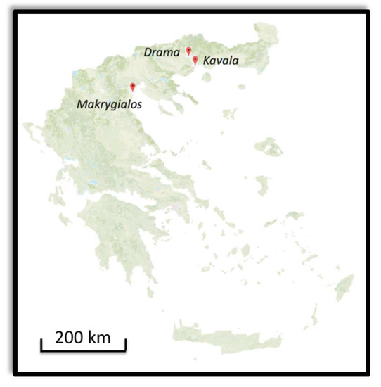
Figure 1.
Map of sampling locations. Makrygialos (40°25′ N 22°36′ E), Drama (41°9′ N 24°8′ E), Kavala (40°56′ N 24°24′ E).
2.2.1. Anaktoroupoli and Land Walls in Kavala
Samples (AN1a-1 to Anp-1) were obtained from Anaktoroupoli which is an area located in the region of Nea Peramos in Kavala, Greece. In specific, Anaktoroupoli is the remaining of a Byzantine town located in the west coast of Kavala. It is dated at 14th century AD based on the characteristics of the masonry and the features observed in the coins excavated in the region [33]. The samples collected from this site were joints. The joints of the brickwork structure are 2 ± 4 cm thick, and probably have a bearing function [34]. A few samples were also collected from land walls in Kavala (KA1b, KA5 and KA6), but these were not included in stable isotope analysis, because of analytical errors (the samples KA1b, KA5, KA6 were entirely covered with salt and the SEM detector could not detect the other constituents). Land walls in Kavala were constructed in four different historical periods; however samples selected were characterized as late Byzantine (9th to 10th century).
2.2.2. Marmarion Tower in Kavala
Samples (MA1-3 to MA5-2) were collected from Marmarion tower in Kavala, Greece. The Marmarion tower was built in 1367 by Priests Alexios and Ioannis for the Ancient Monastery of Pantokratoras. The tower is constructed using secondary ancient material, mainly sandstones, marlstones, fired bricks and good quality lime mortar. The ancient material is composed of large marlstones from architectural parts such as inscribed columns [34].
2.2.3. Fortification Walls in Drama
Samples (DRa-1 to DR2g-1) were obtained from joints located at fortification walls that surround the historical center of Drama, one of the most important monuments of the region [34]. Two main parts of the walls have survived: the northern parts have been almost entirely preserved, apart from the north-eastern corner and all of the west part. The walls were founded in Late Roman times (3th–6th century AD) and later building phases are ascribed to the Frankish period. Modern building materials were identified, added possibly within restoration treatments. This study will examine samples from the Later Roman building phase.
2.2.4. Funerary Monuments in Makrygialos
Mortar samples (MK1-1 to MK10-2) were obtained from 4th century BC Hellenistic tombs in the area of Pydna in North Greece. Ancient Pydna lies in the North of Pieria, two kilometers away from South Makrygialos. The monuments were discovered in rescue excavations under the supervision of KZ’ Ephoreia of Classical and Prehistoric Antiquities [35].
3. Results
3.1. Micromorphological and Elemental Analysis
3.1.1. Anaktoroupoli-Land Walls Kavala
Backscattered electron photomicrographs of sample AN1b, representative of the group of samples obtained from Anaktoroupoli, Nea Peramos, illustrates the morphology of a Byzantine mortar. The photomicrograph (Figure 2) depicts large irregularly shaped grains acting as aggregates, while the matrix is composed from homogeneous smaller grains. The sample is composed of 50.7% quartz and 31.7% CaO according to bulk analysis of oxides in the SEM and the ternary plot with EDX values (Table 1). Petrographic analysis elucidated that the matrix is composed of microcrystalline calcite (Figure 3). Thin section demonstrates that this is a coarse mortar, the size of mineral components rises up to 6 mm. The mineralogical composition of the aggregates in this sample includes quartz, calcite, plagioclase, potassium feldspar, microcline, muscovite and traces of sericite and kaolinite. Thin section photomicrograph indicates that quartz is the most abundant mineral, in line with SEM analysis; quartz grains reach up to 3 mm. Quartz is usually coarse and shows a strong recrystallization layer on the boundaries of quartz grains. Most of the mineral components demonstrate rounded cavities surrounded by a thin layer of calcite. Backscattered electron photomicrograph reveals fibrous crystals of sericite (indicated with black arrow) with hexagonal structure and needle morphology (10 mm in length) are present as parts of the aggregate fraction. Calcitic matrix shows intensive fragmentation and cracks attributable to the degradation of mortar over time. Extensive deposition of salts is observed in sample K5, obtained from land walls in Kavala. The surface of the mortar is entirely covered with salts. Point analysis detected the elements Na and Cl on the entire surface of the sample.
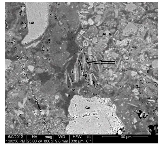
Figure 2.
SEM/Backscattered Electron Imaging (BSE) (×253) photomicrograph of sample AN1b from land walls in Kavala. The black arrow indicates fibrous crystals of sericite.

Table 1.
Data in weight per cent oxide normalized to 100%.
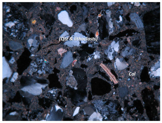
Figure 3.
Crossed polar (XPL), magnification 5 × 5 mm, photograph length 2 mm. Byzantine mortar AN1b. The binder is composed microcrystalline calcite while the aggregates are composed of quartz grains and lithoclasts in sedimentary petrology.
3.1.2. Fortification Walls in Drama
SEM-EDX microstructural observations and thin section analysis revealed the morphology of DR2c (Figure 4) representative sample from fortification walls in Drama. Bulk analysis of oxides (Table 1) with SEM demonstrates that mortar samples from Drama are composed of 13.0% CaO and 57.6% of SiO2. Point analysis of elements in each sample also revealed that Si occurred as the most abundant element in all SEM-EDX measurements. Minor elements detected were Al, Mg, Cl and Fe. Parallel to elemental analysis using SEM, thin section analysis in the polarized optical microscope demonstrates that the aggregates in the mortar samples from Drama are composed of quartz, calcite, plagioclase, potassium feldspar, biotite, muscovite with traces of granite, actinolite and tourmaline. The matrix is composed of fine grained calcite. When viewed in XPL sample DR2c has an overall brownish color, since this sample contains minerals and fragments of crushed bricks with maximum size 1 cm. Looking at photomicrograph (Figure 5), quartz demonstrates a coarse structure, at the same time appears a strong recrystallization matrix in saturation boundaries. XPL observations reveal the presence of muscovite together with quartz. The aggregate is formed from a pozzolanic additive of crushed and powdered ceramics plus a geological material such as volcanic rock with particles of variable composition. Muscovite is dispersed through calcitic binding material in the form of leafs with size up to 1mm. The presence of plagioclase is rare. Ceramic components are composed of muscovite, quartz and calcite. Elemental analysis also detected traces of chlorine in all samples, providing evidence for extensive deposition of salts. All samples demonstrate porous morphology that enhances the transportation of salts in the mortar structures using moisture. The black holes in the mortar structure are attributed to shrinkage within the polishing process and they do not represent evidence of porosity.
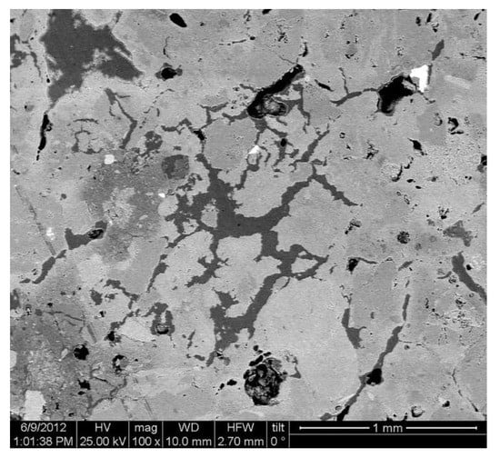
Figure 4.
SEM/BSE (×253) photomicrograph of sample DR2c from fortification walls in Drama. Microstructural observations and thin section analysis.
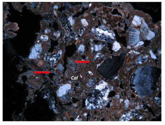
Figure 5.
XPL, magnification 13 × 10 mm, +N, photograph length 1mm. Byzantine mortar, DR2c from fortification walls in Drama. The binding material is composed of calcite, pozzolanic reactions are observed (the arrows indicate the reactions), crushed ceramics and rock fragments compose the aggregates.
3.1.3. Marmarion Tower—Kavala
SEM/BSE and XPL photomicrographs demonstrate the microstructure of sample MA3 representative of samples obtained from Marmarion tower in Kavala (Figure 6 and Figure 7). Bulk analysis of oxides shows that this sample contains 47.73% of CaO and 36.54% of SiO2. Point analysis of individual elements showed that the aggregate is mostly composed of Si-rich particles while the matrix is composed of Ca-rich particles. The mineralogical composition of the matrix is detected using thin section analysis; the binding material is composed of fine-grained calcite. The aggregate can be readily discriminated from the matrix on the basis of its different mean atomic number, as shown in Figure 6. The aggregate is composed of quartz, calcite, plagioclase, potassium feldspar, microcline, biotite, muscovite while traces of chlorite were detected in the sample. XPL observations demonstrate that the length of quartz rises up to 2 mm and it is usually coarse. Quartz grains are surrounded by a strong recrystallization layer in the saturation boundaries. Calcite demonstrates intensive cracks and fragmentation, while signs of recrystallization layers are observed in a few samples. Elemental analysis also detected traces of Cl-rich particles in all samples, providing evidence for deposition of salts. All samples demonstrate porous morphology, which enhances the transportation of salts in the mortar structures using moisture.
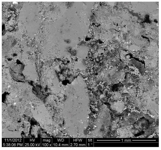
Figure 6.
SEM/BSE (×300) photomicrograph of sample MA3 obtained from Marmarion tower.
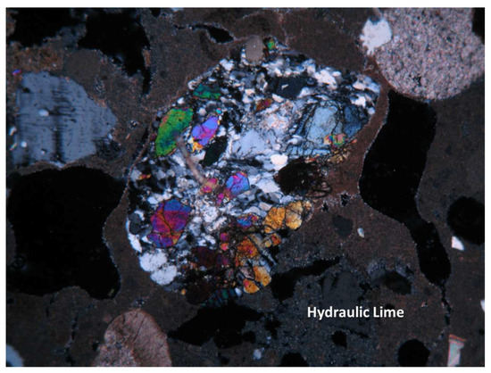
Figure 7.
XPL, magnification 6 ×5 mm, +N, photograph length 2 mm. Sample MA3 obtained from Marmarion tower, it is a typical lime pozzolan mortar.
3.1.4. Makrygialos
Backscattered electron and XPL photomicrographs of sample MK4 (Figure 8 and Figure 9), illustrate the morphology of typical mortar sample from Makrygialos, Greece. The photomicrographs (Figure 8a,b) depict large irregularly shaped lithoclast composed mainly of quartz (up to 58.7%) and feldspar, as shown by bulk analysis of oxides in the SEM (Figure 10). Petrographic observation elucidates that this is a textured mortar with mineral components sized from 100 μm to 4 mm. The matrix is composed from fine calcitic particles including also quartz grains, bulk analysis of oxides detected 95.6% percentage of CaO (Table 1, Figure 10). The matrix is composed of micritic calcite that is interrupted by angular aggregates and pores. XPL observation demonstrated that the mineralogical composition of the aggregate is: microcrystalline calcite with quartz, plagioclase, orthoclase, microcline, biotite, muscovite and traces of chlorite, zircon, titanite. Volcanic grains are also observed. The size of quartz grains is approximately 2 mm. The black holes in the pictures (Figure 8a,b) are pores in the mortar structure. In this sample, it is possible to have two types of pores. The elongate cracks are attributed to shrinkage and the rounded pores are derived from bubbles during setting. In places where heating was more intense, the half-burnt limestone fragments show an edge along the area of a crack (pore) [(Figure 8b, indicated with yellow arrow)]. It represents deposition of calcite on the edge of the crack due to the movement of solutions during burial. Thin section analysis also reveals the presence of unreacted lime and rare particles of partially or unburned limestone. The black hole in Figure 8b is lined with a very light grey line composed of calcite. This pore lining requires a source of dissolved carbonate. The dissolved carbonate could be attributed to the dissolution of calcite matrix or dissolution of the calcitic particles in the aggregate. In sample MK4 the matrix is mostly composed of calcite, therefore the pore lining is attributed to the dissolution of calcite matrix. Fine calcite particles (indicated with black arrow) in the matrix is attributed to limestone relicts that are derived from insufficient burning.
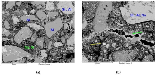
Figure 8.
(a,b) SEM/BSE (×100) photomicrographs of sample MK4 obtained from Makrygialos. The potential minerals are quartz (up to 58.7%) and feldspar. The matrix is composed mainly from calcite and quartz. The arrows in (b) indicate half-burnt limestone fragments.
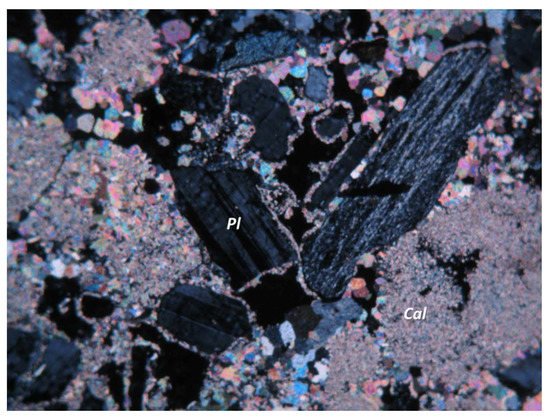
Figure 9.
XPL, magnification 1 × 5 mm, +N, photograph length 2 mm. Hellenistic mortar sample MK4 obtained from Makrygialos, Greece. Microcrystalline calcite and plagioclase as aggregates.
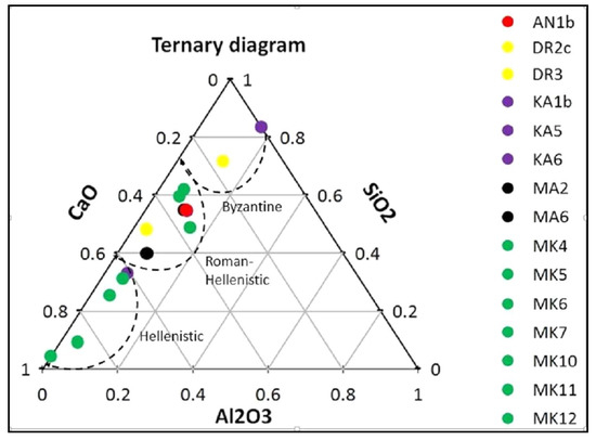
Figure 10.
CaO-Al2O3-SiO2% ternary plot of Energy Dispersive X-ray (EDX) analyses of data collected from mortar samples: Hellenistic mortars (ΜΚ4-12), Roman mortars (A1b, DR2c, DR3), Byzantine mortars (ΚA1β, Κ5, Κ3A).
3.2. Stable Isotope Analysis
The δ13C and δ18O of calcite matrix of the Byzantine, Late Roman and Hellenistic mortar indicate a wide range of isotopic values ranging between −17.1‰ to 1.2‰ and −25.9‰ to −2.0‰, respectively (Table 2). Additional samples of local marine limestone of Cretaceous age were obtained. These samples are located in the vicinity of the historical buildings and they were used as ancient raw materials for burning. The limestones comprise a range of δ13C values between 0 and 3‰ and of δ18O between −5‰ and −2‰ [19] indicating that the isotopic compositions of the calcite matrix from historical mortar are in general lighter, compared to those of local limestone. These light isotopic values are attributed to the absorption of carbon dioxide from the atmosphere within the setting of lime mortar (13CCO2 = −6).
Table 2.
List of analyzed samples and their isotopic value.
22 drill-core samples (presented in Table 2 and they represent samples with increasing isotopic values from the exterior to the interior layer) were examined in order to create an ideal Hellenistic and Byzantine mortar layer and to provide weathering gradients using isotopic analysis. The isotopic values of lime-pozzolan and lime mortar are shown in (Figure 11). In Table 3 we present the results of cross-section analysis. The isotopic values of these samples comprise a range of δ13C and δ18O values from −13.6 ‰ to 3.6‰ and from −12.6 ‰ to 0.4‰, respectively. Most of these samples indicate that calcite matrix is isotopically heavier inside the mortar layer, compared to those of the exterior layer, probably due to the reaction of atmospheric CO2 with the lime mortar. A positive correlation of δ13C vs. δ18O of calcite is observed that is expressed by the regression lines δ18Ocalcite matrix = 0.61 × δ13Ccalcite matrix − 1.8 (lime mortars line in Figure 11) and δ18Ocalcite matrix = 0.63 × δ13Ccalcite matrix − 2 (hydraulic mortars line in Figure 11) for Hellenistic and Byzantine mortar, respectively. The slope of these equations is close to that is expressed by the experimentally obtained equation from Kosednar Legenstein et al., [20].
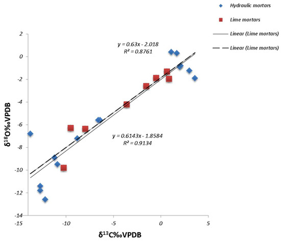
Figure 11.
δ13C vs. δ18O for all the samples. Regression lines for hydraulic and lime mortars.
Table 3.
List of cross-section analysis.
These lines comprise ideal mortar layers representing continues calcite formation with continues enrichment of 18O versus 16O and 13C vs. 12C in the CO2 gas phase and the precipitated calcite. It appears that the quantity percentage and the quality of the charge do not influence significantly the 13C of carbonate formed. The other data from mortars lie close or below this line indicating different setting environments and secondary effects. Also, in most Hellenistic samples it is noted that at interior levels the calcite is depleted in 13C, compared to the middle layer. This depletion in 13C can be explained by the heterogeneity of lime mortar, because this material is not chemically homogenous [36]. Also, higher δ18O values are present in the near surface layer. The enrichment in 18O in the near- surface layers is due to the contribution of water even if only 1/3 of the oxygen in the solid carbonate came from the water. Consequently, despite the contribution of water is minor, it causes this “surface effect” or oxygen enrichment because of important evaporation of water especially near the surface of the mortar (see Section 4.2 for further analysis).
4. Discussion
4.1. Technological Variations and Degradation Mechanisms
In comparing the technology of Hellenistic mortars from Makrygialos Greece with the later mortars (Roman and Byzantine) the first aspect to emphasize is that the lime-based mortars used in funerary monuments in Makrygialos were replaced with advanced lime-pozzolan mortars in Roman and Byzantine constructions. The content of lime in Hellenistic mortars approaches the 96%, whereas the content of lime in Roman and Byzantine mortars is between 30% and 90%. Furthermore, the aggregates in Hellenistic mortars are composed of quartz, plagioclase and potassium feldspar, whereas the aggregates of later mortars are composed of quartz, plagioclase, potassium feldspar, microcline, crushed ceramic and lithoclasts. The ternary plot (Figure 10) depicts the differentiations in mortar composition, since mortar samples obtained from Makrygialos are concentrated in the corner that expresses the maximum content of (CaO), moreover Roman and Byzantine mortars are concentrated in the corner with maximum content of (SiO2). Roman and Byzantine mortars demonstrate coherence and strength since pozzolan is added to the binding material. The addition of pozzolanic materials enhances the power of the mortars and reduces the pore structure [37,38,39]. The addition of crushed ceramics as aggregates can trigger reactions on the fragment-lime interface [17,40] and the penetration of lime into the smaller pores of the ceramic fragments increases the apparent density which in turn increases the mortar strength, turning them suitable to support heavy historic constructions.
4.2. Evaluation of Setting Environments and Processes
The stable isotope (13C and 18O) analysis is related to the conditions of formation and the origin of the carbonates and therefore it is a useful tool for providing extra parameters, associated with the diagnostic of the mechanisms and processes that cause material degradation. The carbon and oxygen isotopes in mortar were analyzed in order to evidence the carbonate origin and to identify the potential sources of mortar decay such as salts attack, signs of sulfation and dissolution/recrystallization processes. All the mechanisms and processes related to mortar degradation are depicted in Figure 12. Figure 12 shows the various sources of CO2 and H2O (lines) and mechanisms (areas). line 1 is the equation δ18Ocalcite = 0.63 × δ13Ccalcite − 2 and line 1a is the deviation from line 1 due to relicts of local limestone used for burning or contamination by limestone aggregates; line 2a the primary source of water used for setting of the lime mortar is originating from heavy source—evaporation effect. Point CM indicates that precipitated calcite is formed directly by the absorption of atmospheric CO2 in strong alkaline aqueous environment; its values change to more enriched isotopic composition due to continuous enrichment of δ13C of CO2 during calcite precipitation; area A: defined by 1 and 1a lines, precipitated calcite formed from atmospheric CO2 and contaminated by residual natural limestone; area B indicates that precipitated calcite is formed from atmospheric CO2 and heavy, evaporated water. Enrichment of C and O isotopes indicates recrystallization of calcite with water of meteoric origin and atmospheric CO2; area B2 these samples demonstrate enrichment in 18O of calcite due to equilibrium to silicate minerals.; area C precipitated calcite formed from atmospheric CO2 and isotopically light local meteoric water or isotopically light recondensed primary waters.; area C1, depletion of C and O isotopes, indicates also human influence (surface treatment) and biological growth; Figure 13 presents a simplification of Figure 12. The blue arrow indicates the enrichment of 18O of calcite due to the equilibrium with the silica mineral, whereas the red arrow denotes the enrichment of 18O of precipitated calcite formed from atmospheric CO2 and heavy evaporated water.
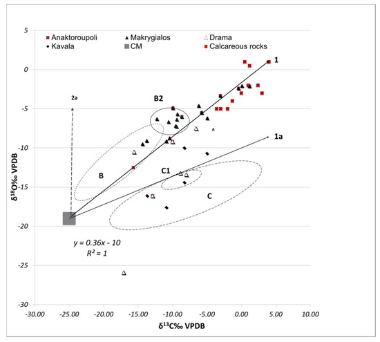
Figure 12.
Scattered diagram that summarizes the various sources of CO2 and H2O (lines) and mechanisms (areas).
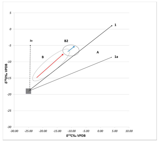
Figure 13.
The blue arrow indicates the enrichment of 18O of calcite due to the equilibrium with the silica mineral, whereas the red arrow denotes the enrichment of 18O of precipitated calcite formed from atmospheric CO2 and heavy evaporated water.
The isotopic composition of calcite from mortar represent non-isotopic equilibrium [19,20,41,42,43,44,45] and depends mainly on the isotopic composition of atmospheric CO2 and water and on the degree to which the isotopic equilibrium is reached and therefore the factor of fractionation of δ13CCaCO3 −δ13CCO2 −δ18OCO2 and δ18OH2O. In order to define the isotopic values for a pure calcite precipitated in alkaline environment using local meteoric water and atmospheric CO2, the isotopic values of local water in each sampling area are analyzed. The isotopic values of rain and spring water of the area where the ancient monuments are located are: −7.2‰18O and −45‰2H for samples from Makrygialos, −6.5‰18O and −38‰2H for samples from Kavala and −8‰18O and −65‰2H for samples from Drama [46]. Moreover, evaporation of water during the setting of the mortar gives isotopically heavier residual water. In contrary condensation effect gives isotopically lighter residual water. The origin of atmospheric CO2 for calcite formation is another important factor. It can be presumed that the isotopes of C and O of CO2 (of atmospheric origin) were stable for the last two decades. However, air pollution in not a new problem. In ancient Rome glassworkers moved outside the city centre because of environmental nuisance [47]. CO2 of biogenic origin, (combustion of coal, fuel or soil CO2) presents very low δ13C [19].
Therefore, considering the isotope fractionation of C between the CO2 (gas) and the precipitated calcite in alkaline environment the δ13Ccalcite-CO2 = δ13C calcite − δ13C CO2 = −18‰ [20] and considering that the values for δ13CCO2 range between −7‰ and −9‰, it is possible to calculate the δ13Ccalcite that is between −25‰ and −27‰. Regarding the δ18O, both the water and the CO2 oxygen contribute to the precipitated carbonate. Usdowski and Hoefs [48] and O’Neil and Barnes [41] have demonstrated that in alkaline environments, 2/3 of the oxygen in precipitated carbonate comes directly from CO2 and 1/3 of the δ18O comes from OH−. Considering the mean temperature in Makrygialos and East Macedonia and considering also the isotope fractionation between H2O and OH- (αH2O − OH− = 1.042 − 1, T = 20 °C), the value of δ18OOH- [δ18OOH− = δ18OH2O − (αH2O − OH− − 1) × 1000] is calculated between −78‰ and −80‰. Taking into consideration that the δ18O of CO2 is 10‰, (VPDB), the δ18Ocalcite is calculated (δ18Ocalcite = 1/3 × δ18OOH− + 2/3 × δ18OCO2) between −19‰ and −20‰. Therefore, such C and O isotopes values δ13Ccalcite = −25‰ to −27‰ and δ18Ocalcite = −19‰ to −20‰ (area CM in Figure 12) are typical for the precipitation of calcite by atmospheric CO2 absorption using the local isotopic composition of Drama, Kavala and Makrygialos water and atmospheric CO2.
However, the carbon and oxygen isotopic value could change due to continuous enrichment of 13C relative to 12C and of 18O relative to 16O for the CO2 gas phase and the precipitated calcite due to kinetic isotope fractionation, during calcite formation. This positive correlation of δ13C/δ18O of the formed calcite in our historical mortar made possible to determine the ideal layer from Hellenistic period and is represented by the equation δ18Ocalcite = 0.63 × δ13Ccalcite − 2 (line 1 in Figure 12). Moreover, the δ13C of mortar is also affected by the mortar mixing composition (the parts of mixing between lime, water, sand and old calcite or aggregate). If the lime is pure CaO (100%), then the carbonate formed, still has not attained a steady isotopic composition and presents δ13C and δ18O −22‰ and −20‰, respectively. These isotopic values change as the amount of charge increases (because the δ13C of old calcite is approximately 0‰) and the δ13C of carbonate formed depends on the mixing percentage of CaO and sand-old calcite. The percentage of CaO in Hellenistic samples is between 50% and 95% (Table 1). So, for a mix of equal quantities of CaO (50%) and sand-old calcite (50%), the δ13C is −9.5‰ while, when the percentage of CaO is higher due to the addition of small quantities of sand and old calcite, the δ13C of carbonate formed is more negative. Additionally, local marine limestone (Cretaceous carbonate) in the vicinity of the historical buildings, which was the main source of ancient raw material for burning, has δ13C between 0 and 3‰ and δ18O between −5‰ and −2‰ (Figure 12). Therefore, it is expected that the old mortars, which are a mixture of lime, water, sand and an aggregate like reworked brick and marble, would have δ13C > −25‰ or heavier depending on the percentage of participation of old calcite. Taking into account the percentage of CaO in Hellenistic samples the δ13C of carbonate formed will be between −25‰ and −9.5‰ depending on the participation of old calcite aggregates. In fact the Hellenistic samples show a positive correlation between δ13C and charge indicating that the shift, to more positive values can be caused by residual limestone. Consequently, the percentage of limestone used for burning or the CO2 absorption is competitive against the final value of 13C (lines 1 and 1a, Figure 12).
Mineralogical, morphological and chemical analysis indicated that the hydraulic mortars are attacked by salts while the lime-based mortars are decomposed because of the leaching action that causes material dissolution/recrystallization processes. This is depicted in Figure 12, since samples from Makrygialos are concentrated in area B2; δ18O values of these samples demonstrate continues enrichment and recrystallization tendency in O, which is related to the changes in isotopic composition because of recrystallization/dissolution mechanisms. Additionally, most of the data lie close or between on these lines indicating that the isotopic values reflect increasing δ13C values of CO2 with calcite formation along the mortar layer and the contamination by impurities of limestone relict.
However, a certain number of data (samples from Marmarion MA1-3, MA5-1 and Drama DR2g-1, DR2a-1, samples from Makrygialos and calcareous rocks) lie on or beyond of this area (area A defined by 1 and 1a lines) indicating different setting environment and secondary effects. A moderate oxygen isotopic shift is observed for samples from Makrygialos indicating that the variability of ancient water influenced the isotopic composition of calcite. Also, the oxygen values of the precipitated calcite shift to heavier values because of the evaporation of water (line 2a, area B) during the setting of mortar. Moreover, the mineralogical, morphological and chemical analysis showed that samples from Anaktoroupoli (Anp-1), Drama (DR5b-1) and some from Makrygialos (MΚ10-2, MK5) demonstrate intensive fragmentation, cracks and extensive deposition of salts that indicates later calcite alteration with actual meteoric water. There seems to be a moderate enrichment of δ18O at the surface indicating influence from rain evaporated water and from capillary suction of water. In this case the capillary transport of water was followed by evaporation when equilibrium between capillary addition of water and evaporation is reached and by salt precipitation. Thus, the major processes are dissolution of calcite and probably precipitation of other minerals (Area B2). Most of the samples lying in area B2 come from Makrygialos. SEM analysis for these samples elucidated evidence of recrystallization and material dissolution. The rest of the samples (mainly from Makrygialos) present positive oxygen isotopic shift and also significant change of the initial carbon. These isotopic values may be caused by the recrystallization of calcite with porewater and CO2 of various sources. Secondary solutions for recrystallization will be rain water and then the δ18O of calcite matrix should shift to heavier values, in our case around 0‰ similar to isotopic values of limestone. Values around 0‰, also for oxygen and carbon are attributed in the fine calcite particles (according to mineralogical, morphological and chemical analysis) in the matrix due to limestone relicts that are derived from insufficient burning. A group of data lie beyond area A indicating that precipitated calcite is formed from atmospheric CO2 and isotopically light local meteoric water or isotopically light re-condensed primary water (area C); also line 2a depicts the depletion of both isotopes indicating recrystallization of calcite with light water and CO2 of mixed origin (atmospheric and soil origin).
5. Conclusions
This work indicated that the use of isotope methods in addition to the existing “toolbox” (mineralogical, morphological, chemical analysis) of pre-restoration research methods will help to better direct safeguarding and conservation measures. The diagnostic contribution of stable isotope study traces the various sources and possible secondary processes that are responsible for the mortar degradation. Stable isotope analysis applied in combination with mineralogical, microscopic and elemental analysis provided information on the different types of mortar degradation. Mortar’s weathering was attributed to a combination of environmental threats such as salts attack and leaching action. Stable isotope analysis (13C and 18O) provided information relative to the origin of CO2 and water during calcite formation making possible to distinguish different mortar technologies and degradation gradients. Compositional and morphological analyses were achieved using energy dispersive X-ray analysis in the scanning electron microscope while the mineralogical phases were detected using petrographic (polarized optical microscopy) analysis. The results of micro-morphological and petrographic examination elucidated the technological continuity and degradation of historic mortars. Hellenistic mortars are composed of lime enhanced with quartz aggregates. Roman and Byzantine mortars are composed of hydraulic lime, pozzolan and a various aggregates such as quartz, feldspar, ceramic and lithoclasts. The main degradation mechanisms are calcite recrystallization, loose of adhesion bonds in the binding material and salts crystallization. Mortar’s weathering was also attributed to a combination of environmental threats such as salts attack and leaching action. Stable isotopes of δ18O and δ13C showed that in general there are extended dissolution/reprecipitation processes that take place on the surface layers ending in the inner structure of funerary monuments. Finally, this study indicated that stable isotope analysis is an excellent tool to fingerprint the origin of carbonate and therefore indicate the variations in mortar’s technology, the environmental setting conditions of mortar, origin of CO2 and water during calcite formation and to determine the weathering depth and the potential secondary degradation mechanisms.
Author Contributions
Conceptualization, D.E; Methodology, D.E, K.D., C.V. and D.G. Writing–Original Draft Preparation, D.E., K.D.; Writing-Editing, D.G.; Project Administration, D.E.; Funding Acquisition, D.E.
Funding
This research received no external funding.
Acknowledgments
We would like to sincerely thank Bessios at the KZ’ Ephoreia of Classical and Prehistoric antiquities for kindly providing access for sampling at Hellenistic funerary monuments. Also, Dadaki and Ioannis Iliadis at the 12th Ephoreia of Byzantine antiquities are kindly thanked for providing Byzantine and Roman mortar samples. Finally, many thanks go to Vasilios Melfos for performing petrographic analysis in mortar samples at the Department of Mineralogy, Petrology and Economic Geology in Aristotle University of Thessaloniki.
Conflicts of Interest
The authors declare no conflict of interest.
References
- Sabbioni, C.; Zappia, G.; Riontino, C.; Blanco-Varela, M.T.; Aguilera, J.; Puertas, F.; Van Balen, K.; Toumbakari, E.E. Atmospheric deterioration of ancient and modern hydraulic mortars. Atmos. Environ. 2001, 35, 539–548. [Google Scholar] [CrossRef]
- van Balen, K.; Toumbakari, E.E.; Blanco-Varela, M.T.; Aguilera, J.; Puertas, F.; Palomo, A. Environmental deterioration of ancient and modern hydraulic mortars. WIT Trans. Built Environ. 1970, 42, 10. [Google Scholar]
- Yates, T. The Effects of Air Pollution on the Built Environment. Air Pollution Reviews; Brimblecombe, P., Ed.; Imperial College Press: London, UK, 2003; pp. 107–132. [Google Scholar]
- Zappia, G.; Sabbioni, C.; Pauri, M.; Gobbi, G. Mortar damage due to airborne sulfur compounds. Mater. Struct. 1994, 27, 469–473. [Google Scholar] [CrossRef]
- Stefanidou, M.; Papayianni, I. Salt accumulation in historic and repair mortars. In Proceedings of the Heritage, Weathering and Conservation Conference, Consejo Superior de Investigaciones Cientificas, Madrid, Spain, 21–24 June 2006; Taylor & Francis: London, UK, 2006; pp. 269–272. [Google Scholar]
- Stefanidou, M. A contribution to salt crystallization into the structure of traditional repair mortars through capillarity. In Proceedings of the 11th euroseminar on microscopy applied to building materials, Porto, Portugal, 5–9 June 2007. [Google Scholar]
- Theoulakis, P.; Moropoulou, A. Microstructural and mechanical parameters determining the susceptibility of porous building stones to salt decay. Constr. Build. Mater. 1997, 11, 65–71. [Google Scholar] [CrossRef]
- Rossi-Manaresi, R.; Tucci, A. Pore structure and the disruptive or cementing effect of salt crystallization in various types of stone. Stud. Conserv. 1991, 36, 56–58. [Google Scholar]
- Scherer, G.W. Stress from crystallization of salt. Cem. Concr. Res. 2004, 34, 1613–1624. [Google Scholar] [CrossRef]
- Papayianni, I.; Stefanidou, M.; Pachta, V.; Konopisi, S. Content and topography of salts in historic mortars. In Proceedings of the 3rd Historic mortars conference, Glasgow, Scotland, 11–14 September 2013. [Google Scholar]
- Gomides, M.d.J.; Molin, D.C.C.D.; Rêgo, J.H.d.S. Effect of the incorporation of aggregates with high sulfide content on the mechanical and microstructural properties of concrete with slag cement. Matéria (Rio de Janeiro) 2017, 22. [Google Scholar] [CrossRef]
- Chinchón, J.; Ayora, C.; Aguado, A.; Guirado, F. Influence of weathering of iron sulfides contained in aggregates on concrete durability. Cem. Concr. Res 1995, 25, 1264–1272. [Google Scholar] [CrossRef]
- Clark, I.; Fritz, P. Environmental Isotopes in Hydrogeology; Lewis Publishers: Boca Raton, FL, USA, 1997. [Google Scholar]
- Craig, H. Isotopic variations in meteoric waters. Science 1961, 133, 1702–1703. [Google Scholar] [CrossRef] [PubMed]
- Maravelaki-Kalaitzaki, P.; Bakolas, A.; Moropoulou, A. Physico-chemical study of Cretan ancient mortars. Cement and Concrete Research 2003, 33, 651–661. [Google Scholar] [CrossRef]
- Moropoulou, A.; Bakolas, A.; Bisbikou, K. Investigation of the technology of historic mortars. J. Cult. Her. 2000, 1, 45–58. [Google Scholar] [CrossRef]
- Moropoulou, A.; Bakolas, A.; Bisbikou, K. Characterization of ancient, byzantine and later historic mortars by thermal and X-ray diffraction techniques. Thermochim. Act. 1995, 269, 779–795. [Google Scholar] [CrossRef]
- Bakolas, A.; Biscontin, G.; Moropoulou, A.; Zendri, E. Characterization of the lumps in the mortars of historic masonry. Thermochim. Acta 1995, 269, 809–816. [Google Scholar] [CrossRef]
- Dotsika, E.; Psomiadis, D.; Raco, B.; Poutoukis, D.; Gamaletsos, P. Isotopic analysis for degradation diagnosis of calcite matrix in mortar and plaster. Anal. Bioanal. Chem. 2009, 395, 2227–2234. [Google Scholar] [CrossRef] [PubMed]
- Kosednar-Legenstein, B.; Dietzel, M.; Leis, A.; Stingl, K. Stable carbon and oxygen isotope investigation in historical lime mortar and plaster–Results from field and experimental study. Appl. Geochem. 2008, 23, 2425–2437. [Google Scholar] [CrossRef]
- Larbi, J. Microscopy applied to the diagnosis of the deterioration of brick masonry. Constr. Build. Mater. 2004, 18, 299–307. [Google Scholar] [CrossRef]
- Hughes, J.J.; Cuthbert, S.J. The petrography and microstructure of medieval lime mortars from the west of Scotland: Implications for the formulation of repair and replacement mortars. Mater. Struct. 2000, 33, 594–600. [Google Scholar] [CrossRef]
- Deer, W.A.; Howie, R.A.; Zussman, J. An Introduction to the Rock Forming Minerals, 2nd ed.; Longman Scientific & Technical: London, UK, 1992; p. 696. [Google Scholar]
- Tucker, M.E. Sedimentary Petrology, 2nd ed.; Blackwell Scientific Publications: Hoboken, NW, USA, 1991. [Google Scholar]
- Adams, A.E.; MacKenzie, W.S.; Guildford, C. Atlas of Sedimentary Rocks Under the Microscope; Routledge: Abington, UK, 2017. [Google Scholar]
- Whitbread, I.K. The characterisation of argillaceous inclusions in ceramic thin sections. Archaeometry 1986, 28, 79–88. [Google Scholar] [CrossRef]
- Freestone, I.C. Ceramic Petrography. Am. J. Archaeol. 1995, 99, 111–115. [Google Scholar]
- Coplen, T.B; Kendall, C.; Hopple, J. Comparison of stable isotope reference samples. Nature 1983, 302, 236–238. [Google Scholar] [CrossRef]
- Coplen, T.B. Reporting of stable hydrogen, carbon and oxygen isotopic abundances (technical report). Int. Union Pure Appl. Chemi. 1994, 66, 273–276. [Google Scholar] [CrossRef]
- Coplen, T.B. Discontinuance of Smow and PDB. Nature 1995, 375, 285. [Google Scholar] [CrossRef]
- Chabas, A.; Jeannette, D. Weathering of marbles and granites in marine environment: petrophysical properties and special role of atmospheric salts. Environ. Geol. 2001, 40, 359–368. [Google Scholar] [CrossRef]
- Liu, P. Damage to concrete structures in a marine environment. Mater. Struct. 1991, 24, 302–307. [Google Scholar] [CrossRef]
- Tsouris, E.M.A. Byzantine fortifications in Evros. Byzantina 2006, 26, 153–209. [Google Scholar]
- Dadaki, S. (Greek Ministry of Culture, Athens, Greece). Historical overview of the antiquities of 12th EBA, 12th Ephoreia of Byzantine antiquities, Archaeological report. Unpublished work. 2010. [Google Scholar]
- Mpesios, M. Pieridon Stephanos: Pydna, Methone Kai Hoi Archaiotetes Tes Voreias Pierias; Anthropon Physeos Erga: Katerine, Greece, 2010. [Google Scholar]
- van Strydonck, M.J.; Dupas, M.; Keppens, E. Isotopic fractionation of oxygen and carbon in lime mortar under natural environmental-conditions. Radiocarbon 1989, 31, 610–618. [Google Scholar] [CrossRef]
- Papayianni, I.; Stefanidou, M. Strength–porosity relationships in lime–pozzolan mortars. Constr. Build. Mater. 2006, 20, 700–705. [Google Scholar] [CrossRef]
- Walker, R.; Pavía, S. Behaviour and Properties of Lime-Pozzolan Pastes. In Proceedings of the 8th International Masonry Conference 2010, Dresden, Germany, 4–7 July 2010; Jäger, W., Haseltine, B., Fried, A., Eds.; International Masonry Society: Shermanbury, UK, 2010; pp. 353–362. [Google Scholar]
- Walker, R.; Pavía, S. Physical properties and reactivity of pozzolans, and their influence on the properties of lime-pozzolan pastes. Mater. Struct. 2011, 44, 1139–1150. [Google Scholar] [CrossRef]
- Matias, G.; Faria, P.; Torres, I. Lime mortars with heat treated clays and ceramic waste: a review. Constr. Build. Mater. 2014, 73, 125–136. [Google Scholar] [CrossRef]
- O’Neil, J.R.; Barnes, I. 13C and 18O compositions in some fresh-water carbonates associated with ultramafic rocks and serpentinites: Western United States. Geochim. Cosmichim. Acta. 1971, 35, 687–697. [Google Scholar] [CrossRef]
- Pachiaudi, C.; Marechal, J.; van Strydonck, M.; Dupas, M.; Dauchot- Dehon, M. Isotopic fractionation of carbon during CO2 absorption by mortar. Radiocarbon 1986, 28, 691–697. [Google Scholar] [CrossRef]
- Rafai, N.; Letolle, R.; Blanc, P.; Gegout, P.; Revertegat, E. Carbonation–decarbonation of concretes studied by the way of carbon and oxygen stable isotopes. Cem. Concr. Res. 1992, 22, 882–890. [Google Scholar] [CrossRef]
- Dietzel, M.; Usdowski, E.; Hoefs, J. Chemical and 13C/12Cand 18O/16O-isotope evolution of alkaline drainage waters and the precipitation of calcite. Appl. Geochem. 1992, 7, 177–184. [Google Scholar] [CrossRef]
- Clark, I.D.; Fontes, J.C.; Fritz, P. Stable isotope disequilibria in travertine from high pH waters: Laboratory investigations and field observations from Oman. Geochem. Cosmchim. Acta 1992, 56, 2041–2050. [Google Scholar] [CrossRef]
- Dotsika, E.; Lykoudis, S.; Poutoukis, D. Spatial distribution of the isotopic composition of precipitation and spring water in Greece. Glob. Planet. Chang. 2010, 71, 141–149. [Google Scholar] [CrossRef]
- Taylor, R.M. Roman Builders: A Study in Architectural Process; Cambridge University Press: Cambridge, UK, 2003; pp. 175–178. [Google Scholar]
- Usdowski, E.; Hoefs, J. Oxygen isotope exchange between carbonic acid, bicarbonate, carbonate, and water: A re-examination of the data of McCrea (1950) and an expression for the overall partitioning of oxygen isotopes between the carbonate species and water. Geochim. Cosmochim. Acta 1993, 57, 3815–3818. [Google Scholar] [CrossRef]


© 2018 by the authors. Licensee MDPI, Basel, Switzerland. This article is an open access article distributed under the terms and conditions of the Creative Commons Attribution (CC BY) license (http://creativecommons.org/licenses/by/4.0/).