Abstract
Wetting of bentonite is a complex hydro-mechanical process that involves swelling and, if confined, significant structural changes in its void structure. A coupled structural transport network model is proposed to investigate the effect of wetting of bentonite on retention conductivity and swelling pressure response. The transport network of spheres and pipes, representing voids and throats, respectively, relies on Laplace–Young’s equation to model the wetting process. The structural network uses a simple elasto-plastic approach without hardening to model the rearrangement of the fabric. Swelling is introduced in the form of an eigenstrain in the structural elements, which are adjacent to water filled spheres. For a constrained cell, swelling is shown to produce plastic strains, which result in a reduction of pipe and sphere spaces and, therefore, influence the conductivity and retention behaviour.
1. Introduction
Bentonite, with montmorillonite as its main constituent, is an important material for storage of waste, because of its very low permeability and its ability to swell during the uptake of water. The swelling causes a rearrangement of the fabric, which reduces the size of large voids and throats and larger openings, such as gaps between bentonite blocks, which could otherwise act as pathways of water and gas carrying potentially harmful substances away from the stored waste. The strong interaction of the structural response (swelling and rearrangement of the fabric) and the transport response (retention behaviour and conductivity) originates from processes at multiple scales.
Commonly, mathematical multi-physics approaches are used to represent the phenomenological response at the structural scale without attempting to model explicitly the processes at lower scales [1]. These phenomenological models are very useful in predicting boundary values at the structural scale. If calibrated properly, they can be used to make predictions on the wetting process of large assemblies of bentonite blocks subjected to complex hydro-thermo-mechanical boundary conditions. However, by being phenomenological, these approaches are by design not intended to provide an improved understanding of how interactive processes on lower scales influence the structural response. For obtaining this understanding, models are required that describe explicitly the features at lower scales of bentonite, such as void shape, size, connectivity and the corresponding physical processes at these scales. The drawback of lower scale models is that, because of the complicated material structure of bentonite, they usually can only provide a qualitative description of the processes. This type of qualitative lower scale model is proposed in this study.
The fabric of bentonite depends strongly on the state of compaction. For waste disposal, bentonite is commonly installed in the form of highly compacted unsaturated blocks. In this state, the characteristics of the fabric are visible at three distinctive scales [1,2,3]. At the smallest scale, particles of a sub-micron size are made of stacks of lamellae with interlamellar spaces. Chemico-physical processes at this scale are responsible for the swelling capabilities of bentonite. At the meso-scale, these particles are arranged in porous grains of a sub millimetre size. The voids within these grains have dimensions similar to those of the individual particles averaging a few nano-meters. Finally, the macro-scale is defined as the packing of the meso-scale grains with an average macro void scale of similar dimension as the individual grains. This network of voids is called the inter-grain void network. Although wetting of the bentonite results in a significant change of these characteristics due to the rearrangement of the fabric caused by swelling-induced pressure, the overall grain structure remains intact [4].
Here, a coupled transport-structural network model is used to analyse the macro-scale of the fabric of bentonite consisting of the packing of bentonite grains. Since the pioneering work of [5], transport network models have been widely used for fluid retention and hydraulic conductivity modelling of porous materials. Authors, such as [6,7], investigated the influence of the mean coordination number, sphere and pipe size distributions and spatial correlation on retention curves and relative permeability curves, including the influence of phenomena, such as trapping and snap off. The work in [5,6,7] aimed to improve the qualitative understanding of the influence of the microstructure on the macroscopic fluid retention and transport properties of porous materials.
In [8], a transport network was applied to bentonite behaviour. However, due to the strong transport-structural coupling of the response of bentonite, transport networks alone are not sufficient to improve the qualitative understanding of the influence of the microstructure on macroscopic properties. Here, it is aimed to improve this understanding by means of a coupled transport-structural network model. The novelty of the present work is the coupling of structural and transport networks to simulate the transport-structural process of the wetting of bentonite. To the authors’ knowledge, no coupled transport-structural network approach for modelling bentonite has been proposed in the literature so far. The structural network represents the mechanical interaction of the grains, such as swelling, pressure build-up and plastic reformation, whereas the transport network describes the conductivity and retention of the void network formed by the arrangement of the grains. Transport within the grains was not modelled. Therefore, the effect of the anisotropy of the grains’ transport properties due to compaction was not considered.
Structural networks, modelling the interactions of grains/particles/rigid-bodies, have been widely used in the field of discrete modelling of geomaterials [9,10]. The most commonly-used discrete structural model assumes spherical rigid particles that are interacting through sets of springs representing the constitutive response of the material [10]. Other approaches have used, instead of spheres, rigid polyhedra connected by springs [9]. This type of network of polyhedra has been recently used to model the influence of fracture on transport in geomaterials [11].
Both the transport and structural network proposed here are simpler than many already existing approaches in the literature. However, the novel contribution of this work is the combination of transport and structural networks to provide the modelling capabilities of bentonite at the macro-scale. The focus of this work is to improve the qualitative understanding of the influence of processes on the lower scales on the macroscopic response. The approach is not designed to be used for large-scale boundary value problems. Therefore, the model presented here is not seen as a competitor to phenomenological transport-structural approaches for bentonite at the structural scale, but instead as a tool to gain a better understanding of what happens within the inter-grain void network, which can then be used, together with appropriate experiments, to improve phenomenological models.
2. Network Model
The coupled network model has been developed to describe processes at the macro-scale of initially heavily-compacted bentonite. At the macro-scale, the packing of grains of clay particles (Figure 1a) is modelled by structural and transport networks (Figure 1b). For the transport part, it is assumed that the grains do not fill the volume of the cell completely, but form spaces in the form of voids and throats, which are modelled by the transport network. A list of the symbols used in the model formulation is shown in Table 1.
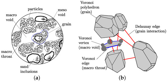
Figure 1.
Bentonite fabric: (a) macro-scale of heavily-compacted unsaturated bentonite (adapted from [1]) and (b) schematic presentation of four Voronoi polyhedra and the corresponding Delaunay tetrahedron. The spheres and pipes corresponding to a Voronoi polyhedron face are also presented. The Voronoi grains are scaled down to improve the clarity of the presentation (in the actual network, the grains are in contact).

Table 1.
Nomenclature.
The geometry of the two networks within a cell of edge length is created randomly. Firstly, points are placed randomly in the cell by means of a trial and error approach satisfying a minimum distance . If a trial point is closer than to already placed points, its position is rejected, and new trial coordinates are determined. This process is repeated until the point can be placed in the cell satisfying the requirement on the minimum distance. The more points are placed in the cell, the more iterations are needed to add a new point that is not too close to already existing points. If the placement of a new point requires more than attempts, the cell is assumed to be saturated, and the process of placing points is terminated.
Next, Delaunay and Voronoi tessellations based on the random set of points are generated [12]. The Delaunay tessellation (consisting of irregular tetrahedra with their vertices at the points) is dual to the Voronoi tessellation (consisting of irregular polyhedra, with each face of a polyhedron perpendicular to a Delaunay edge and intersecting this Delaunay edge at its mid-point). These two tessellations are used to define the geometry of the structural and transport network. For the structural network, the interactions between the grains are represented by structural elements placed on the edges of the Delaunay tetrahedra.
For the transport network, the spheres, representing voids, are placed on the polyhedra vertices and the pipes, representing throats, along the polyhedra edges. This is a suitable approach for hydro-mechanical analyses, where the polyhedra are idealisations of the material grains surrounded by voids and throats. A schematic presentation of four Voronoi polyhedra and their corresponding Delaunay edges is presented in Figure 1b, with each polyhedral grain scaled down in the figure in order to provide a clearer visual impression (in the actual network, the grains are in contact).
For the transport network, spheres and pipes have a distribution of radii, each with a log-normal probability distribution function with cut-offs. Sphere radii are allocated first, on a random basis, with no spatial correlation. Pipe radii are then allocated to locations, with the smallest radii pipes allocated first, commencing with locations connecting to the smallest spheres. In the structural network, the geometrical properties of the mid-cross-sections are defined by the geometry of the corresponding facets of the Voronoi polyhedra.
The input parameters for the generation of the two networks are the minimum distance , the number of maximum iterations , the mean of the sphere radii , the coefficient of variation of the sphere radii , the mean of the pipe radii and the coefficient of variation of the pipe radii . Furthermore, minimum values of the sphere and pipe radii, , , are required to avoid numerical problems created by too small spheres and pipes.
2.1. Transport Network
The retention and conductivity of a representative cell of bentonite is modelled by a network of pipes and spheres (Figure 1b) [13]. Only the properties of the pipes determine the conductivity of the network, whereas both pipes and spheres are involved in the retention behaviour. The network will be used to determine the properties of a representative cell, which is subjected to monotonically-decreasing capillary suction applied uniformly across the cell during the wetting process. At the scale of a boundary value problem, gradients of capillary suction are commonly present, which are the driving force for the ingress of water causing a wetting process. However, these gradients are not considered at the level of the representative cell of the macro-scale. Instead, the conductivity of the cell is determined by separately applying a numerical water pressure gradient across the cell, which is independent of the uniform capillary suction used to control the wetting process. In the following sections, the individual parts of the transport network are described.
2.1.1. Transport Element Formulation
The transport through pipes is determined by a mass balance equation. The discrete equation for a pipe is:
where is the vector of water pressures at the nodes of the element, is the vector of the nodal flow rate and is the conductivity matrix. The pressures are the result of the numerically-applied pressure gradient, which is used to determine the conductivity of the cell. It is independent of the uniform capillary suction that is used to control the wetting process of the cell. The conductivity matrix is evaluated as:
where k is the conductivity, is the pipe radius and is the length of the pipe. The conductivity k has two possible values depending on the type of fluid present in the pipe. If the pipe is filled with wetting fluid, i.e., the spheres at both ends of the pipe are filled with wetting fluid, the conductivity is equal to the wetting fluid conductivity . On the other hand, if the pipe is filled with a non-wetting fluid, i.e., at least one of the two spheres is not filled with the wetting fluid, the conductivity is equal to the vapour conductivity . For the study of the wetting of bentonite, the wetting fluid is considered to be water and the non-wetting fluid to be air containing water vapour. The conductivity of a water filled pipe is based on the Hagen–Poiseuille equation [14]:
where ρ is the density of the water and μ the dynamic viscosity. The conductivity of the vapour filled pipe is:
where is the density of the saturated vapour, the molecular diffusivity for vapour through air, M the molar mass of the vapour, R the universal gas constant and T the temperature [15]. Transport due to vapour diffusion in a vapour-filled pipe was approximated by a conductivity and flow driven by a water pressure gradient by considering Kelvin’s law, which states that under equilibrium conditions across a liquid-vapour interface, the relative humidity of the vapour phase (i.e., the vapour concentration) is related to the capillary suction (i.e., to the water pressure, since air is assumed to be at uniform pressure).
2.1.2. Void Volume Scaling
For a material with a wide range of void sizes, a cell would require a very large number of smaller voids in order to also include a statistically representative number of larger voids. With a standard network, this would require a cell with an impractically large number of spheres. In addition, a standard network could not capture the fact that the average centre-to-centre spacing of smaller voids should be much less than the corresponding spacing for larger voids; otherwise, adjacent small voids would be unreasonably far apart (suggesting an exceptionally low local porosity), and two adjacent large voids would be impossibly close together (suggesting the overlap of the two voids).
In order to avoid these problems, a new approach was introduced, where each sphere within the network represents a scaled number of voids, with this scaling number increasing as the sphere size reduces. The scaling number is:
where is the radius of the sphere, is the initial radius of the sphere and is the mean initial radius of the spheres. In the case of reactive transport, as here for the wetting process of bentonite, the radius of individual spheres changes during the analysis because of swelling strain applied to the structural elements. To be able to use the volume scaling for reactive transport, N in Equation (5) is determined for the initial radius and then kept constant during the analysis.
Equation (5) means that each sphere of initial radius smaller than the mean represents more than a single void, whereas each sphere of initial radius greater than the mean represents less than one void. This scaled number of voids means that each sphere represents a volume of voids given by:
For , the expression for the volume in Equation (6) reduces to:
Thus, for the case where sphere radii are unchanging (), each sphere represents the same volume of voids, whatever its radius. The volume of pipes is ignored in calculating the porosity or degree of saturation of the cell, and therefore, the porosity n of a cubical cell of side length containing a total of m spheres is given by:
which, for , simplifies to:
The advantage of the void volume scaling approach is that the network model is able to represent a cell containing a large number of small voids without excessive computational effort. In addition, local values of porosity internally within the cell are realistic, rather than being unreasonably low in regions around smaller spheres and impossibly high in regions around the largest spheres. A disadvantage of the void volume scaling approach is, however, that modelling of connectivity between voids, which is always imperfectly represented in a network model, may be represented less realistically than without scaling. This can be illustrated by considering the case of a sphere that is significantly smaller than the mean sphere radius . This sphere represents a substantial number N of voids, rather than a single void. The scaling technique means that local connectivity between these N voids is overstated, as they are all assumed to be at the same location in the network and are therefore perfectly connected to each other. In contrast, external connectivity between these N voids and other voids is understated, as only four pipes connect the single sphere representing all of these N voids to other spheres. Reverse arguments apply to voids that are larger than the mean radius.
2.1.3. Modelling Retention Behaviour
Capillary suction , applied uniformly throughout the cell, was the driving variable for wetting of the cell. The capillary suction is defined as , where is the pressure in the air and is the pressure in the water. Here, is assumed to be equal to the atmospheric pressure. The applied value of was monotonically decreased during the wetting process.
The rules that determine, for a given value of , which spheres are filled with the wetting and non-wetting fluid, respectively, are based on the Young–Laplace equation:
where γ is the surface tension and θ is the contact angle formed between the fluid-fluid interface and the solid (measured on the wetting fluid side). Furthermore, r is the radius of a pipe during a drying process and the radius of a sphere during a wetting process, to represent the so-called “ink bottle” effect. A drying or wetting process is modelled by considering the intruding fluid moving from a void already filled with that fluid to a connected void not previously filled with that fluid, i.e., direct connection to a void already filled with the intruding fluid is imposed as a requirement for a void to fill with the intruding fluid. The drying fluid is the intruding fluid during a drying path, whereas the wetting fluid is the intruding fluid during a wetting path. Figure 2a illustrates the situation during a drying process. The hatched area corresponds to the wetting fluid. The drying fluid has already intruded through Pipe 1 into sphere A at a value of corresponding to the application of Equation (10) with r as the radius of Pipe 1. As the value of is increased further during the drying process, the next consideration is when the drying fluid will intrude further from sphere A along either Pipe 2 or Pipe 3. Pipe 2 is of a larger radius than Pipe 3, and therefore, the first action to occur is the intrusion of the drying fluid along Pipe 2 and into sphere B, at a value of corresponding to the application of Equation (10) with r as the radius of Pipe 2. If either Pipe 4 or Pipe 6 was larger than Pipe 2, the intrusion would continue along this pipe into an additional sphere without the need for the further increase of .
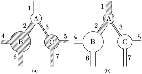
Figure 2.
Retention behaviour: A simple 2D network subjected to (a) drying and (b) wetting. The hatched areas represent the wetting fluid. The drying and wetting fluid for cases (a) and (b), respectively, is allowed to enter the network from Pipe 1.
Figure 2b illustrates an equivalent situation for a wetting process, with the hatched area again representing the wetting fluid. Wetting fluid has already entered sphere A from Pipe 1, at a value of corresponding to the application of Equation (10) with r as the radius of sphere A, and immediately moved into Pipes 2 and 3. As the value of is reduced further during the wetting process, the next consideration is when the wetting fluid will intrude into sphere B or sphere C. As sphere C is smaller than sphere B, the first thing that happens is intrusion of the wetting fluid into sphere C, at a value of corresponding to the application of Equation (10), with r as the radius of sphere C, and immediate further movement of the wetting fluid into Pipes 5 and 7. If either Pipe 5 or Pipe 7 is connected to an additional sphere that was smaller than sphere C, the wetting fluid would continue into this sphere without the need for a further decrease of .
At each value of during a drying or wetting process, the degree of saturation (expressed in terms of the wetting fluid) is calculated by considering the proportion of spheres filled with the wetting fluid. Hence, if m is the total number of spheres in the cell and is the number of these spheres filled with the wetting fluid, the degree of saturation is given by:
In analysing drying and wetting processes, no possibility of trapping of the non-intruding fluid is considered, because there is no consideration of whether there is appropriate connectivity to provide an exit route for the non-intruding fluid (connectivity requirements are applied to the intruding fluid, but not to the non-intruding fluid). In practice, trapping of the non-intruding fluid is not an issue if the non-intruding fluid can escape by diffusing through the intruding fluid and provided that drying or wetting is performed sufficiently slowly for the diffusion process to dissipate excess pressure in the trapped non-intruding fluid.
In addition to the geometrical input parameters related to the size distributions of spheres and pipes described in Section 2.1, additional input parameters are required related to the fluids and their interaction with the void network. For water, the parameters are the density ρ, the absolute (dynamic) viscosity μ, the contact angle θ and the surface tension γ. For the vapour, the parameters are the saturated vapour density ρ, the water vapour diffusivity , temperature T, universal gas constant R and water molecular weight M. All of these parameters have a strong physical meaning with input values that can be found in the literature.
The present transport network has a constant coordination number of four. Smaller coordination numbers could be introduced by deleting spheres, as was proposed in [16]. However, a coordination number greater than four would not be possible for the present dual Delaunay–Voronoi tessellations used for the generation of the coupled transport-structural networks.
2.2. Structural Network
The structural network simulates the interaction of the grains. It is based on a network model developed originally for predicting the interaction of discontinuous blocks in [17] and was applied to polyhedra in [11,18]. The discrete equilibrium equation for the structural element shown in Figure 3a is:
where is the stiffness matrix, are the nodal degrees of freedom and are the acting forces.
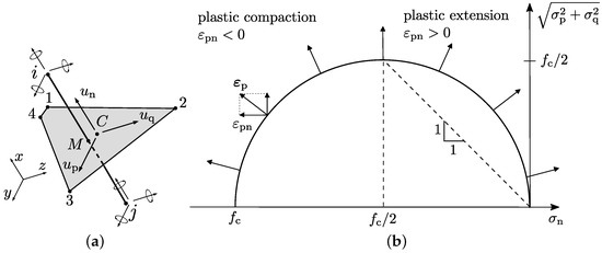
Figure 3.
Structural network: (a) structural element with nodal degrees of freedom and displacement discontinuities at the mid-cross-section and (b) the spherical yield surface for the modelling of plastic deformation.
Each node has three translational (, and ) and three rotational (, and ) degrees of freedom. These degrees of freedom are used to determine displacement discontinuities at point at the mid-cross-section of the element by rigid body kinematics [17] (Figure 3a). The displacement jump is transformed into strains , where h is the length of the structural element, i.e., the distance between nodes i and j. The strains are related to stresses by means of an elasto-plastic constitutive model. The stress-strain law is:
where is the mechanical strain that is calculated from the total strain ε and plastic strain as . Furthermore, is the swelling strain, and is a stress due to the presence of a meniscus bridge between the grains, which is discussed in Section 2.3. Finally, the elastic material stiffness , where E is the Young’s modulus of the material. The plastic strains are determined using the standard framework for elasto-plasticity without hardening with a spherical yield surface shown in Figure 3b and an associated flow rule. The yield surface is capped by the compressive strength (Figure 3b) so that for large negative normal stresses, the normal component of the plastic flow is negative, which corresponds to plastic shortening of the grain interaction. The plasticity model does not provide any cohesion. However, the stress due to the meniscus between the grains provides the material with apparent cohesion.
The plasticity model with its limit on the compressive strength is used to describe the rearrangement of the bentonite fabric when it undergoes restrained swelling. For instance, for a structural element that is constrained to have a constant length, a positive swelling strain produces a negative mechanical strain, which results in a plastic shortening of the grain interaction. This plastic shortening affects the transport network as described in Section 2.3. The input parameters of the structural model are Young’s modulus E, compressive strength and the swelling strain . Here, estimates of E and for bentonite are based on the range of experimental results available in the literature. The swelling strain is the main parameter that will be investigated in the present study in Section 3.
2.3. Coupling
The transport and structural networks are fully coupled, i.e., the structural network is influenced by transport, and the transport network is influenced by the structural response. The structural network is influenced by the transport network in two ways. Firstly, the swelling strain in Equation (13) is only non-zero when the mid-cross-section of the structural element contains a sphere that is water filled (Figure 4a). If all of the spheres of the mid-cross-section are empty, the swelling strain is zero. With this switch condition for the swelling strain, it is assumed that the swelling of the grains occurs much faster than the wetting process modelled in the analysis, which is acceptable since wetting is modelled to be capillary suction controlled. If the transport network is subjected to wetting, more spheres are filled with water. Consequently, more mechanical elements have a sphere filled with water located at its mid-cross-section, and therefore, the total swelling of the cell increases.
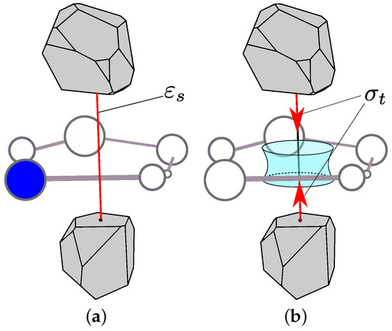
Figure 4.
Coupling between the structural and transport network: (a) swelling strain is present if one of the spheres at mid-cross-section is water filled, and (b) the meniscus generates extra forces acting on the grain interaction if all spheres at the mid-cross-section are empty.
Secondly, if all spheres on the mid-cross-section are empty, a meniscus ring forms, which results in an additional stress component (Figure 4b). Here, , where is the area of the structural mid-cross-section. This expression for the stress component is based on an approximation of the derivation in [19]. When the network is at the lowest value of , almost all elements have all their mid-cross-section empty. This results in the application of the extra normal stress for all of these elements, and therefore, the cell is shrunken due to the strains generated.
The transport model is influenced by the structural network through the formation of plastic strains, which change both the pipe and sphere radii as:
where is the initial radius and and are the plastic strain and length of the i-th element that surrounds the pipe or sphere under consideration. For the pipes, the plastic strain in the three neighbouring structural elements is used to determine the change of the radius (Figure 5a). For the spheres, the plastic strains of the four neighbouring structural elements are used in Equation (14) as shown in Figure 5b. If r calculated from Equation (14) for either a pipe or a sphere is less than the minimum radius , then the minimum radius is used in the computation.
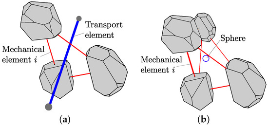
Figure 5.
Coupling between structural and transport network: influence of plastic strains on (a) the pipes and (b) the spheres.
The coupling is implemented using a marching staggered approach without iterating between the transport and structural analyses. For each step, first the transport and then the structural analysis is carried out. For instance, at step t, new spheres are filled with wetting fluid. Then, at step , the structural analysis uses the information from the transport part at step t to update the distribution of swelling strains, which leads to the formation of plastic strains. Only at step do these plastic strains affect the transport response.
3. Analyses and Results
In the present section, the coupled network model was applied to analyse the wetting of a bentonite cell subjected to the constraint of average zero normal strains in all principal directions. The numerical analyses were performed with OOFEM, an open-source object-oriented finite element program [20] extended by the present authors.
With the present model, the cell size is much smaller than a realistic boundary value problem. Therefore, it was decided to use instead a periodic cell with a periodic material structure and periodic boundary conditions. Traditional techniques for applying periodic boundary conditions (PBC), using Lagrange multipliers or four driving nodes, are not well suited for irregular networks. In these techniques, the networks are forced to be aligned with respect to the boundary, which potentially introduces boundary effects. Instead, a different PBC technique was used. This technique was presented in [21] for structural network elements in a 3D domain. The novelty of the technique is that the elements are allowed to cross the boundaries of the cell. Furthermore, each element that crosses the boundary has at least one other element that is periodic to (has the same length and orientation and is surrounded by dual edges that have identical geometry) that crosses the cell boundary at another point located diagonally or longitudinally. As a consequence, networks can maintain their random geometry while having a periodic structure. In the current work, this was extended to 3D structural and transport networks. This PBC approach requires special treatment of the network construction, because the elements are allowed to cross the cell boundaries. An example of a 3D periodic transport and structural network is presented in Figure 6. The pipes (blue) and the structural elements (yellow) cross the cell boundaries indicated by the black edges of the cell.
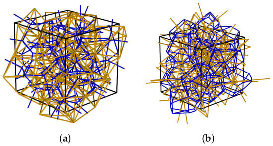
Figure 6.
Periodic cell: (a) transport elements (blue) with cross-section structural elements (yellow) and (b) structural elements (yellow) with cross-section transport elements (blue). For the reference of the colours, the reader is referred to the online version of the manuscript.
With the use of PBC, it is not possible to start a drying path from a fully-saturated condition () or a wetting path from a fully-dry condition (), because there is no external boundary from which to introduce the intruding fluid. Instead, a drying path must start with at least one sphere within the cell already filled with the drying fluid, and a wetting path must start with at least one sphere already filled with the wetting fluid. The investigation showed that realistic modelling of a drying or wetting path could not be achieved by starting with only a single sphere filled with the intruding fluid, because of the extremely low connectivity (only four pipes) from a single sphere and the consequent possibility that extreme changes of might be required for the intruding fluid to break out from this first sphere (dependent on only the radii of the four pipes in the case of a drying path or the radii of the four spheres on the other ends of these pipes in the case of a wetting path) or to break out from the local region immediately surrounding the first sphere. In order to achieve realistic modelling, drying or wetting paths should start with a small number of spheres already filled with the intruding fluid, and these “seeding” spheres should not simply be selected at random. Instead, to achieve realistic modelling of a drying path, it should always be preceded by modelling of a previous wetting path finishing with a small number of spheres (the seeding spheres) still filled with the drying fluid. A similar condition applies for realistic modelling of a wetting path, which should always be preceded by the modelling of a previous drying path to leave an appropriate number of seeding spheres filled with the wetting fluid. Investigation of this initiation process allowed an appropriate value to be selected for the number of seeding spheres (and hence, the appropriate maximum starting value of for realistic modelling of a drying path or appropriate minimum starting value of for realistic modelling of a wetting path). This was confirmed by the fact that on subsequent cycling between these maximum and minimum values of , each cycle concluded with exactly the same configuration of spheres filled with the drying fluid. In the present analyses, the volume of seeding voids was selected as 1% of the total void volume.
For the transport analyses, the specimen was initially dry, i.e., 99% of the volume of spheres was empty. It was then subjected to wetting by gradually decreasing the capillary suction . For the structural analyses, the periodic cell was subjected to zero average strain in the three directions, simulating a constrained volume experiment. At different values of , the transport network was subjected to a numerical water pressure gradient to determine the conductivity of the cell. All of the input parameters for the analyses are presented in Table 2. The input parameters related to the network generation are used as part of a parametric investigation of the present network model in [22]. Although there is no direct connection to the material structure of bentonite measured in experiments, it is assumed that these input parameters are also suitable for the present qualitative study. The material inputs for the structural model and E are in the range of typical values for compacted bentonite. Furthermore, the swelling strain was varied in this study as , , , and .

Table 2.
Input values.
The retention behaviour obtained from the transport analyses are presented in the form of saturation versus capillary suction in Figure 7.
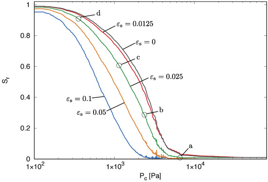
Figure 7.
Constrained swelling analysis: retention in the form of saturation versus capillary suction . The labels a, b, c and d mark stages at which the spatial distribution of quantities within the cell is investigated.
For , the response of an inert network without changing the sphere and pipe diameters is obtained, since without swelling, no plastic strains are produced. This is equivalent to the case of a transport network, which is not coupled with a structural network. As the capillary suction decreases, the number of water-filled spheres increases, and therefore, the saturation increases, as well. This is the standard response of porous materials. Full saturation is obtained in the analysis when 99% of the spheres is water filled. For the other analyses with , swelling has a significant influence on the water retention. With increasing swelling strain, the saturation increases slower for the wetting process. This is explained by the coupling between the transport and structural networks. As wetting occurs and spheres are filled with water, structural elements are subjected to the swelling strain. However, the structural network is restrained. Therefore, the swelling strains result in compressive stresses and plastic yielding. The plastic strains generated by the yielding are reducing the size of pipes and spheres. Since the degree of saturation is defined as the volume of water-filled spheres divided by the total volume of spheres, the reduction of the radii of the water-filled spheres due to swelling causes a reduced value of degree of saturation.
The conductivity versus capillary suction is shown in Figure 8 for the five different swelling strains.
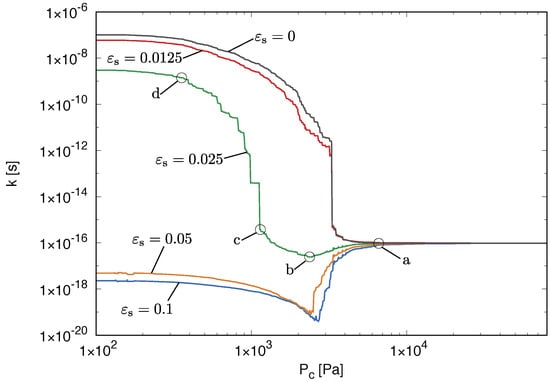
Figure 8.
Constrained swelling analysis: conductivity versus capillary suction for the large network. The labels a, b, c and d mark stages at which the spatial distribution of quantities within the cell is investigated.
The amount of swelling has a very significant effect on the conductivity. Without swelling, the conductivity increases with decreasing capillary suction, which is the expected behaviour for an inert porous material, since an increasing number of pipes is filled with water, and the fluid is transported using the larger water conductivity instead of the smaller diffusion conductivity. However, the presence of swelling changes this response dramatically. For the large swelling strains (, , ), the conductivity decreases initially and then increases again. The decrease is caused by a reduction of the pipe radii. However, this is counteracted by the increase of the number of water-filled pipes. Qualitatively, this non-monotonic evolution of the conductivity has been reported in experiments of bentonite wetting in [4].
Finally, the pressure build up due to the swelling strain in the structural network is shown in Figure 9.
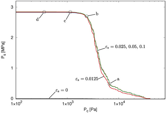
Figure 9.
Constrained swelling analysis: swelling pressure versus capillary suction . The labels a, b, c and d mark stages at which the distribution of quantities within the cell are discussed later.
The smaller the capillary suction, the greater is the swelling pressure, because more structural elements are subjected to the swelling strain. There is not much difference in the responses for the different swelling strains (provided ), because the swelling strain is for all cases other than large enough to result directly in yielding of the affected structural elements. Once yielding occurs the amount of plastic flow does not influence the pressure build up, since a perfect plasticity model is used. However, as seen in Figure 7 and Figure 8, the amount of plastic strain strongly affects the transport properties.
In the model, swelling of an element occurs only if one of the spheres of the mid-cross-section is filled with water. Since each sphere is associated with many mid-cross-sections, swelling of the elements in the cell occurs before all spheres are filled with wetting fluid. Therefore, the maximum swelling pressure in Figure 9 is reached already at around 1000 Pa, while in Figure 7, the cell is saturated only at around 100 Pa. The early build up of the swelling pressure explains also the second part of the conductivity evolution in Figure 8. When the swelling is completed at 1000 Pa, many of the pipes are still not filled with water. A pipe is only considered to be filled with water if the spheres at both ends of the pipe are filled with water. For capillary suctions of 1000 Pa and less, the radii of the pipes remain constant, since the swelling process is completed and no new plastic processes occur, which would change the radii. However, a further decrease of the capillary suction results in additional pipes being filled with water, which increases the conductivity (see Section 2.1.1). This explains the strong increase of the conductivity in Figure 8 for capillary suctions of less than 1000 Pa. The greater the swelling strain is, the greater is the reduction of the pipe and sphere radii, because greater plastic strains are produced. The smaller the radius is, the smaller is the difference between the conductivity of water-filled pipes and vapour-filled pipes. Therefore, the increase of the conductivity in Figure 8 for capillary suctions less than 1000 Pa for the swelling strains , is much less than for the other smaller swelling strains.
The above explanations are based on the evolution of macroscopic properties, such as retention, conductivity and swelling pressure. The coupled network model allows also for a more detailed insight into the response of the system by studying the evolution of internal variables within the cell, such as the distribution of water-filled pipes and radii, as well as structural elements with plastic and swelling strains. Here, the cell with is studied for the four stages marked in Figure 7 to Figure 9 as (a) to (d). Firstly, the spatial distribution of pipes filled with wetting fluid are shown in Figure 10 at the four stages (a) to (d) marked in Figure 7 to Figure 9.

The smaller the capillary suction is, the greater is the number of spheres filled with wetting fluid. For instance, from stage (b) to stage (c), there is a significant increase of the number of wetting fluid-filled pipes in Figure 10. For , this results in a significant increase of conductivity in Figure 8, assuming that the distribution of water-filled pipes for is similar to the case of . However, for a swelling strain , this increase of the number of water-filled pipes is accompanied by an initial reduction of the conductivity. This reduction in conductivity is explained by the evolution of the radii in the cell. In Figure 11, the spatial distribution of pipes with m is shown.

With decreasing capillary suction, the number of pipes with m decreases due to swelling-induced plastic strains, which explains the reduction in conductivity discussed above. The decrease in pipe radii is caused by the plastic strains in the structural network. These plastic strains are produced by the swelling pressure, which only acts on elements that have at least one water-filled sphere at the mid-cross-section. Since the spheres are filled heterogeneously within the cell, the cell is also subjected to a heterogeneous distribution of swelling strains. These heterogeneously-introduced swelling strains generate plastic strains in certain structural elements, which then cause a change in the radius of spheres.
The results presented above show that the interaction of the responses of transport and structural networks are capable of predicting the non-monotonic conductivity evolution. In [22], it was attempted to model the restrained swelling-induced change of conductivity by means of a transport network alone by reducing the radii of pipes and spheres if they are filled with water. However, with the transport network alone, it was not possible to reproduce the non-monotonic conductivity evolution.
4. Conclusions
A coupled structural transport network model for the wetting of bentonite has been proposed. The aim of the present work was to improve the understanding of the influence of lower scale processes on the macroscopic material response of bentonite. The influence of the swelling strain on the transport, retention and the swelling pressure evolution was investigated for wetting under constant volume by means of a cell with periodic boundary conditions.
The main conclusions from this work are the following:
- Constrained swelling results in the model in a significant change of the retention behaviour, because plastic strains generated due to the swelling reduce the radii of water-filled spheres. The greater the swelling strain is, the smaller is the increase of saturation for the same decrease of capillary suction.
- The constrained swelling results in an initial reduction of conductivity followed by a subsequent increase, because the swelling that results in a change of pipe radii is completed before all of the pipes are water filled. This non-monotonic evolution in conductivity is qualitatively in agreement with the experiments. In the model, the greater the swelling strains, the greater is the initial reduction in conductivity.
- The build up of swelling pressure is not strongly influenced in the model by the magnitude of the swelling strain, as long as the swelling strain is large enough to cause plastic yielding.
The improved understanding provided by the present modelling approach can be used to enhance hydro-mechanical continuum approaches at the structural scale so that they can be applied with greater confidence to situations for which the models have not been calibrated. Possible extensions of the mode would be the inclusion of thermal effects. Furthermore, the model could be applied to wetting and drying cycles.
Acknowledgments
The authors acknowledge funding received from the U.K. Engineering and Physical Sciences Research Council (EPSRC) under Grant EP/I036427/1 and funding from Radioactive Waste Management Limited (RWM), a wholly-owned subsidiary of the Nuclear Decommissioning Authority. RWM is committed to the open publication of such work in peer-reviewed literature and welcomes e-feedback to rwmdfeedback@nda.gov.uk.
Author Contributions
All authors developed the model and wrote the paper.
Conflicts of Interest
The authors declare no conflict of interest.
References
- Gens, A.; Alonso, E.E. A framework for the behaviour of unsaturated expansive clays. Can. Geotech. J. 1992, 29, 1013–1032. [Google Scholar] [CrossRef]
- Alonso, E.E.; Vaunat, J.; Gens, A. Modelling the mechanical behaviour of expansive clays. Eng. Geol. 1999, 54, 173–183. [Google Scholar] [CrossRef]
- Delage, P.; Marcial, D.; Cui, Y.; Ruiz, X. Ageing effects in a compacted bentonite: A microstructure approach. Géotechnique 2006, 56, 291–304. [Google Scholar] [CrossRef]
- Wang, Q.; Cui, Y.J.; Tang, A.M.; Barnichon, J.; Saba, S.; Ye, W.M. Hydraulic conductivity and microstructure changes of compacted bentonite/sand mixture during hydration. Eng. Geol. 2013, 164, 67–76. [Google Scholar] [CrossRef]
- Fatt, I. The network model of porous media: I. Capillary pressure characteristics. Pet. Trans. AIME 1956, 207, 144–163. [Google Scholar]
- Tsakiroglou, C.D.; Payatakes, A.C. A new simulator of mercury porosimetry for the characterization of porous materials. J. Colloid Interface Sci. 1990, 137, 315–339. [Google Scholar] [CrossRef]
- Jerauld, G.; Salter, S. The effect of pore-structure on hysteresis in relative permeability and capillary pressure: Pore-level modeling. Transp. Porous Media 1990, 5, 103–151. [Google Scholar] [CrossRef]
- Xiong, Q.; Jivkov, A.P.; Yates, J.R. Discrete modelling of contaminant diffusion in porous media with sorption. Microporous Mesoporous Mater. 2014, 185, 51–60. [Google Scholar] [CrossRef]
- Kawai, T. New discrete models and their application to seismic response analysis of structures. Nucl. Eng. Des. 1978, 48, 207–229. [Google Scholar] [CrossRef]
- Cundall, P.A.; Strack, O.D.L. A discrete numerical model for granular assemblies. Géotechnique 1979, 29, 47–65. [Google Scholar] [CrossRef]
- Grassl, P.; Bolander, J. Three-dimensional network model for coupling of fracture and mass transport in quasi-brittle geomaterials. Materials 2016, 9, 782. [Google Scholar] [CrossRef]
- Okabe, A.; Boots, B.; Sugihara, K.; Chiu, S.N. Spatial Tessellations: Concepts and Applications of Voronoi Diagrams; Wiley: New York, NY, USA, 2000. [Google Scholar]
- Athanasiadis, I.; Wheeler, S.; Grassl, P. Network modelling of fluid retention behaviour in unsaturated soils. In Proceedings of the 3rd European Conference on Unsaturated Soils—”E-Unsat 2016”, Paris, France, 12–14 September 2016.
- Yiotis, A.G.; Stubos, A.K.; Boudouvis, A.G.; Tsimpanogiannis, I.N.; Yortsos, Y.C. Pore-network modeling of isothermal drying in porous media. Transp. Porous Media 2005, 58, 63–86. [Google Scholar] [CrossRef]
- Edlefsen, N.E.; Anderson, A.B.C. Thermodynamics of Soil Moisture; University of California: Oakland, CA, USA, 1943. [Google Scholar]
- Xiong, Q.; Jivkov, A.P. Analysis of pore structure effects on diffusive transport in Opalinus clay via pore network models. Mineral. Mag. 2015, 79, 1369–1377. [Google Scholar] [CrossRef]
- Kawai, T. New element models in discrete structural analysis. J. Soc. Nav. Archit. Jpn. 1977, 141, 187–193. [Google Scholar] [CrossRef]
- Yip, M.; Mohle, J.; Bolander, J.E. Automated modeling of three-dimensional structural components using irregular lattices. Comput.-Aided Civ. Infrastruct. Eng. 2005, 20, 393–407. [Google Scholar] [CrossRef]
- Fisher, R. On the capillary forces in an ideal soil; correction of formulae given by WB Haines. J. Agric. Sci. 1926, 16, 492–505. [Google Scholar] [CrossRef]
- Patzák, B. OOFEM—An object-oriented simulation tool for advanced modeling of materials and structures. Acta Polytech. 2012, 52, 59–66. [Google Scholar]
- Grassl, P.; Jirásek, M. Meso-scale approach to modelling the fracture process zone of concrete subjected to uniaxial tension. Int. J. Solids Struct. 2010, 47, 957–968. [Google Scholar] [CrossRef]
- Athanasiadis, I. Hydro-Mechanical Network Modelling of Porous Geomaterials. Ph.D. Thesis, University of Glasgow, Glasgow, UK, 2016. [Google Scholar]
- Daugherty, R.L.; Franzini, J.B. Fluid Mechanics, with Engineering Applications, 7th ed.; McGraw-Hill Kogakusha: Tokyo, Japan, 1977. [Google Scholar]
- Thomas, H.R.; He, Y. Analysis of coupled heat, moisture and air transfer in a deformable unsaturated soil. Géotechnique 1995, 45, 677–689. [Google Scholar] [CrossRef]
- Haghi, A.K. Factors effecting water-vapor transport through fibers. Theor. Appl. Mech. 2003, 30, 277–309. [Google Scholar] [CrossRef]
© 2016 by the authors; licensee MDPI, Basel, Switzerland. This article is an open access article distributed under the terms and conditions of the Creative Commons Attribution (CC-BY) license (http://creativecommons.org/licenses/by/4.0/).