Review

State-of-the-Art Review and Prospect of Modelling the Dynamic Fracture of Rocks Under Impact Loads and Application in Blasting

1
School of Engineering, University of Tasmania, Hobart, TAS 7005, Australia
2
Faculty of Engineering, Hokkaido University, Sapporo 060-8628, Hokkaido, Japan
3
School of Resources and Civil Engineering, Northeastern University, Shenyang 110819, China
*
Author to whom correspondence should be addressed.
Geosciences 2025, 15(8), 314; https://doi.org/10.3390/geosciences15080314
Submission received: 30 June 2025 / Revised: 30 July 2025 / Accepted: 6 August 2025 / Published: 12 August 2025
(This article belongs to the Section Geomechanics)

Abstract

The dynamic fracture of rocks under impact loads has many engineering applications such as rock blasting. This study reviews the recent achievements of investigating rock dynamic fracturing and its application in rock blasting using computational mechanics methods and highlights the prospects of modelling them with a hybrid finite-discrete element method (HFDEM) originally developed by the authors. The review first summarizes the peculiarities of rock dynamic fracturing compared with static fracturing, which are that the physical-mechanical properties of rocks, including stress wave propagation, strength, fracture toughness, energy partition and cracking mechanism, depend on loading rate. Then the modelling of these peculiarities and their applications in rock blasting using fast developing computational mechanics methods are reviewed with a focus on the advantages and disadvantages of prevalent finite element method (FEM) as representative continuum method, discrete element method (DEM) as representative discontinuum method and combined finite-discrete element (FDEM) as representative hybrid method, which highlights FDEM is the most promising method for modelling rock dynamic fracture and blasting application as well as points out the research gaps in the field of modelling the dynamic fracture of rocks under impact loads. After that, the progress of shortening some of these gaps by developing and applying HFDEM, i.e., the authors’ version of FDEM, for modelling rock dynamic fracture and applications in rock blasting are reviewed, which include the features of modelling the effects of loading rate; stress wave propagation, reflection and absorbing as well as stress wave-induced fracture; explosive-rock interaction including detonation-induced gas expansion and flow through fracturing rock; coupled multiaxial static and dynamic loads; heterogeneous rock and rock mass with pre-existing discrete fracture network; and dynamic fracturing-induced fragment size distribution. Finally, the future directions of modelling the dynamic fracture of rocks under impact loads are highlighted and a systematic numerical approach is proposed for modelling rock blasting.

1. Introduction

Rock dynamics has become a rapidly evolving specialization since ISRM (International Society for Rock Mechanics and rock engineering) Commission on Rock Dynamics was founded in 1983. As a sub-specialization of the rock dynamics, the dynamic fracture of rocks under impact loads has many practical applications in civil, mining, environmental and energy engineering such as tunnelling, construction, blasting, earthquakes and percussive drilling. Recent developments of theoretical, experimental and numerical methodologies have greatly advanced our understanding of the dynamic fracture of rocks under impact loads and its application. However, there is still a lack of widespread guidance and established criteria regarding the dynamic fracture of rocks under impact loads and its application [1]. Correspondingly, this study focuses on reviewing recent achievements and prospects of investigating the dynamic fracture of rocks under impact loads and its application using computational mechanics methods but is not intended to comprehensively review the recent developments of rock dynamic theoretical and experimental techniques, computational mechanics methods, or blasting application, which can be found in excellent reviews conducted by Zhang and Zhao [1], Mohammadnejad et al. [2] and An et al. [3], respectively.

2. Peculiarities of Dynamic Fracture of Rocks Under Impact Loads

This section firstly distinguishes dynamic fracture of rocks under impact loads from rock fracture under static loads on the basis of their loading strain rates and then reviews the peculiarities of rock fracture under dynamic loads compared to those under static loads, which include the responses of rock physical-mechanical properties, such as stress wave propagation, strength, fracture toughness, energy partition and crack propagation, to increasing loading rates.
In the realm of solid mechanics, the loading rate of testing methods affects the mechanical properties of different brittle materials. A comprehensive examination of the testing methods with various loading rates and their practical use in investigating various materials, including rock, concrete, ceramics and mortar has been conducted by many researchers [1,4,5,6,7,8], according to which, various testing methods of rocks can be classified according to the strain rate of loading techniques. When the strain rates are between 10−8 and 10−5 s−1, rocks under these specialized hydraulic machines present the creep behaviour. Under conventional servo-hydraulic machines with strain rates from 10−5 to 10−1 s−1, the mechanical behaviour of rocks can be described using the stress-strain curve derived from constant strain rate tests, which are called static or quasi-static loading techniques. Any loading machines with the strain rate higher than 10−1 s−1 are regarded as dynamic testing techniques, which includes pneumatic-hydraulic machines with the strain rate from 10−1 to 100 s−1, drop-weight machines with the strain rate from 100 to 101 s−1, split Hopkinson bars with the strain rate from 101 to 104 s−1 and plate impact techniques with the strain rate higher than 104 s−1. When rocks are under dynamic loads at greater strain rates, the inertia and wave propagation effects are more noticeable, which is a basic difference between dynamic tests and quasi-static tests. Correspondingly, stress wave propagation serves as the cornerstone of rock dynamics and is crucial for understanding rock dynamic fracture behavior [8]. This understanding is initially gained through investigating elastic wave propagations and then distinguishing various kinds of stress waves, which offers fundamental insights into the practical applications of rock dynamics. More sophisticated models are later developed to investigate wave transmission, reflection and attenuation in inhomogeneous and anisotropic rocks [8]. Wave propagation analyses in rock masses with the presence of discontinuities such as fractures, joints and faults focus particularly on characterizing the reflection, transmission, and mode transition of stress wave [9]. When rock fractures under dynamic loads, non-linear wave propagation and wave-induced plasticity occur [10,11], which represents challenging frontiers in rock dynamic research and holds significant implications for practical applications [12] such as rock blast of the focus in this study. Table 1 presents a comparison between the differences of rock fracture under static/quasi-static loads and dynamic loads. It can be seen from Table 1 that the characteristics of rock fracture under impact loads differ significantly compared to those observed during static or quasi-static loads. Compared with the distinct and progressive fracture patterns of rocks under static loads, the fractures of rock under impact loads are typically sudden and unexpected due to the complexity of dynamic events and interactions between the impacting objects and rock masses, which makes it difficult to employ mitigation strategies to control rock dynamic fracture.
Extensive research has been undertaken since the 1990s to study the dynamic fracture of rocks under impact loads, which is reviewed by Zhang and Zhao [1] with a focus on the state of the art in dynamic testing techniques and dynamic mechanical behaviour of rock materials. Moreover, the review highlighted some rate-dependent equations of various dynamic mechanical properties of rocks such as uniaxial and triaxial compressive strength, tensile strength, shear strength and fracture toughness. However, despite the extensive research, only a vague knowledge of the relationship between loading rate and the process of rock fracturing has developed [7]. Studies on rock dynamic fracturing have traditionally focused on explicit dynamics and fracturing energy, with an aim of modelling the failure of fragile shells subjected to dynamic loads [13]. Typically, researchers examine the mechanical characteristics of rock materials by assessing their response to changes in loading rate [14,15,16,17,18,19,20], from which, it is found that, from nearly static to highly dynamic regimes, the mechanical characteristics of rocks exhibit a wide spectrum of rate dependencies. These characteristics, namely strength, fracture toughness, and brittleness, have been observed to display different degrees of sensitivity to the pace at which they are subjected to external forces. Figure 1 displays the findings for the standardized uniaxial compressive strength in relation to the strain rate collected during the recent five decades [1]. While there is a consensus among researchers that rock materials experience a clear rise in uniaxial compressive strength when subjected to dynamic loading, there is disagreement about the specific strain rate at which this increase becomes significant. This discrepancy is evident in the findings of various studies, such as those conducted by [1,7,8,18,19,20,21]. Additionally, it is necessary to include the size effect when comparing the dynamic strength of a specimen loaded with a variable size proportion.
Moreover, thorough investigations have also been conducted in the literature to scrutinize the intricate process of dynamic rock fracturing with a particular emphasis on comprehending the rock dynamic fracture toughness. The rock dynamic fracture toughness is an intrinsic characteristic that quantifies the rock’s capacity to withstand fracture under dynamic conditions with different rates. This characteristic has found extensive use in various fields including structure design, rock classification, earthquake analysis, rock burst prevention and mitigation, as well as explosive storage [22]. The computation of quasi-static fracture toughness is a subject of interest within the domain of rock mechanics, as acknowledged by ISRM. The ISRM has proposed four common approaches for assessing the value of quasi-static fracture toughness in their research. The suggested approaches include the chevron bend (CB) and short rod (SR) methods [23], the cracked chevron notched Brazilian disc (CCNBD) method [24,25] and the notched semi-circular bending (NSCB) method proposed by Kuruppu et al. [26]. The relationship between loading rate and fracture toughness of solid materials is widely acknowledged in the scientific community. Zhang et al. [27,28] discovered that the Fangshan gabbro and marble have maximum KId/KIC values of approximately 20 and 40, respectively. The different types of rocks and the techniques used to measure fracture time and dynamic stress intensity factor (SIF) are the main causes of the disparities in the results.
In addition, researchers have proposed the idea that crack production begins when a flaw emerges at a specific distance from the origin of fracture. Hence, the increase in fracture initiating toughness can be ascribed to the time needed for the development of a crucial stress condition prior to the fracture tip reaching a critical distance. Kalthoff [29] and Kim and Chao [30] conducted experiments on the impact of loading rate, using a crack-tip constraint model that they developed. Kalthoff [29] anticipated the existence of an incubation period for the start of cracks, while Kim and Chao [30] developed a model that was based on the constraint at the tip of the fracture. During the dynamic fracturing of rocks, a process known as crack bifurcation is frequently observed. The magnitude of this phenomenon increases with the input rate. This implies that the process of dynamic fracturing of rock involves the consumption of energy to produce bifurcation or branching. This contributes to the increase of the fracture toughness of rocks under dynamic conditions compared to static conditions [27]. More significantly, the propagation velocities of cracks induced by impact loads are usually much higher than those of quasi-static crack growth, which may reach the Rayleigh wave speed of rocks under certain conditions and then distinguishes dynamic fracture fundamentally from static or quasi-static crack propagation [7,31].
Furthermore, understanding the energy partition mechanisms in rocks during dynamic loading plays a significant role in forecasting rock dynamic failure mechanisms and designing corresponding support systems. It is known from previous research that the energy absorbed during the dynamic fracture of rocks consists of various components in addition to the surface energy expended in fragment formation and movements. During dynamic fracturing, substantial internal cracking or damage has been observed in the fragments, as evidenced by the presence of branching cracks close to the fracture surface and tiny fractures inside the fragments caused by dynamic loading. Thus, a fraction of the energy that is supplied must be absorbed by both the small fractures inside the fragments and the fractures that branch out near the fractured surfaces. Therefore, the quantity of energy during dynamic fracturing can be classified into elastic strain energy accumulated in the rocks, plastic dissipation energy mainly for microcrack initiation and propagation, kinetic energy for the ejection of formed fragments, as well as thermal energy for friction generated heats [7]. The quantitative distribution of the energies in rocks during dynamic loading depends on the exact loading conditions and physical-mechanical properties of the rocks [32]. The energy-based failure criterion then predicts rocks fail when the density of total strain energy, including both elastic strain energy and damage dissipation energy, reaches a critical threshold while the critical failure threshold increases with the loading rates. Thus, the energy partition mechanisms dominate the damage and failure of rocks under dynamic loads. Initially, rock absorbs energy from dynamic impact, most of which is stored in the rock as elastic strain energy while some of which is dissipated through damage, microcracking and inelastic deformation. As the damage accumulates, the capacity of the rock in energy dissipation decreases and transitions from absorbing to releasing energy. The damage tends to be localized in particular areas, often resulting in tensile failure zones or shear bands. As the strain rates increase, failure mechanisms gradually change from mode-I splitting failure to mode-II shearing failure, and ultimately till complete pulverization [7,32,33,34]. The fragmentation pattern often exhibits fractal characteristics, with the fractal dimension evolving as damage accumulates [32]. Dynamic experiments such as Split Hopkinson pressure bar (SHPB) tests provide evidence that the reflected and transmitted stress waves account for the dissipation of the majority of the energy input and a fraction of the energy absorbed by rocks is converted into kinetic energy, which is utilized to propel rock fragments through the air.
Although the literature reviewed above thoroughly examines the correlation between physical-mechanical characteristics and loading rates during dynamic failure of rocks under impact loads, there is a major gap in terms of studying the causes of dynamic failure, which represents a crucial aspect of material behaviour that deserves more attention. Therefore, in order to improve our comprehension of the dynamic fracture of rocks under impact loads and facilitate the advancement of more efficient rock blasting techniques, more comprehensive strategies are required, such as computational mechanics method of this study, which can model not only dynamic physical-mechanical properties of rocks but also their dynamic failure mechanisms.

3. State-of-the-Art Review of Modelling Rock Dynamic Fracture and Blasting with Various Computational Mechanics Methods

The most applied computational mechanics methods for modelling rock fracture include continuous methods, discontinuous methods and hybrid continuous/discontinuous methods. Jing and Hudson [35] presented the state-of-the-art of these numerical methods in rock mechanics with a focus on representations of fractures, which are finite element method (FEM), finite difference method (FDM), boundary element method (BEM), discrete element method (DEM), hybrid BEM/FEM, DEM/FEM and DEM/FEM. Lisjak and Grasselli [36] reviewed DEM and combined finite-discrete element method (FDEM) that have emerged in the field of rock mechanics as simulation tools for fracturing process in rocks, which focused on the commercially available PFC (particle flow code), UDEC (universal discrete element code), and ELFEN as well as the open-source software Yade and Y-code. Mohammadnajad et al. [2] provided a comprehensive review of recent advances in numerical techniques for simulation of rock fracture and fragmentation as well as their principles, weaknesses and strengths with a focus on FEM, FDM, BEM, meshfree methods, DEM, bonded particle method, DDA (discontinuous deformation analysis), lattice model techniques, molecular dynamics, ELFEN, Y-code, numerical manifold method (NMM), and multi-scale coupled method. For modelling the rock fracture by blast, Preece et al. [37] and Latham et al. [38] reviewed the numerical simulation of rock blast carried out early till the 1990s while An et al. [3] conducted a state-of-the-art literature review highlighting the blasting-induced rock fracture mechanism as well as the advantages and limitations of various numerical methods from the 1990s to 2017. It can be seen from these reviews that a review dedicated to numerical modelling of rock dynamic fracture and its application blasting conducted in recent decades is needed, which is to be presented in following sections with a focus on FEM, DEM and FDEM as representative continuous, discontinuous and hybrid continuous/discontinuous methods, respectively.

3.1. Modelling Dynamic Fracture in Rock Dynamic Experiments Using Finite Element Method

As highlighted by the reviews above [2,3,35], FEM is widely recognised as the predominant simulation technique. This section first presents the recent developments of FEM for modelling rock fracture and then reviews the studies of applying FEM to model rock dynamic fracture and rock blasting. Recent developments of FEM have been marked by notable improvements in computational efficiency and precision, which have paved a significant step towards the realisation of more complex and robust computational models. Bittencourt et al. [39] conducted a study in which a two-dimensional FEM was employed to model crack propagation in linear elastic components, which involved the utilisation of a technique referred to as “local mesh adjustment.” The element damage/erosion method is regarded as one of the simplest strategies for addressing the discrete features associated with the fragmentation process while maintaining the integrity of the standard FEM [40]. The element damage/erosion (deletion) algorithms obviate the necessity to depict the topography of fissures, enabling the simulation of the fracturing process through a collection of damaged elements [41,42,43] or deactivated (deleted) elements [44,45].
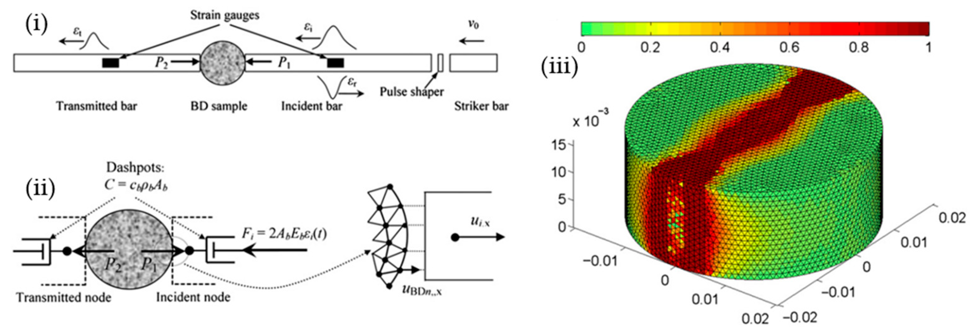
Nevertheless, the utilisation of FEM for simulating the process of rock fracture is accompanied by notable limitations [46,47] in spite of the improvements above. In the analysis of fracture growth and other phenomena characterised by significant deformations, it is necessary to frequently update the grid of FEM, leading to an augmented workload. In 1999, a novel approach known as the extended-FEM (XFEM) was introduced as a solution to address the issue of discontinuity [48,49]. XFEM facilitates the classical FEM to model cracks within finite elements through incorporating discontinuous basis functions, eliminating the necessity of remeshing as crack propagates. The independent nature of the finite element mesh and crack in XFEM facilitates the analysis of discontinuities in cracked bodies, hence contributing to its extensive use [50,51,52]. For example, Zhuang et al. [53] employed XFEM to conduct a comparative analysis of the fracture characteristics shown by unfilled and filled pre-existing faults, which revealed notable distinctions in terms of the stress required for crack initiation and the angle at which cracks formed between these two categories of flaws. Xie et al. [54] examined the initiation and propagation of fractures in rock-like material with closed fissures using XFEM. Moreover, the particle finite element method (PFEM) is another development of FEM for modelling rock fracture, which is particularly a very effective and reliable numerical technique for simulating rock fracture problems involving multi-physics in environments that are constantly changing. PFEM utilises the Lagrangian framework to autonomously detect and track interfaces between distinct materials, such as fluid–fluid, fluid–solid, or free surfaces, while utilises the conventional FEM to solve the governing equations and effectively addresses mesh distortion problems through a rapid reliable remeshing technique [55,56]. Nevertheless, some of these recent developments such as XFEM and PFEM have not been applied to simulate rock dynamic fracture and rock blast yet although they may be applied in investigating the dynamic behaviour of rocks such as evaluating the dynamic fracture toughness of rocks [57,58], which, thus, are not reviewed in the following sections. The first comprehensive finite element analysis of the dynamic fracture of rock-like materials under impact loads was probably conducted using a simple hypoelastic model in ADINA2D by Hughes et al. [59], who investigated the effects of varying the uniaxial tensile strength of the concrete on the crack initiation time, stress state, crack growth characteristics, and failure mode in the concrete specimen in the SHPB. Later, Zhu and Tang [60] implemented a strain-rate-dependent elastic damage model into 2D implicit FEM to study the deformation and failure process of a Brazilian disc of heterogeneous rock subjected to dynamic loading conditions. Zhou and Hao [61] employed a continuum damage model of AUTODYN2D explicit FEM to simulate the dynamic fracture behaviour of a three-phase concrete composite consisting of coarse aggregate, mortar matrix and interfacial transition zone. However, in both modelling approaches above, the SHPB is not simulated, probably due to intensive computation, and instead a simple waveform is applied to the Brazilian discs. Saksala et al. [62] conducted a series of 2D simulations of the dynamic fracture of rocks in the dynamic Brazilian disc (BD) tests with the presence of SHPB using FEM with a viscoplasticity- and damage mechanics—based constitutive model, which is supplemented by several genuine 3D simulations in order to verify the plane stress assumptions. Figure 2(i) shows a schematic SHPB configuration with BD specimen. The bars are represented by nodes, as depicted in Figure 2(ii). To achieve this simplification, it is necessary to connect viscous dashpots to the nodes in order to mimic the behaviour of long bars. The incident pulse is exerted on the incident node by multiplying it with the cross-sectional area and the Young’s modulus of the bars. The 3D damage localisation zone shows increased smoothness in the 3D scenario. Furthermore, there are no notable changes in the thickness of the disc in the area where damage has occurred, as shown in Figure 2(iii). The maximum tensile stress in the three-dimensional (3D) scenario exhibits a reasonably strong correlation with both the two-dimensional (2D) equivalent and the experimental outcome, as observed in Figure 2(iii).
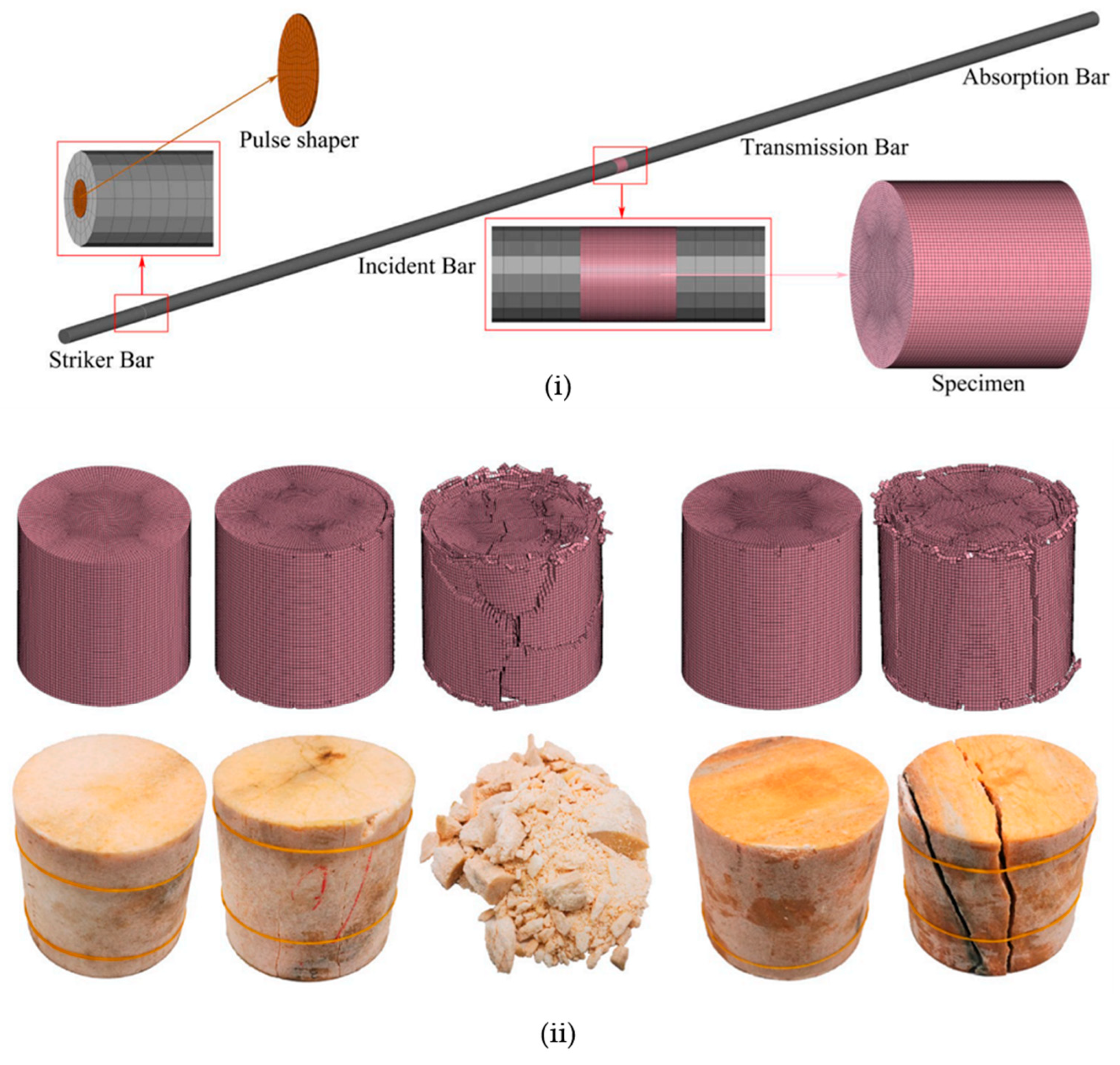
More recently, Wang et al. [63] established a numerical model of the dynamic uniaxial compression tests of marble in the SHPB apparatus using the FEM programme LS-DYNA to mimic the effects of repetitive impact loads for the first time. The Holmquist-Johnson-Cook (HJC) material model is implemented to simulate the dynamic fracture of marble under high strain-rate loads. The numerical model is constructed based on the experimental SHPB test system and consists of six components, as seen in Figure 3(i). The pulse shaper in the numerical model is positioned before the incidence bar, which matches the dimensions used in the experimental test. Figure 3(ii) illustrates the progression of failure modes in the marble when subjected to several impacts at velocities of 9 m/s and 10 m/s. The failure patterns between the simulated and experimental findings exhibit a high degree of agreement [63].

3.2. Modelling Dynamic Fracture in Rock Blasting Using Finite Element Method

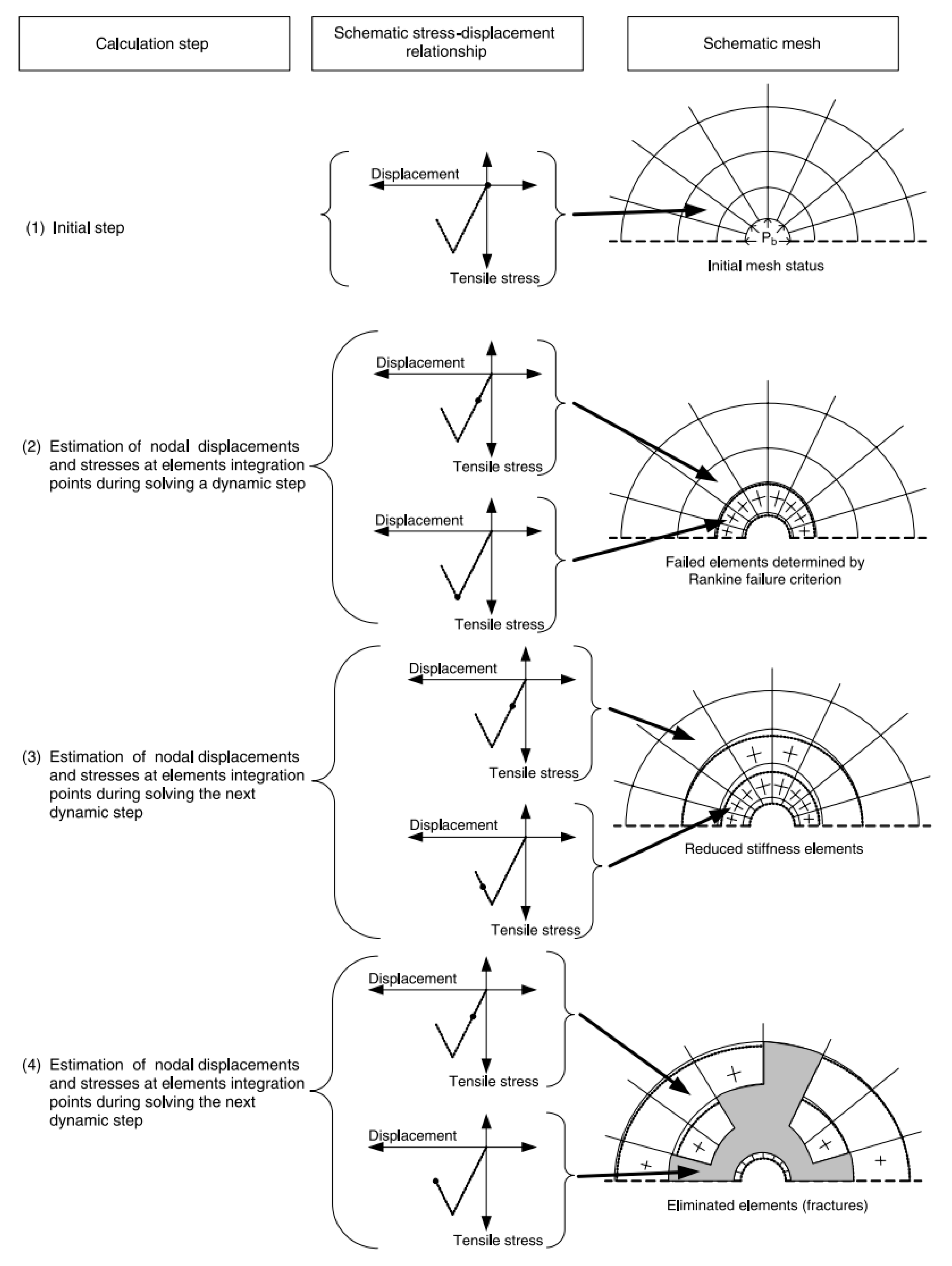
Besides being applied to model the dynamic fracture of rocks in dynamic experiments, FEM is applied to model rock fracture by blast at almost the same time or even earlier. FEM was initially implemented by Thorne et al. [64] to model fracture based on the constitutive damage theory, which was characterised by the gradual deterioration of material properties over time. A FEM was proposed by Cho and Kaneko [65] to model the detonation-induced dynamic fracture while neglecting the dynamics of the explosive gas. Explosion-induced fracture propagation was studied by Liu et al. [66] using a FEM with a gas expansion model, which took into account that the explosive gas entered the created fractures and caused them to expand, resulting in long radial cracks. A phenomenal constitutive model was implemented by Rouabhi et al. [67] into a FEM to model blasting-induced dynamic behavior of rocks, although they were unable to explicitly model any cracks or fragments. Rock blasting in mining sublevel caving was simulated using the explicit FEM LS-DYNA by Liu et al. [68], who compared the highly stressed regions with the phenomena observed in drifts after field blasting. Subsequently, a number of researchers [69,70,71,72,73] performed rock blast modelling using LS-DYNA with advanced material frameworks and under different loading and boundary conditions. The objective of these simulations was to accurately replicate processes such as the propagation of stress waves, the creation of crushed and cracked areas, and the initiation and expansion of long radial fractures caused by rock blasting. The rock fracture process was illustrated using the commonly established erosion approach, in which, once a predetermined erosion threshold of a material had been exceeded, the material was instantly eliminated from the system to effectively address the issue of excessive element deformation. Figure 4 presents a comprehensive depiction of the sequential procedures employed in the element elimination technique by Saharan and Mitri [74] to model the dynamic fracture of rocks by blast using ABAQUS with a material damage model. The rock material selected was granite, which has undergone thorough testing, and its qualities are well established and understood. The crack detection method relies solely on Mode I fracture analysis using the Rankine failure criterion. However, the subsequent cracking behaviour involves both Mode I (tension softening) and Mode II (shear softening = retention) physical activity. Once a certain level of fracture opening displacement is reached, the cracked element is eliminated from the calculations because it becomes unable to withstand any further loads. In order to remove an element, all the stress tensor’s components within that element are reset to zero. Consequently, all forces within this element are reduced to zero, causing it to no longer transfer any load to adjacent non-eliminated elements. To mitigate numerical issues arising from significant local loss of equilibrium, the stress is intentionally set to zero over multiple relaxation iterations. A deleted element refers to a significant break or fracture in the current state of development.
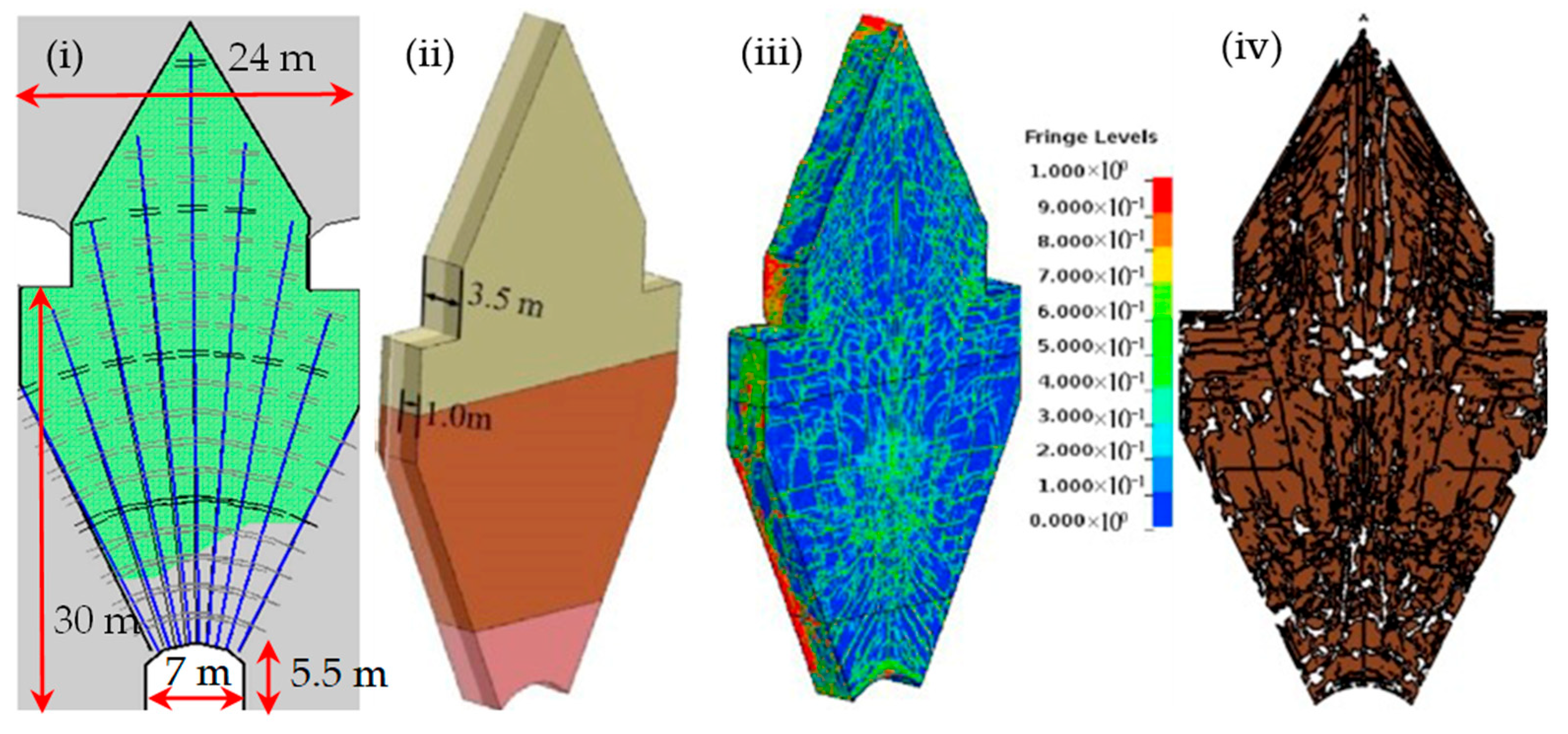
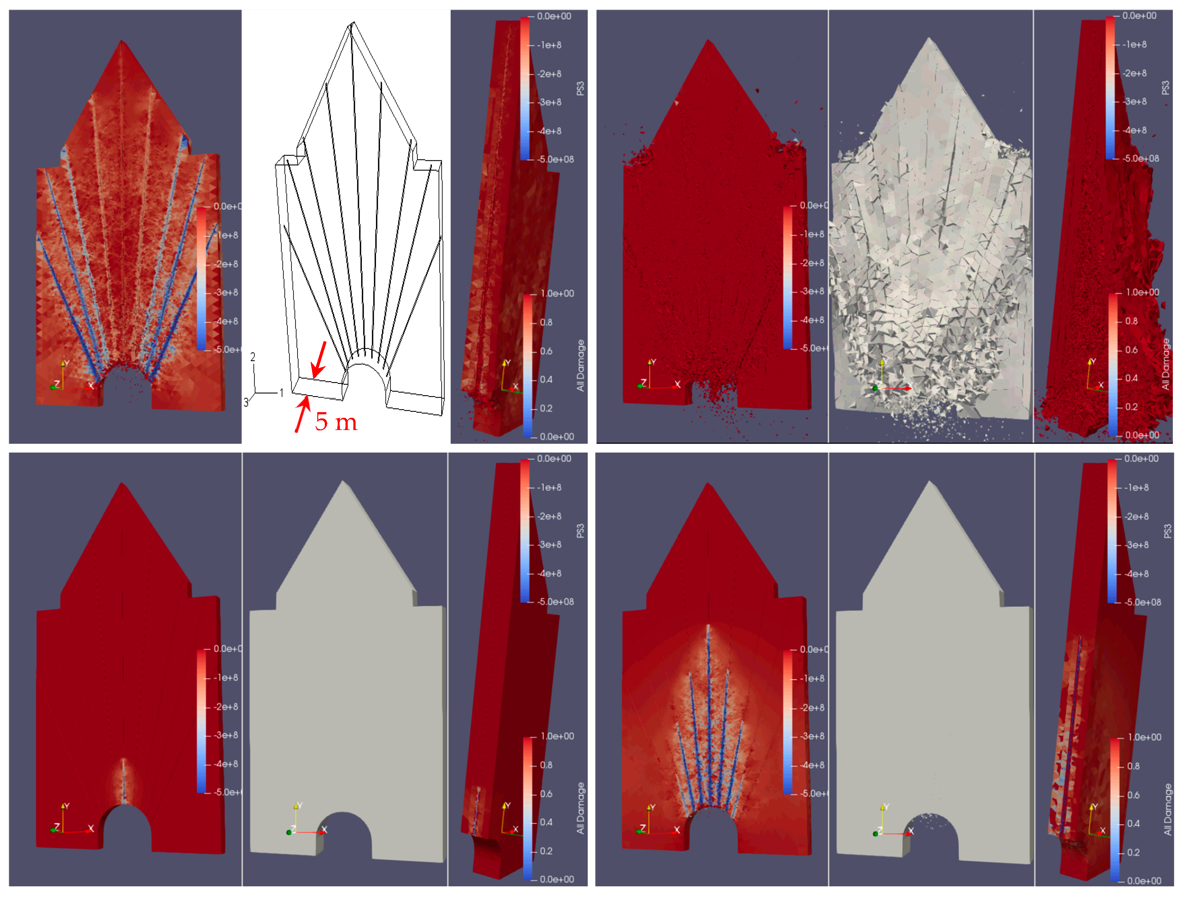
However, the timing of deleting the element is rather arbitrary. For example, Wang et al. [69] conducted an analysis of rock fracture by blast with LS-DYNA using critical tensile damage variable as an erosion criterion. Once the damage variable exceeded 0.6, the relevant component was immediately discarded as unsafe. Due to the inflexible nature of the elimination process, the removed material will not be able to resist the reversal of the applied force. Assuming there was no significant reverse loading, this method might be used to record the physical process of fracture. As a result of its widespread application in a variety of studies, the explicit dynamic FEM implemented in LS-DYNA, AUTODYN, ANSYS, and ABAQUS has become the gold standard for numerically simulating rock blasting. The primary reason for this is its effective management of short-term steps and utilisation of an explicit integration scheme, whose short time steps ensure numerical precision, making it ideal for simulating rock blasting. This phenomenon can be attributed to the relatively short duration of rock detonation events, which often span only milliseconds. Due to the explicit time integration technique, the factorization of the stiffness matrix during the iterative solution is unnecessary. Because of this, the solution can be implemented at the element level with only a small amount of high-speed storage needed. As a result, the calculation efficiency is much enhanced, which reduces the amount of time spent on calculations. In their study, Liu et al. [68] implemented the ABAQUS software combined with an element erosion algorithm and a damage model to simulate a range of rock blasting scenarios, which included simultaneous blasting and sequential blasting with varying delay intervals, as well as blasting in an isolated borehole within an infinite rock mass and blasting in a rock mass bounded with one reflective surface. Cracks in rocks generated by crater blasting were modelled using AUTODYN with the element erosion method [75], which observed that the material statuses undergo alterations as the explosion progresses along the charge axis. A significant shear stress field forms in the vicinity of the borehole as a result of the elevated shear stress. The rock undergoes significant crushing in the regions where shear failure occurs. In addition to the areas where shear failure occurs, there are other zones where failure is driven by tensile stress. Thus, the research on crater blasting demonstrates that there exists an ideal depth at which the explosive charge should be placed. Similarly, there is an ideal depth of burial for the explosive charge when using bench blasting [76], which concludes that, for the specific bench blasting model and materials (diorite and TNT), it is advisable to place the explosive charge at a significant depth, with the charge bottom positioned slightly higher (5%) than the bench bottom [76]. Decoupled charge blasting’s effect on rock fragmentation efficiency was investigated [77] using the AUTODYN software. The maximum intensity of the impact wave is reduced, the effect of the blast is prolonged, and the loading strain rate is retarded when using decoupled charge blasting, evidenced by numerical simulation and laboratory measurements. The LS-DYNA code was used to quantitatively investigate the fragmentation caused by a blast in sublevel caving. The numerical simulation was based on the blasting design of the LKAB Malmberget mine [78], as shown in Figure 5(i) The explosion was simulated using an explosive material model in LSDYNA, incorporating the JWL equation of state. The block depicted in Figure 5(ii) is selected as the object of evaluation [79]. Following the calculation, the distribution of damage inside this block is illustrated in Figure 5(iii). A damage level of 0.6 is the threshold at which the rock is deemed completely crushed. Subsequently, the elements exhibiting a damage level over 0.6 were intentionally obscured, resulting in the formation of fissures within the rock mass. While it is simple in 2D, it is difficult to recognize the fragments in 3D. The cross-section depicted in Figure 5(ii) is selected for the purpose of evaluating the area of the fragment within this cross-section. The crack pattern of this cross-section is depicted in Figure 5(iv). Subsequently, an algorithm was devised, and a procedure was executed to identify fragments delimited by fractures, which correspond to completely crushed parts, and ascertain the area of each individual fragment. Besides, Bird et al. [80] presented a non-linear 3D finite element model to simulate blast-induced wave propagation, which was supplemented by a post-processing algorithm to calculate the fracture intensity. Zhang et al. [81] implemented LS-DYNA to model the explosion under biaxial and triaxial confining pressures, investigating the effects of confining pressure on the damage characteristics of the rock mass.
However, although the explicit dynamic FEM implemented in LS-DYNA, AUTODYN, ANSYS and ABAQUS is able to simulate the blast-induced wave propagation in rocks through damage and erosion algorithms, there are some challenges in modelling the expansion and flow of explosive-generated gas through propagating fractures connected to boreholes during the gas pressurisation loading phase of rock blast, which is either ignored or modelled through coupling with complex and extremely computationally intensive computational fluid dynamics software.

3.3. Modelling Dynamic Fracture in Dynamic Tests Using Discrete Element Method

Since the 1980s, discrete element modelling (DEM) has gained prominence as a reliable technique for analysing rock and granular materials subjected to static and dynamic loads. In this section, the development of DEM for modelling rock fracture is first presented, which is followed by the application of DEM to model dynamic rock fracture. In DEMs, rock and granular materials are often represented by a network of interconnected particles such as circles in 2D or spheres in 3D [82]. To solve the mathematical models of the interaction among these particles, the DEM often adopts an explicit time-domain integration, in which a bonded-particle model (BPM) has been proposed for the purpose of evaluating the fracturing behaviour of rocks. In BPM, a numerical model is built to represent rock as a compact arrangement of circular or spherical particles of varying sizes, and these particles are bonded together at their points of contact, such as those in PFC2D and PFC3D, which are the most popular DEMs commercialized by Itasca [83,84]. Potyondy [85] detailed the micromechanical mechanisms of BPM that regulate stress-induced brittle fracturing in porous or compact rocks with varying degrees of pre-existing damage. To ensure accurate rock behaviour in simulations, all DEM-based approaches require a calibration process to define acceptable micro-property inputs. This involves a trial-and-error approach, where the DEM model is adjusted against global measurements until the outputs match experimental observations. However, this time-consuming process does not enhance the understanding of the physical parameters behind the model, raising computational reliability concerns [86,87]. The particle-level contact hypothesis is the primary driver of the modelled macroscopic behaviour of rocks. The contact bond model (CBM), the parallel bond model (PBM) [82], and the flat-joint model (FJM) [85] are among the most well-known contact models. The CBM and the PBM are fundamentally distinct in that the former’s contact interface is incapable of resisting relative rotation and can only transmit force, whereas the latter can resist relative rotation and transmit both force and moment. The PBM more effectively replicates finite-sized portions of materials between two contact particles [88]. Potyondy [89] introduced the FJM as a new bonding-material model that simulates the mechanical behaviour at the interface of two notional surfaces. It resolves three challenges that are present in PBM and CBM by offering four significant enhancements: (1) The interface is modelled with multiple elements that can be bonded or unbonded in order to depict authentic particle rotation and interlocking in FJM. (2) In contrast to PBM, which experiences a loss of rotational resistance upon fracture, FJM continues to resist rotation. (3) The tensile strength of both PBM and FJM is pressure-dependent. (4) Through various flat-joint contact patterns, FJM is capable of simulating pre-existing fractures and exposed pore spaces [90].
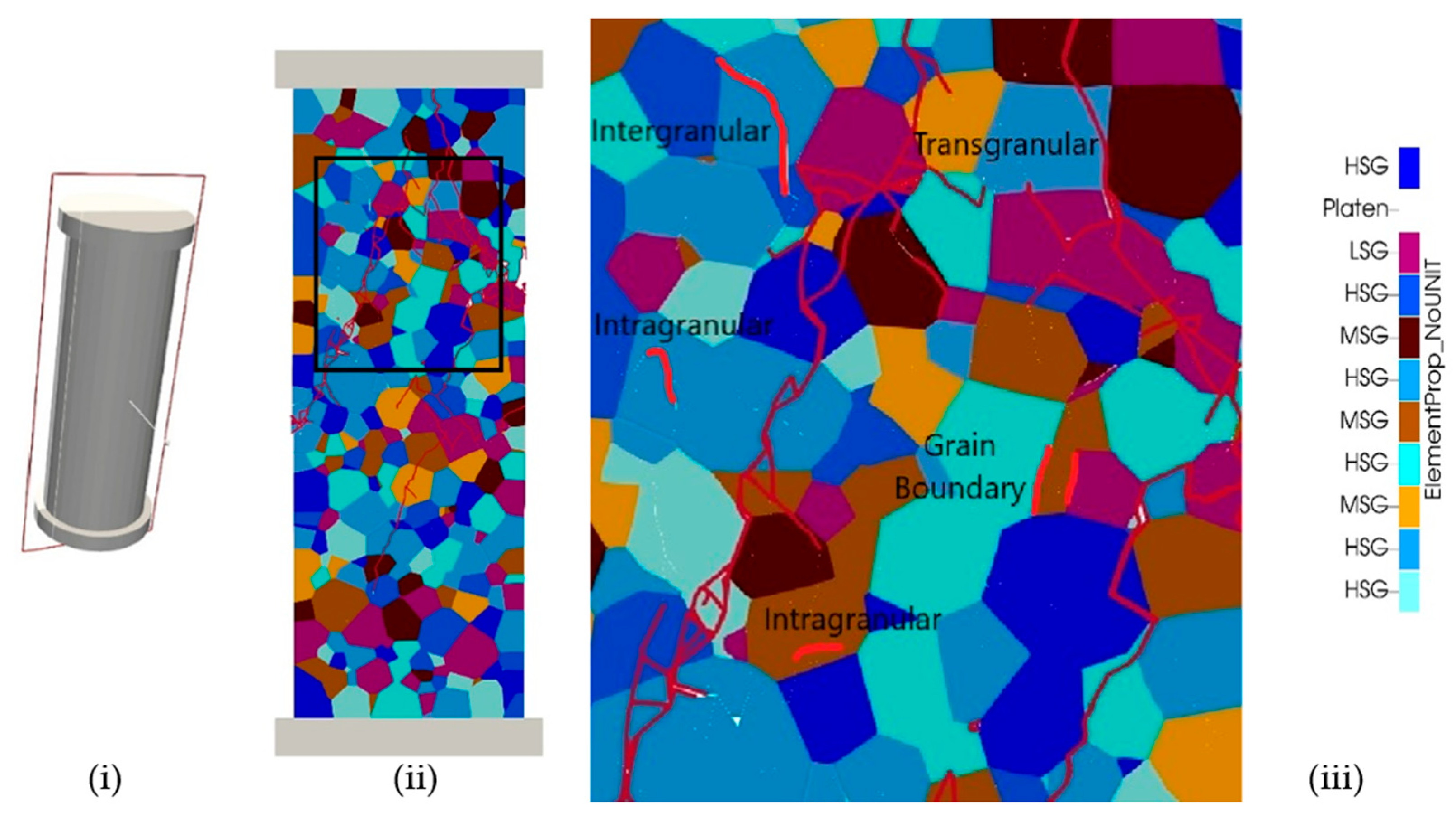
The dynamic response of rocks is increasingly modeled using DEM in the context of split Hopkinson pressure bar (SHPB) testing systems. This approach captures intricate fracture mechanisms and stress wave propagation at the microscopic scale. A detailed analysis of the mechanical properties of granite rock specimens under different hydrostatic confinements during SHPB is analyzed by Li et al. [91] using the DEM2D. The 2D numerical model findings demonstrate the dynamic strength of rock specimens escalates with increasing strain rates; however, their sensitivity to the strain rates decreases with more hydrostatic confinement. Moreover, at a specific strain rate, increased hydrostatic confinement results in the generation of a greater number of intact rock fragments and a wider variety of fragment sizes. A numerical triaxial Hopkinson bar system is established using a three-dimensional (3D) coupled continuum–discrete technique by combining FLAC3D with PFC3D [92], as shown in Figure 6(i). The steel bars are modeled using continuum zones of FLAC3D, while the cubic specimen is modeled using bonded-particle material of PFC3D, as depicted in Figure 6(ii). Throughout the numerical modelling, it is found that, in general, the failure modes of rock under multiaxial loads are influenced by confinement and show a clear dependency on it. Uniaxial compression causes substantial damage to sandstone, resulting in the fragmentation of tiny pieces and the formation of fine powders (Figure 6(iii)). The utilization of X-ray CT method allows for good visualization of internal fractures following an impact. The failure mechanism becomes more evident under biaxial compression, as seen in Figure 6(iv). Multiple prominent cracks are found connecting the corners to the center and intersecting with one another. Consequently, sandstone is partitioned by fracture planes into two roughly symmetrical V-shaped regions of damage at the upper and lower sections, with a comparatively undamaged concave block in the middle. Applying lateral confinements during the triaxial compression test greatly reduces the extent of damage. Only a few noticeable cracks can be seen at the edges and surface (Figure 6(v)) [92]. Furthermore, an open-source program called YADE was developed by Kozicki and Donzé [93] using concepts that were comparable to PFC, which was originally proposed by Frédéric and Magnier [94] and Donzé and Magnier [95]. The use of an interaction detection coefficient and a softening factor in YADE enhances its capabilities in controlling the released energy and nonlinear failure compared to PFC formulation [36]. UDEC or 3DEC is another viable DEM alternative to PFC for modelling rock fracture mechanisms, but the particles in UDEC and 3DEC can be any general sizes and shapes. The Voronoi joint generator is discovered to be highly advantageous for the numerical simulation of the formation and propagation of rock cracks as a result of fracturing. The three-dimensional Northern Perth Basin borehole drilling process was replicated by 3DEC. The magnitude of the yield zone surrounding the borehole is calculated and compared with caliper log measurements to determine the borehole deformation. It was determined that the strength of the rock is a crucial determinant in regulating the stability. The results indicate that an increase in viscosity correlates with an increase in fracture shearing and consequently leads to instability surrounding the borehole [96]. However, it is not without its limitations. The primary limitations encompass the reliance on particle size in both simulation and calibration stages, the tendency to overestimate tensile strength, the dependence on a linear failure envelope, the consideration of a low friction angle, and the challenges associated with modelling intricate geometries. Given that the parameters previously mentioned are utilised to assess both normal and shear bonds, the calibration and execution of the model would be exceedingly time-consuming, particularly for extensive fracture process simulations [97].

3.4. Modelling Dynamic Fracture in Rock Blasting Using the Discrete Element Method

Preece [98] was the pioneer in applying the DEM to the rock blasting process by simulating the movement of circular particles ejected from the blast site by the explosive gases. Nevertheless, Preece [98] did not incorporate a model for the fragmentation of rocks. This is due to the assumption made in the calculations that the rock had already been fractured before conducting the analysis. In contrast, Song and Kim [99] proposed a DEM that utilized Newton’s second law of motion to investigate the rock fracturing phenomenon resulting from rock blasting. The model incorporated point masses or particles to represent the rock, with interconnections established by massless springs. Additionally, it incorporated the inhomogeneities inherent in geological materials, such as rock. The findings demonstrated that the DEM has the ability to simulate a range of dynamic fracture characteristics, such as crack branching and wave propagation.
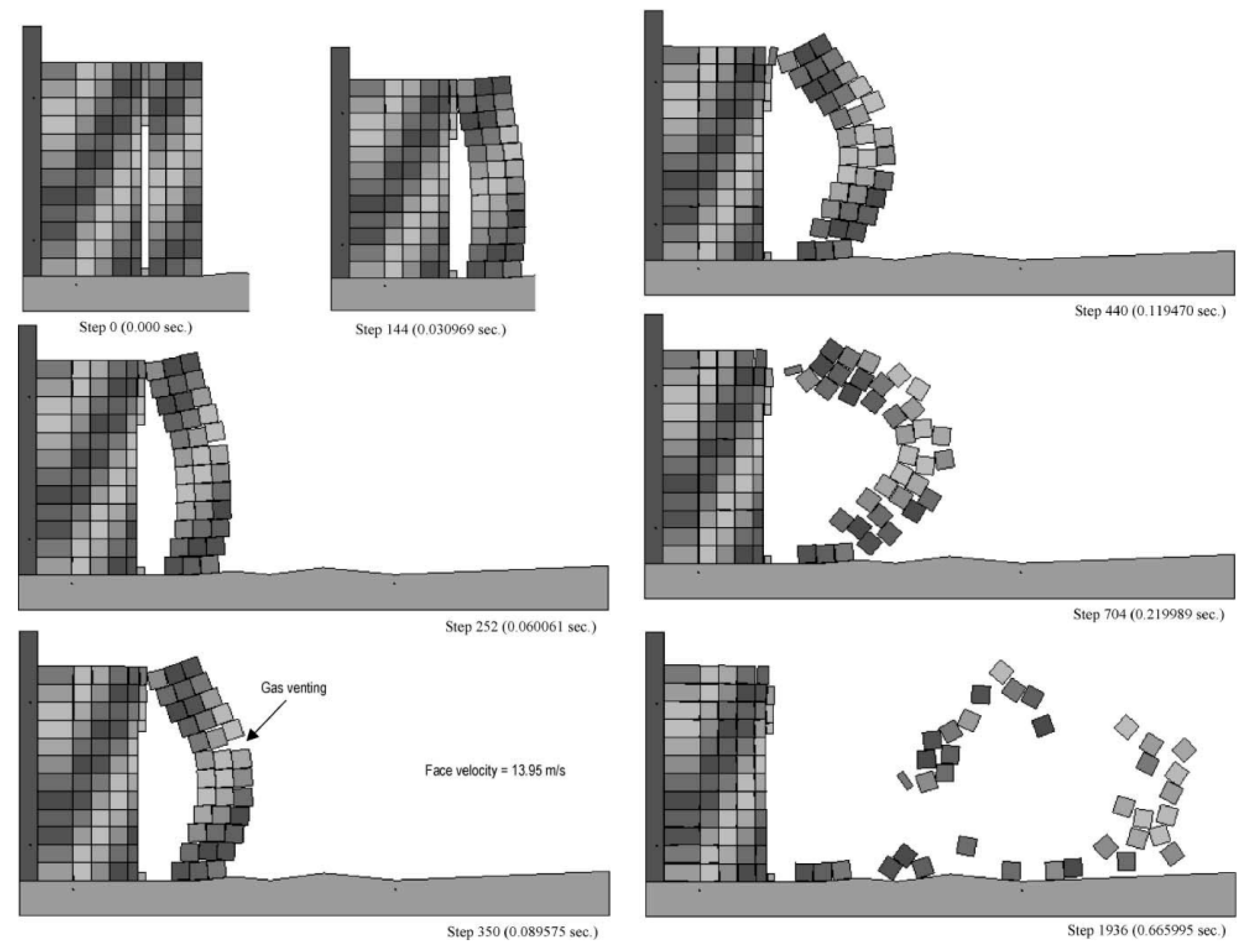
Potyondy et al. [100] integrated a PBM into PFC2D (DEM2D), similar to the approach of Song and Kim [99], in order to simulate the initiation and propagation of cracks generated by blasting. The incorporation of bonds between discrete particles was carried out in the PBM to enhance the material’s strength capabilities. These bonds help to keep the particles in close proximity and sustain their geometric configuration by enhancing the structural integrity of diverse geological formations. The potential failure of these bonds may occur as a result of the application of tension, shear, or compression stress that exceeds the strength capacity of the material. Donze et al. [101] developed a DEM to investigate the fracturing process that occurs when a cohesive elastic–brittle material is subjected to stress wave loading. This method considers the initiation and propagation of discontinuities around the blasting hole during rock blasting. A discrete element model for expanding the blasting chamber has been introduced by Mortazavi and Katsabanis [102] based on discontinuum deformation analysis (DDA), utilizing the dynamic monitoring of rock blocks located in the vicinity of the blasthole. All input parameters were kept constant during the model execution, except the burden size. The outcomes of the DDA_BLAST simulation for different burden distances are illustrated in Figure 7. Due to the limited number of blocks involved and the complete control of block interactions by the gas force, the behaviour of the granite mass exhibited less nonlinearity compared to the scenarios involving greater loads. Significant deformation resulted in the burden opening at its midpoint (Figure 7, steps 252–440) [102].
Zhao et al. [103] investigated the phenomenon of stress wave propagation and attenuation in jointed rock masses using UDEC software. However, it is important to note that their study did not incorporate any modelling of damage or fracture. Saiang [104] employed an integrated continuous–discontinuous model by utilizing PFC2D and FLAC software to replicate the damage zone caused by blast-induced effects in deep underground areas. The method combined FLAC for the exterior segment and PFC2D for the interior segment. At 15-item intervals, blast-induced radial fractures were individually incorporated in the PFC2D component of the coupled model. The failed zones in the coupled model were compared. Failed regions are those in which particle contacts have been severed but no actual dispersion has occurred. The forces were monitored so that the mechanisms causing the failure could be observed. These mechanisms operated under compression or tension. However, Saiang [104] incorporated artificial radial cracks caused by blasting into the continuum–discontinuum model as separate entities, rather than being generated by the rock blasting. Ning et al. [105,106] utilised the well-known DEM method, specifically the distinct deformation analysis (DDA), to model the failures of rock masses caused by the high-pressure expansion induced by blasting. This involved applying the instantaneous gas pressure generated by the explosion against the walls of the primary blast chamber and the artificially created interconnected fracture surfaces surrounding it. The objective of the DDA simulation was to mimic the formation of the explosion pile and the subsequent rock mass casting process. However, the model did not account for the initiation and growth of lengthy cracks, stress waves, and the crushed and fractured zones. To simulate the entire process, from the initial detonation of the detonation material to the subsequent rock breaking and fragmentation, a Hybrid Stress Blasting Model (HSBM) was presented by Onederra et al. [107]. The HSBM algorithm employed a combination of continuum and discontinuum methods to model blast wave propagation in rock. An assortment of accelerometers, geophones, and strain gauge sensors were used for measuring the block. The purpose of the instrumentation setup was to investigate the relationship between the ultimate degree of damage and the forces caused by blasting. After 20 ms, the modeling results are portrayed in Figure 8. The volume of the burden was fractured and ejected. The illustration shows interior damage in red and major fractures in black. The representations demonstrate the intricate configuration of the damage zone in relation to the impact of the boundary conditions and point of initiation. The plan view section illustrates that the damage extension is larger in the vicinity of the hole collar compared to the explosive charge’s toe (place of initiation). The HSBM code was able to approximate the dispersion of fragments and include the impact of stress waves and gas flow in the calculations, but it failed to accurately account for stress wave propagation, the development of crushed and cracked zones, or the pattern of fragment distribution, which were mostly scattered independently.
Fakhimi and Lanari [108] developed a hybrid method for describing rock blasting that combines DEM with SPH. To replicate the rock’s behaviour, the DEM was utilized with a BPM, and SPH was used to demonstrate the flow of gases. The model effectively represented the evolution of rock fracture, with a focus on the crushed region, axial fractures, and surface spalling. Lak et al. [109] applied DEM to model the propagation of blast-induced fractures in rock, accounting for both pre-existing fractures and newly generated cracks within the rock mass. The discrete fracture network (DFN) approach is used to generate cracks within the rock mass. By employing the Voronoi tessellation method to subdivide the entire rock blocks into secondary blocks, the possibility of fracture propagation is improved. The simulation results reveal the mechanisms that cause fractures to grow in both the circumferential and transverse directions of a borehole. The pre-splitting at the back of the blast hole is modelled and analysed to determine how it affects the process of crack propagation within the blasting area. The adopted modeling approach successfully simulates explosion processes, as well as various mechanisms of fracture propagation and fragmentation within rock masses [109]. The high in situ tension of the deep rock mass and the limiting influence of the surrounding rock during shallow hole blasting lead to low borehole exploitation and insufficient blasting impact. Deep hole multi-stage cut blasting presents an efficient method for excavating vertical shafts. To better understand blasting cavity features, fractal damage, and rock fragmentation, a continuum-based DEM is applied by Ding et al. [110] to the analysis of deep hole multi-stage cut blasting of a vertical shaft. The results show that inadequate cavity across the cut axis occurs when the initial stage of multiple-phase cut blasting in a vertical shaft has an inappropriate or excessive length percentage. As the size of the first stage increases, the sequence of development and reduction reveals distinctive parameters, including the spiral destruction of the blasting opening, the extent of cracking in the component, and the crack degree at the interface. Moreover, the length of the initial phase relative to the overall length has an optimal value [110].
Nonetheless, while DEMs including PFC2D/3D, UDEC and 3DEC excel at depicting the dynamics of rock fragments, they encounter many challenges such as modelling intact rock behaviour, the transition from continuum to discontinuum, as well as deformable and breakable rock fragments, which face the issues of parameter calibration and intensive computation.

3.5. Modelling Dynamic Fracture Using the Combined Finite–Discrete Element Method

The reviews on modelling rock dynamic fractures using DEM in Section 3.4 and Section 3.5, as well as comprehensive reviews on numerical methods for modelling rock failure [2,35], suggest investigating the dynamic fracture of brittle materials using a hybrid continuous–discontinuous method, which combines/couples the advantages of continuum-based and discontinuum-based methods while surpassing their respective disadvantages. We particularly focus on the combined finite–discrete element method (FDEM), originally proposed by Munjiza [111], which has garnered considerable interest in recent decades [112,113,114,115]. This is due to the fact that it combines the benefits of continuous and discontinuous methods and can simulate the fracturing-induced transition from a continuum to a discontinuum. This section first gives an overview of recent developments of FDEM for modelling rock fracture and then typical results of modelling dynamic tests such as dynamic SHPB-based BTS and UCS tests without reviewing its application in rock blasting, which is to be introduced in the next section.

3.5.1. Review of the Development of the Combined Finite–Discrete Element Method

FDEM was originally proposed by Munjiza [111], who released the first open-source FDEM code, i.e., Y-code. The Y-code has now been further developed and extended by many researchers to be broadly applied in geotechnical applications. The Y-code has a comparable characteristic to DEM, namely BPM, in which solid bodies are substituted by deformable components. However, the Y-code conceptualizes any structure as a collection of discrete objects in motion that interact. These components are then reduced to finite elements in order to model deformability, failure and fragmentation, even in the case of intricate geometries. The initial code utilised an infinite strain triangle structure to model two-dimensional challenges, including those that were both linear and nonlinear. The integrated model incorporates ICZM to replicate strain-hardening behaviour, comparable to the techniques incorporated into the standard FEM. Alternatively, fracture mechanics (the amount of energy collapse threshold) and damage mechanics concepts are applied to the strain-softening portion. Fracture growth and initiation are facilitated through the process of combined finite element separation. These elements are held together by a specified bonding stress, which is determined by the damage index and peak tensile and shear strengths. The ELFEN code is another combined FDEM code that was initially developed for the purpose of simulating the behaviour of brittle materials when subjected to impact loading. The transition from continuous to discontinuous through the use of discrete fracture insertion describes the fundamental concept that drives ELFEN. According to Klerck et al. [116], the medium-dimensional structure in ELFEN can be explained by employing an explicit FEM. By establishing a modified Mohr–Coulomb elastoplastic paradigm that is capable of dealing with both tension and compression states, it is possible to obtain continuum-based failure and fracture processes that are connected with the softening of the material. It is also possible to obtain strain localization by taking into consideration the principles of fracture mechanics. The Rankine rotating crack model is incorporated into the code so that tensile fractures can be modelled accordingly. In addition, in order to cope with a coupled compressive and tensile stress field, a so-called compressive fracture model is utilized. This model is composed of the Rankine rotating crack model and the isotropic non-associative Mohr–Coulomb yield surface. Through the process of translating the virtual smeared crack into a physical fracture in the mesh, a nodal fracture strategy is accountable for the shift from continuum to discontinuum. The plan consists of three stages: (1) the development of a failure track for the entire domain, which defines a failure factor as the ratio of the inelastic to critical fracturing strains; (2) the determination of the trajectory of fractures in relation to the magnitude of the failure measure; and (3) the insertion of discrete fractures and the remeshing of the cracks. When considering inter-element fracture insertion, where ill-posed conditions may arise, ELFEN is computationally intensive despite its relatively superior capability in simulating the post-failure behavior of rocks compared to continuous and discontinuous methods.
Subsequently, Xiang et al. [117] adopted a second-order tetrahedral element to expand the capabilities of Y-code to 3D obstacles. In order to further streamline the use of Y-code, Munjiza et al. [118] designed a virtual geoscience workbench. Y-Geo was later introduced by Mahabadi et al. [119], which was designed on the basis of the original Y-code and had certain characteristics improved so it could be deployed more effectively for rock engineering issues. In a software package called MUNROU, Rougier et al. [112] introduced yet another enhancement to Y-code. Liu et al. [113] developed an integrated development environment (IDE) of two-dimensional and three-dimensional hybrid finite–discrete element method (HFDEM2D/3D) on the basis of the Y library using Visual C++ and OpenGL, which not only simplifies the use of FDEM through graphically building numerical models and visually displaying calculated results in real time but also provides a platform for further developing FDEM. In order to simulate the behaviour of solid materials with the help of cutting-edge technology for entire fluid–solid interaction, researchers at Los Alamos National Laboratory (LANL) created the Hybrid Optimisation Software Suite (HOSS) [120], a hybrid multi-physics platform based on FDEM. Irazu, a commercial version of Y-Geo that included 3D capabilities, was later developed [121]. On the basis of FDEM, an improved integrated hydro-mechanical model (FDEM-flow) has been developed that accounts for both fracture seepage and flow through porous media by Yan et al. [122].
FDEM is computationally intensive, which promotes the application of parallel computation in FDEM. Lei et al. [123] utilised the MPI (Message Passing Interface) to propose a synthetic parallelism mechanism for the hybrid FDEM. This approach allows for scalability, enabling the system to handle a range of CPU core configurations, from a small number to a large-scale deployment including thousands of cores. The HOSS with MUNROU code was introduced by Rougier et al. [109] and employed 208 processors coordinated by MPI. The programme featured novel methods for contact detection and contact strength computation. The effective simulation of a dynamic Brazilian rock test employing a SHPB apparatus has been accomplished in three dimensions utilising the developed technology. ELFEN efficiently utilises MPI for its parallelization, enabling its application in both two-dimensional (2D) and three-dimensional (3D) simulations of rock fractures. Hamdi et al. [124] asserted that a conventional laboratory test for fracture process analysis using ELFEN can involve the utilisation of up to 3 million components in a three-dimensional context. Xiang et al. [125] made improvements to the contact detection technique in their Solidity code and implemented parallel execution using OpenMP, who successfully reproduced a configuration consisting of 288 boulders resembling rocks and noticed a significant acceleration of 9 times while employing 12 concurrent CPU processes. Guo and Zhao [126,127] made significant contributions to the field of MPI-based parallelization and developed a hierarchical FDEM coupling technique, which was subsequently employed in the analysis of granular rocks by Wu et al. [128,129]. In the majority of instances, achieving ideal performance using MPI typically necessitates the utilisation of a large-scale and economically expensive PC cluster. Nevertheless, the practical implementation of shared-memory programming techniques such as OpenMP is constrained by the number of multiprocessors present in a system. As a result, the utilisation of MPI remains indispensable for addressing intricate problems. Consequently, in systems where information needs to be shared among multiple processors, both OpenMP and MPI are employed. Therefore, the utilisation of a hybrid MPI/OpenMP approach is necessary.
Besides the parallelization schemes based on CPUs, General-Purpose Graphics Processing Units (GPGPU) provide an alternative method to parallelize FDEM codes using the Open Computing Language (OpenCL) [130] or the Compute Unified Device Architecture (CUDA) [131] C/C++. Nowadays, a GPGPU card of a portable laptop or a slightly more advanced desktop PC/workstation is equipped with tens or even hundreds and thousands of GPU-core processors for parallel visualization and computation. Moreover, the laptop or desktop PC/workstation with GPGPUs consumes much less energy than CPU-based clusters. A GPGPU-based FDEM commercial code, namely Irazu, was developed with OpenCL to model rock fracturing processes [115,132]. Fukuda et al. [133,134] first parallelized the hybrid finite–discrete element method Y-HFDEM IDE2D/3D initially proposed by Liu et al. [113] using GPGPU with CUDA C/C++. Detailed computing performance analysis shows the GPGPU-parallelized HFDEM can achieve maximum speed-ups of 128.6 [133] and 286 [134] times in the case of 2D and 3D modellings, respectively, at that time. Subsequently, many researchers adopt the GPGPU parallelization scheme with CUDA C/C++ to parallelize various FDEM codes. For example, to overcome the problem sensitive to the non-uniform size of TET4s, Liu et al. [135] introduced a new GPGPU-parallelized contact detection algorithm, which performed contact detection searches in consecutive two phases, i.e., neighbour search and fine search, but is insensitive to meshes. Lei et al. [136] further improved the mesh-insensitive contact detection search algorithm by only allocating GPU’s memory to the grids with at least one solid element while deleting any memory allocated to the grids without any solid elements, which reduces memory usage for some special applications with irregular modelling domains.

3.5.2. Review of Modelling Dynamic Fracture in Rock Dynamic Tests Using FDEM

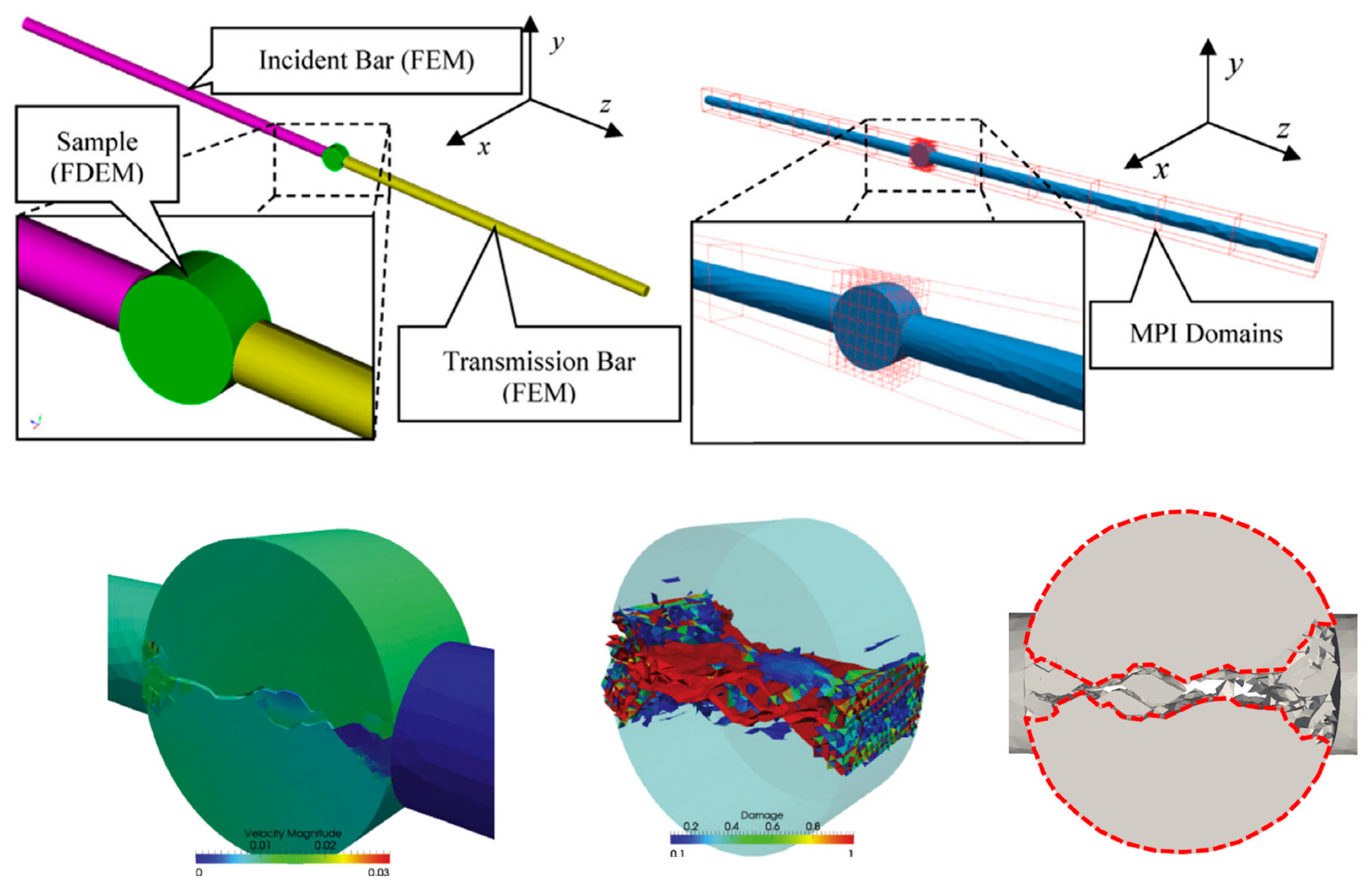
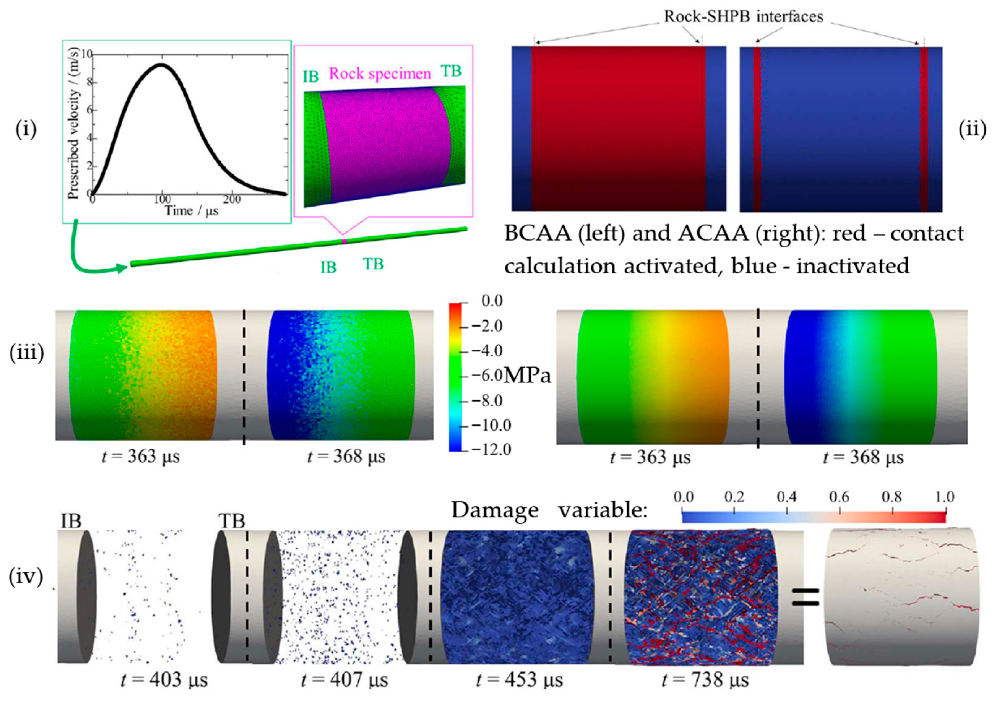
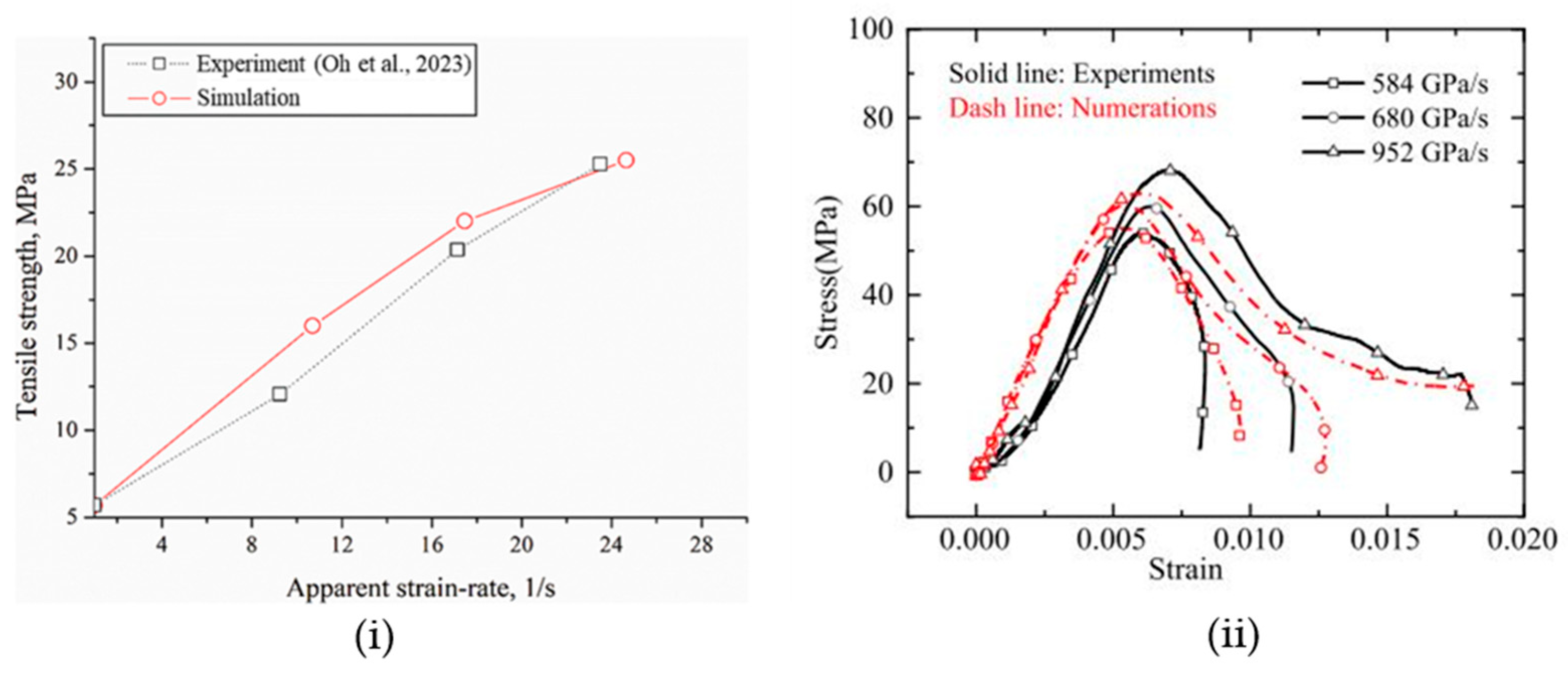
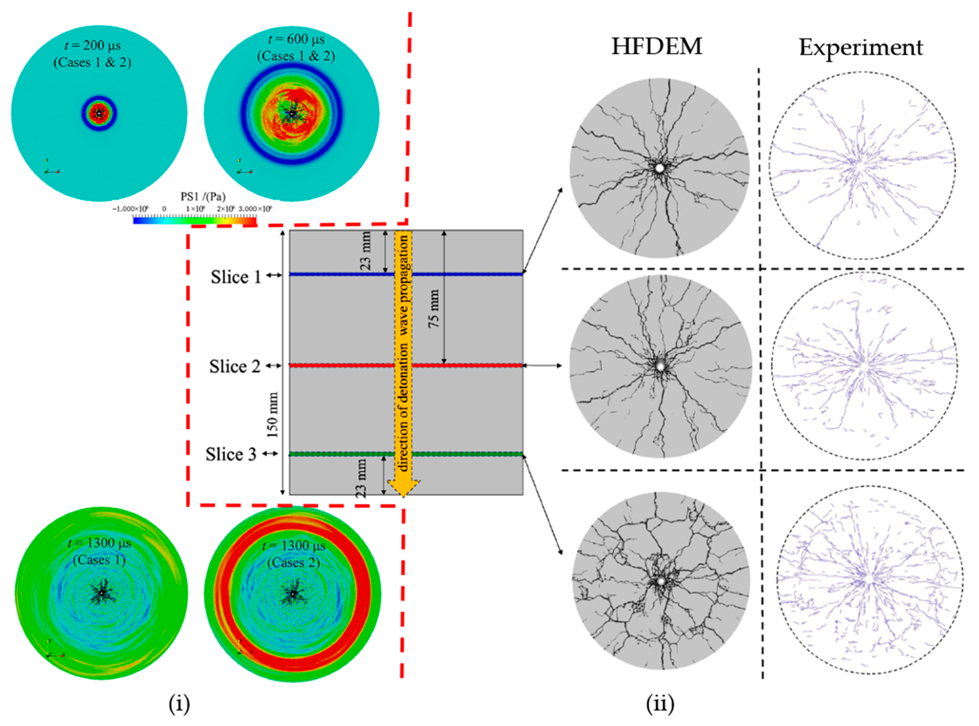
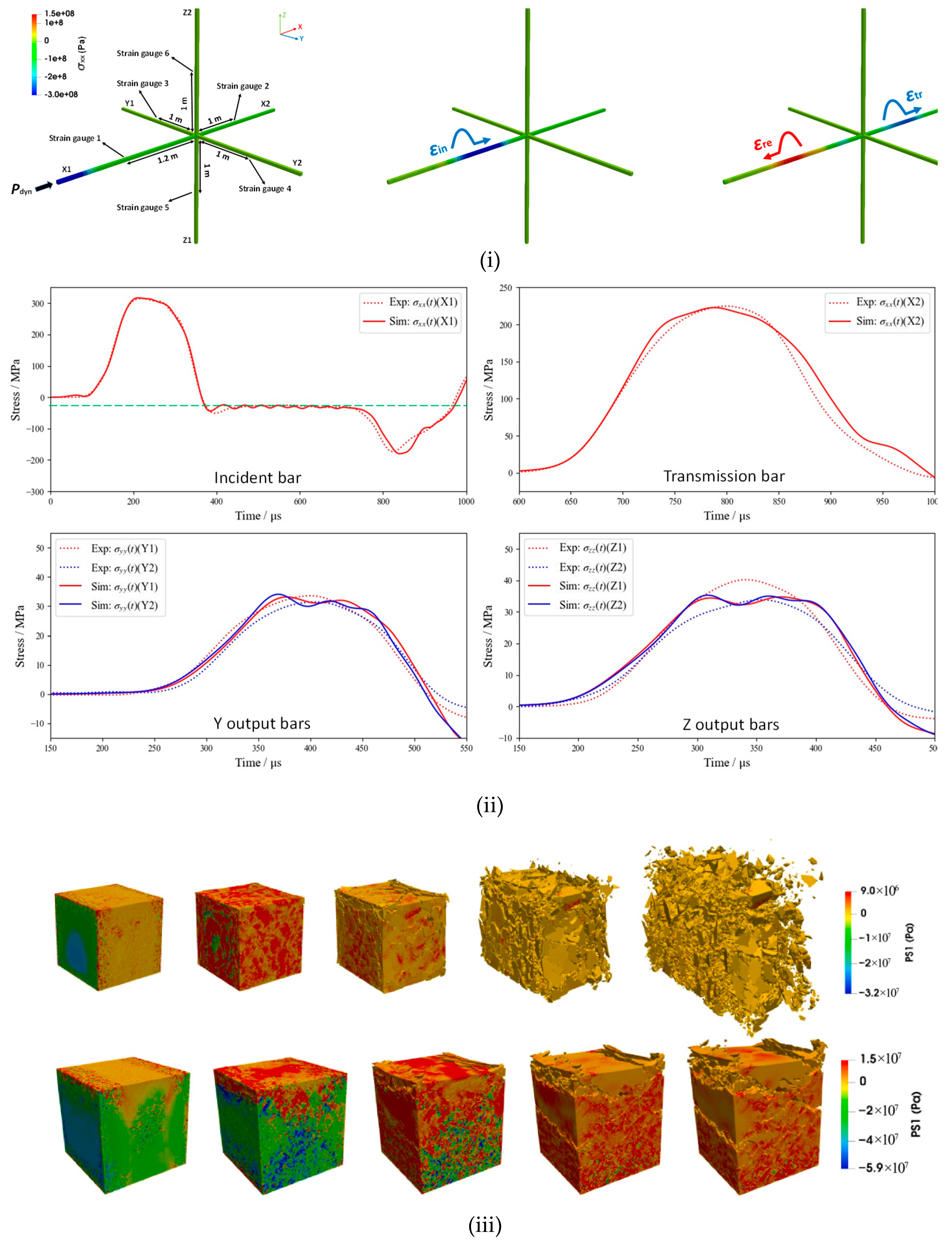
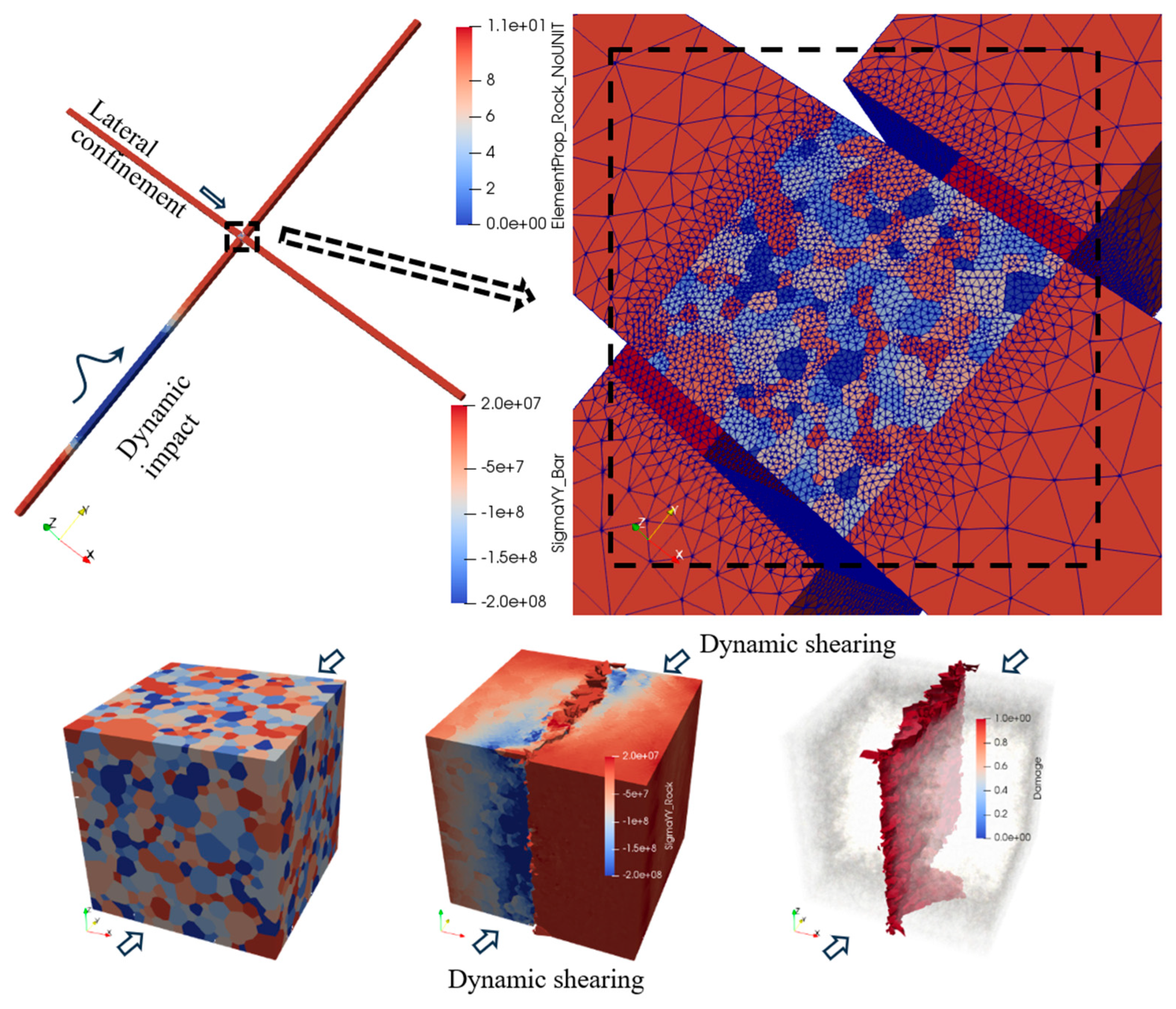
The application of FDEM in dynamic fracture modelling permits a comprehensive analysis of the behaviour of materials subjected to dynamic loading conditions. In a dynamic BTS test with a SHPB apparatus, Mahabadi et al. [137] used 2D FDEM to simulate the dynamic fracturing process of Barre granite. There was good agreement between the numerical simulations and experiments. The model also used a large, single-triangular element for each SHPB bar, which was given mechanical characteristics and had velocities specified to all of its nodes. The element employed for illustrating the SHPB bar could become rigid, rendering meaningless the mechanical characteristics provided (aside from contact friction and penalty). In addition, the present FDEM community generally acknowledges that distinguishing between mode I and mode II fracture energies is necessary for realistic rock fracturing computations; nevertheless, this is not the case. The dynamic BTS experiments of weathered granite were simulated by Rougier et al. [109] utilising 3D FDEM (HOSS) software, specifically taking into account elastically deformable SHPB bars. As can be seen in Figure 9, the sample was broken down entirely, with the two endpoints that touched the bars showing signs of linked cracking and fragmentation. The experimental and 3D-simulated final fracture patterns are displayed side by side. The experimental data are superimposed on top of the numerical experiment fracture pattern (red dotted line), demonstrating the remarkable precision of the fracture pattern acquired and used in the MUNROU algorithm. The combined results provide assurance in the correctness and robustness of the most recent 3D FDEM techniques and encourage additional research and improvement [138]. Moreover, Fukuda et al. [134,139] implemented GPGPU-parallelized HFDEM3D to investigate dynamic rock fracture in SHPB-based dynamic BTS and UCS tests, which yielded new perspectives and important discoveries of applying FDEM to model dynamic rock fracturing. An innovative semi-adaptive contact activation approach [139] is developed to significantly accelerate 3D FDEM modelling compared with the brute-force contact activation approach prevalent in the FDEM community. Figure 10 shows the numerical model of the SHPB-based dynamic UCS test, axial stress wave propagations during the intact rock deformation stage, special damage distribution of softening/broken thickness cohesive elements (CE6s), and failure pattern modelled using HFDEM with BCAA and semi-ACAA. Wu et al. [140] implemented finite-strain-based Mohr–Coulomb (MC) elasto-plastic continuum elements into the GPGPU-parallelized HFDEM to mimic the SHPB-based dynamic BTS and UCS experiments, which overcame the excessive fractures and inappropriate overestimations of local stresses and particle velocities in conventional FDEM simulations.
Besides modelling rock dynamic experiments, FDEM has been applied by some researchers [141,142,143,144,145,146]. Mohammadnejad et al. [141] modelled a series of rock cutting tests, which investigated the influences of cutting velocities, cutter rake angles and cutting depths on the rock chipping process. It was the first time that a few cycles of cutter/rock interactions were simulated. It is concluded that the mixed-mode I-II fracture is mainly responsible for the formation of the chipping process in all cases although mode II cracks and mode I cracks are the dominant failures in rock cutting with shallow and deep cutting depths. Yang et al. [145] employed FDEM3D to model the interactions between the bit insert and rock under confining pressures up to 130 MPa and mud pressures up to 50 MPa in extended real-world deep drilling conditions for developing deep geothermal energy, which shows that rock breakage is 2–3 times more challenging under high confinements than under lower confinements.

3.5.3. Review of Modelling Rock Dynamic Fracture by Blasting Using FDEM

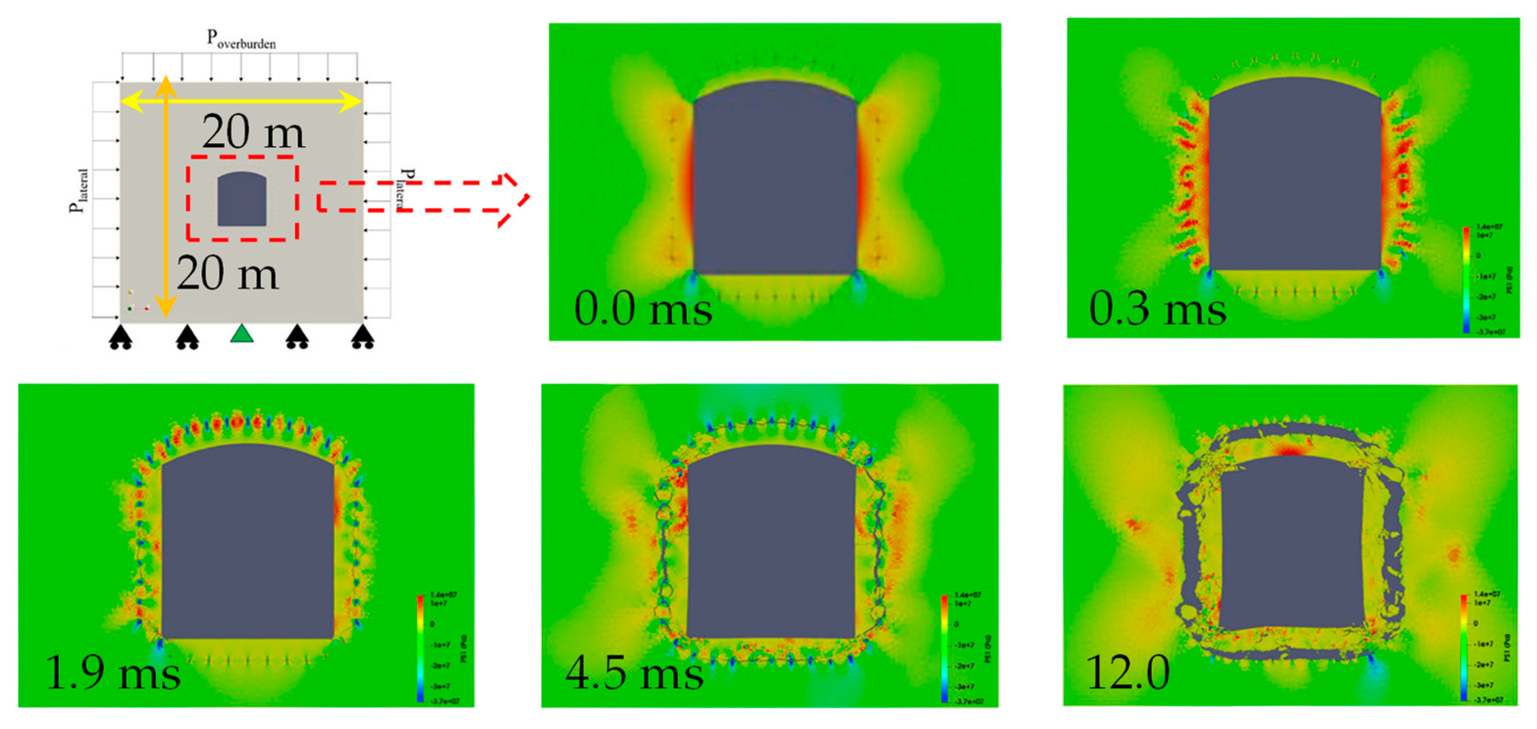
Munjiza et al. [147] first applied FDEM to model blast-induced fragmentation, which implemented a simple gas zone model to address the gas penetration and fracture opening resulting from the gas pressurization caused by rock blasting, which, did not account for the influence of geological discontinuities on the process of rock fracture. An et al. [3] conducted comprehensive blasting modellings with HFDEM IDE2D to simulate the blast-induced rock fracture, fragmentation and fragment muck-piling process, which considered not only the transition from continuum to discontinuum resulting from fracturing but also the effects of the blast-induced gas expansions and flows, loading rates, and reflective/absorbing boundaries on the dynamic fracturing process. The modelled crushed and cracked zones as well as propagations of long radial cracks by a single borehole blast are compared with those in the literature. It also examined the fracturing process and the subsequent fragment ejection as well as the muck-piling mechanism resulting from the simultaneous, consecutive, production and controlled blast. FDEM has proven to be a useful tool for researching rock blasts, despite a number of constraints including an idealized pressure-time interaction, small time integration steps, and grid-dependent crack propagation and 2D modelling. FDEM effectively captures stress wave transmission, reflection and dissipation, the flow of detonation gases across the fractured rock, the development of the crushed and cracked zones, the initiation and propagation of long radial cracks, reflective wave-induced tensile failures at reflective boundaries, and the influence of diverse rock and detonation properties on the fracturing process of rocks during blasting operations. Fukuda et al. [133] parallelized HFDEM IDE2D properties based on GPGPU and further developed it by implementing a non-reflecting boundary to model infinite rock mass and an empirical pressure-time function to model blasting-induced pressure evolution, who then applied the GPGPU-parallelized HFDEM2D to simulate the dynamic fracture process by blasts in finite and infinite rock masses. Han et al. [148,149] implemented the GPGPU-parallelized HFDEM2D to investigate the process of rock fracture and fragmentation alongside the formation of the excavation damaged zone (EDZ) resulting from controlled contour blasting in a deep tunnel characterized by elevated in-situ stresses in Sweden. This approach integrates the in-situ stresses, blast loading, and fracturing under tension and shear with gas flowing through fracture-induced loads, facilitating the representation of intricate dynamic interactions resulting from several blast cycles. It is found that, during smooth blasting under elevated in-situ stresses in the horizontal direction, detonation-induced fractures initially propagate along the horizontal direction, even with decoupled holes, and coalesce into larger cracks later, hindering smooth tunnel perimeter formation and expanding the EDZ. When long fractures spread horizontally, smoother surfaces are produced at the crown and invert. The interaction of the free surfaces from the neighboring blast-holes as well as the major principal stress from the in-situ stresses causes failures in the bottom section of the tunnel lateral walls to propagate upwards at an angle of 60 degrees from the vertical, aligning well with field test measurements. Moreover, Han et al. [150] applied the same FDEM to initially simulate the rock fracture process triggered by destress blasting in a single borehole, replicating a real blast in a deep gold mine with high in-situ stresses. Then, a two-step tunnel face excavation in a deep mine with high in-situ stresses is simulated to reproduce the incident of the excavation-induced rockbursts. Destress blast-holes are finally introduced into the same numerical model before the excavation to assess their effectiveness in mitigating the excavation-induced rockbursts. The results show that the fractures caused by destress blasting displace the excavation-induced high abutment pressure away from the tunnel face, thereby protecting the wall from fracturing. Thus, the numerical simulations indicate that the effectiveness of destress blasting in mitigating excavation-induced rockbursts is influenced by both the site-specific conditions and the destress blasting designs, including the configuration of boreholes and the placement of explosive charges.
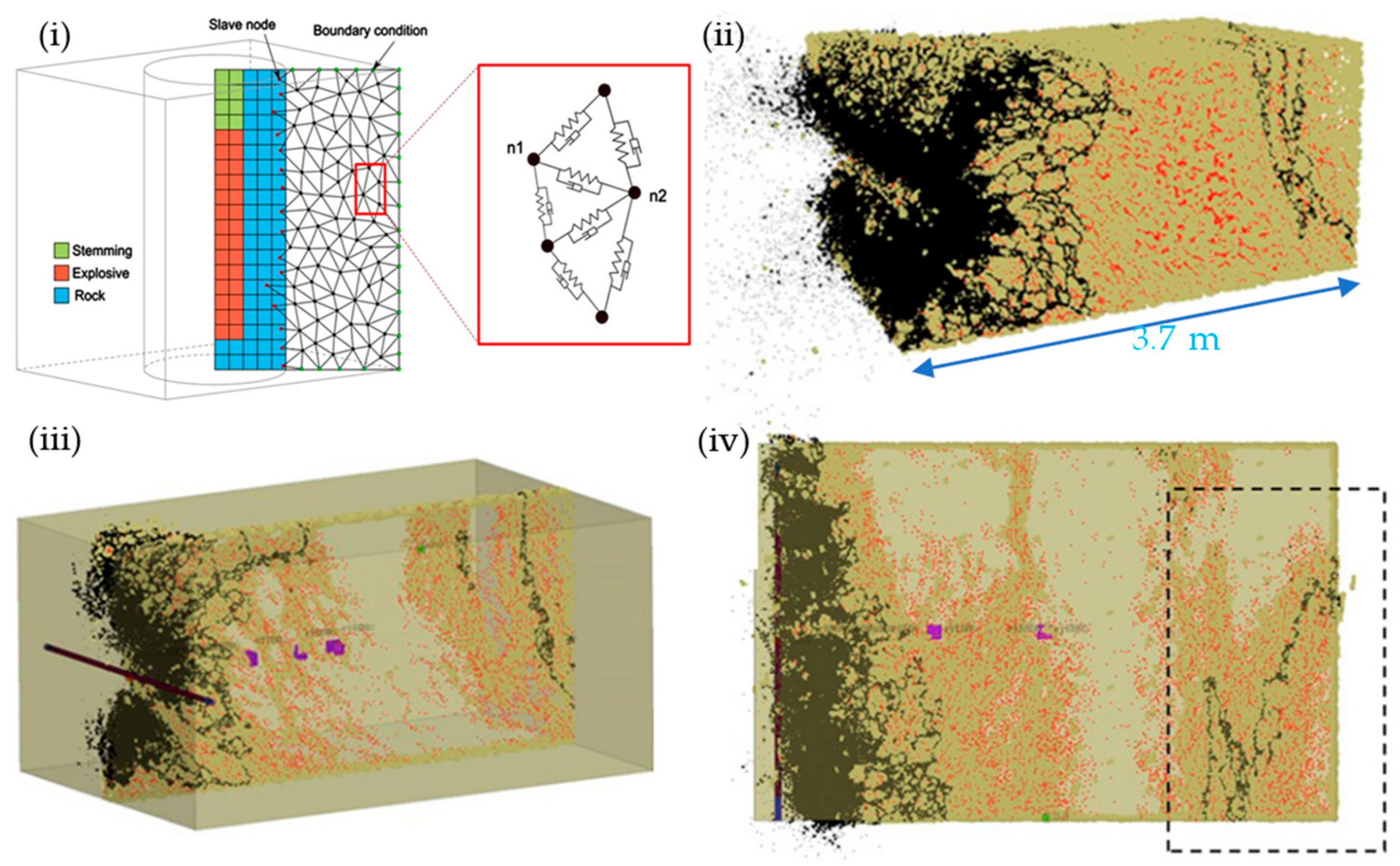
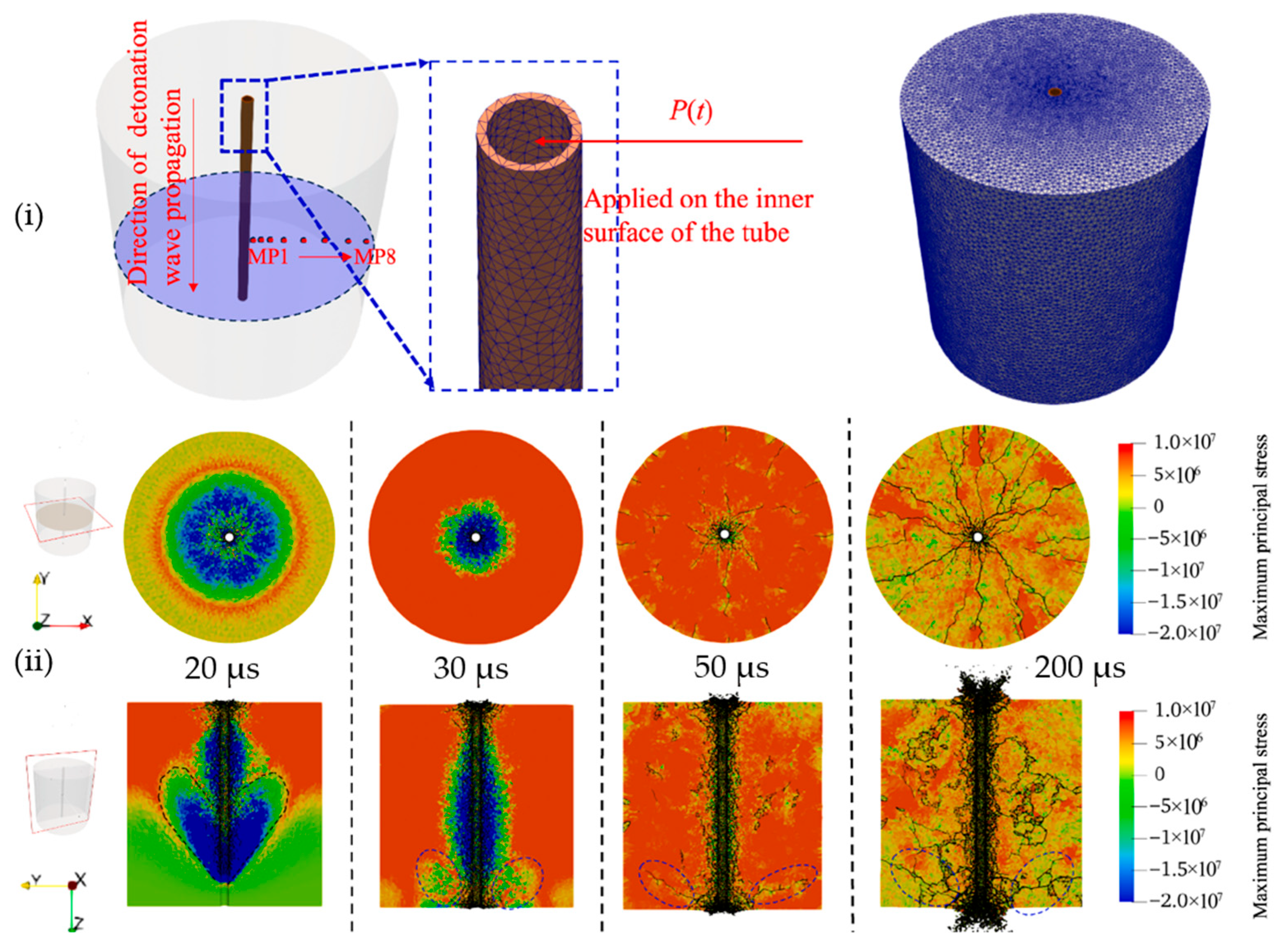
Moreover, Yang et al. [151,152] modelled the process of fracturing and fragmentation caused by a blast in fractured rock using FDEM with a fully coupled fluid-solid interaction model. Munjiza et al. [153] implemented an innovative fluid-solid interaction solver into FDEM through a novel immersed boundary method, enabling the simulation of both rock deformation and fracture caused by blasting and complex blasting-induced fluid flow through fracturing rock. Furthermore, Lu et al. [154] employed FDEM to investigate the effect of in-situ stress, hole spacing and radial decoupling coefficients on the superposition of blasting stress and the cracking features between holes, which concluded that the holes of smooth blasting should be aligned with the direction of the maximum principal stress to promote crack formation between holes and achieve smoother wall excavation. Raghavaraju and Mohanty [155] implemented a finite volume solver for explosives into Y-code to model rock blasting. Nevertheless, all these simulations were limited to 2D. To advance beyond this limitation, Lei et al. [156] first utilized their in-house FDEM code parallelized for running on supercomputers with 540 processors to three-dimensionally simulate explosive effects, irregular geometries as well as fracture initiation and propagation by rock blasting in block cave mining. Liu et al. [157] implemented the GPGPU-parallelized HFDEM3D to simulate the process of rock fracture and fragmentation caused by a single borehole detonation as well as simultaneous and sequential detonations of various boreholes. Wu et al. [158] then implemented the extrinsic cohesive zone model into the GPGPU-parallelized HFDEM3D through an innovative and straightforward master-slave algorithm to model the blasting test reported by Banadaki [159], which consisted of a cylindrical rock featuring a single blasthole along with a hollow copper tube, as shown in Figure 11(i). Figure 11(ii) shows the spatial distribution of the maximum principal stresses on two distinct planes, which indicates the most tensile stress. Notably, the stress propagation and fracture evolutions depicted in Figure 11 closely resemble those seen in 2D blasting simulations, though the overall 3D fracture pattern proved significantly complex. In addition, Lisjak et al. [160] implemented the Irazu FDEM3D code to investigate the potential effectiveness of an innovative pulsed combustion-based dynamic fracturing simulation technology for pre-conditioning rock mass in in-situ recovery mining applications.

3.6. Modelling Rock Dynamic Fracture and Blasting Using Other Numerical Methods

As reviewed by Jing and Hudson [35] and Mohammadnejad et al. [2], there are many other numerical methods applied in the literature to model rock fracture, which include the finite difference methods such as FLAC (e.g., [161,162,163]), boundary element methods such as displacement discontinuity method and its variations (e.g., [164]), smooth particle hydrodynamics (e.g., [165,166]), lattice spring model (LSM) (e.g., [12]), phase-field methods (e.g., [167,168]), and peridynamics (e.g., [169,170]). However, these methods are seldom applied to model rock dynamic fractures or rock blasting except for a few of them [12,169,170], which are then omitted from this review.

4. Discussions and Prospects of Modelling Rock Dynamic Fractures and Blasting

As reviewed above, rock dynamic fracture has wide applications in civil, mining, environmental and energy engineering, which is thus worth studying. Compared with rock fractures under static/quasi-static loads, rock dynamic fracture is more complex and has a number of peculiarities such as rate dependency as summarized in Table 1. These peculiarities of rock dynamic fracture and its application in rock blasting have been studied using various numerical methods in the literature, which are reviewed in Section 3 with a focus on modelling them with FEM, DEM and FDEM.

4.1. Discussions and Research Gaps in Modelling Rock Dynamic Fracture

Table 2 summarizes the strengths and limitations of these numerical approaches for simulating rock dynamic fractures.
Table 2 and the reviews in Section 3 depict that FDEM is the most promising method for modelling rock dynamic fracture and its application in blasting. In engineering applications involving large, relatively uniform rock masses under moderate loading conditions, FEM offers an efficient approach due to its capability in simulating continuous material. FEM is prevalently used due to its established maturity, effectiveness in modelling rock inhomogeneity and nonlinearity, and the accessibility of numerous validated commercial software for both large- and small-scale issues. The extended, meshless or particle FEM approaches have gained increasing attention in the field of rock dynamic fracture, primarily due to their adaptability in meshing and ability to simulate the fracture progression evolution without the need for remeshing. In cases when rocks exhibit significant discontinuities, such as jointed, multifaceted, or extensively fractured formations, DEM serves as a robust numerical modelling tool due to its suitability in managing a substantial quantity of fractures. However, DEM requires exceptional computational effort in terms of both memory and processing time, even for a comparatively large quantity of particles/blocks. An additional key limitation of DEM is the uncertainty associated with the geometry of the fracture system, whose influence remains difficult to evaluate. Furthermore, DEM usually requires 3D simulations, with 2D simulations only for generic studies. FDEM inherits all advantages of FEM and DEM and overcomes most of their disadvantages but is exceptionally computationally intensive. Compared with FEM, FDEM is more efficient and robust after damage and failure occur, especially in terms of modelling fragment movement, interaction and muck-piling such as secondary and tertiary fractures resulting from fragment interaction. Compared with DEM, FDEM offers greater versatility in modelling rock deformability prior to fracture, initiation and propagation of cracks during fracturing, as well as the subsequent movements of irregularly shaped fragments post-fracture.
In summary, despite significant advances in modelling rock dynamic fracturing with FEM, DEM and FDEM, there are still many research gaps in modelling it, some of which are highlighted in the following sections.

4.1.1. Research Gaps in Modelling the Dynamic Properties of Rocks and Discontinuities

As reviewed in Section 2, the mechanical properties of rocks, including the discontinuities under impact loads, are related to loading rates. Unfortunately, most modellings reviewed in Section 3 adopt the static mechanical features of rocks to analyze the dynamic fracture of rock by blast. Furthermore, while extensive laboratory research has been conducted on the dynamic mechanical features of rocks, studies focusing on dynamic mechanical features of discontinuities are rarely incorporated into the computational models of rock blasting. Consequently, the utilization of dynamic mechanical characteristics of rocks, including discontinuities along with their constitutive interactions accounting for the loading rate in computational models, may serve as a future research topic for rock blasting.

4.1.2. Research Gaps in Modelling the Heterogeneity of Rocks Under Dynamic Loads

Rock microstructure governs rock dynamic fracturing behaviors and therefore the phenomenological response of the rocks. Thus far, material heterogeneity is currently incorporated into some computational approaches to study the impact of rock heterogeneity on dynamic rock failure and corresponding energy release as reviewed in Section 3. However, no models reviewed above are perfect, as they all need to be elucidated to facilitate the comprehension of intricate rock microstructure, saying nothing of the heterogeneity of rock masses. Therefore, the modelling of the rock heterogeneity effect under dynamic loads in rock blasting using 3D models at a technical level requires further investigation. To simulate rock heterogeneity, normal or Weibull distribution [172] are widely adopted. However, the use of 3D scanning and printing provides a promising pathway to incorporate the intrinsic randomness of rocks into computational models.

4.1.3. Research Gaps in Modelling Existing Discontinuities and New Fractures in 3D

All continuous and discontinuous methods have limited ability to mimic the interaction involving pre-existing discontinuities and emerging fractures in rock masses. The hybrid methods have enhanced capabilities but usually model the interaction in 2D. However, the discontinuity comprises two irregular edges, which may be in contact or filled with soft rocks or clays. Due to their finite width and length, representing them as 2D lines undermines model accuracy. As such, future research should focus on 3D models that represent both natural discontinuities and dynamically evolving fractures induced during rock deformation.

4.1.4. Research Gaps in Modelling the Detonation of Explosives and Detonation-Induced Gas Flow Through Fracturing Rock Mass

Most studies on modelling rock blasting reviewed in Section 3 adopted the pressure-time relationships calculated using empirical or theoretical equations of state (EoS) to model the detonation-induced pressure applied to the boundary of the borehole, which presents numerous constraints and incorporates several simplified approximations of the intricate chemical process. Furthermore, the rock mass surrounding the borehole lacks the development of the cracks and the crushed region as the detonation gas expands; as a result, the detonation gas passes through the crushed region and the cracks spread out from it. This is entirely disregarded or oversimplified in the studies. More sophisticated modeling approaches are needed to realistically simulate these complex interactions.

4.1.5. Research Gaps in Modelling the Multiphysical Coupling Process in Rock Blasting

Impact-induced rapid deformations in rocks can result in high temperature increases in localized areas due to adiabatic heating. The high temperatures may cause thermally induced damage in the rocks and then influence their mechanical behaviors. The coupling of thermal and mechanical interactions can result in the complex behavior of the rocks. In rock blasting, the detonation-induced high temperature may trigger transformations in the mineral phases of rocks around the borehole, while the detonation-induced stress wave can result in complex multi physical coupling processes in the rock mass with fluids filled in discontinuities. Thus, multi physics coupling is an essential element of rock blasting, encompassing the complex thermal (T), hydraulic (H) and mechanical (M) interaction processes, which, however, are ignored or simplified in almost all modellings reviewed in Section 3.

4.2. Hybrid Finite-Discrete Element Method (HFDEM) for Modelling Rock Dynamic Fracture and Its Application in Rock Blasting

The authors have been attempting to address some of these research gaps identified in Section 4.1 by developing an HFDEM to simulate the dynamic fracture of rocks by impact load and blasting. Some progress is presented in the following sections. HFDEM was originally developed by the authors [113] using Visual C++ and OpenGL on the basis of the Y libraries made available by Munjiza et al. [111,173]. It has since been applied to simulate a variety of rock mechanics simulations [174], joint shear tests [175] and shallow rock blasting [3] and is now a powerful computational method to evaluate rock fractures. To address the constraints of sequential coding and to achieve efficient computational time for realistic 3D simulations, the authors [134] parallelized HFDEM2D/3D with a compute unified device architecture (CUDA) C/C++ to run on GPGPU accelerators. This development enabled full parallelization on GPGPU, limiting sequential processing to input/output tasks. While the data transfer to the host computers from the GPGPU devices is required to calculate the results, these are typically negligible unless very frequent. To further optimize the performance of modeling dynamic rock fracture, Fukuda et al. [139] incorporated a new contact activation method that significantly boosted computational efficiency and enhanced the stress wave modelling accuracy. Additionally, HFDEM was structurally updated to decouple from the visualisation interface, making it operational on Linux-based supercomputers and compatible with the Visualisation Toolkit-powered tools including Paraview. Furthermore, several novel, efficient and practical algorithms have recently been integrated into HFDEM for diverse applications. These include the implementation of an adaptive contact activation approach to significantly reduce contact interaction calculations, a mass scaling technique to increase stable time steps for 3D quasi-static triaxial compression modelling [176], a local damping scheme design to enhance the efficiency of geostatic analysis of tunnelling under in-situ stresses [148] and destress blasting [150] simulations, grain-scale and statistical heterogeneities for multi-scale grain-based simulations [177], the elasto-plastic model for modelling the plasticity of solid elements under excessive stresses induced by impacts [140], the extrinsic cohesive zone model based on a novel master-slave algorithm to improve computing efficiency and accuracy [158], the innovative two-stage approach to model dynamic fracture and fragmentation of rocks under multiaxial coupled static and dynamic loads [178] and the strength reduction method to investigate slope instabilities [179]. Some key features of HFDEM for modelling rock dynamic fracture and its application in rock blasting are briefly introduced in the following sections, while the fundamentals of FDEM for modelling continuous deformation using continuum mechanics, transition from continuum to discontinuum through cohesive zone model and discontinuum behaviour using potential-based contact mechanics are omitted, which can be found in excellent literature [134,139].

4.2.1. Modelling Loading Rate Effects on Rock Dynamic Behaviour

As reviewed in Section 2, the strength and other properties of rocks generally increase with increasing loading rate. Various methods have been implemented in HFDEM to model the effects of loading rate, which include rate-dependent cohesive zone model, empirical equations and adjustments of input parameters.
The cohesive zone model exhibits rate dependency to a certain degree [180,181]. Figure 12(i) compares the correlation between apparent (bulk) dynamic tensile strength and apparent strain rate derived from HFDEM simulations with testing in the laboratory of dynamic spalling tests [180], which shows that the overall trend of the dynamic tensile strengths of rocks under various strain rates simulated by HFDEM captured well that obtained in the laboratory experiments, despite the use of singular input rock attributes selected in their study [180] while varying the applied loading rate. Moreover, Figure 12(ii) compares the stress–strain relations derived from both the HFDEM simulations and the laboratory experiments of the dynamic compression tests on approximately jointed granite specimens at varying loading rates, which further proves that HFDEM can capture the rate effects to a certain extent, despite the singular input rock parameters specified in their study [169] while altering the applied loading rate.
A semi-log relation in Equation (1) proposed by Zhao [21] for relating rock dynamic compressive strength (UCS) with loading rate was implemented by An et al. [3] into HFDEM to model rock blasting
σ c d = A · l o g σ ˙ c d σ ˙ c + σ c
where σ c d is the dynamic UCS in MPa, σ ˙ c d is the loading rate in MPa/s, σ ˙ c is the static loading rate, σ c is UCS at the loading rate and A is a material feature contingent upon lithology. Zhang et al. [27] developed a similar formula to Equation (1) to corelate dynamic fracture toughness with static one. HFDEM does not directly adopt the fracture toughness as an input parameter but instead uses fracture energy release rate to control the post-failure softening process and the ultimate opening displacement in the case of tensile failure or the residual sliding displacement in the case of shear fracturing. The rock blast modelling was simplified by plane strain considered in An et al. [3], G f I = K I 2 1 v 2 / E , where G f I is the mode I fracture energy release rate, KI is the mode I fracture toughness, v is the Poisson’s ratio and E is the elastic modulus. In accordance with this, it is assumed that the dynamic fracture energy rate will rise with the loading rate, as determined by the dynamic BTS tests.
However, Han et al. [178] demonstrated that the rate-dependent cohesive zone model and empirical Equation (1) were still insufficient to capture the effects of loading rate on rocks. A simple but effective modelling scheme is then applied to fully capture the rate-dependent fracture behaviors of rocks under multiaxial coupled static and dynamic loads, in which, even with identical loading rate, distinct input attribute combinations for rock are applied to fully capture the strain rate-dependent dynamic behavior of rock induced by the micro-structure changes due to confinements. This scheme is adopted by others [182] applying FDEM to model dynamic rock fracture in percussive drilling. Nevertheless, further developments are still needed to implement more advanced models such as Holmquist–Johnson–Cook (HJC) and Riedel–Hiermaier–Thoma (RHT) [81] into HFDEM, which are rate-dependent frameworks frequently employed to simulate the dynamic fracturing of rocks.

4.2.2. Modelling Stress Wave Propagation, Reflection and Absorbing as Well as Stress Wave-Induced Fracture

HFDEM formulates the equation of motion of intact solids under loads within the context of the explicit FEM, which is solved using the explicit time integration with the central difference scheme. Thus, HFDEM can naturally model stress wave propagation in intact solids. Moreover, HFDEM naturally considers all boundaries as reflection boundaries. The absorbing boundaries are implemented into HFDEM by viscous boundary tractions in the literature [65,183]. The normal and tangential boundary tractions (tn, ts) applied to the boundary perpendicularly and tangentially, respectively, are given by Equation (2):
t n t s = ρ V p v n V s v s
where Vp and Vs are the P- and S-wave speeds, respectively, of the boundary while vn and Vs are the particle velocities perpendicular and tangential, respectively, to the boundary. To mitigate the impact of blasting-induced stress wave, the computed normal and tangential tractions are converted into equivalent nodal forces and applied at the boundaries. This setup ensures that the non-reflective boundaries effectively absorb the stress waves regardless of their direction.
Fukuda et al. [133] applied HFDEM2D to simulate the stress wave propagation and dynamic fracture by blast in a circular rock specimen with reflective and absorbing boundaries, as shown in Figure 13(i). The stress wave commences to propagate radially from the blast hole following the blast. The leading edge of the major principal stress wave exhibits compression (cold colour), signifying that both the circumferential and radial stress components are compressive. The imposed stress condition results in the development of shear fractures in the crush zone of the blast hole. A tensile stress wave represented in warm colour follows the compressive stress wave front, initiating the tensile cracks that radiate outwards. In case 1, the compressive stress wave front does not reflect upon reaching the external boundary while it reflects to generate a tensile stress wave propagating back to the borehole in case 2. Wu et al. [158] extended the problem into 3D and further investigated the stress wave propagation and dynamic fracture by blast in a cylindrical rock specimen with reflective boundaries using HFDEM3D and illustrated the significance of the impact of stress wave on rock fracture patterns. Figure 13(ii) illustrates the simulated fracture patterns on three slices perpendicular to the axis of the borehole, which are compared with those from the experiments by Banadaki [159]. The upper slice features multiple radial cracks, while the middle slice displays both the radial fractures and circumferential fractures. The bottom slice reveals a dominant radial fracture alongside more pronounced circumferential fracture than the middle slice. Wu et al. [158] attribute this to the 3D nature of the stress wave propagation and reflections inside the cylindrical rock, resulting in conical tensile fracture. When viewed on lower horizontal slices, they appear as a circular crack pattern.

4.2.3. Modelling Explosive–Rock Interaction Including Detonation-Induced Gas Expansion and Flow Through Fracturing Rock

In HFDEM, three approaches are implemented to model the explosive–rock interaction, which include pressure–time histories, Duvall-type pressure function and pressure–volume histories. According to the majority of current methodology for rock blasting simulation, the empirical pressure–time equation of state is implemented to model the explosive generated gas pressure although it involves various approximations. For example, in the authors’ early study [113], the chemical response occurring during a blast is simulated using the commercial explicit finite element software AUTODYN to establish a correlation between the blast-induced instantaneous gas pressure and time, which is then implemented into HFDEM. A Duvall-type pressure function proposed by Cho and Kaneko [65] is incorporated by Fukuda et al. [133] to simulate the pressure rise and decay period during the blasting process, as shown in Equation (3)
P = P 0 ξ ( e α t e β t ) where   ξ = 1 / e 0 α t e 0 β t and   t 0 = 1 / β α log β / α
where P0 represents the peak blasting pressure applied to the wall of blast-hole, t0 depicts the time taken for the pressure to rise, t is the ongoing simulation time, and constants α and β which are characteristics of explosives, and P(t) indicates the instantaneous pressure on the blast-hole wall and surrounding fractures within the gas-filled zone. This equation enables dynamic control over pressure evolution by modifying β/α and t0, providing computational efficiency. This equation streamlines the process of computation and mitigates the complexity in computational methods; however, identifying a suitable decay time ratio in a practical blasting scenario often poses a challenge. In particular, for every blasting instance, the reduction of blasting pressure correlates with the expansion of gaseous products, resulting in distinct pressure–gas volume trajectory for each blast-hole case.
An equation of state (EOS) is implemented by Han et al. [148] into HFDEM to account for the effects of fracture propagation and stress redistribution during the deformation of blast-holes rather than assuming uniform responses across the blast-holes. This approach generates a pressure–gas volume history curve based on field-specific data and explosive properties. The formulation details of explosive, the ideal velocity of detonation (VOD) of the explosive, charge configuration parameters and estimated peak pressure on the blast-hole wall are processed through ideal detonation code [184]. This code simulates pressure decay curve in response to increasing gas volume, especially during initial expansion. A pressure decay function is then fitted and incorporated into HFDEM. The initial volume of each borehole, even if deformed, is calculated by identifying the surface edges, calculating the Centre and area of the borehole. As blasting progresses, the model tracks the expansion blast-hole due to the detonation-induced gas pressure by detecting broken cohesive elements and summing their areas, which, together with the area of blast-hole captures realistic pressure evolution. In the context of contour blasting analysis under high horizontal in-situ stress at TASQ tunnel (Aspo Hard Rock Laboratory, Sweden), Han et al. [148] applied HFDEM to investigate rock fracture and fragmentation. According to Olsson et al. [185], the explosive Dynotex 1 (17 mm diameter) was used. Its formulation, based on technical datasheet, comprises 88% ammonium nitrate and 12% ethylene glycol dinitrate with an ideal VOD of 7 km/s in its decoupled form. The peak pressure on the borehole wall is estimated as 100 MPa through a combination of Cunningham’s [184] and Starfield’s model [186], incorporating key parameters of explosives such as the charge diameter, density and decoupling ratio derived from field test [185]. This information is entered into the ideal detonation program [184] to generate the blasting pressure decay vs. increasing volume curve. It was observed that during the decay period, the pressure–gas volume relationship can be completely characterized using the exponential model depicted in Equation (4).
P ( t ) P m a x = 0.99858 V ( t ) V 0 1.34088
where Pmax depicts the peak pressure acting on the borehole wall and V0 is defined as the initial blast-hole volume. However, it is worth noting that the pressure–gas volume history curve characterizes the pressure decay phase. Therefore, to simulate the increase phase, a reasonable assumption regarding the loading time must be made to avert infinite frequency response and potential numerical instabilities. Since deep tunneling blasting simulations are typically based on plane strain conditions, the rise time of pressure for each blast-hole is determined as time taken for detonation wave to cover 1 m distance. A linear time–pressure relation is often employed (e.g., [187,188,189]), where the blasting pressure increases linearly until it reaches its peak. For example, as demonstrated by Han et al. [148], the rise time equals 1/VOD (140 µs), implying the pressure peaks once the shock fully propagates through 1 metre. As the detonation gas expands and decays, further crushed zone cannot be formed any longer in the rock mass surrounding the blasthole. Consequently, the gas passes through the crushed zone to generate cracks propagating through it. Simultaneously, the gas applies pressures on the boundaries of the crushed zone and cracks to induce further crack propagation. To simulate this process, An et al. [3] incorporated a simplified gas flow model into HFDEM, which specified a gas zone based on the stress wave propagation speed and current observation location. The explosive gas is confined within the gas zone, represented as a circle around the borehole. The spatial and temporal pressure variation within this region is computed using an iterative algorithm described by Munjiza et al. [147], ultimately delivering the distribution of gas pressure from the detonation.
To refine the depiction of rock failure under blasting, Han et al. [148] applied the detonation pressure across the blast-hole boundary and the evolving fracture network stemming from it. The model simplifies gas movement as a zone expanding from each blast-hole. At each simulation increment, this pressure is exerted on the broken cohesive elements within the gas zone. The chosen flow rate reflected the specific characteristics of the model and adhered to documented findings on gas flow aperture relationships [190,191,192]. Han et al. [148] utilized a 40 m/s of gas flow rate in their model for gas zone expansion during blasting relying on the correlation between gas flow rate and fracture aperture described by Furtney et al. [192]. Liu et al. [157] extended the 2D explosive–rock interaction modelling procedure into 3D to study rock fracture and fragmentation from various blasting setups, including multiple borehole detonations. In Figure 14, a ring blast simulation is depicted where a central borehole is firstly ignited from the bottom and detonated upwards, creating high compressive stress waves that fracture the rock. Neighboring boreholes are then detonated simultaneously from the central borehole outwards. The detonation begins at the bottom of the central borehole, followed by sequential detonation of adjacent boreholes to the left and right, continuing until the boreholes in the far left and far right sides are detonated. The blast-generated rock fragments subsequently collapse and fall outwards, and the fragmented rocks collapse. Still, the explosive–rock interaction modelling procedure, especially the gas flow model in use, remains oversimplified and may inaccurately estimate gas effect on long radial cracks. Kamran et al. [193] addressed this by integrating one-dimensional transient flow model based on momentum and conservation of mass [194,195] into HFDEM3D, solved through an explicit time integration scheme to determine gas pressure along the fractures. Furthermore, the fluid dynamics of the detonation-induced gas should be implemented into HFDEM through fluid–structure interactions between the gas and fracturing rock, as demonstrated by Munjiza et al. [153] and Fukuda et al. [196].

4.2.4. Modelling Dynamic Fracturing Under Coupled Static and Dynamic Conditions

Most dynamic rock fracture modellings reviewed in Section 3 are conducted under free stress conditions. However, the dynamic rock fractures in engineering are usually accompanied by coupled static and dynamic loads such as underground rock blasting under in-situ stresses. Similar to prevalent explicit FEM software, a dynamic relaxation scheme with artificial viscous damping can be used in FDEM to apply static stress, whose convergence rate, however, is very poor as noted by Fukuda et al. [133]. An innovative and fast two-step approach integrated with the schemes of mass scaling and local damping is implemented into HFDEM to simulate the dynamic fracture of rocks under coupled static and dynamic loads. Han et al. [178] applied HFDEM3D with the two-step approach to build a 3D numerical model of the triaxial split Hopkinson pressure bar testing system simulating rock dynamic fracturing in dynamic uniaxial, biaxial and triaxial compression (UC, BC and TC), as shown in Figure 15. Initially, static stress equilibrium across the entire model, including the rock and all bars of the testing system, is established under the confining pressures. In the subsequent step, dynamic loads are introduced while maintaining the established static pressures. During the first step, the target confining pressures of (10, 0, 0 MPa), (30, 10, 0 MPa) or (30, 20, 10 MPa) in the case of dynamic UC, BC and TC tests, respectively, are applied at the external ends of the bars (in X, Y and Z directions, respectively) through the boundary of pressure tractions while the inner ends interfacing with the rock remain fixed. The static equilibrium in the metal bars is achieved using optimized mass scaling and local damping with the time step dt = 1 s according to Equation (5), which only takes 3 min:
M scale 2 u / t 2 = f tot + α f tot sgn ( v )
where Mscale denotes the adjusted lumped mass, ftot represents the nodal out-of-balance-force, v refers to the nodal velocity, ||ftot|| is the magnitude of each component of ftot, sgn(∙) is the sign function automatically derived from sign of (∙) and α is the local damping coefficient. Then, by recovering the rock part into the system and the contact interaction between rock and metal bars, the static equilibrium of the complete system is reached with the minor mass scaling and local damping approach with dt = 5 ns, which takes 893 min. This method accommodates both the intact rock modelling and rocks with significant pre-existing cracks or fractures. In the next step, dynamic loading is applied at the external end of the incident bar in the Y direction while the confinements at the transmission and reflection bars remain unchanged. Figure 15(i) illustrates the modelled wave propagation with the directional stress σ x x in the metal bars after dynamic impact is applied in the case of the dynamic TC test. Figure 15(ii) compares the simulated stress wave profiles with those from laboratory experiments, which agree well with each other. Figure 15(ii) depicts the modelled dynamic fracture process from dynamic UC and BC tests. In UC, the rock is broken into many small fragments through the initiation and propagation of cracks due to high-impact velocity. In BC, cracks are first initiated from lateral ends of the free surface and then propagate towards each other to coalesce at a certain depth, converging into a V-shaped rock slab. Moreover, the simulated results vividly exhibit the confinement dependence of the dynamic behaviours of rocks in the testing system. The results also highlight confinement-dependent rock behavior, indicating the separate input parameter sets are essential for capturing the actual rate-dependent responses under varying confinement.
Furthermore, Han et al. [148] applied HFDEM2D with the two-step approach of integrating local damping, mass scaling and critical damping for applying coupled static and dynamic loads to simulate the contour blasting-induced excavation damage zone during tunnelling with high in-situ stresses at the Aspo Hard Rock Laboratory in Kalmar County, Sweden. At the tunnel site, contour blasting take place where the in-situ stresses acting vertically and horizontally directions perpendicular to the tunnel are 10 MPa and 30 MPa, respectively. As shown in Figure 16, there are 38 contour boreholes with the diameter of 48 mm each around the tunnel already excavated by drill and blast from the previous excavation step. The spacing between any two adjacent boreholes is 0.45 m and the burden is 0.5 m. The first step applies the local damping and mass scaling technique to simulate the stress field due to in-situ stress, storing the nodal coordinates for the second step. The in-situ stresses are imposed through applying pressure tractions on two lateral sides and the top boundary. After equilibrium is reached, the smooth blasting occurs in 4 successive stages: first, 16 sidewall blast-holes are detonated; second, 11 crown boreholes detonate 1.5 ms later; third, 5 bottom blast-holes detonate at 2.0 ms; and finally, 6 bottom boreholes detonate at 3.5 ms. The blasting simulation concludes when fracture propagation ceases due to dissipating stress wave and gas pressure, as shown in Figure 16.

4.2.5. Modelling the Dynamic Fracture of Heterogeneous Rock and Rock Mass with Pre-Existing Discrete Fracture Network

Rocks are usually heterogeneous, and thus the dynamic fractures of rocks are often affected by rock heterogeneity. Various methods have been implemented into HFDEM to consider rock heterogeneity, which includes grain-based modelling, statistical method and explicit defect modelling. In grain-based HFDEM, 3D polyhedral grains of target are created using the open-source Neper 3.4.0 software [197], a robust tool for generating and meshing polyhedral grains with multiscale tessellations. The mesh data is then used as an input to HFDEM to simulate the rock dynamic fracture process. The main objective of grain-based modelling is to replicate the microstructure of heterogeneous rocks and explore how mineral-scale heterogeneity affects the dynamic failure process. However, modelling each individual mineral grain is computationally expensive and time-consuming, even with advanced parallel computation in the grain-based modelling method. For example, Yahaghi et al. [177] applied the grain-based modelling method of HFDEM to simulate the failure process of fine-grained sandstone, in which a substitute approach was introduced to solve the issue and model the fine grains as a statistical conglomerate composed of multiple minerals together with their cementation and voids. In each conglomerate complex, heterogeneity is introduced by specifying its main physical-mechanical properties adhering to statistical distributions, including Weibull’s distribution. The cumulative distribution formula of the Weibull distribution can be given by Equation (6):
P σ = 1 e x p σ σ 0 m  
where P   ( 0 P 1 ) denotes the probability, σ represents the parameter, σ 0 is the initial parameter, and m indicates the homogenization index. The following Equation (7) is readily obtained according to Equation (6):
σ = σ 0 l o g 1 P σ 1 / m
In Equation (7), each value of P is produced utilizing the widely recognized Mersenne Twiser random number generation method. Then, the heterogeneous grains are tessellated to represent the microstructure of heterogeneous rocks. Figure 17 illustrates the fracture pattern of Tasmanian sandstone modelled with the grain-based HFDEM using the concept of conglomerate grains, which classifies different minerals, voids, cementation, clay and silt in Tasmanian sandstone into three types of conglomerate grains, namely, low-strength grain (LSG), medium-strength grain (MSG) and high-strength grain (HSG) [177]. It can be seen from Figure 17 that the primary macrocrack responsible for rock failure is typically a transgranular crack, which emerges from the linking of smaller macrocracks. The magnified cross-section in Figure 17 illustrates that grain boundary and intragranular fractures are largely present in HSG and MSG while MSG undergoes failure via intergranular and transgrannular fractures. This pattern arises because once microcracks reach LSG at the point of failure, this grain cannot accommodate the deformation, leading to microcracks through it. Figure 18 models the dynamic shear fracture of heterogeneous granite under static and dynamic coupled loads in triaxial SHPB testing system-based dynamic shear tests with the grain-based HFDEM, which is applied to illustrate the mineralogical complexity of granite and identify fracturing that occurs at numerous scales under dynamic shear stresses.
In addition, geological discontinuities in rock masses, such as joints, faults and bedding planes, can considerably influence the dynamic fracture of rocks. These discontinuities change the way blasting-induced stress waves reflect and pass through the rock, which in turn directly affects how the fractures form and propagate. Han et al. [150] applied HFDEM to investigate the effects of pre-existing bedding planes, including empty blast holes, on the fracturing behaviour of rock mass by destress blast in deep underground sites with high anisotropic stresses of 100 MPa and 50 MPa in the vertical and horizontal directions, respectively. As presented in Figure 19, when rock has horizontal bedding planes, the area around the blast-hole exhibits denser fractures and extended horizontal fractures at the lateral sides. This pattern is mainly due to stress wave reflections off these bedding planes. The stress waves transform as they traverse the bedding planes, which alters the fracture behaviour further from the blasthole. Vertical bedding planes, however, serve more effectively for crack propagation, unlike horizontal bedding planes where high vertical in-situ stress reduces this effect. The findings by Han et al. [150] suggest that the effect of the bedding planes on blasting-induced rock fracture propagation is largely dependent on the in-situ stress regime. The resultant fracture pattern emanates from the joint effect of the in-situ stress and behavior of stress waves as they encounter and traverse the bedding planes. The effect of more complex discrete fracture networks on the rock fracture process can be modelled with HFDEM as well, as demonstrated by Han et al. [179], who investigated the entire progressive landslide process of a natural slope containing complex discontinuous joints, considering different connectivity rates, spacings and dips.

4.2.6. Modelling Dynamic Fracture-Induced Fragment Size Distribution

Fragment size distribution is an important index to quantitatively evaluate the dynamic fracture of rocks, especially in terms of energy partition and utilization efficiency in rock blasting. Correspondingly, a fragment search algorithm is implemented in HFDEM to investigate the fragment size distribution, which is initially based on the concept of ICZM by Han et al. [178] and then extended for ECZM as well. Figure 20(i) illustrates the initial arrangement of tetrahedral elements (Ti) and cohesive elements (Ci) that replicate an intact rock. In HFDEM, cohesive elements are inserted along all the edges of the tetrahedral elements at the beginning of the modelling process regardless of ICZM and ECZM although the cohesive elements are made inactive in the latter case. Figure 20(ii) shows a modified topological arrangement of the tetrahedral and cohesive elements but with the broken cohesive elements (C1 and C4 in Figure 20(i)) eliminated. The fragment search technique identifies the quantity and dimensions of the segments according to the present state (i.e., intact, softening and broken) of the cohesive elements and their connection with tetrahedral elements. In Figure 20(i), all the cohesive elements are within the artificial-intact/softening (in the case of ICZM) or inactive/active (in the case of ECZM) framework, connecting all tetrahedral elements to form a coherent and unique assemblage of bodies or segments. The nominal size of each segment is consequently computed as the cubic root of the segment size, presuming that each segment is an appropriate regular cube, although other nominal sizes such as nominal max and min sizes can be defined as well. The volume and size of every single segment are characterized as the total of those of all tetrahedral elements in the segment. Furthermore, the max and min dimensions of the nodes in the segment are utilized to determine the longest and shortest sizes of the segment. In Figure 20(ii), the cohesive elements C1 and C4 are in a state of broken (D = 1), causing the initially single segment to be divided into three sections. Then, the fragment search randomly picks up a tetrahedral element, such as T3, as the first element of a fragment assembly. The cohesive elements connected to T3 are easily identifiable (i.e., C2 and C3 in Figure 20(ii)), and it is evident that C2 and C3 belong to the artificial-intact/softening (in the case of ICZM) or inactive/active (in the case of ECZM) state and are likewise connected to T2 and T4, respectively. Consequently, T2, T3, and T4 are incorporated into the interim fragment assembly. The software continues to search for more cohesive elements connected to T2 and T4. However, it is evident from Figure 2(ii) that no other cohesive elements can be found in this scenario. As a result, the current search round is complete, and a fragment assembly consisting of T2, T3, and T4 is produced (Figure 20(ii)). Subsequently, the interim fragment arrangement is discarded and the tetrahedral elements included inside it are likewise eliminated from the original component arrangement. The fragment search iteratively applies the aforementioned process once all tetrahedral elements are handled within the model and the matching segments have been identified. In this way, the fragment search algorithm can obtain the fragment size distribution for both ICZM- and ECZM-based HFDEM. Han et al. [178] applied the fragment search algorithm of ICZM-based HFDEM to obtain the fragment size distributions for the final fracture patterns of rocks under the dynamic UC and BC tests in Figure 15, which is illustrated in Figure 20(iii). It can be seen from Figure 20(iii) that the number of small fragments generated during dynamic BC test is notably lower than that in the dynamic UC test, which quantitatively confirms the effectiveness of lateral confinements in mitigating dynamic rock fragmentations.

4.3. Future Directions for Modelling Rock Dynamic Fracture and a Systematic Numerical Modelling Approach for Rock Blasting

It can be seen from this review that the advances in computational mechanics methods have revolutionized the modeling of rock dynamic fracture. Some key future directions for modelling rock dynamic fracture may include the following:
  • Multi-scale modelling: Multi-scale modelling effectively bridges the gap between microscopic rock fracturing behavior and large-scale engineering applications. It encompasses hierarchical and concurrent multi-scale modellings [8]. Hierarchical multi-scale modelling establishes connections from micro-scale to broader continuum mechanics models, enhancing our comprehension of rock dynamic fracturing over various scales [198]. Concurrent multi-scale methods, on the other hand, simulate multiple scales at once in a single model, enabling precise insights into complex processes like dynamic crack propagation, where interactions between scales are essential [8].
  • Multi-physics coupled or interaction modelling: Rock dynamic fracture and rock blasting involve complex interactions between thermal (T), mechanical (M), hydraulic (H) and chemical (C) processes. THMC models remain a challenging task to develop accurate but effective computational models. This challenge is especially evident when tackling issues that encompass long temporal scales or vast spatial regions. Thus, advanced numerical methods are required to accurately represent the complex interactions among diverse physical processes, such as the examination of dynamic damage-permeability coupling [122] and the more intricate dynamic interactions between rock masses and fluids within the realm of fluid-structure interaction [151,152,153,171,196].
  • Hybrid modelling: FDEM, including HFDEM, has demonstrated that the integration of FEM with DEM facilitates a more thorough representation of rock dynamic fracturing behavior under varying loading conditions. Thus, the evolution of hybrid continuous/discontinuous methods signifies the most notable enhancement in computational modelling capabilities, integrating various computational techniques to tackle rock dynamic fracture issues. In order to overcome the shortcomings of each numerical technique, the hybrid methods combine their best features.
  • High-performance modelling: 3D numerical modelling of rock dynamic fracture is extremely computationally intensive, especially for large engineering applications. Parallel computation has provided a critical alternative for high-performance modelling in terms of both hardware scale and computational efficiency and has revolutionized rock dynamic fracturing simulations, as demonstrated by various CPU and GPU-based parallelization of FDEM with Message Passing Interface (MPI), OpenMP, OpenCL and CUDA reviewed in Section 3.5.1. Heterogeneous CPU-GPU hybrid parallelization combines multiple parallelization strategies and heterogeneous computing resources, which enable large-scale high-performance modelling in the future.
  • AI-enhanced modelling: The incorporation of artificial intelligence (AI) techniques has emerged as a viable option for modelling rock dynamic fracturing. This novel method delves into the potential of integrating machine learning into numerical simulations for more effective and accurate modeling of rock dynamic fracturing behaviors. These avenues include creating surrogate models or optimizing computational parameters [8].
Owing to the abundance of numerical methods capable of modelling rock dynamic fracturing and the complicated mechanisms of rock blasting, it is necessary to propose an approach for numerical modelling of rock blasting in order to provide researchers with a systematic and reasonable numerical modelling framework. Following the pioneer work of Jing [199] and Wang et al. [200] on modelling rock engineering and rockburst, respectively, a systematic approach for modelling the dynamic fracture of rock by blast is proposed, as shown in Figure 21, in which the selection of numerical modelling approaches, numerical programs, numerical modelling sequences, parameters, and model calibration are illustrated. The initial step involves preparation, encompassing problem analysis and research objective definition. The second step selects numerical methods while the third step defines geometry and selected numerical software. The fourth step includes model establishment and meshing. The fifth step determines rock mass properties and selects constitutive models. The sixth step applies initial and boundary conditions as well as impact or blast loads. The seventh step includes geostatic analysis and model calibration while the last step analyses and visualizes simulation tests.

5. Conclusions

The dynamic fracture of rocks under impact loads has many applications in civil, mining, environmental and energy engineering, such as rock blasting. Recent developments in computational mechanics have revolutionized rock dynamic fracturing modelling. Correspondingly, this study aims to conduct a state-of-the-art review of the recent achievements and highlight research gaps as well as future directions for modelling the dynamic fracture of rock under impact load and its application in rock blasting using computational mechanics methods.
The peculiarities of rock fracture under dynamic loads are firstly highlighted compared with those under static loads, which are that the response of rock mechanical properties such as stress wave propagation, strength, fracture toughness, energy distribution and cracking mechanism depends on the loading rate. Then the modelling of these peculiarities of rock and its application in rock blasting using the most applied computational mechanics methods is reviewed, which focuses on reviewing those using the finite element method (FEM), discrete element method (DEM) and combined finite-discrete element method (HFDEM) as the representative continuous, discontinuous and hybrid methods, respectively. After that, the advantages and disadvantages of these computational mechanics methods in modelling the rock dynamic fracture and its application are discussed, which highlights that FDEM is the most promising method for modelling rock dynamic fracture and its application in blasting, as well as the research gaps in this field. Subsequently, the progress in bridging some of these research gaps by developing the hybrid finite-discrete element method (HFDEM), i.e., the authors’ version of FDEM, for modelling the rock dynamic fracture and its application in rock blasting is introduced. The key features of HFDEM for modelling rock dynamic fracture and its application in rock blasting include modelling the effects of loading rate on rock dynamic behaviour; stress wave propagation, reflection and absorption as well as stress wave-induced fracture; explosive-rock interaction, including detonation-induced gas expansion and flow through fracturing rock; dynamic fracturing under coupled static and dynamic conditions; heterogeneous rock and rock mass with pre-existing discrete fracture network; and dynamic fracturing-induced fragment size distribution.
Furthermore, the future directions for modelling the dynamic fracture of rocks under impact loads are highlighted, which include multi-scale, multi-physics coupled/interacted, hybrid, high-performance and AI-enhanced modellings. Finally, a systematic approach is proposed for modelling the dynamic fracture of rocks by blast in light of the abundance of numerical methods available nowadays.

Author Contributions

Conceptualization, H.L.; methodology, M.K. and H.L.; software, H.L., D.F. and G.M.; validation, M.K., H.L., D.F. and G.M.; formal analysis, M.K. and H.L.; investigation, M.K. and H.L.; resources, M.K., H.L., D.F. and G.M.; data curation, M.K. and H.L.; writing—original draft preparation, M.K. and H.L.; writing—review and editing, H.L., D.F., P.J., G.M. and A.C.; visualization, M.K. and H.L.; supervision, H.L., D.F., P.J. and A.C.; project administration, H.L. and D.F.; funding acquisition, H.L. and A.C. All authors have read and agreed to the published version of the manuscript.

Funding

This research was funded by Australian Research Council Discovery Project, grant number DP250101878 for H.L. and A.C.; and China Scholarship Council, grant number 202406080022 for P.J.

Data Availability Statement

Data are available on request from the authors.

Conflicts of Interest

The authors declare no conflicts of interest. The funders had no role in the design of the study; in the collection, analyses, or interpretation of data; in the writing of the manuscript; or in the decision to publish the results.

References

  1. Zhang, Q.B.; Zhao, J. A review of dynamic experimental techniques and mechanical behaviour of rock materials. Rock. Mech. Rock. Eng. 2014, 47, 1411–1478. [Google Scholar] [CrossRef]
  2. Mohammadnejad, M.; Liu, H.Y.; Chan, A.; Dehkhoda, S.; Fukuda, D. An overview on advances in computational fracture mechanics of rock. Geosyst. Eng. 2021, 24, 206–229. [Google Scholar] [CrossRef]
  3. An, H.M.; Liu, H.Y.; Han, H.; Zheng, X.; Wang, X.G. Hybrid finite-discrete element modelling of dynamic fracture and resultant fragment casting and muck-piling by rock blast. Comput. Geotech. 2017, 81, 322–345. [Google Scholar] [CrossRef]
  4. Lindholm, U.S. High strain rate tests. In Techniques of Metals Research; Bunsmah, R.F., Ed.; Wiley & Sons: Hoboken, NJ, USA, 1971; Volume V, Part l. [Google Scholar]
  5. Field, J.E.; Walley, T.M.; Proud, W.G.; Goldrein, H.T.; Siviour, C.R. Review of experimental techniques for high rate deformation and shock studies. Int. J. Impact Eng. 2004, 30, 725–775. [Google Scholar] [CrossRef]
  6. Ramesh, K.T. High rates and impact experiments. In Handbook of Experimental Solid Mechanics; Springer: Boston, MA, USA, 2008; p. 933. [Google Scholar] [CrossRef]
  7. Zhang, Z.X. Rock Fracture and Blasting: Theory and Applications; Elsevier: Amsterdam, The Netherlands, 2016. [Google Scholar]
  8. He, M.; Wang, L.G.; Yao, W.; Dang, W.; Wang, Z. AI for Rock Dynamics; Spring Nature: Berlin/Heidelberg, Germany, 2025. [Google Scholar] [CrossRef]
  9. Liu, X.; Chen, J.; Zhao, Z.; Lan, H.; Liu, F. Simulating seismic wave propagation in viscoelastic media with an irregular free surface. Pure Appl. Geophys. 2018, 175, 3419–3439. [Google Scholar] [CrossRef]
  10. Che, A.; Yang, H.; Wang, B. Wave propagations through jointed rock masses and their effects on stability of slopes. Eng. Geol. 2016, 201, 45–56. [Google Scholar] [CrossRef]
  11. Johansson, D.; Ouchterlony, F. Shock wave interactions in rock blasting: The use of short delays to improve fragmentation in model-scale. Rock. Mech. Rock. Eng. 2013, 46, 1–18. [Google Scholar] [CrossRef]
  12. Zhang, Y.; Gu, Y.; Fan, L.; Zhao, G.F.; Rui, F. Parametric simulation of stress wave propagation affected by high-temperature damage in rocks using a coupled DLSM-DDA method. Rock. Mech. Rock. Eng. 2025, 58, 6539–6555. [Google Scholar] [CrossRef]
  13. Rabczuk, T.; Bordas, S.; Zi, G. Editorial: Computational methods for fracture. Math. Probl. Eng. 2014, 593041. [Google Scholar] [CrossRef]
  14. Dai, F.; Chen, R.; Xia, K. A semi-circular bend technique for determining dynamic fracture toughness. Exp. Mech. 2010, 50, 783–791. [Google Scholar] [CrossRef]
  15. Qian, Q.; Zhou, X. Quantitative analysis of rockburst for surrounding rocks and zonal disintegration mechanism in deep tunnels. J. Rock. Mech. Geotech. Eng. 2011, 3, 1–9. [Google Scholar] [CrossRef]
  16. Wang, Y.; Tonon, F. Dynamic validation of a discrete element code in modeling rock fragmentation. Int. J. Rock. Mech. Min. Sci. 2011, 48, 535–545. [Google Scholar] [CrossRef]
  17. Zou, C.; Li, H. Combined numerical and experimental studies on the dynamic and quasi-static failure modes of brittle rock. Int. J. Rock. Mech. Min. Sci. 2021, 148, 104957. [Google Scholar] [CrossRef]
  18. Green, S.J.; Perkins, R.D. Uniaxial compression tests at varying strain rates on three geologic materials. In Proceedings of the 10th U.S. Symposium on Rock Mechanics (USRMS), Austin, TX, USA, 20–22 May 1968; p. ARMA-68-0035. [Google Scholar]
  19. Kumar, A. The effect of stress rate and temperature on the strength of basalt and granite. Geophysics 1968, 33, 501–510. [Google Scholar] [CrossRef]
  20. Chong, K.P.; Hoyt, P.M.; Smith, J.W.; Paulsen, B.Y. Effects of strain rate on oil shale fracturing. Int. J. Rock. Mech. Min. Sci. Geomech. Abstr. 1980, 17, 35–43. [Google Scholar] [CrossRef]
  21. Zhao, J. Applicability of Mohr–Coulomb and Hoek–Brown strength criteria to the dynamic strength of brittle rock. Int. J. Rock. Mech. Min. Sci. 2000, 37, 1115–1121. [Google Scholar] [CrossRef]
  22. Chen, C.H.; Chen, C.S.; Wu, J.H. Fracture toughness analysis on cracked ring disks of anisotropic rock. Rock Mech. Rock. Eng. 2008, 41, 539–562. [Google Scholar] [CrossRef]
  23. Ouchterlony, F. Suggested methods for determining the fracture toughness of rock. Int. J. Rock. Mech. Min. 1988, 25, 71–96. [Google Scholar] [CrossRef]
  24. Fowell, R.J. Suggested method for determining mode I fracture toughness using cracked chevron notched Brazilian disc (CCNBD) specimens. Int. J. Rock. Mech. Min. 1995, 32, 57–64. [Google Scholar] [CrossRef]
  25. Wang, Q.; Jia, X.; Kou, S.; Zhang, Z.X.; Linqvist, P.A. More accurate stress intensity factor derived by finite element analysis for the ISRM suggested rock fracture toughness specimen—CCNBD. Int. J. Rock. Mech. Min. Sci. 2003, 40, 233–241. [Google Scholar] [CrossRef]
  26. Kuruppu, M.D.; Obara, Y.; Ayatollahi, M.R.; Chong, K.P.; Funatsu, T. ISRM-Suggested method for determining the mode I static fracture toughness using semi-circular bend specimen. Rock. Mech. Rock. Eng. 2014, 47, 267–274. [Google Scholar] [CrossRef]
  27. Zhang, Z.X.; Kou, S.Q.; Yu, J.; Yu, Y.; Jiang, L.G.; Lindqvist, P.A. Effects of loading rate on rock fracture. Int. J. Rock. Mech. Min. 1999, 36, 597–611. [Google Scholar] [CrossRef]
  28. Zhang, Z.X.; Kou, S.Q.; Jiang, L.G.; Lindqvist, P.A. Effects of loading rate on rock fracture: Fracture characteristics and energy partitioning. Int. J. Rock. Mech. Min. 2000, 37, 745–762. [Google Scholar] [CrossRef]
  29. Kalthoff, J.F. Fracture behavior under high rates of loading. Eng. Fract. Mech. 1986, 23, 289–298. [Google Scholar] [CrossRef]
  30. Kim, Y.; Chao, Y. Effect of loading rate on dynamic fracture initiation toughness of brittle materials. Int. J. Fract. 2007, 145, 195–204. [Google Scholar] [CrossRef]
  31. Nie, H.; Ma, W.; Wang, K.; Ren, J.; Cao, J.; Dang, W. A review of dynamic multiaxial experimental techniques. Rev. Sci. Instrum. 2020, 91, 111501. [Google Scholar] [CrossRef]
  32. Li, X.; Gong, F.; Tao, M.; Dong, L.; Du, K.; Ma, C.; Zhou, Z.; Yin, T. Failure mechanism and coupled static-dynamic loading theory in deep hard rock mining: A review. J. Rock. Mech. Geotech. Eng. 2017, 9, 767–782. [Google Scholar] [CrossRef]
  33. Luo, H.; Gong, H.; Luo, Y.; Xia, D.; Zhang, X.; Li, X. The macroscopic and microscopic fatigue failure mechanisms of high temperature thermally damaged granite under cyclic impact loading. Geothermics 2025, 121, 103047. [Google Scholar] [CrossRef]
  34. Zheng, Z.; Li, R.; Li, S.; Lu, G.; Zhang, Q.; Qiu, S. A novel dynamic fractional mechanical model for rock fracture under true triaxial static-dynamic combined loading and its engineering application. Rock. Mech. Rock. Eng. 2024, 57, 9343–9369. [Google Scholar] [CrossRef]
  35. Jing, L.; Hudson, J.A. Numerical methods in rock mechanics. Int. J. Rock. Mech. Min. Sci. 2002, 39, 409–427. [Google Scholar] [CrossRef]
  36. Lisjak, A.; Grasselli, G. A review of discrete modelling techniques for fracturing processes in discontinuous rock masses. J. Rock. Mech. Geotech. Eng. 2014, 6, 301–314. [Google Scholar] [CrossRef]
  37. Preece, D.; Thorne, B.; Baer, M.; Swegle, J. Computer Simulation of Rock Blasting: A Summary of Work from 1987 Through 1993; SAND94-1027; Sandia National Laboratories: Albuquerque, NM, USA, 1994. [Google Scholar]
  38. Latham, J.P.; Lu, P. Development of an assessment system for the blastability of rock masses. Int. J. Rock. Mech. Min. Sci. 1999, 36, 41–55. [Google Scholar] [CrossRef]
  39. Bittencourt, T.N.; Wawrzynek, P.A.; Ingraffea, A.R.; Sousa, J.L. Quasi-automatic simulation of crack propagation for 2D LEFM problems. Eng. Fract. Mech. 1996, 55, 321–334. [Google Scholar] [CrossRef]
  40. Song, J.H. Computations of the Dynamic Fracture of Quasi-Brittle Plane and Shell Structures by the Extended Finite Element Method. Ph.D. Thesis, Northwestern University, Evanston, IL, USA, 2012. [Google Scholar]
  41. Tang, C. Numerical simulation of progressive rock failure and associated seismicity. Int. J. Rock. Mech. Min. Sci. 1997, 34, 249–261. [Google Scholar] [CrossRef]
  42. Liu, H.Y.; Kou, S.Q.; Lindqvist, P.A.; Tang, C.A. Numerical simulation of the rock fragmentation process induced by indenters. Int. J. Rock. Mech. Min. Sci. 2002, 39, 491–505. [Google Scholar] [CrossRef]
  43. Saksala, T. Damage–viscoplastic consistency model with a parabolic cap for rocks under low-velocity impact loading. Int. J. Numer. Anal. Meth. Geomech. 2010, 34, 1362–1386. [Google Scholar] [CrossRef]
  44. Rabczuk, T. Computational methods for fracture in brittle and quasi-brittle solids: State-of-the-art review and future perspectives. Appl. Math. 2013, 2013, 849231. [Google Scholar] [CrossRef]
  45. Song, J.H.; Wang, H.; Belytschko, T. A comparative study on finite element methods for dynamic fracture. Comput. Mech. 2008, 42, 239–250. [Google Scholar] [CrossRef]
  46. Li, Q.; Li, Q.; Cao, H.; Wu, J.; Wang, F.; Wang, Y. The crack propagation behaviour of CO2 fracturing fluid in unconventional low permeability reservoirs; factor analysis and mechanism revelation. Process 2025, 13, 159. [Google Scholar] [CrossRef]
  47. Li, Q.; Li, Y.; Cheng, Y.; Li, Q.; Wang, F.; Wei, J.; Liu, Y.; Zhang, C.; Song, B.; Yan, C.; et al. Numerical simulation of fracture reorientation during hydraulic fracturing in perforated horizontal well in shale reservoirs. Energy Sources Part. A Recovery Util. Environ. Eff. 2018, 40, 1807–1813. [Google Scholar] [CrossRef]
  48. Belytschko, T.; Black, T. Elastic crack growth in finite elements with minimal remeshing. Int. J. Numer. Meth. Eng. 1999, 45, 601–620. [Google Scholar] [CrossRef]
  49. Moës, N.; Dolbow, J.; Belytschko, T. A finite element method for crack growth without remeshing. Int. J. Numer. Meth. Eng. 1999, 46, 131–150. [Google Scholar] [CrossRef]
  50. Yu, T.T. The extended finite element method (XFEM) for discontinuous rock masses. Eng. Comput. 2011, 28, 340–369. [Google Scholar] [CrossRef]
  51. Zhang, Y.L.; Feng, X.T. Extended finite element simulation of crack propagation in fractured rock masses. Mater. Res. Innov. 2011, 15, 1–3. [Google Scholar] [CrossRef]
  52. Wang, Y.; Zhang, H.; Lin, H.; Zhao, Y.; Liu, Y. Fracture behaviour of central-flawed rock plate under uniaxial compression. Theor. Appl. Fract. Mech. 2020, 106, 102503. [Google Scholar] [CrossRef]
  53. Zhuang, X.; Chun, J.; Zhu, H. A comparative study on unfilled and filled crack propagation for rock-like brittle material. Theor. Appl. Fract. Mech. 2014, 72, 110–120. [Google Scholar] [CrossRef]
  54. Xie, Y.; Cao, P.; Liu, J.; Dong, L. Influence of crack surface friction on crack initiation and propagation: A numerical investigation based on extended finite element method. Comput. Geotech. 2016, 74, 1–14. [Google Scholar] [CrossRef]
  55. Oñate, E.; Idelsohn, S.R.; Del Pin, F.; Aubry, R. The particle finite element method—An overview. Int. J. Comput. Methods 2004, 1, 267–307. [Google Scholar] [CrossRef]
  56. Cremonesi, M.; Franci, A.; Idelsohn, S.; Oñate, E. A state of the art review of the particle finite element method (PFEM). Arch. Comput. Methods Eng. 2020, 27, 1709–1735. [Google Scholar] [CrossRef]
  57. Zhou, L.; Zhu, Z.; Qiu, H.; Zhang, X.; Lang, L. Study of the effect of loading rates on crack propagation velocity and rock fracture toughness using cracked tunnel specimens. Int. J. Rock. Mech. Min. Sci. 2018, 112, 25–34. [Google Scholar] [CrossRef]
  58. Zhou, Q.; Zhu, Z.; Wang, X.; Zhou, J.; Lang, L.; Zhang, X. The effect of a pre-existing crack on a running crack in brittle material under dynamic loads. Fatigue Fract. Eng. Mater. Struct. 2019, 42, 2544–2557. [Google Scholar] [CrossRef]
  59. Hughes, M.L.; Tedesco, J.W.; Ross, C.A. Numerical analysis of high strain rate splitting-tensile tests. Comput. Struct. 1993, 47, 653–671. [Google Scholar] [CrossRef]
  60. Zhu, W.C.; Tang, C.A. Micromechanical model for simulating the fracture process of rock. Rock. Mech. Rock. Eng. 2004, 37, 25–56. [Google Scholar] [CrossRef]
  61. Zhou, X.Q.; Hao, H. Mesoscale modelling of concrete tensile failure mechanism at high strain rates. Comput. Struct. 2008, 86, 2013–2026. [Google Scholar] [CrossRef]
  62. Saksala, T.; Hokka, M.; Kuokkala, V.T.; Mäkinen, J. Numerical modeling and experimentation of dynamic Brazilian disc test on Kuru granite. Int. J. Rock. Mech. Min. Sci. 2013, 59, 128–138. [Google Scholar] [CrossRef]
  63. Wang, X.; Liu, Z.; Gao, X.; Li, P.; Dong, B. Dynamic characteristics and fracture process of marble under repeated impact loading. Eng. Fract. Mech. 2022, 276, 108926. [Google Scholar] [CrossRef]
  64. Thorne, B.J. A Damage Model for Rock Fragmentation and Comparison of Calculations with Blasting Experiments in Granite; Report No. SAND-90-1389; Sandia National Laboratories: Albuquerque, NM, USA, 1990. [Google Scholar] [CrossRef][Green Version]
  65. Cho, S.H.; Kaneko, K. Influence of the applied pressure waveform on the dynamic fracture processes in rock. Int. J. Rock. Mech. Min. Sci. 2004, 41, 771–784. [Google Scholar] [CrossRef]
  66. Liu, H.; Kou, S.; Lindqvist, P.A.; Tang, C.A. Numerical Modelling of Crack Propagation by Blast in TASQ Tunnel of Aspo Hard Rock Laboratory; SKB Project: Stockholm, Sweden, 2005. [Google Scholar]
  67. Rouabhi, A.; Tijani, M.; Moser, P.; Goetz, D. Continuum modelling of dynamic behaviour and fragmentation of quasi-brittle materials: Application to rock fragmentation by blasting. Int. J. Numer. Anal. Methods Geomech. 2005, 29, 729–749. [Google Scholar] [CrossRef]
  68. Liu, H.; Kou, S.Q.; Lindqvist, P.A.; Zhang, Z.X. Numerical simulation of production blasting in sublevel caving. APS Blasting 2007, 1, 23–30. [Google Scholar]
  69. Wang, Z.L.; Li, Y.C.; Shen, R.F. Numerical simulation of tensile damage and blast crater in brittle rock due to underground explosion. Int. J. Rock. Mech. Min. Sci. 2007, 44, 730–738. [Google Scholar] [CrossRef]
  70. Wang, Z.; Li, Y.; Wang, J.G. A method for evaluating dynamic tensile damage of rock. Eng. Fract. Mech. 2008, 75, 2812–2825. [Google Scholar] [CrossRef]
  71. Ma, G.W.; An, X.M. Numerical simulation of blasting-induced rock fractures. Int. J. Rock. Mech. Min. Sci. 2008, 45, 966–975. [Google Scholar] [CrossRef]
  72. Wei, X.Y.; Zhao, Z.Y.; Gu, J. Numerical simulations of rock mass damage induced by underground explosion. Int. J. Rock. Mech. Min. Sci. 2009, 46, 1206–1213. [Google Scholar] [CrossRef]
  73. Sjöberg, J.; Schill, M.; Hilding, D.; Yi, C.; Nyberg, U.; Johansson, D. Computer simulations of blasting with precise initiation. In ISRM International Symposium—EUROCK; OnePetro: Richardson, TX, USA, 2012. [Google Scholar]
  74. Saharan, M.R.; Mitri, H.S. Numerical procedure for dynamic simulation of discrete fractures due to blasting. Rock. Mech. Rock. Eng. 2008, 41, 641–670. [Google Scholar] [CrossRef]
  75. Zhu, Z.; Mohanty, B.; Xie, H. Numerical investigation of blasting-induced crack initiation and propagation in rocks. Int. J. Rock. Mech. Min. Sci. 2007, 44, 412–424. [Google Scholar] [CrossRef]
  76. Zhu, Z. Numerical prediction of crater blasting and bench blasting. Int. J. Rock. Mech. Min. Sci. 2009, 46, 1088–1096. [Google Scholar] [CrossRef]
  77. Liang, W.M.; Liu, H.Y.; Yang, X.L.; Williams, D.J. Effects of decoupled charge blasting on rock fragmentation efficiency. In Proceedings of the 12th ISRM Congress, Beijing, China, 16–21 October 2011; p. ISRM-12CONGRESS-2011-222. [Google Scholar]
  78. Zhang, Z.X.; Wimmer, M. A case study of dividing a single blast into two parts in sublevel caving. Int. J. Rock. Mech. Min. Sci. 2018, 104, 84–93. [Google Scholar] [CrossRef]
  79. Yi, C.; Sjöberg, J.; Johansson, D. Numerical modelling for blast-induced fragmentation in sublevel caving mines. Tunn. Undergr. Space Technol. 2017, 68, 167–173. [Google Scholar] [CrossRef]
  80. Bird, R.; Paluszny, A.; Thomas, R.N.; Zimmerman, R.W. Modelling of fracture intensity increase due to interacting blast waves in three-dimensional granitic rocks. Int. J. Rock. Mech. Min. Sci. 2023, 162, 105279. [Google Scholar] [CrossRef]
  81. Zhang, F.; Yang, L.; Hu, Y.; Ma, J.; Liu, N.; Yang, R. Experimental and numerical study on mechanical response mechanism of granite under coupled confining pressure and blasting load. Rock. Mech. Rock. Eng. 2025, 58, 1617–1637. [Google Scholar] [CrossRef]
  82. Potyondy, D.O.; Cundall, P.A. A bonded-particle model for rock. Int. J. Rock. Mech. Min. Sci. 2004, 41, 1329–1364. [Google Scholar] [CrossRef]
  83. Itasca Consulting Group, Inc. PFC2D (Particle Flow Code in 2 Dimensions); Version 5.0; Itasca: Minneapolis, MN, USA, 2008. [Google Scholar]
  84. Itasca Consulting Group, Inc. PFC3D (Particle Flow Code in 3 Dimensions); Version 4.0; ICG: Minneapolis, MN, USA, 2008. [Google Scholar]
  85. Potyondy, D.O. The bonded-particle model as a tool for rock mechanics research and application: Current trends and future directions. Geosyst Eng. 2015, 18, 1–28. [Google Scholar] [CrossRef]
  86. Yan, Z.; Wilkinson, S.K.; Stitt, E.H.; Marigo, M.J. Discrete element modelling (DEM) input parameters: Understanding their impact on model predictions using statistical analysis. Comput. Part. Mech. 2015, 2, 283–299. [Google Scholar] [CrossRef]
  87. Richter, C.; Rößler, T.; Kunze, G.; Katterfeld, A.; Will, F. Development of a standard calibration procedure for the DEM parameters of cohesionless bulk materials—Part II: Efficient optimization-based calibration. Powder Technol. 2020, 360, 967–976. [Google Scholar] [CrossRef]
  88. Xue, B.; Que, Y.; Pei, J.; Ma, X.; Wang, D.; Yuan, Y.; Zhang, H. A state-of-the-art review of discrete element method for asphalt mixtures: Model generation methods, contact constitutive models and application directions. Constr. Build. Mater. 2024, 414, 134842. [Google Scholar] [CrossRef]
  89. Potyondy, D.O. A flat-jointed bonded-particle material for hard rock. In Proceedings of the 46th U.S. Rock Mechanics/Geomechanics Symposium, Chicago, IL, USA, 24–27 June 2012; p. ARMA-2012-501. [Google Scholar]
  90. Sun, W.; Wu, S.C.; Zhou, Y.; Zhou, J.X. Comparison of crack processes in single-flawed rock-like material using two bonded–particle models under compression. Arab. J. Geosci. 2019, 12, 156. [Google Scholar] [CrossRef]
  91. Li, X.; Zou, Y.; Zhou, Z. Numerical simulation of the rock SHPB test with a special shape striker based on the discrete element method. Rock. Mech. Rock. Eng. 2014, 47, 1693–1709. [Google Scholar] [CrossRef]
  92. Hu, W.R.; Liu, K.; Potyondy, D.O.; Zhang, Q.B. 3D continuum-discrete coupled modelling of triaxial Hopkinson bar tests on rock under multiaxial static-dynamic loads. Int. J. Rock. Mech. Min. Sci. 2020, 134, 104448. [Google Scholar] [CrossRef]
  93. Kozicki, J.; Donzé, F.V. A new open-source software developed for numerical simulations using discrete modeling methods. Comput. Methods Appl. Mech. Eng. 2008, 197, 4429–4443. [Google Scholar] [CrossRef]
  94. Frédéric, D.; Magnier, S.A. Formulation of a 3-D numerical model of brittle behaviour. Geophys. J. Int. 1995, 122, 790–802. [Google Scholar] [CrossRef]
  95. Donzé, F.; Magnier, S.A. Spherical discrete element code. Discret. Elem. Proj. Rep. 1997, 2, 1309–1323. [Google Scholar]
  96. Karatela, E.; Taheri, A. Three-dimensional hydro-mechanical model of borehole in fractured rock mass using discrete element method. J. Nat. Gas. Sci. Eng. 2018, 53, 263–275. [Google Scholar] [CrossRef]
  97. Mohammadnejad, M. Advanced FDEM Modelling of Rock Fracture Process and Applications in Rock Cutting. Ph.D. Thesis, University of Tasmania, Tasmania, Australia, 2020. [Google Scholar]
  98. Preece, D.S. A Numerical Study of Bench Blast Row Delay Timing and Its Influence on Percent-Cast; SAND-93-2566C; CONF-940506-2; Sandia National Labs: Albuquerque, NM, USA, 1993. [Google Scholar]
  99. Song, J.; Kim, K. Micromechanical modeling of the dynamic fracture process during rock blasting. Int. J. Rock. Mech. Min. Sci. Geomech. Abstr. 1996, 33, 387–394. [Google Scholar] [CrossRef]
  100. Potyondy, D.O.; Cundall, P.A.; Lee, C.A. Modelling rock using bonded assemblies of circular particles. In Proceedings of the 2nd North American Rock Mechanics Symposium, Montreal, Quebec, Canada, 19–21 June 1996; p. ARMA-96. [Google Scholar]
  101. Donze, F.V.; Bouchez, J.; Magnier, S.A. Modelling fractures in rock blasting. Int. J. Rock. Mech. Min. Sci. 1997, 34, 1153–1163. [Google Scholar] [CrossRef]
  102. Mortazavi, A.; Katsabanis, P.D. Modelling burden size and strata dip effects on the surface blasting process. Int. J. Rock. Mech. Min. Sci. 2001, 38, 481–498. [Google Scholar] [CrossRef]
  103. Zhao, X.; Zhao, J.; Cai, J.; Hefny, A.M. UDEC modelling on wave propagation across fractured rock masses. Comput. Geotech. 2008, 35, 97–104. [Google Scholar] [CrossRef]
  104. Saiang, D. Stability analysis of the blast-induced damage zone by continuum and coupled continuum–discontinuum methods. Eng. Geol. 2010, 116, 1–11. [Google Scholar] [CrossRef]
  105. Ning, Y.; Yang, J.; An, X.; Ma, G. Modelling rock fracturing and blast-induced rock mass failure via advanced discretisation within the discontinuous deformation analysis framework. Comput. Geotech. 2011, 38, 40–49. [Google Scholar] [CrossRef]
  106. Ning, Y.; Yang, J.; Ma, G.; Chen, P. Modelling rock blasting considering explosion gas penetration using discontinuous deformation analysis. Rock. Mech. Rock. Eng. 2011, 44, 483–490. [Google Scholar] [CrossRef]
  107. Onederra, I.A.; Furtney, J.K.; Sellers, E.; Iverson, S. Modelling blast induced damage from a fully coupled explosive charge. Int. J. Rock. Mech. Min. Sci. 2013, 58, 73–84. [Google Scholar] [CrossRef]
  108. Fakhimi, A.; Lanari, M. DEM–SPH simulation of rock blasting. Comput. Geotech. 2014, 55, 158–164. [Google Scholar] [CrossRef]
  109. Lak, M.; Fatehi Marji, M.; Yarahamdi Bafghi, A.R.; Abdollahipour, A. Discrete element modeling of explosion-induced fracture extension in jointed rock masses. J. Min. Environ. 2019, 10, 125–138. [Google Scholar]
  110. Ding, C.; Yang, R.; Zheng, C.; Yang, L.; He, S.; Feng, C. Numerical analysis of deep hole multi-stage cut blasting of vertical shaft using a continuum-based discrete element method. Arab. J. Geosci. 2021, 14, 1086. [Google Scholar] [CrossRef]
  111. Munjiza, A. The Combined Finite-Discrete Element Method; Wiley: Chichester, UK, 2004. [Google Scholar]
  112. Rougier, E.; Knight, E.E.; Broome, S.T.; Sussman, A.J.; Munjiza, A. Validation of a three-dimensional finite-discrete element method using experimental results of the split Hopkinson pressure bar test. Int. J. Rock. Mech. Min. Sci. 2014, 70, 101–108. [Google Scholar] [CrossRef]
  113. Liu, H.Y.; Kang, Y.M.; Lin, P. Hybrid finite–discrete element modeling of geomaterials fracture and fragment muck-piling. Int. J. Geotech. Eng. 2015, 9, 115–131. [Google Scholar] [CrossRef]
  114. Yan, C.; Zheng, H. FDEM-flow3D: A 3D hydro-mechanical coupled models considering the pore seepage of rock matrix for simulating three-dimensional hydraulic fracturing. Comput. Geotech. 2017, 81, 212–228. [Google Scholar] [CrossRef]
  115. Lisjak, A.; Kaifosh, P.; Tatone, B.; Mahabadi, O.; Grasselli, G. A 2D fully-coupled hydro-mechanical FDEM formulation for modelling fracturing processes in discontinuous porous rock masses. Comput. Geotech. 2017, 81, 1–18. [Google Scholar] [CrossRef]
  116. Klerck, P.A.; Sellers, E.J.; Owen, D.R.J. Discrete fracture in quasi-brittle materials under compressive and tensile stress states. Comput. Methods Appl. Mech. Eng. 2004, 193, 3035–3056. [Google Scholar] [CrossRef]
  117. Xiang, J.; Munjiza, A.; Latham, J.P. Finite strain, finite rotation quadratic tetrahedral element for the combined finite–discrete element method. Int. J. Numer. Meth Eng. 2009, 79, 946–978. [Google Scholar] [CrossRef]
  118. Munjiza, A.; Xiang, J.; Garcia, X.; Latham, J.P.; D’Albano, G.S.; John, N.W.M. The virtual geoscience workbench, VGW: Open source tools for discontinuous systems. Particuology 2010, 8, 100–105. [Google Scholar] [CrossRef]
  119. Mahabadi, O.K.; Lisjak, A.; Munjiza, A.; Grasselli, G. Y-Geo: New combined finite-discrete element numerical code for geomechanical applications. Int. J. Geomech. 2012, 12, 676–688. [Google Scholar] [CrossRef]
  120. Knight, E.E.; Rougier, E.; Lei, Z.; Euser, B.; Chau, V.; Boyce, S.H.; Gao, K.; Okubo, K.; Froment, M. HOSS: An implementation of the combined finite-discrete element method. Comp. Part. Mech. 2020, 7, 765–787. [Google Scholar] [CrossRef]
  121. Mahabadi, O.K.; Lisjak, A.; He, L.; Tatone, B.S.A.; Kaifosh, P.; Grasselli, G. Development of a new fully-parallel finite-discrete element code: Irazu. In Proceedings of the 50th U.S. Rock Mechanics/Geomechanics Symposium, Houston, TX, USA, 26–29 June 2016; p. ARMA-2016-516. [Google Scholar] [CrossRef]
  122. Yan, C.; Zheng, H.; Sun, G.; Ge, X. Combined finite-discrete element method for simulation of hydraulic fracturing. Rock. Mech. Rock. Eng. 2016, 49, 1389–1410. [Google Scholar] [CrossRef]
  123. Lei, Z.; Rougier, E.; Knight, E.E.; Munjiza, A. A framework for grand scale parallelization of the combined finite discrete element method in 2D. Comput. Part. Mech. 2014, 1, 307–319. [Google Scholar] [CrossRef]
  124. Hamdi, P.; Stead, D.; Elmo, D. Damage characterization during laboratory strength testing: A 3D-finite-discrete element approach. Comput. Geotech. 2014, 60, 33–46. [Google Scholar] [CrossRef]
  125. Xiang, J.; Latham, J.P. Algorithms and capabilities of solidity to simulate interactions and packing of complex shapes. In Simulations in Bulk Solids Handling: Applications of DEM and Other Methods; John Wiley & Sons: Hoboken, NJ, USA, 2013; pp. 231–246. [Google Scholar] [CrossRef]
  126. Guo, N.; Zhao, J. A coupled FEM/DEM approach for hierarchical multiscale modelling of granular media. Int. J. Numer. Meth Eng. 2014, 99, 789–818. [Google Scholar] [CrossRef]
  127. Guo, N.; Zhao, J. Parallel hierarchical multiscale modelling of hydro-mechanical problems for saturated granular soils. Comput. Methods Appl. Mech. Eng. 2016, 305, 37–61. [Google Scholar] [CrossRef]
  128. Wu, H.; Guo, N.; Zhao, J. Multiscale modeling and analysis of compaction bands in high-porosity sandstones. Acta Geotech. 2018, 13, 575–599. [Google Scholar] [CrossRef]
  129. Wu, H.; Zhao, J.; Guo, N. Multiscale insights into borehole instabilities in high-porosity sandstones. J. Geophys. Res: Solid. Earth 2018, 123, 3450–3473. [Google Scholar] [CrossRef]
  130. Munshi, A.; Gaster, B.; Mattson, T.G.; Ginsburg, D. OpenCL Programming Guide; Pearson Education: London, UK, 2011. [Google Scholar]
  131. Nvidia Corporation. NVIDIA CUDA C Programming Guide, Version 4.0; Nvidia: Santa Clara, CA, USA, 2011. [Google Scholar]
  132. Lisjak, A.; Mahabadi, O.K.; He, L.; Tatone, B.S.A.; Kaifosh, P.; Haque, S.A.; Grasselli, G. Acceleration of a 2D/3D finite-discrete element code for geomechanical simulations using general purpose GPU computing. Comput. Geotech. 2018, 100, 84–96. [Google Scholar] [CrossRef]
  133. Fukuda, D.; Mohammadnejad, M.; Liu, H.Y.; Dehkhoda, S.; Chan, A.; Cho, S.H.; Fujii, Y. Development of a GPGPU-parallelized hybrid finite-discrete element method for modeling rock fracture. Int. J. Numer. Anal. Methods Geomech. 2019, 43, 1797–1824. [Google Scholar] [CrossRef]
  134. Fukuda, D.; Mohammadnejad, M.; Liu, H.Y.; Zhang, Q.; Zhao, J.; Dehkhoda, S.; Fujii, Y. Development of a 3D hybrid finite-discrete element simulator based on GPGPU-parallelized computation for modelling rock fracturing under quasi-static and dynamic loading conditions. Rock. Mech. Rock. Eng. 2020, 53, 1079–1112. [Google Scholar] [CrossRef]
  135. Liu, H.; Liu, Q.; Ma, H.; Fish, J. A novel GPGPU-parallelized contact detection algorithm for combined finite-discrete element method. Int. J. Rock. Mech. Min. Sci. 2021, 144, 104782. [Google Scholar] [CrossRef]
  136. Lei, Y.; Liu, Q.; Liu, H. Developing a memory-efficient GPGPU-parallelized contact detection algorithm for 3D engineering-scale FDEM simulations. Comput. Geotech. 2025, 179, 107031. [Google Scholar] [CrossRef]
  137. Mahabadi, O.K.; Cottrell, B.E.; Grasselli, G. An example of realistic modelling of rock dynamics problems: FEM/DEM simulation of dynamic Brazilian test on Barre granite. Rock. Mech. Rock. Eng. 2010, 43, 707–716. [Google Scholar] [CrossRef]
  138. Osthus, D.; Godinez, H.C.; Rougier, E.; Srinivasan, G. Calibrating the stress-time curve of a combined finite-discrete element method to a Split Hopkinson Pressure Bar experiment. Int. J. Rock. Mech. Min. Sci. 2018, 106, 278–288. [Google Scholar] [CrossRef]
  139. Fukuda, D.; Liu, H.Y.; Zhang, Q.; Zhao, J.; Kodama, J.I.; Fujii, Y.; Chan, A.H.C. Modelling of dynamic rock fracture process using the finite-discrete element method with a novel and efficient contact activation scheme. Int. J. Rock. Mech. Min. Sci. 2021, 138, 104645. [Google Scholar] [CrossRef]
  140. Wu, D.; Li, H.; Fukuda, D.; Liu, H. Development of a finite-discrete element method with finite-strain elasto-plasticity and cohesive zone models for simulating the dynamic fracture of rocks. Comput. Geotech. 2023, 156, 105271. [Google Scholar] [CrossRef]
  141. Mohammadnejad, M.; Dehkhoda, S.; Fukuda, D.; Liu, H.; Chan, A. GPGPU-parallelised hybrid finite-discrete element modelling of rock chipping and fragmentation process in mechanical cutting. J. Rock. Mech. Geotech. Eng. 2020, 12, 310–325. [Google Scholar] [CrossRef]
  142. Li, Y.; Chen, Z.; Ye, Y.; Yang, Y. Combined finite-discrete element method for modelling the interaction between single PDC cutter and brittle rock. J. Pet. Sci. Eng. 2021, 207, 109133. [Google Scholar] [CrossRef]
  143. Huang, A.; Wei, G.; Zou, Y.; Zou, J.; Deng, R.; Ye, B. Numerical simulation of rock breaking by PDC cutter with finite-discrete-infinite element method. Geoenergy Sci. Eng. 2023, 225, 211725. [Google Scholar] [CrossRef]
  144. Liu, W.; Deng, H.; Zhu, X.; Lv, Y.; Luo, Y. The rock cutting simulation of heterogeneous granite using FDEM method. Petroleum 2023, 11, 1–12. [Google Scholar] [CrossRef]
  145. Yang, X.; Xiang, J.; Naderi, S.; Wang, Y.; Aising, J.; Ugarte, I.; Latham, J.P. Multi-criteria validation of hi-fidelity numerical model of impact breakage: Towards next generation percussion drill simulation. Int. J. Rock. Mech. Min. Sci. 2025, 191, 106125. [Google Scholar] [CrossRef]
  146. Naderi, S.; Gerbaud, L.; Velmurugan, N.; Xiang, J.; Yang, X.; Aising, J.; Chambres, C.; Latham, J.P. A study of rock breakage under exxtreme submerged confining pressure: Can DTH hammer drilling deliver. Rock Mech Rock Eng 2025, 1–23. [Google Scholar] [CrossRef]
  147. Munjiza, A.; Latham, J.P.; Andrews, K.R.F. Detonation gas model for combined finite-discrete element simulation of fracture and fragmentation. Int. J. Numer. Meth Eng. 2000, 49, 1495–1520. [Google Scholar] [CrossRef]
  148. Han, H.; Fukuda, D.; Liu, H.Y.; Fathi, S.E.; Sellers, E.; Liu, T.; Chan, A.H.C. FDEM modelling of rock fracture and fragmentation induced by contour blasting during tunnelling with high horizontal in-situ stress. Int. J. Rock. Mech. Min. Sci. 2020, 127, 104214. [Google Scholar] [CrossRef]
  149. Han, H.; Fukuda, D.; Liu, H.; Salmi, E.F.; Sellers, E.; Liu, T.; Chan, A. FDEM simulation of rock damage evolution induced by contour blasting in the bench of tunnel at deep depth. Tunn. Undergr. Space Technol. 2020, 103, 103495. [Google Scholar] [CrossRef]
  150. Han, H.; Fukuda, D.; Xie, J.; Salmi, E.F.; Sellers, E.; Liu, H.; Chan, A. Rock dynamic fracture by destress blasting and application in controlling rockbursts in deep underground. Comput. Geotech. 2023, 155, 105228. [Google Scholar] [CrossRef]
  151. Yang, P.; Xiang, J.; Chen, M.; Fang, F.; Pavlidis, D.; Latham, J.P.; Pain, C. The immersed-body gas-solid interaction model for blast analysis in fractured solid media. Int. J. Rock. Mech. Min. Sci. 2017, 91, 119–132. [Google Scholar] [CrossRef]
  152. Yang, P.; Lei, Q.; Xiang, J.; Latham, J.P.; Pain, C. Numerical simulation of blasting in confined fractured rocks using an immersed-body fluid-solid interaction model. Tunn. Undergroud Space Technol. 2020, 98, 103352. [Google Scholar] [CrossRef]
  153. Munjiza, A.; Rougier, E.; Lei, Z.; Knight, E.E. FSIS: A novel fluid-solid interaction solver for fracturing and fragmenting solids. Comput. Part. Mech. 2020, 7, 789–805. [Google Scholar] [CrossRef]
  154. Lu, A.; Yang, P.; Lu, W.; Li, X.; Lin, X.; Luo, S.; Huang, S.; Grasselli, G. Crack propagation mechanism of smooth blasting holes for tunnel excavation under high in-situ stress. Eng. Frac Mech. 2024, 304, 110144. [Google Scholar] [CrossRef]
  155. Raghavaraju, R.; Mohanty, B. Experimental and numerical study on the transmitted shock wave from a blasthole. In Proceedings of the14th International Symposium on Rock Fragmentation by Blasting (FRAGBLAST14), Antalya, Türkiye, 7–10 April 2025; pp. 217–227. [Google Scholar]
  156. Lei, Z.; Rougier, E.; Knight, E.E. Block caving induced instability analysis using FDEM. In Proceedings of the 47th U.S. Rock Mechanics/Geomechanics Symposium, San Francisco, California, 23–26 June 2013; p. ARMA 13-703. [Google Scholar]
  157. Liu, H.; Fukuda, D.; Han, H. Development and application of a three-dimensional GPGPU-parallelized FDEM for modelling rock fragmentation by blast. IOP Conf. Ser. Earth Environ. Sci. 2021, 861, 032027. [Google Scholar] [CrossRef]
  158. Wu, D.; Fukuda, D.; Min, G.; Li, H.; Liu, H.; Ogata, S.; Zhang, Q. Development of a GPGPU-parallelized 3-D FDEM with a novel and simple implementation of extrinsic cohesive zone model. Comput. Geotech. 2024, 174, 106643. [Google Scholar] [CrossRef]
  159. Banadaki, M.M.D. Stress-Wave Induced Fracture in Rock due to Explosive Action; University of Toronto: Toronto, ON, Canada, 2010. [Google Scholar]
  160. Lisjak, A.; Hinkey, J.; Andersen, J.; Mahabadi, O.; Detournay, E.; Araujo, E.; Rimmelin, R. Development of a novel dynamic wellbore fracturing technology by integrating full-scale experimental testing and FDEM numerical simulations. Rock. Mech. Rock. Eng. 2024. [Google Scholar] [CrossRef]
  161. Fang, Z.; Harrison, J.P. Numerical analysis of progressive fracture and associated behaviour of mine pillars by use of a local degradation model. Min. Technol. 2002, 111, 59–72. [Google Scholar] [CrossRef]
  162. Fu, J.W.; Zhang, X.Z.; Zhu, W.S.; Chen, K.; Guan, J.F. Simulating progressive failure in brittle jointed rock masses using a modified elastic-brittle model and the application. Eng. Fract. Mech. 2017, 178, 212–230. [Google Scholar] [CrossRef]
  163. Guo, S.; Qi, S.; Zou, Y.; Zheng, B. Numerical studies on the failure process of heterogeneous brittle rocks or rock-like materials under uniaxial compression. Materials 2017, 10, 378. [Google Scholar] [CrossRef]
  164. Shen, B.; Stephansson, O.; Rinne, M. Modelling Rock Fracturing Processes; Springer: Dordrecht, The Netherlands, 2014. [Google Scholar]
  165. Pramanik, R.; Deb, D. SPH procedures for modeling multiple intersecting discontinuities in geomaterial. Int. J. Numer. Anal. Methods Geomech. 2015, 39, 343–367. [Google Scholar] [CrossRef]
  166. Lu, W.; Leng, Z.; Chen, M.; Yan, P.; Hu, Y. A modified model to calculate the size of the crushed zone around a blast-hole. J. South. Afr. Inst. Min. Metall. 2016, 116, 412–422. [Google Scholar] [CrossRef]
  167. Li, Y.; Hu, S.; Sun, X.; Stan, M. A review: Applications of the phase field method in predicting microstructure and property evolution of irradiated nuclear materials. NPJ Comput. Mater. 2017, 3, 16. [Google Scholar] [CrossRef]
  168. Sargado, J.M.L.; Keilegavlen, E.; Berre, I.; Nordbotten, J.M. High-accuracy phase-field models for brittle fracture based on a new family of degradation functions. J. Mech. Phys. Solids 2017, 111, 458–489. [Google Scholar] [CrossRef]
  169. Lai, X.; Liu, L.; Li, S.; Zeleke, M.; Liu, Q.; Wang, Z. A non-ordinary state-based peridynamics modelling of fracture in quasi-brittle materials. Int. J. Impact Eng. 2018, 111, 130–146. [Google Scholar] [CrossRef]
  170. Zhu, F.; Zhao, J. Peridynamic modelling of blasting induced rock fractures. J. Mech. Phys. Solids 2021, 153, 104469. [Google Scholar] [CrossRef]
  171. Zheng, Y.; Yan, C. A coupled FDEM-SPH model for simulating problems of fluid-solid interaction. Int. J. Num. Analy. Meth. Geomech. 2025, 1–20. [Google Scholar] [CrossRef]
  172. Zhang, Y.; Wong, L.N.Y. A review of numerical techniques approaching microstructures of crystalline rocks. Comput. Geosci. 2018, 115, 167–187. [Google Scholar] [CrossRef]
  173. Munjiza, A.A.; Knight, E.E.; Rougier, E. Computational Mechanics of Discontinua; John Wiley & Sons: Hoboken, NJ, USA, 2011. [Google Scholar] [CrossRef]
  174. Liu, H.Y. Hybrid finite-discrete element modelling of dynamic fracture of rocks with various geometries. Appl. Mech. Mater. 2012, 256, 183–186. [Google Scholar] [CrossRef]
  175. Liu, H.Y.; Han, H.; An, H.M.; Shi, J.J. Hybrid finite-discrete element modelling of asperity degradation and gouge grinding during direct shearing of rough rock joints. Int. J. Coal Sci. Technol. 2016, 3, 295–310. [Google Scholar] [CrossRef]
  176. Mohammadnejad, M.; Fukuda, D.; Liu, H.Y.; Dehkhoda, S.; Chan, A. GPGPU-parallelized 3D combined finite–discrete element modelling of rock fracture with adaptive contact activation approach. Comp. Part. Mech. 2020, 7, 849–867. [Google Scholar] [CrossRef]
  177. Yahaghi, J.; Liu, H.; Chan, A.; Fukuda, D. Development of a three-dimensional grain-based combined finite-discrete element method to model the failure process of fine-grained sandstones. Comput. Geotech. 2023, 153, 105065. [Google Scholar] [CrossRef]
  178. Han, H.; Fukuda, D.; Liu, H.; Zhang, Q.; Zhao, J.; Wu, D.; Chan, A. Modelling dynamic fracture and fragmentation of rocks under multiaxial coupled static and dynamic loads with a parallelised 3D FDEM. Comput. Geotech. 2024, 172, 106483. [Google Scholar] [CrossRef]
  179. Han, H.; Liu, X.; Liu, H.; Fukuda, D.; Zeng, L.; Xiong, Z.; Chan, A. Analysis of Step-Path Failure Mechanisms in Rock Slopes with En-Echelon Joints Based on FDEM Simulation. Simul. Model. Pract. Theory 2025, 142, 103138. [Google Scholar] [CrossRef]
  180. Min, G.; Fukuda, D.; Oh, S.; Liu, H.; Cho, S. Verification of Spalling Tensile Strength of Rocks using 3D GPGPU-accelerated Hybrid FEM/DEM. IOP Conf. Ser. Earth Environ. Sci. 2023, 1124, 012117. [Google Scholar] [CrossRef]
  181. Yan, Y.; Li, J.; Fukuda, D.; Liu, H. Experimental and numerical studies on dynamic fracturing behavior of roughly jointed rock. Comput. Part. Mech. 2024, 11, 1715–1734. [Google Scholar] [CrossRef]
  182. Yang, X.; Xiang, J.; Latham, J.P.; Naderi, S.; Wang, Y. Cracking and fragmentation in percussive drilling: Insight from FDEM simulation. J. Rock. Mech. Geotech. Eng. 2025, in press. [CrossRef]
  183. Lysmer, J.; Kuhlemeyer, R.L. Finite dynamic model for infinite media. J. Eng. Mech. Div. 1969, 95, 859–877. [Google Scholar] [CrossRef]
  184. Cunningham, C. Blasthole Pressure: What it really means and how we should use it. Proc. Annu. Conf. Explos. Blasting Tech. 2006, 32, 255. [Google Scholar]
  185. Olsson, M.; Niklasson, B.; Wilson, L.; Andersson, C.; Christiansson, R. Äspö HRL: Experiences of Blasting of the TASQ Tunnel; SKB-R--04-73; Swedish Nuclear Fuel and Waste Management Co.: Solna, Sweden, 2004. [Google Scholar]
  186. Starfield, A.M. Strain wave theory in rock blasting. In Proceedings of the The 8th U.S. Symposium on Rock Mechanics (USRMS), Minneapolis, MN, USA, 15–17 September 1966; p. ARMA-66-0538. [Google Scholar]
  187. Rossmanith, H.P.; Kouzniak, N. Supersonic detonation in rock mass—Part 2: Particle displacements and velocity fields for single and multiple non-delayed and delayed detonating blastholes. Fragblast 2004, 8, 95–117. [Google Scholar] [CrossRef]
  188. Mitelman, A.; Elmo, D. Modelling of blast-induced damage in tunnels using a hybrid finite-discrete numerical approach. J. Rock. Mech. Geotech. Eng. 2014, 6, 565–573. [Google Scholar] [CrossRef]
  189. Liu, K.; Zhang, Q.B.; Wu, G.; Li, J.C.; Zhao, J. Dynamic mechanical and fracture behaviour of sandstone under multiaxial loads using a triaxial Hopkinson bar. Rock. Mech. Rock. Eng. 2019, 52, 2175–2195. [Google Scholar] [CrossRef]
  190. Daehnke, A.; Rossmanith, H.P.; Napier, J.A.L. Gas pressurisation of blast-induced conical cracks. Int. J. Rock. Mech. Min. Sci. 1997, 34, 263.e1–263.e17. [Google Scholar] [CrossRef]
  191. Ruest, M.R. Numerical Methods for Simulating the Flow of Detonation Products Within an Explicit Fracture Network Formed by the Coalescence of Cracks During Blasting. Ph.D. Thesis, The University of Queensland, Brisbane, Australian, 2008. [Google Scholar] [CrossRef]
  192. Furtney, J.K.; Sellers, E.; Onederra, I. Simple models for the complex process of rock blasting. In Rock Fragmentation by Blasting; CRC Press: Boca Raton, Florida, USA, 2012; pp. 40–47. [Google Scholar] [CrossRef]
  193. Kamran, M.; Liu, H.; Fukuda, D.; Wu, D.; Min, G.; Salmi, E.F.; Sellers, E.; Chan, A. 3D Hybrid Finite-Discrete Element Modelling of Dynamic Fracture Induced by Controlled Blasting. In Proceedings of the 14th International Symposium on Rock Fragmentation by Blasting (FRAGBLAST 2025), Antalya, Turkey 7–10 April 2025. [Google Scholar]
  194. Nilson, R.H.; Proffer, W.J.; Duff, R.E. Modelling of gas-driven fractures induced by propellant combustion within a borehole. Int. J. Rock. Mech. Min. Sci. Geomech. Abstr. 1985, 22, 3–19. [Google Scholar] [CrossRef]
  195. Goodarzi, M.; Mohammadi, S.; Jafari, A. Numerical analysis of rock fracturing by gas pressure using the extended finite element method. Pet. Sci. 2015, 12, 304–315. [Google Scholar] [CrossRef]
  196. Fukuda, D.; Tashiro, O.; Ikawa, W.; Min, G.; Takahashi, Y.; Saburi, T.; Kubota, S. Development of a coupled numerical simulator incorporating key processes in rock blasting with the help of high-performance computing. In Proceedings of the 14th International Symposium on Rock Fragmentation by Blasting (FRAGBLAST 2025), Antalya, Türkiye, 7–10 April 2025. [Google Scholar]
  197. Quey, R.; Dawson, P.R.; Barbe, F. Large-scale 3D random polycrystals for the finite element method: Generation, meshing and remeshing. Comput. Methods Appl. Mech. Eng. 2011, 200, 1729–1745. [Google Scholar] [CrossRef]
  198. Kong, L.; Xie, H.; Li, C. Traction-based microplane model for charactering the progressive failure of rock-like material. J. Mech. Phys. Solids 2025, 194, 105910. [Google Scholar] [CrossRef]
  199. Jing, L. A review of techniques, advances and outstanding issues in numerical modelling for rock mechanics and rock engineering. Int. J. Rock. Mech. Min. Sci. 2003, 40, 283–353. [Google Scholar] [CrossRef]
  200. Wang, J.; Apel, D.B.; Pu, Y.; Hall, R.; Wei, C.; Sepehri, M. Numerical modelling for rockbursts: A state-of-the-art review. J. Rock. Mech. Geotech. Eng. 2021, 13, 457–478. [Google Scholar] [CrossRef]
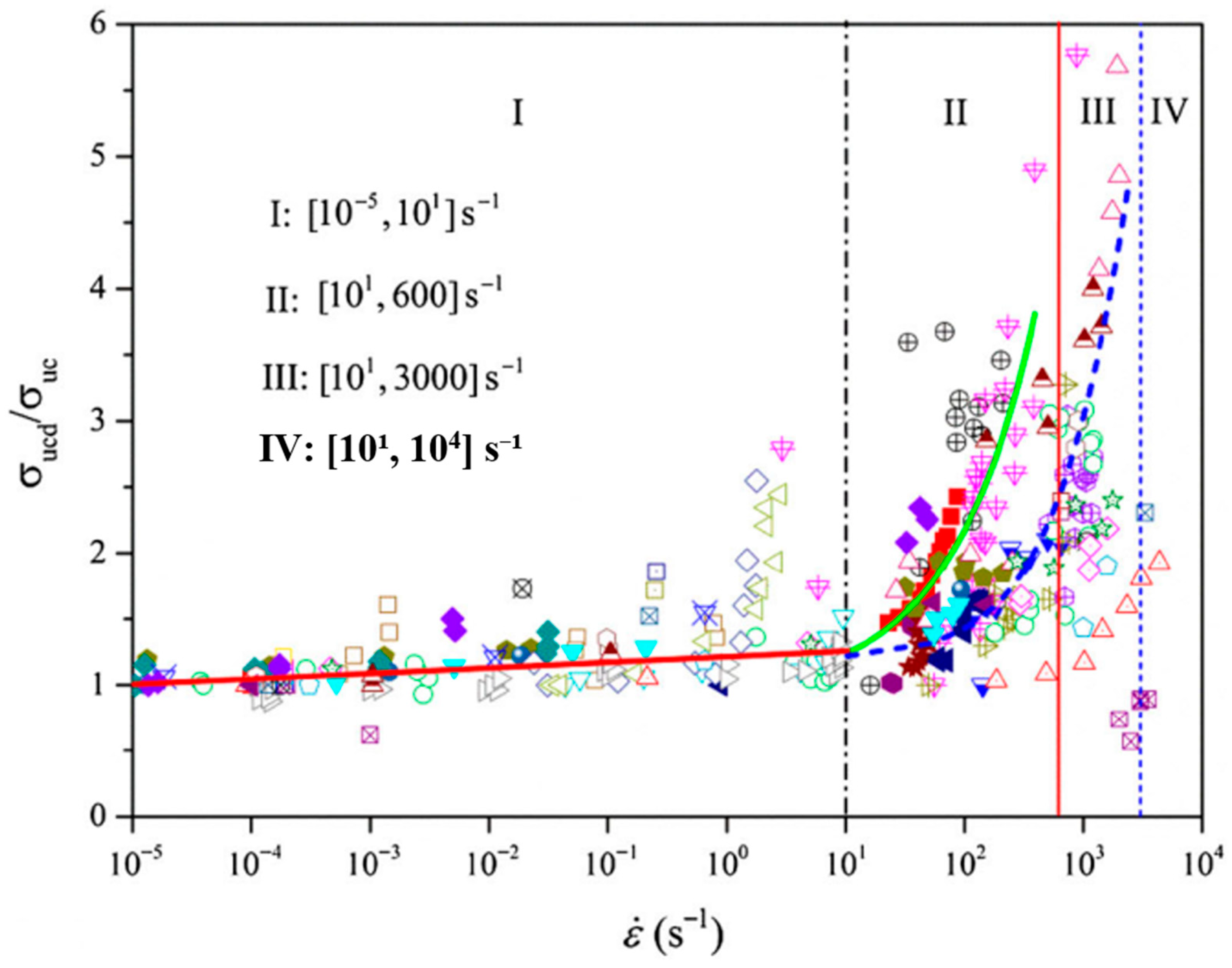
Figure 1. Relationship between rock dynamic uniaxial compressive strength and strain rate [1], in which different symbols indicate different rocks tested by various researchers cited in [1] and I–IV denote four regions of the strain rates with I classified as static region and II–IV as various dynamic regions.
Geosciences 15 00314 g001
Figure 2. Finite element modelling of dynamic Brazilian tests in SHPB with a viscoplasticity- and damage mechanics-based constitutive model conducted by Saksala et al. [62]: (i) SHPB setup, (ii) principle of modelling setup using FEM, and (iii) tensile damage distribution in the Brazilian disc.
Geosciences 15 00314 g002
Figure 3. Finite element modelling of failure mechanism of marble exposed to repeated impacts in SHPB conducted by Wang et al. [63]: (i) numerical representation of the SHPB system and (ii) comparison between the dynamic fracture processes of marbles at the impact velocities of 9 m/s (right) and 10 m/s (left) obtained from finite element modellings and laboratory experiments.
Geosciences 15 00314 g003
Figure 4. Schematic diagram illustrating the modelling of dynamic fracture in rock blasting using FEM with the element elimination technique conducted by Saharan and Mitri [74].
Geosciences 15 00314 g004
Figure 5. Modelling dynamic fracture in mining production blasting using LS-DYNA [79]: (i) borehole pattern, (ii) 3D geometry model, (iii) damage distribution and (iv) fracture pattern.
Geosciences 15 00314 g005
Figure 6. Modelling dynamic fracture in a triaxial Hopkinson bar system with six bars and a rock specimen using DEM conducted by Hu et al. [92]: (i) numerical model of the triaxial Hopkinson bar system, (ii) zoomed bars along the X direction and rock sample with 4 lateral servo walls, and fracture modes of rocks under uniaxial (iii), biaxial (iv) and triaxial (v) compression tests with an impact velocity of 20 m/s.
Geosciences 15 00314 g006
Figure 7. Modelling a single blasthole bench blasting using discontinuous deformation analysis by Mortazavi and Katsabanis [102].
Geosciences 15 00314 g007
Figure 8. Modelling rock blasting using a hybrid stress blasting model (HSBM) based on DEM by Onederra et al. [107]: (i) numerical model of FLAC zones and lattice nodes, which are connected together with springs and dashpot elements in parallel, (ii) isometric view of breakage and damage, (iii) slice section at charge mid-point perpendicular to borehole, and (iv) slice section along the axis of borehole.
Geosciences 15 00314 g008
Figure 9. Modelling rock dynamic fracture in SHPB-based dynamic BTS tests using HOSS, an FDEM code, by Rougier et al. [112].
Geosciences 15 00314 g009
Figure 10. Modelling rock dynamic fracture in SHPB-based dynamic UCS tests using HFDEM by Fukuda et al. [139]: (i) numerical model; (ii) activated contacts with BCAA and ACAA; (iii) axial stress wave propagations with BCAA and ACAA; and (iv) special distribution of damage variable and fracture pattern.
Geosciences 15 00314 g010
Figure 11. Modelling dynamic fracture of rocks by GPGPU-parallelized HFDEM3D [158]: (i) numerical model; and (ii) the distribution of the maximum principal stresses along the central horizontal and vertical planes of the rock.
Geosciences 15 00314 g011
Figure 12. Modelling the effects of loading rate with HFDEM: (i) relationship between apparent dynamic tensile strength and strain rate from the HFDEM simulation and laboratory experiments of dynamic spalling tests [180], and (ii) dynamic stress–strain relationships from the HFDEM simulations and laboratory experiments of the dynamic compression tests of roughly jointed rock specimens [181].
Geosciences 15 00314 g012
Figure 13. Modelling stress wave propagation, reflection and absorbing as well as resultant fracture pattern: (i) stress wave propagation, reflection and absorbing in Case 1 with absorbing boundary and Case 2 with reflective boundary [133], and (ii) comparison of stress wave-resultant different fracture patterns at three slices [158].
Geosciences 15 00314 g013
Figure 14. Modelling rock dynamic fracture process by ring blast with consecutive detonations of multiple long boreholes, in which the range of minor principal stress (PS3) is from 0 MPa to 500 MPa and that of damage is from 0 to 1.
Geosciences 15 00314 g014
Figure 15. Modelling the dynamic fracture of rocks under multiaxial coupled static and dynamic loads in the triaxial Hopkinson bar tests using HFDEM [178]: (i) modelled wave propagation in the bars of the dynamic TC test, (ii) comparison of modelled and experimental wave propagation in the dynamic TC test, and (iii) modelled stress distribution and progressive rock fracture process during the dynamic UC and BC tests.
Geosciences 15 00314 g015
Figure 16. Modelling rock dynamic fracturing process and fragmentation by contour blasting during deep tunnelling under high in-situ stresses (Modified after [148]).
Geosciences 15 00314 g016
Figure 17. Fracture pattern of heterogeneous rocks modelled with grain-based HFDEM [177]: (i) location of the cross-section in 3D view, (ii) 2D cross-section and (iii) zoomed 2D cross-section.
Geosciences 15 00314 g017
Figure 18. Grain-based modelling of the dynamic fracture of heterogeneous rocks during dynamic shear tests in the triaxial SPHB testing system.
Geosciences 15 00314 g018
Figure 19. Effect of pre-existing defects on the dynamic fracturing process of rock mass induced by destress blasting in deep underground sites with anisotropic in-situ stresses of 50 MPa and 100 MPa in the horizontal and vertical directions, respectively [150].
Geosciences 15 00314 g019
Figure 20. Modelling the particle size distribution resultant from rock dynamic fracturing (modified after [178]): (i) original assembly of tetrahedral elements (Ti) and cohesive elements (Ci) in intact rock with all cohesive elements in intact/softening state, (ii) new assembly of tetrahedral elements (Ti) and cohesive elements (Ci) in fractured rock with C2, C3 and C5 still in intact or softening state while C1 and C4 in broken state showing fragment formation, and (iii) fragment size distributions obtained from the final fracture patterns of rocks under dynamic UC and BC tests shown in Figure 15.
Geosciences 15 00314 g020
Figure 21. A systematic modelling approach for the dynamic fracture of rocks by blast.
Geosciences 15 00314 g021
Table 1. Differences between rock fractures under static/quasi-static loads and impact loads.
TypesPositive Aspects Negative Aspects
Static
fracture
Fracture frequently displays distinct patterns, allowing for quite accurate predictionsFracture can take a considerable amount of time to develop
Static loads allow for a better
regulated mode of rock failure
Feasible to employ mitigation strategies to prevent or control rock fractures given the gradual nature of static loads
Insignificant to loading rates
May not completely convey the conditions that rock experiences in real-world scenarios

Fractures may have limited capacity to accommodate localized variations in rock properties or structural vulnerabilities
Dynamic fractureOffer more accurate representation of abrupt and dynamic occurrences, such as rockfall, rockburst or blasting Frequently extremely unpredictable due to the complexity of dynamic events and continuously changing interactions
Fail abruptly without any warning, which can facilitate the efficient removal or fragmentation of boulders in mining and construction
Failure process is sensitive to localized variations in rock properties
Typically sudden and unexpected

Strong loading rate-dependent
Table 2. Pros and cons of FEM, DEM and FDEM in modelling rock dynamic fracture together with representative codes and the literature.
Methods (Code and
Literature)
Positive AspectsNegative Aspects
FEMImplicit and explicit algorithms for distinct static and dynamic processes, respectivelyComplex and difficult to model granular properties and contact mechanics
ADINA
[59]

(ABAQUS)
[62,74]

(LS-DYNA)
[63,68,69,70,71,79]

(AUTODYN)
[61,75,76,77]

(XFEM)
[40,48,49]

(PFEM)
[55,56]

(RFPA)
[60,66]

(Others)
[80]
Capture complex Multiphysics behavior

Easy to be combined with other numerical techniques to solve complex problems

Inherent scale independence

Allow rapid analysis of stress concentration zones, deformation pattern and associated design implications

Easily handle material heterogeneity and geometric nonlinearity

Model the complex mechanical behavior in rock and rock mass by incorporating diverse constitutive models

Able to simultaneously simulate high strain rate, strain hardening and damage softening as well as confining pressures

Suitable for small deformation
Challenging to model discontinuous behavior and not suitable for highly jointed-blocky media

Post-processing method is needed to transfer damage to fracture/fragmentation, which is somewhat arbitrary, and hence a strong background in numerical analysis is crucial

Difficult to understand the behaviour of individual cracks

Calculation time increases exponentially with number of elements, especially in the case of implicit integration

Input limitations due to the difficulty in determining certain critical parameters
DEM Able to model complicated interactionsComputationally expensive
(PFC)
[91,92,104]
(UDEC/3DEC)
[96,103]
(DDA)
[102,105,106]
(Yade)
[93,94,95]
(HSBM)
[107]
(DFN)
[109]
(CDEM)
[110]
Easy to model jointed rock systems

Able to mimic granular flow, collision and compaction

Able to describe bulk material behavior through its microstructure

Allow large deformation and detachment of blocks
Small time step and continuous changing contact detection

Limited ability to capture high-speed impact or fluidized flows

Unclear relationship between micro- and macro-properties, which makes parameter calibration process laborious (PFC)

Crack trajectory is either predetermined or mesh dependent (UDEC/3DEC and DDA)
FDEMInherit all advantages of FEM and DEMOvercome most disadvantages of FEM and DEM but computationally expensive
(Y2D)
[111,147,155]
(ELFEN)
[116,124]
(Y-Geo)
[119,137,154]
(Solidity)
[145,151,152]
(HOSS)
[112,120,123,138,156]
(HFDEM)
[3,133,134,139,140,141,149,150,157,158]
(Irazu)
[121,132,160]
(MultiFS)
[123,171]
(Others)
[136,137]
Account for transition from continuum to discontinuum

Become pure FEM before fracturing when extrinsic cohesive zone model is adopted

Deformable, breakable and irregular-shaped discrete particles

Simpler contact calculations than DEM
Parallelization is essential for large models and 3D models

Need parameter calibrations

There is a scarcity of data concerning contact properties and fracture mechanics characteristics

Micro-cracking highly depends on the fracturing mechanism
Disclaimer/Publisher’s Note: The statements, opinions and data contained in all publications are solely those of the individual author(s) and contributor(s) and not of MDPI and/or the editor(s). MDPI and/or the editor(s) disclaim responsibility for any injury to people or property resulting from any ideas, methods, instructions or products referred to in the content.