Article

Application of the Coastal and Marine Ecological Classification Standard (CMECS) to Create Benthic Geologic Habitat Maps for Portions of Acadia National Park, Maine, USA

1
Department of Environmental Earth Science, Eastern Connecticut State University, Willimantic, CT 06226, USA
2
Graduate School of Oceanography, University of Rhode Island, Narragansett, RI 02882, USA
3
Water Resources Division, National Park Service, Fort Collins, CO 80523, USA
4
Northeast Region, National Park Service, Narragansett, RI 02882, USA
*
Author to whom correspondence should be addressed.
Geosciences 2024, 14(10), 256; https://doi.org/10.3390/geosciences14100256
Submission received: 23 July 2024 / Revised: 20 September 2024 / Accepted: 23 September 2024 / Published: 28 September 2024
(This article belongs to the Special Issue Progress in Seafloor Mapping)

Abstract

:
The Coastal and Marine Ecological Classification Standard (CMECS) was applied to four portions of Acadia National Park, USA, focusing on intertidal rocky and tidal flat habitats. Side-scan sonar coupled with multi-phase echo sounder bathymetry are the primary data sources used to map the seafloor, coupled with underwater video imagery and surface grab samples for grain size and macrofaunal analysis. The CMECS Substrate, Geoform, and Biotic components were effective in describing the study areas. However, integrating the CMECS components to define Biotopes was more challenging due to the limited number of grab samples available and because the dominant species within a given map unit is largely inconsistent. While Biotopes ultimately could not be defined in this study, working within the CMECS framework to create statistically significant biotopes revealed the complexity of these study areas that may otherwise have been overlooked. This study demonstrates the effectiveness of the CMECS classification, including the framework’s ability to be flexible in communicating information.

1. Introduction

The Federal Geographic Data Committee (FGDC) adopted The Coastal and Marine Ecological Classification Standard (CMECS) in 2012 as the national classification standard. CMECS provides a framework for organizing and describing data in marine and lacustrine environments [1]. The framework is hierarchical and is composed of two settings (biogeographic and aquatic) and four components (Geoform, Substrate, Water Column, and Biotic). The National Parks Service (NPS) funded benthic habitat mapping studies following Hurricane Sandy (October 2012) at four of its park units within the northeast region of the United States (Cape Cod National Seashore, MA; Fire Island National Seashore, NY; Gateway National Recreation Area, NJ; and Assateague Island National Seashore, MD and VA). One omission of this prior work was the inclusion of a park unit characterized by rocky intertidal and shallow sub-tidal habitats. The primary objective of this project is to provide the NPS with a regional CMECS template for describing rocky oceanic and estuarine habitats for the northeastern US based on the acquisition and analysis of new data from Acadia National Park (ACAD), ME (Figure 1). This study applied methods similar to those used in the previous four-park studies to collect new geophysical data using acoustic sonar, underwater video data, and benthic biology and grain-size data from grab samples.
The results support NPS in making scientifically-sound management decisions for ACAD (and other parks), improve NPS expectations and requirements for future mapping endeavors, and contribute to the scientific field of submerged habitat mapping. The use of CMECS supplies the opportunity to generate additional examples demonstrating the application and value of the framework. This study is also valuable in that it represents the first mapping efforts for most of these survey areas. Previous mapping in the region represents seminal work on the Gulf of Maine geologic habitats for the inner continental shelf at broader scales [2,3]. State-wide maps, interpreted from 1960 aerial imagery [4], provide units analogous to the CMECS Geoform component, which have subsequently been digitized [5,6]. Other, more recent work has been focused on using the Bathymetric and Reflectivity-Based Segments (BRESS) tool [7] to delineate CMECS Geoforms throughout the Gulf of Maine [8]. The mapping work presented here improves on previous work by providing high-resolution full-coverage side-scan sonar in shallow water and near-shore environments coupled with detailed ground-truth data. The detail of the mapping in this study allows for a greatly improved understanding of the complexity of these near-shore habitats.

1.1. Geologic Setting of the Study Areas

The four field areas selected within Acadia National Park (ACAD) balanced accessibility (i.e., proximity to a boat ramp, navigable at high tide) with a range of representative habitats (Figure 1). The mapping areas included Compass Harbor, located 2 km south of Bar Harbor; Frazer Creek, located along the western side of Schoodic Point; Ship Harbor, 3 km east of Bass Harbor; and Thompson Island, located at the northern end of Mount Desert Island. Compass Harbor, Ship Harbor, and Fazer Creek are dominated by rocky intertidal shorelines (both bedrock and boulders) with sand and/or gravel sediment sheets. Thompson Island provides representative habitats for intertidal and shallow subtidal mud flats. The sites vary in water depth and relative wave energy. Bedrock geology also varies between the four sites and was mapped on a series of Maine Geological Survey Maps at various scales [9,10,11,12]. Compass Harbor is composed of Silurian-aged Gabbro. Silurian-Ordovician aged Bar Harbor formation, a foliated (layered) metamorphic rock [13], also crops out. Frazer Creek is underlain entirely by Devonian-aged granite [14]. Ship Harbor straddles a geologic contact; the inner harbor lies within the Devonian Seawall Granite; the outer portion is composed of the Silurian-aged Rhyolitic deposits as part of the Cranberry Island Volcanic Series [13]. Thompson Island is underlain entirely by the Cambrian Ellsworth Schist [13].
Mount Desert Island (MDI) and the adjacent Maine coastline had a complicated geologic history over the last two million years. The area was covered by the advancing and retreating Laurentide Ice Sheet multiple times, the most recent being during the Late Wisconsinan [15]. Moraines deposited along Jordan Pond in the southern to central portion of MDI have been dated to ~15,200 years before the present, so portions of ACAD were ice-covered at least until this time [16]. The surficial (largely glacial) deposits of the four sites vary. The Compass Harbor and Thompson Island shorelines, while mapped as a rock outcrop, are overlain by the Presumpscot Formation, a fine-grained marine mud. Ship Harbor, while also surrounded largely by rock outcrop, is overlain in part by Presumpscot Formation as well as Pleistocene and modern marine shoreline deposits [17]. These are most notable at the entrance to the inlet, where two gravelly spits extend into Ship Harbor on each side of the inlet channel. Frazer Creek, where the shoreline is not exposed bedrock, is overlain by glacial till deposits [18]. The region was isostatically depressed during deglaciation, and much of coastal Maine was inundated by marine water before the sea level fell and then rose to the present during the Holocene [19]. Portions of ACAD < 70 m above sea level were inundated by marine water during deglaciation, and this transgression is responsible for the thin layer of gravel and sand (often with boulders) common throughout the study areas [17].
The tidal range at the National Oceanographic and Atmospheric Administration (NOAA) tide gauge 8413320 located in Bar Harbor is 3.5 m (11.5 ft) [20], which falls under the high mesotidal in the classification of Hayes [21] and would be considered “moderately tidal” using the CMECS Tidal Regime modifier [1]. The tidal range appears to be similar at all four locations, although the amplitude appears to be restricted somewhat inside Ship Harbor as a result of the narrow tidal inlet. Wave energy can only be described qualitatively and is considered relatively low at Thompson Island, inside Ship Harbor, and at the more protected portions of the Frazer Creek study area. Wave energy is higher in Compass Harbor and the outer portions of Frazer Creek, which are both located along the shoreline of Frenchman Bay. Outer Ship Harbor, with essentially an unlimited fetch for storm waves from the southeast, represents the highest wave energy of the four sites. Thompson Island and the inner portions of Frazer Creek would be classified as tide-dominated, while Compass Harbor and the outer portions of Frazer Creek and Ship Harbor would be considered mixed-energy, wave-dominated [21].

1.2. Mapping Benthic Geologic Habitats and Biotopes Using CMECS

Benthic (or seafloor) habitats are spatially recognizable areas with physical, chemical, and/or biological characteristics that differ from surrounding areas [22]. A benthic geologic habitat or depositional environment is a spatially recognizable area with geologic characteristics that are distinctly different from surrounding areas [23]. This study applies a common approach to defining benthic geologic habitats using acoustic side-scan sonar validated by ground-truth data. For example, the methodology is similar to previous work performed within NPS units [24,25,26,27]. Side-scan records are interpreted by the texture and intensity of the returning acoustic signal (backscatter). Spatially recognizable areas of the seafloor with different backscatter patterns represent side-scan sonar facies. In general, the harder or denser the seafloor, the stronger the return signal and the darker the side-scan sonar record (using an inverse color scheme). Boulder and cobble fields appear darker in the side-scan record, whereas mudflats appear lighter, and sandy sediment appears more in the middle of the color scale. The side-scan record serves as the foundational data for defining polygons that represent facies; the interpretation of the facies is refined using ground-truth data. Ground-truth data in this study took the form of underwater video-imagery, aerial imagery, bathymetry, and surficial sediment samples, though other options also include sediment-profile images and sediment core data. The resulting polygons are then interpreted into geologic habitats, which can be accomplished using the CMECS classification system. CMECS includes the Substrate Component, which describes the grain size of the sediment, and the Geoform Component, which focuses on the geomorphic and structural characteristics of the seafloor [1]. These CMECS Substrate and Geoform layers are intersected to produce polygons that describe the geologic habitats using a combination of morphology and sediment texture.
This study utilizes a top-down mapping approach, e.g., [28,29,30,31], to define biotopes (or benthic habitats), following the presumption that biological communities have distinct relationships with their geologic environments or geomorphic features. Within the CMECS framework, biotopes are intended to capture ecologically meaningful relationships between biological species or communities and their physical environment. The process for developing Biotopes in this study was to integrate the benthic geologic habitats with the Biotic Community, the lowest hierarchical level of the Biotic Component. Biotic Communities are named after the dominant species within the macrofaunal community (for a given sample or grouping of samples), though the term “community” reiterates the recognition that other species are also present. Biotopes are considered preliminary until the biotic–abiotic relationships identified can be repeatedly demonstrated [1].

2. Materials and Methods

All data collection was vessel-based using an 8.5 m (28 ft) pontoon vessel with a draft of less than 0.5 m (1.6 ft) customized for shallow water surveying. Surveys extended from intertidal to shallow subtidal environments, which required conducting surveys at high tide. The primary data for this project are side-scan sonar and bathymetry acquired with an EdgeTech (West Wareham, MA, USA)6205 Multi-Phase Echo Sounder (MPES) system, along with ground-truth data in the form of underwater video and sediment grab samples. With respect to data access and preservation, final data products and maps will be stewarded on the NPS Integrated Resource Management Applications (IRMA) Portal. Raw sonar data will be submitted to NOAA NCEI for archive and public access. Underwater videos were stored as *.mp4 files and were then uploaded to YouTube (See Supplemental Table S1) for ease of sharing. Appropriate metadata will accompany all files.

2.1. Geophysical Data Collection and Processing

2.1.1. Survey Design

Geophysical surveys were conducted using a fixed, bow-mounted EdgeTech (West Wareham, MA, USA) 6205 Multi-Phase Echo Sounder (MPES) system with dual-frequency side-scan (550 kHz and 1600 kHz), which simultaneously acquires co-located side-scan and bathymetry data. The system is optimized for shallow water surveying, with the sonar mounted to the bow of the vessel in front of the pontoons, allowing for increased survey efficiency. The offset between the sonar and the vessel was maintained for all study sites. All survey components (GPS antennas, sonar, internal measurement unit) were fixed throughout the survey and offsets were applied in the software to account for the position of the sonar. The survey was planned in Hypack software and designed to collect full-coverage side-scan data (i.e., 100% coverage with 20–30% overlap) and partial coverage bathymetry (which has a substantially reduced swath width due to the shallow water depths). The survey was composed of parallel track lines with line spacing of 35–40 m (115–130 ft) and a side-scan sonar swath range of 50 m (165 ft) to allow sufficient overlap with adjacent lines. The survey design was adjusted on the fly to account for areas that were not navigable. Survey speeds were maintained <2 m s−1 (4 kts).

2.1.2. Navigation and Positioning Systems

An Applanix (Trimble) POS MV inertial measurement unit system was used during the acquisition for positional data and also to correct vessel motion (pitch, roll, heave). This was coupled with Hypack V2015 navigation software to accurately locate the vessel and geophysical sensors during the data acquisition program. The manufacturer’s stated horizontal position accuracy is 0.2 to 2 m, with a heading accuracy of 0.02 degrees. While not quantified, the vertical uncertainty of the bathymetry is thought to be <0.5 m based on the alignment of adjacent bathymetric survey lines, co-located features, and the limited RTK-GPS data collected.

2.1.3. Side-Scan Sonar Data Processing

Each sonar file was exported individually from the field collection software as Extensible Triton Format (*.XTF) files after completion of the field effort. The *.XTF files were imported into Chesapeake Technologies (Mountain View, CA, USA) SonarWiz Software (v. 6.0). The following general processing sequence was completed for the files within the dataset.
  • Navigation check on each file (including offset and layback applied), smoothing and editing if necessary;
  • Bottom tracking of each individual sonar file;
  • Application of automatic and time-varied gain curves to normalize the data across the full sweep range and over the duration of the field program. Slant range correction as applied, and gain was adjusted as needed to account for seafloor slope;
  • Draft mosaic generated to check gain settings, bottom tracking, image quality, and resolution;
  • Manual editing of applied functions as necessary;
  • Export of the sonar mosaic;
  • Export of individual sonar files as geo-referenced TIF images;
  • Export of geo-referenced TIF images for each survey area for import and presentation in ArcMap GIS software (ESRI).

2.1.4. Bathymetry Data Processing

The bathymetry data were processed using Oceanic Imaging Consultants (Honolulu, HI, USA) (OIC) CleanSweep software v.3.9.0. Bathymetric data processing followed standard techniques of first correcting for tidal variation during data acquisition using the NOAA tide gauge 8413320, Bar Harbor, ME tide gauge [32]. The water level elevation from the Bar Harbor gauge was compared to Real-Time Kinematic (RTK) GPS measurements conducted during the geophysical survey at Thompson Island and Frazer Creek (GPS malfunctions at Compass Harbor and Ship Harbor limited checks at these locations). The good agreement between the RTK-GPS and tide-gauge data suggests that the gauge data represent a good estimate of the water level at the survey sites and are suitable to use for correcting the bathymetric data. One exception is inside the basin at Ship Harbor, where the inlet appears to limit the tidal exchange and reduce the tidal range, which led to an overcorrection of the tidal data in this area. Additionally, the processing accounted for vessel motion, draft, and sonar mount angle. Filters were then applied to remove outlier soundings. The resulting mosaic presents the water depths of the survey areas at a pixel resolution of 20 cm. The bathymetric data were binned into CMECS benthic depth zones (Intertidal, 0 to 5 m, and >5 m), and an added depth range (0 to 1 m) was included to better highlight shallow intertidal features following the approach used within the Cape Cod National Seashore study [33].

2.2. Ground-Truth Data Collection and Processing

The ground-truth surveys involved the collection of surficial benthic grab samples using a Wildco Petite Ponar grab sampler coupled with underwater video imagery using either a GoPro Silver 3 or a GoPro Hero 5 camera. The GoPro was mounted above the grab sampler for co-located datasets at 45 sample sites. The position of the samples was recorded using a Garmin GPSMAP76 handheld chart plotting GPS with a reported accuracy of <3 m. Coupled with the shallow water and limited layback between the camera/sampler and the GPS, the positional accuracy of the videos and sediment samples is likely <10 m. In addition, 14 drift videos were collected by mounting a GoPro to a custom build PVC sled that is deployed and allowed to drift along the seafloor. The starting and ending position of each drift was recorded. The sample and video locations were chosen in the field at the completion of the geophysical survey to cover both a geographic spread within the site and to capture a variety of geologic habitats. Replicate sediment samples were not collected; however, the grab sample and video datasets help provide a comprehensive understanding of the study areas, as they capture geological and biological community characteristics at various spatial scales and resolutions.
The underwater video footage required minimal processing. For each video, extraneous footage at the beginning and end was removed, and title slides and end credits were added. The videos were exported in a 1080 DPI HD *.mp4 format. Representative screen captures were taken from each underwater video. These images were adjusted in Adobe Photoshop to improve the clarity and utility of the images. Processing for each image was unique; however, in general, images were adjusted for white balance to correct for the green tint in the water column, and the dehaze tool was used to improve the clarity.
The benthic grab samples were transferred to a sealed bucket after collection for transport back to the field station. The volume of each grab sample was recorded. A small (<50 mL) sub-sample from each bucket was then collected to analyze the grain size of the sediment. Sediment properties of the sub-sample were characterized using a particle size analyzer (Malvern Panalytical (Westborough, MA, USA) Malvern Mastersizer 2000E), which generated the weight percent of each particle size fraction (e.g., silt, fine sand, coarse sand, etc.) according to the Wentworth classification system [34]. The percentage cover of gravel, as well as the presence of shells, macroalgae, or other features, was estimated from the underwater video. The remaining grab sample was then wet-sieved through a 0.5 mm mesh for taxonomic analysis of benthic macrofauna. Captured macrofauna were retained and preserved in an ethanol solution. Processing was undertaken by counting and identifying individuals to the lowest possible taxonomic level (species or genus).

2.3. Interpretation of CMECS Components

2.3.1. Defining Benthic Geologic Habitats

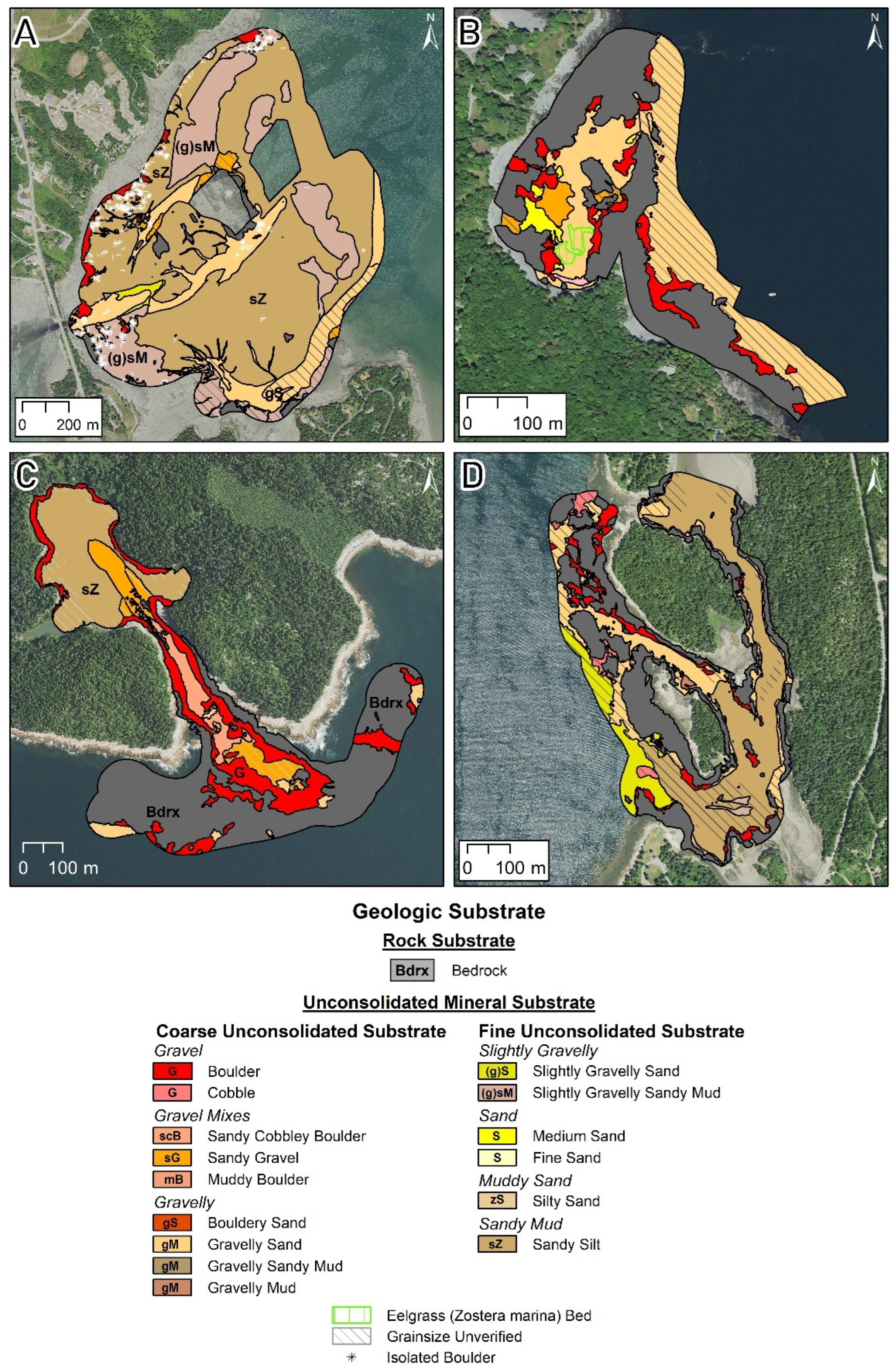
The geophysical and ground-truth data were classified using two components of the CMECS classification system. The surface sediment characteristics were described using the Substrate Component, which defines the dominant sediment type of the seafloor [1]. The extent of units within the Substrate Component was mapped primarily based on expert interpretation of the geologic facies visible in the side-scan sonar imagery. Sediment grain size, underwater video imagery, and bathymetry collected in this study, as well as digital orthophotographs and aerial imagery in Google Earth, were used to aid in the verification and interpretation of the geologic facies, particularly when there was a gradual transition zone, rather than a sharp boundary, between facies. Where grain size for a map unit is inferred, the unit is overlain by a hatched pattern. Future sampling could refine some of these interpretations.
The Geoform Component describes the geological structure and geomorphology of an area using a two-level approach [1]. While CMECS explicitly defines mapping scales associated with the different levels within the hierarchy, in general, “level 1” defines large-scale geologic features (>1 sq km), and “level 2” indicates small-scale surficial features. Given the small size of the four study areas within ACAD, all of the units interpreted should be considered “level 2”, even if some of the units are classified using “level 1” terms within CMECS (i.e., Boulder fields). The Geoform Component was interpreted largely on bathymetric data, although areas of rock outcrop and boulder fields were based on the substrate layer and interpreted from the side-scan sonar mosaic. The Geoform and Substrate Components were combined to supply information on the benthic geologic habitats of the seafloor. This was carried out using the intersect tool within ESRI ArcMap 10.6 geographic information software. The resulting polygons describe the geomorphology and sediment characteristics (i.e., Tidal Flat–Sandy Mud). This approach follows a similar process used in other previous projects both within and outside of the NPS system [35].

2.3.2. Defining Biotopes

Biotope Classification Approach

The term “biotope” within the CMECS framework is used to describe benthic habitats and is specific in that it integrates biotic and abiotic data intended to provide a more ecologically meaningful understanding of a given area. This study aimed to follow the top-down mapping approach used for a previous study conducted at Fire Island National Seashore [35]. The first step is to delineate the benthic geologic habitat map units based on the CMECS Substrate and Geoform Components to serve as the basis for the biotope analysis (refer to Section 2.3.1). Statistical analyses (described below in the Statistical Approach section) are conducted to identify map units that contain significantly distinct macrofaunal communities. In this process, factors are assessed collectively and independently to investigate relationships between macrofaunal communities and components of their associated abiotic environment. The factors in this study are the Substrate and Geoform CMECS components, along with relative water depth. The factor(s) showing the strongest statistically significant relationships with the macrofaunal communities then represent the abiotic classification of the map units. The biotic classification is represented by the Biotic Community, the lowest hierarchical level of the Biotic Component, which is defined according to the dominant macrofaunal species, i.e., the species with the highest abundance (counts of individuals) combined across all grab samples within each given map unit. Note that while the Biotic Community is named by the dominant species, the term “community” reiterates the recognition that other species are also present. The resulting classification output is a color-coded map illustrating the distribution and extent of various biotopes defined according to the Geoform, Substrate, and Biotic Components of the CMECS framework, as well as an associated attribute Table.

Statistical Approach

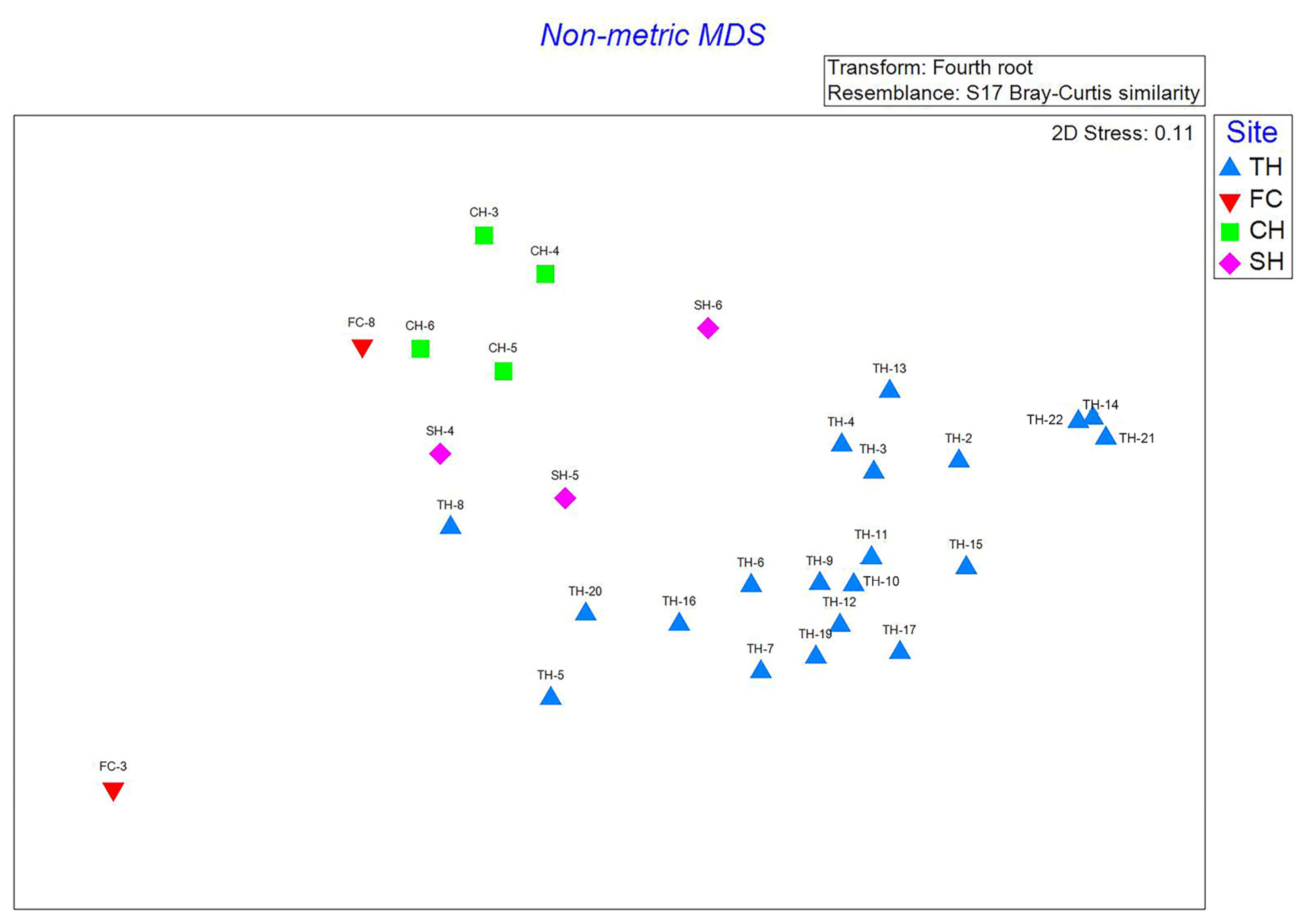
This study utilizes nonparametric statistical analyses, a common approach for ecological studies investigating multivariate data, such as species and abundance data organized by sample site [36,37,38]. Other benthic mapping studies that have used a nonparametric statistical analysis approach include [24,25,26,27,28,29,31,33,35]. The statistical software package PRIMER v7 [36,37,38] was used for all statistical analyses. To prepare the taxonomic data for statistical analysis, species abundances were 4th root transformed, and the Bray–Curtis similarity index was used to create a matrix of sample site-similarity. A non-metric multidimensional scaling (nMDS) ordination plot was used to investigate macrofaunal community composition among the sample sites across the four study areas. The nMDS plot displays the level of similarity among samples in a dataset, which are represented as points in 2- or 3-dimensional space. The relative distance of samples from one another on the plot indicates similarity, with shorter distances signifying higher degrees of similarity. In this study, each point on the plot represents the benthic macrofaunal community composition at one sample site. Points that are closer together on the plot represent sites that are more similar in composition than those that are further apart. The stress value provided in the plot is an indication of the level of distortion within the ordination; the lower the stress, the better the plot represents the data. The nMDS plot is used in this study to determine if the more suitable approach is to analyze and classify biotopes for the four study areas together or separately. The relationship between the macrofaunal biological communities (represented by each grab sample) and their associated benthic geologic habitat map unit classification was assessed using the multivariate statistic routines Analysis of Similarity (ANOSIM) and Similarity Percentages (SIMPER) for each study area. The ANOSIM routine was first used to test the null hypothesis that there are no differences between biological communities among user-defined groups. For this study, the user-defined groups were the Substrate Component, Geoform Component, and relative water depth. These groups were assessed individually and in combination. An ANOSIM R-value of 0 indicates that there are no differences in the macrofaunal communities across the groups, whereas a value of 1 indicates complete distinction. R values between 0 and 1 reflect an intermediate degree of the difference along the spectrum. The ANOSIM routine also provides a significance level, referred to as a p-value, that is expressed as a percentage. The generally acceptable significance level is p equal to or less than 0.05 (5%). Identifying the grouping structure with the largest statistically significant ANOSIM R-value is of greatest interest for mapping biotopes. The SIMPER routine was then used for the grouping with the highest ANOSIM R-value. SIMPER compares pairs of samples by examining the degree (as a percentage) to which each individual species contributes to the within-group similarity of the sample groups and reporting the average within-group percent similarity. SIMPER also reports the average percent dissimilarity of the sample groups between all pairs of samples and how each species contributes to this dissimilarity.

3. Results

3.1. Geophysical Data

3.1.1. Survey Design

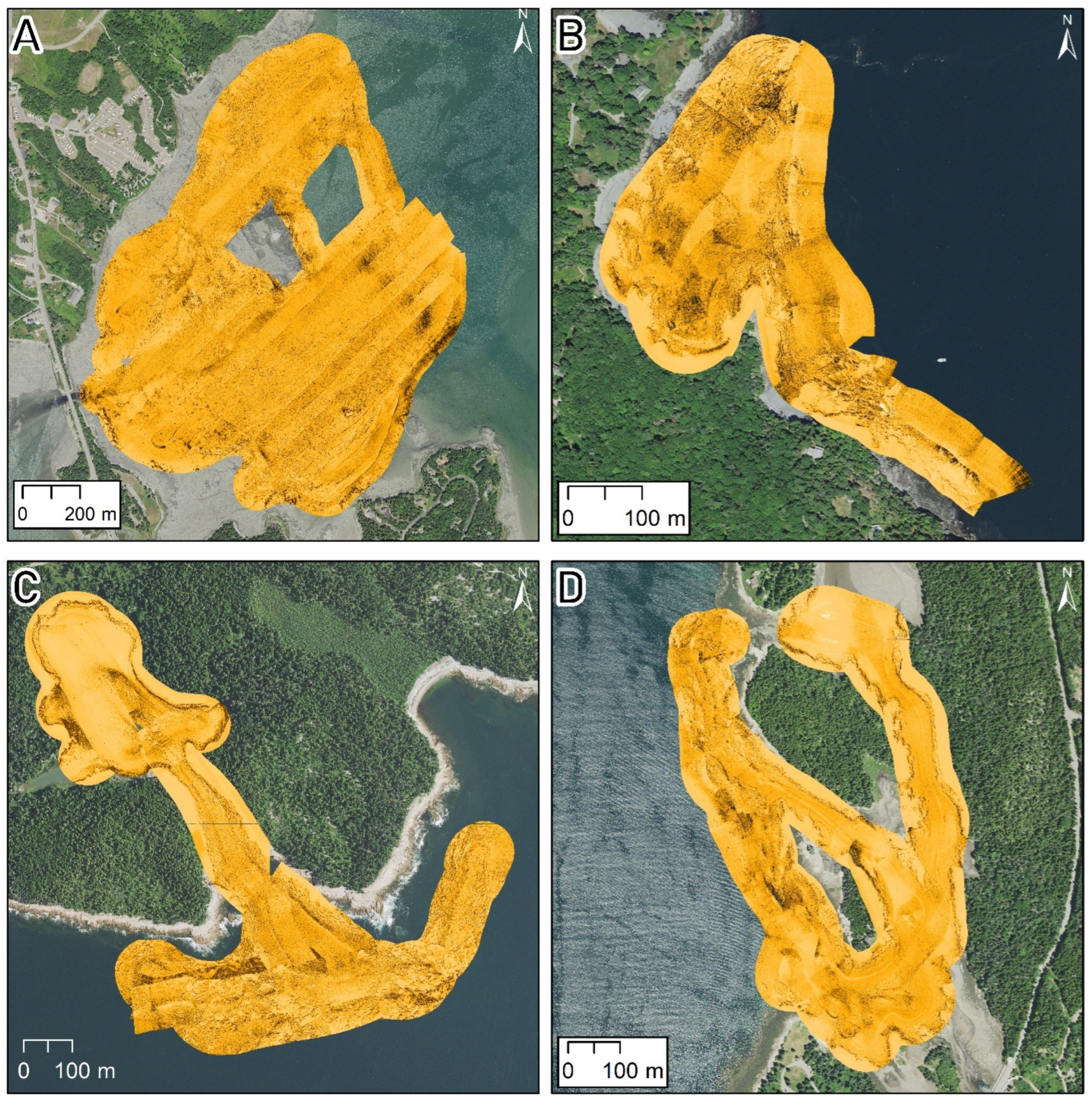
Mapping of the four field sites (Figure 2) was conducted between 19 and 24 September 2021. Given the shallow nature of the study sites and mesotidal range (3.5 m) of the study areas, surveys occurred during a 6-to-7-hour window centered around high-tide. The boat was launched, and all the equipment was mobilized and demobilized daily.

3.1.2. Side-Scan Sonar Data

A total of nearly 2.1 km2 (512 acres) of seafloor was mapped with full-coverage side-scan sonar over the four field areas (Table 1). Surveys generally covered the limit of navigable waters at high tide, and in most portions of the sites, the survey extended to the shoreline. Intertidal boulders limited the extent of the survey along the shoreline at Thompson Island (Figure 2).

3.1.3. Bathymetry Data

The bathymetric data were not full-coverage due to shallow water depths and the reduced effective swath width. The swath width for shallower areas is constrained to 4–6 times the water depth. This resulted in approximately 25% to 75% bathymetric coverage, depending on the water depth of the area. Depth ranges varied for all four sites. Outer Ship Harbor, Compass Harbor, and Frazer Creek all extended from the intertidal out to a water depth >10 m relative to MLLW. Thompson Island, which featured extensive intertidal mud flats only exceeded > 2 m water depth (relative to MLLW) along the eastern end of the study area and in several tidal channels (Figure 3). Bathymetry data within the inner portion of Ship Harbor show apparent error for the inner portions of Ship Harbor. When processing the bathymetry, applying the Bar Harbor tidal corrections here resulted in the entire cove showing as intertidal, which does not match either the aerial images of the cove or field observations of the area when observed at low tide on 21 September 2021. As a result, only the bathymetry of the outer portion of Ship Harbor (seaward of the inlet) is reported here (Figure 3). The bathymetry was binned into the CMECS littoral, shallow infralittoral, and deep infralittoral depth zones. The shallow infralittoral depth range was split into two bins (0 to −1 m and −1 m to −5 m) to better show the intertidal and shallow sub-tidal portions of the study areas following the approach used in the NPS Cape Cod National Seashore study [33].

3.2. Surface Sediment Grab Samples and Underwater Video Imagery

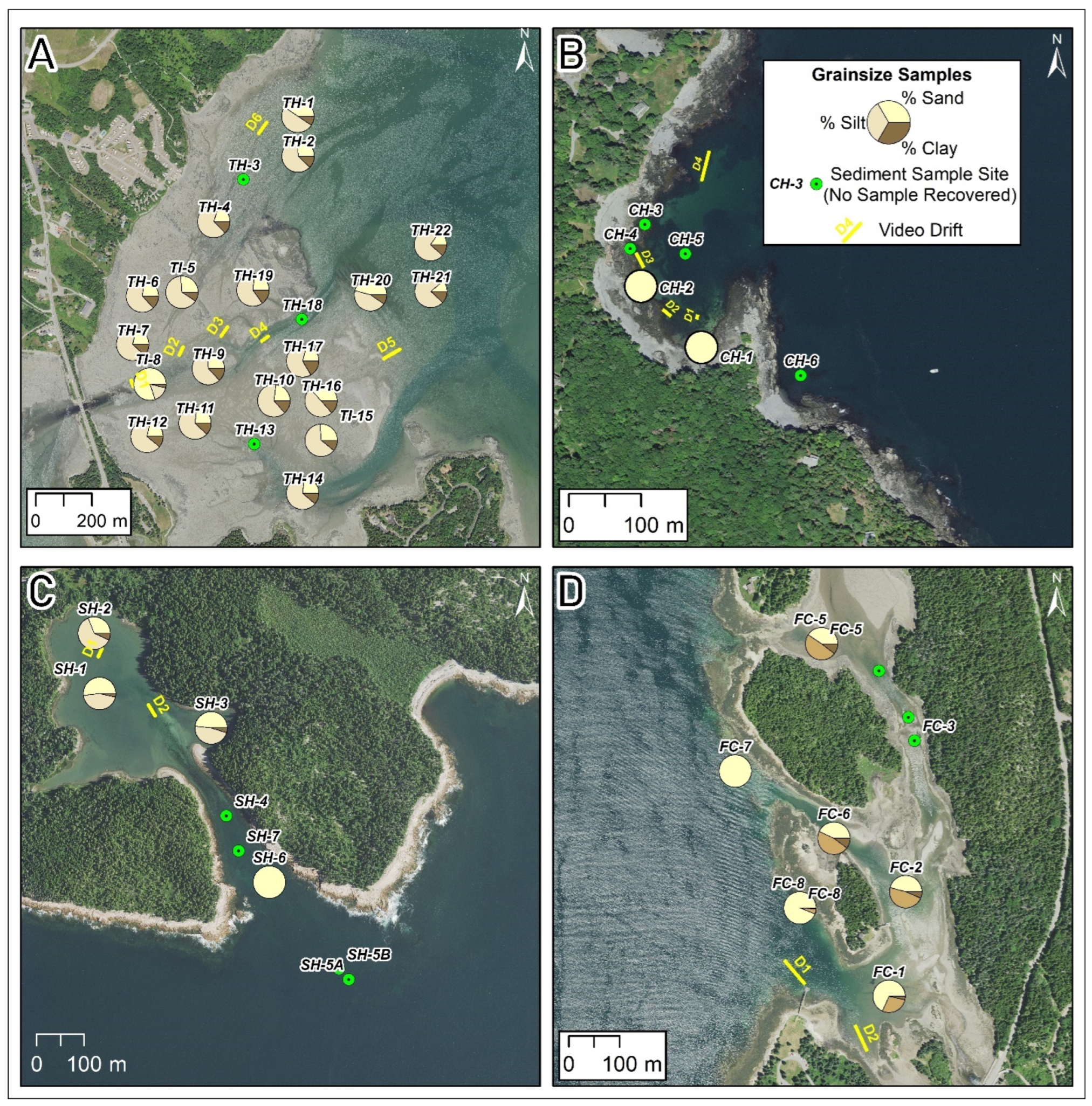
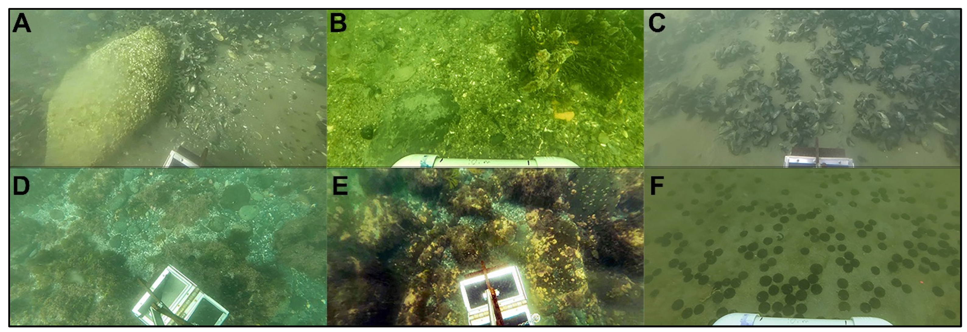
A total of 45 benthic grab samples were attempted across the four study areas (Figure 4). Sediment samples for analysis were recovered for 31 sites (Table 2). The grain size was plotted on ternary diagrams, displaying the percentage of sand relative to the ratio of silt to clay following the classification within the CMECS system. Where sediment samples were not recovered, the seafloor was largely composed of gravel or bedrock, and the characteristics of the benthic geology were determined using the underwater video. Underwater video was collected at all surface sediment grab sample locations, and an additional 14 video drifts were collected. Example images from the grab samples and video drifts are shown in Figure 5. The underwater video imagery was collected in conjunction with the surface sediment grab samples at all locations except two where the camera failed. These provided a ~1 m2 view of the seafloor (depending on water depth and visibility) around the sample location. Additional coverage of the seafloor was recorded as the sampler was lowered and recovered. This spatial scale was useful in examining the heterogeneity of the seafloor, particularly in areas of mixed sediment types. An example of this is shown in Figure 5B,D,E, where a mixture of sand, gravel, and bedrock outcrop was observed in drop camera imagery. The imagery was used to validate interpretations of the sonar and estimate the percentage of gravel/sand in these areas. The video drifts, which spanned <10 to >100 m depending on wind and tidal current velocities, recorded oblique videos that were useful for the spatial complexity (or lack thereof) of the seafloor. The drift videos were particularly useful for identifying various benthic organisms that would have been missed in sediment sampling. Examples include observing European Green Crab (Carcinus maenas) (Thompson Island and Ship Harbor), Sand Dollars (Echinarachnius parma) (Compass Harbor), and Eelgrass (Zostera marina) (Compass Harbor and Ship Harbor). Benthic macrofaunal samples were recovered at 43 sites (Table 3). However, four samples were found to contain no individuals, and an additional nine samples contained five or fewer individuals. These 13 samples were removed from further analysis. The resulting taxonomic dataset is a spreadsheet listing species (or genus) names and counts (rows) for 30 sample sites (columns). Each grab sample represents the macrofaunal biological community structure at the sample site.

3.3. Application of the CMECS Classification System

3.3.1. Substrate Component

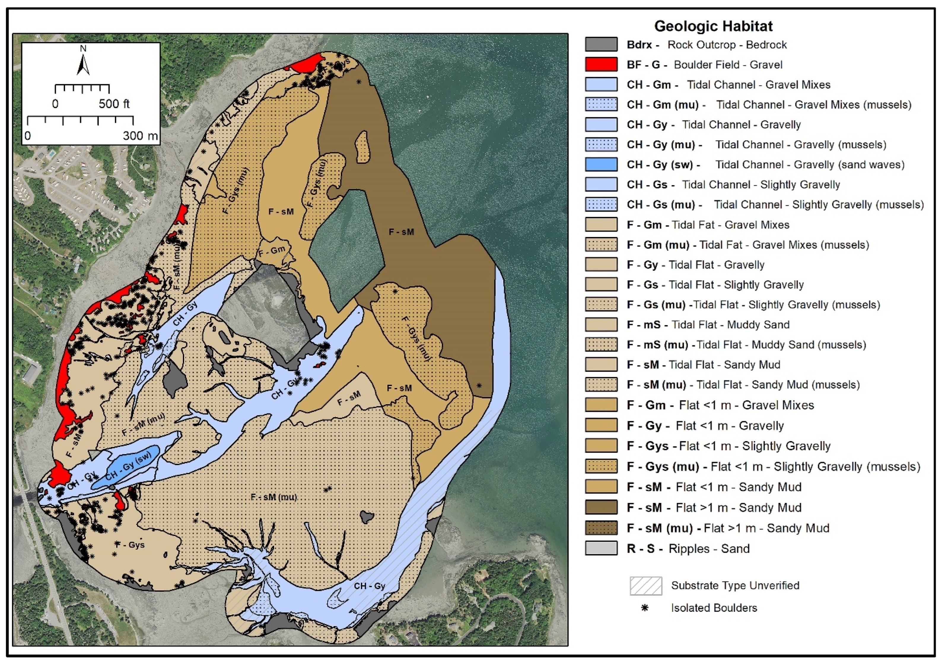
The surface sediment characteristics of the four study areas in ACAD were classified to both the Group and Subgroup levels within the CMECS classification system. Where directly sampled, the percentage of sand, silt, and clay was reported. The percentage of gravel was estimated from underwater video imagery. Areas of boulders or bedrock were not sampled, but these features were readily identifiable on the side-scan records and/or vertical aerial photographs. Isolated boulders, which occur in a portion of Thompson Island, were not included in the naming of the surrounding sandy silt map unit. The number of boulders within that unit is less than 0.01% of the mapped area (Figure 6A). The digitized side-scan sonar facies identified were then characterized using the ground-truth information. Where the grain size was not sampled or imaged directly, the sediment character was interpreted based on adjacent side-scan facies within that study area; these areas are displayed with an “unverified” hatched overlay on the interpretive maps. The extent of the unverified units was mapped using the side-scan sonar mosaic. More sampling in the future could further refine the substrate maps. Substrate units ranged from bedrock and boulders to muddy units and the results are displayed on Figure 6. The detailed summary for each study area is found in Table 4.

3.3.2. Geoform Component

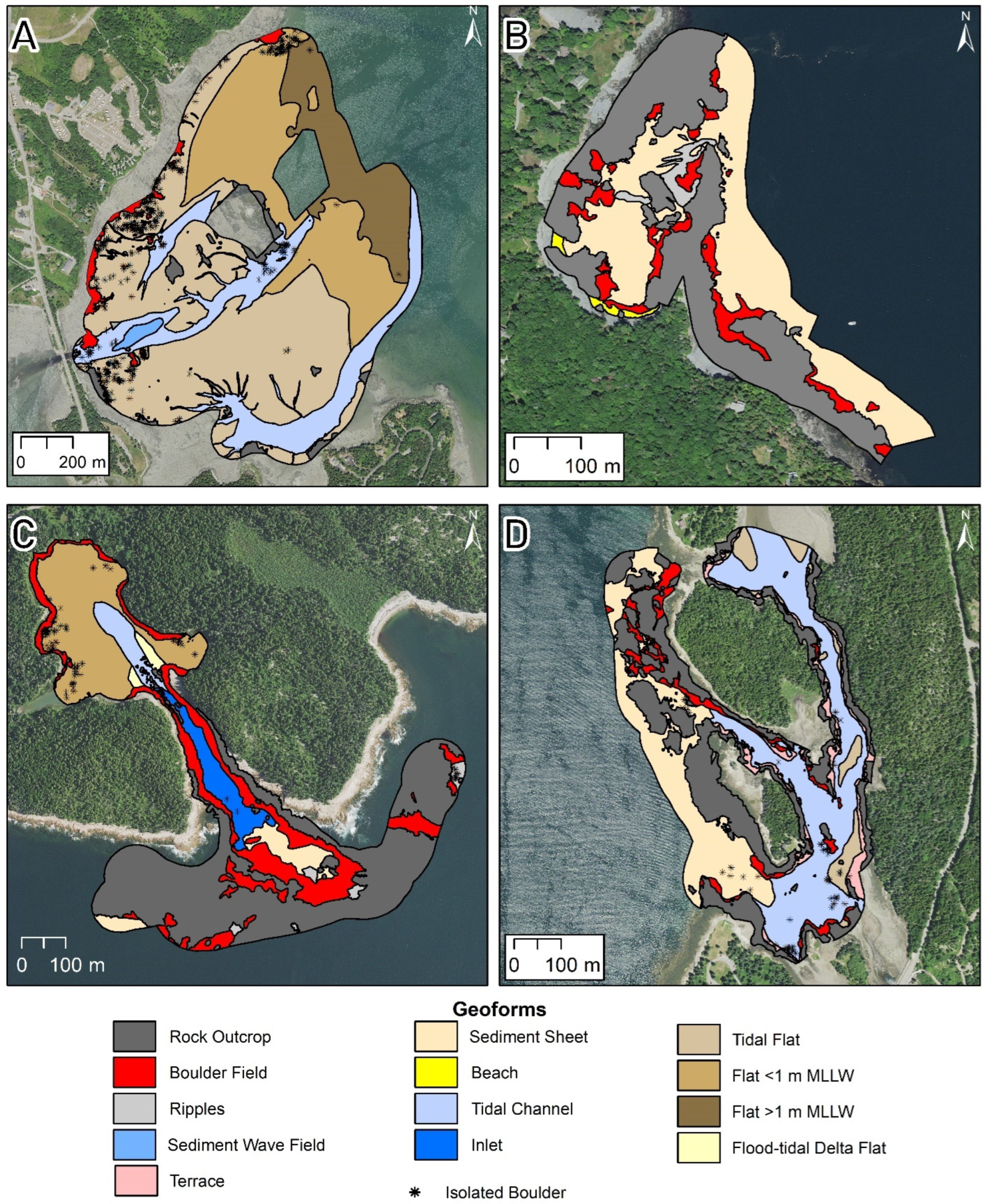
The geomorphology of the four study areas within ACAD were interpreted using the Geoform Component framework within CMECS. Given the small scale of these four areas, the units chosen all should be considered as “level 2”; however, some of these units (i.e., Boulder Field) are only described as “level 1” within the CMECS hierarchy. The mapped extent of Rock Outcrop and Boulder Fields is based on the polygons interpreted from the substrate component, derived largely from side-scan sonar. Other features (channels, flats) are interpreted using a combination of bathymetric data, side-scan sonar, and 2018 digital orthophotographs. Similar to the substrate component, rocky habitats (both Rock Outcrop and Boulder Fields) dominate three of the four study sites (Compass Harbor, Ship Harbor, Frazer Creek). Thompson Island is predominantly intertidal and shallow subtidal flats (Figure 7; Table 5).

3.3.3. Anthropogenic Geoforms

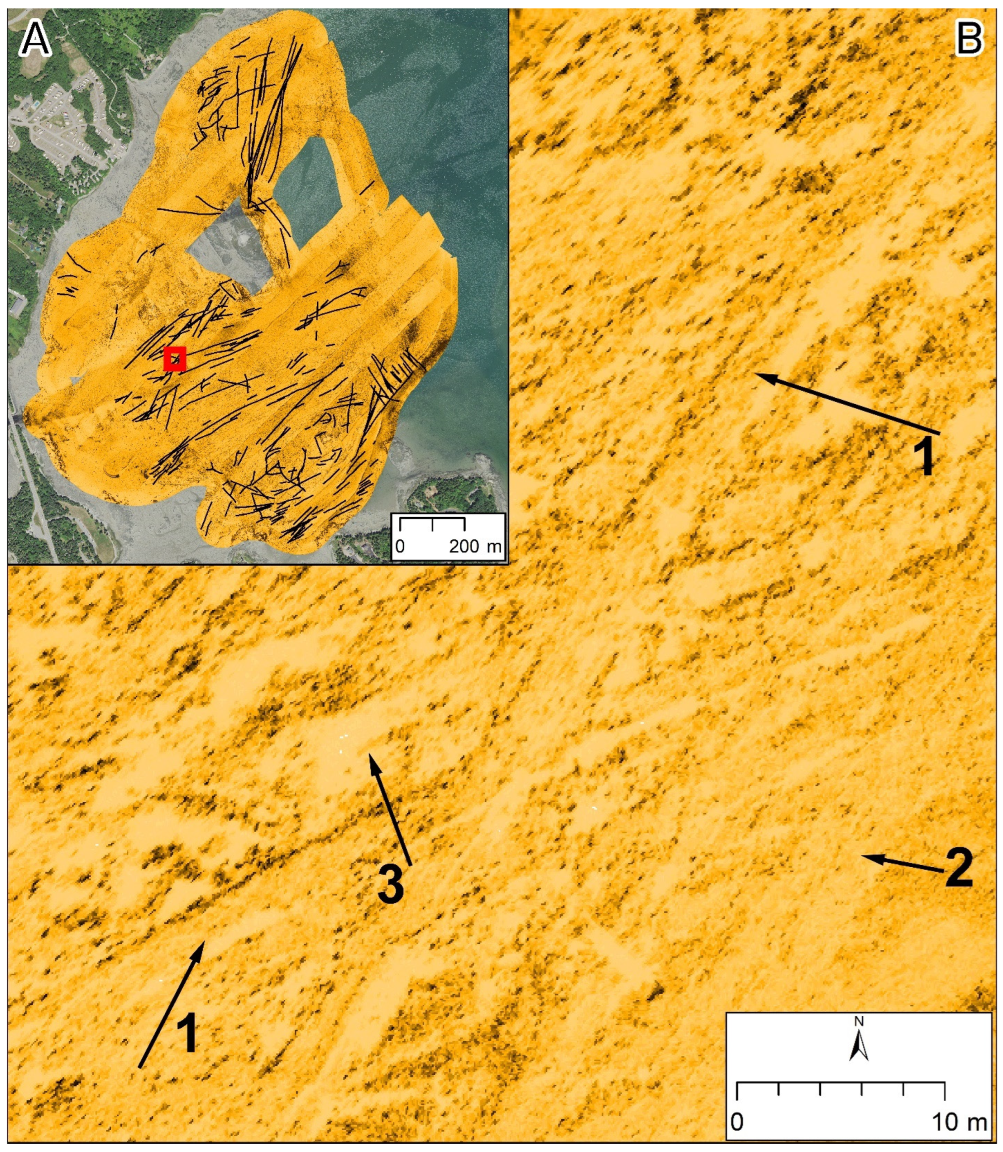
Prominent anthropogenic impacts on the seafloor were visible at Thompson Island as distinct linear furrows on the side-scan sonar mosaics and in the bathymetry. These features are interpreted to be dredge disturbances. The dredge disturbances represent a level 2 Geoform and are mapped as linear polyline features (Figure 8). Individual dredge trails are ~2 m wide and extended for 10s to >100 m in length. These dredge disturbances are interpreted to be the result of hydraulic dredges utilized for the commercial harvest of blue mussels (Mytilus edulis). A vessel harvesting mussels was observed during the field survey, with a hydraulic dredge that matches the scale of these features, providing evidence of the origin. Additionally, mussels were observed in both the surface sediment grab samples and underwater video imagery in this region. The total length of the mapped dredge trails was ~25,000 m2; however, it should be noted that this is not an exhaustive account. Many of the trails cross-cut or overlapped with other trails (Figure 8), indicating that this reported value should be considered a minimum. Applying an average width of 2 m to the features results in an impacted area of ~50,000 m2, representing 3.6% of the mapped extent, although the percentage of the seafloor impacted by dredges is likely higher.

3.4. Benthic Geologic Habitats

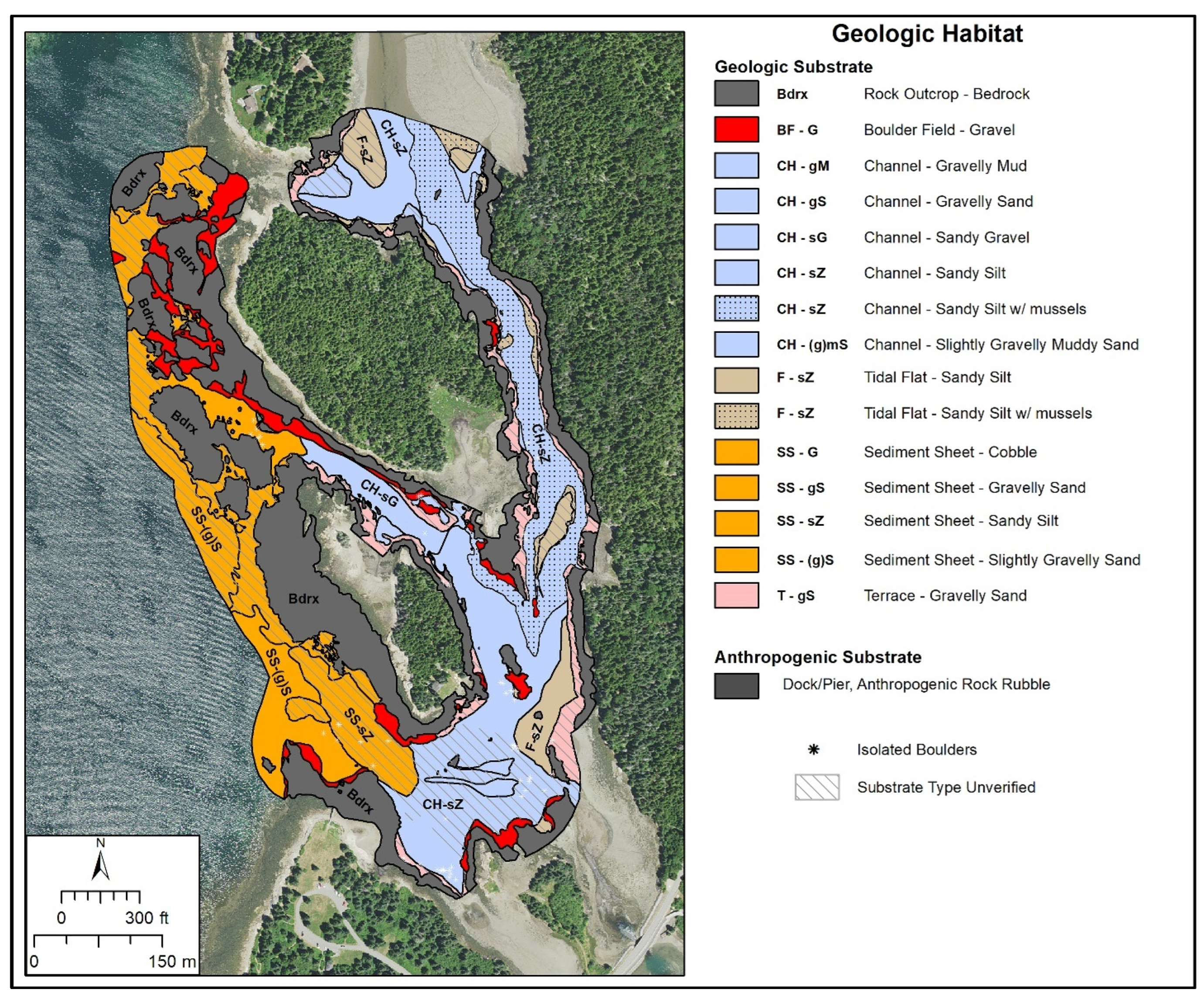
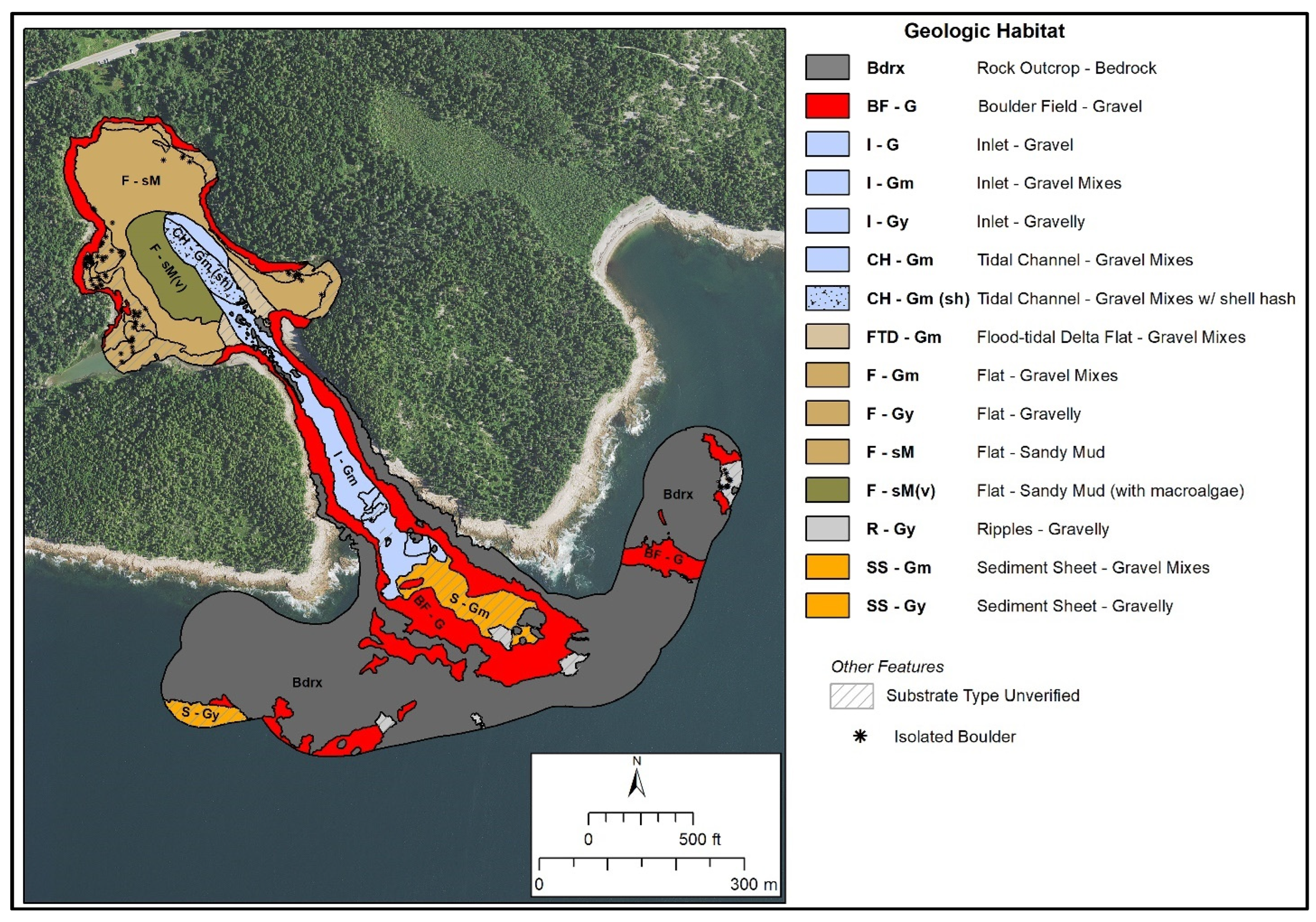
Benthic geologic habitats of the four areas combine the Geoform and Substrate components. These two data layers were intersected in ArcMap to produce a data layer that contains both the substrate and Geoform information. Mapped surface overlays (extent of drift macroalgae, eelgrass beds, shell hash/rubble, or mussel beds) were also intersected with the geologic habitats to better describe the conditions at the time of mapping. The maps shown are visually similar to the Geoform component maps; however, the resultant units are also labeled using the Substrate component layers. This integrated output facilitates easier understanding of the map, as opposed to having potentially dozens of map units of various colors for the end-user to interpret. The geologic habitat maps are labeled using an abbreviation for both the Geoform and substrate subgroup (i.e., SS − sG = Sediment Sheet − Sandy Gravel). An additional modifier (e.g., “sh” for shell hash/rubble) was added where needed to incorporate the overlays presented in the substrate components. For example, a channel (Geoform) with gravelly sediment would be labeled as “Channel, Gravelly”. Where a Geoform type was identified (i.e., Tidal Channel, Muddy Sand), these were used in the name to provide more description of the geologic habitat of that map unit.

3.4.1. Compass Harbor

Rocky habitats comprise 55% of the Compass Harbor study area (46% Bedrock–Rock Outcrop; 9% Boulder Field Gravel) (Figure 9). Much of the rest of the study area was composed of a mixture of gravelly and gravel mixes that form a sediment sheet, both within and outside of the harbor. Areas of ripples, which represent sorted bedforms or rippled scour depressions [39], cover 2.5% of the study area, mostly along the bedrock point extending across the southern half of the harbor. The bedforms here have a crest-to-crest spacing of 0.5 to 0.9 m (ripples to small dunes),. While technically a Biotic Group, a seagrass bed, was identified on the side-scan sonar imagery and confirmed with underwater video in the southern portion of the harbor. The seagrass (Eelgrass, Zostera marina) bed occurs as two patches totaling 1607 m2 (0.4 acres).

3.4.2. Frazer Creek

Rocky habitats comprise 39% (33.7% Bedrock, 5.3% Boulder Field) of the Frazer Creek study area. Outer (western) portions of the study area are interpreted to be a sediment sheet (20%), ranging from sandy silt to gravelly sediment (Figure 10). The inner (eastern) portion of the study area is dominated by channels (30%), ranging from sandy silt to sandy gravel. Mussel beds were common in the channel and were delineated as a separate habitat unit. Muddy units interpreted to be tidal flats were mapped at the northern end of the study area. Elsewhere along the shoreline and channel, coarser sediment units are interpreted as gravel terraces that formed as the glacial till mantling the bedrock outcrop eroded during marine transgression.

3.4.3. Ship Harbor

Rocky habitats dominate Ship Harbor; Rock outcrop-Bedrock cover 46% of the mapped area, and Boulder Field gravels cover 19% (Figure 11). Within the inner harbor/cove, finer-grained sediment has accumulated, although boulder outcrops are still common, particularly along the shoreline. Adjacent to the tidal channel within the inner harbor, areas showed abundant shell hash/debris, which produces a darker side-scan sonar mosaic. These shells were likely transported into the inlet via tidal currents and accumulated in the channel. Portions of the sandy mud flat were covered with drift/decayed macroalgae, which was observed in sediment samples and underwater video imagery. Within the inlet, various gravelly units were identified, which were distinguished by their side-scan facies and confirmed with underwater video imagery.

3.4.4. Thompson Island

The Thompson Island study area was dominated by Sandy Mud, which occurs as Tidal Flats (37.2%), shallow subtidal flats (<1 m MLLW) (18%), and slightly deeper (>1 m MLLW) flats (15.4%) (Figure 12). Rocky habitats (Rock Outcrop-Bedrock (2.2%) and Boulder Field Gravel (1.6%)) occupied 4% of the total mapped areas. Isolated boulders within other habitats were common, particularly along the northern and western shorelines; >400 individual boulders were mapped. Mussels were common on the tidal flats in varying densities, covering a total of 0.6 km2. These units have a stippled pattern in Figure 12.

3.5. Benthic Biotope Classification

An nMDS plot was used to determine if the more suitable approach is to analyze and classify biotopes for the four study areas together or separately. Each point on the plot represents the benthic macrofaunal community composition at one sample site, i.e., all species and their abundances recovered in one grab sample. Points that are closer together on the plot represent samples that are more similar in composition than those that are further apart. The low stress value (0.11) indicates that the plot is an acceptable representation of the data. The plot shows samples separated out according to the study area, indicating macrofaunal communities are more similar within a given study area and more distinct across study areas (Figure 13). This result supports the development of individual biotope maps for each study area, which is further confirmed after the assessment of the taxonomic dataset. It is noted that sample site FC-3 separates out to a greater degree compared to the other samples; this is attributed to the samples containing solely 40 individuals of the species Semibalanus balanoides, the common acorn barnacle, which was not recovered at any other sample site.

3.5.1. Compass Harbor, Frazer Creek, Ship Harbor

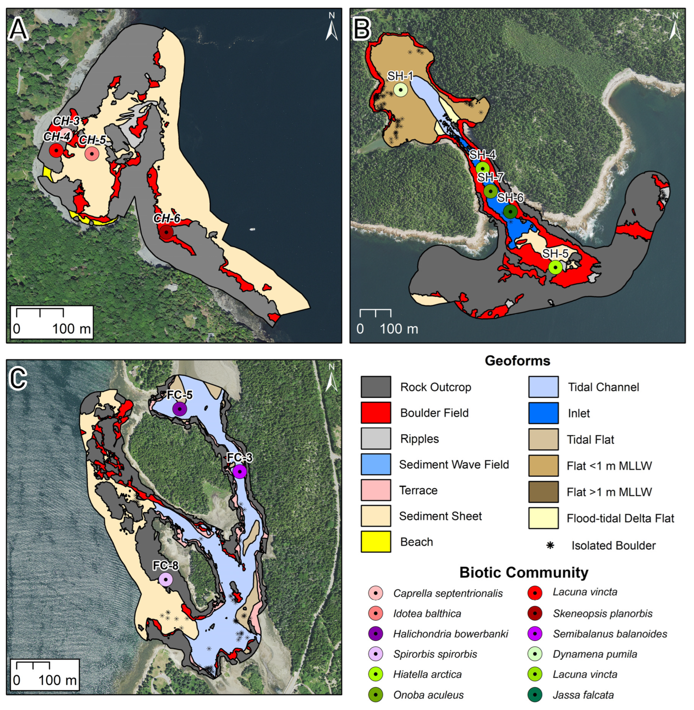
The benthic geologic habitat map units developed for all four study areas (refer to Section 3.4) were intended to serve as the map units for the biotope classification for this study. However, in three study areas, it was not possible to conduct statistical analyses or develop biotope maps due to an insufficient number of macrofaunal samples: Compass Harbor n = 4, Frazer Creek n = 2, Ship Harbor n = 3 (Table 3). Instead, the resulting biotope classification is directly associated with each grab sample. The maps for these study areas show the maps units defined by the Geoform Component level 2 classification with the geographic location of each grab sample plotted and classified according to the Biotic Component Biotic Community level (i.e., dominant species with respect to abundance). The maps (Figure 14) also illustrate that each sample within a given study area is dominated by a different species, even for samples collected within the same Geoform type, highlighting variability/uncertainty in biotic-abiotic relationships that may be present.

3.5.2. Thompson Island

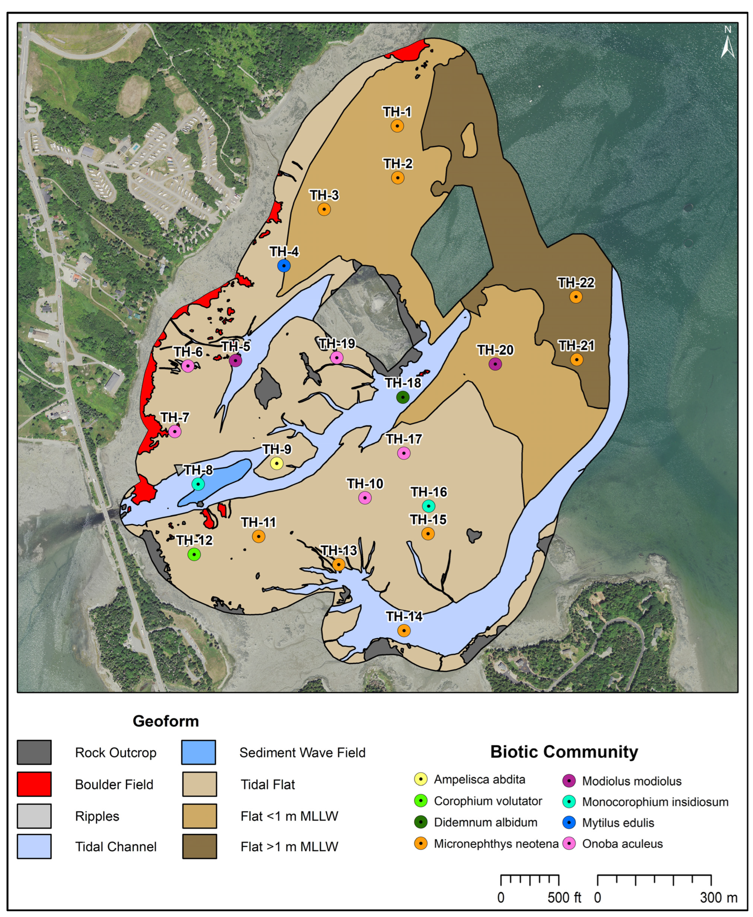
The Thompson Island study area had a sufficient number of samples (n = 21) to proceed with statistical analysis. ANOSIM found the Geoform Component (flat, channel, sediment wave field) combined with relative water depth (tidal, <1 m MLLW, >1 m MLLW) offered the strongest relationship with the biology (ANOSIM R = 0.608; p = 0.002). The five resulting map units that contained macrofaunal samples were Tidal Flat, Flat < 1 m MLLW, Flat > 1 m MLLW, Tidal Sediment Wave Field, and Channel. The ANOSIM R-value indicates there are statistically significantly distinct macrofaunal assemblages among these map units. The SIMPER routine was run on the four Geoform map units that contained more than one macrofaunal sample (Figure 15). The output shows that the average within-group similarity varies among the map units, ranging from 0% to 60.63% (Figure 15). The “Flat > 1 m MLLW” map unit reported the highest within-group similarity (60.63%) (Table 6). Further examination of the taxonomic data shows that the two samples within this map unit both have low total abundance (n = 12 at TH-21; n = 14 at TH-22), and macrofaunal community composition for both is almost exclusively Micronephthys neotena (n = 10 at TH-21; n = 13 at TH-22). The “Flat < 1 m MLLW” map unit reported a relatively low within-group similarity of 33.65%. Examination of the taxonomic data reveals there is minimal commonality across the three samples (TH-2, TH-3, TH-20) with respect to species composition and abundance. For example, TH-3 is dominated by the amphipod, Ampelisca vadorum, whereas the other samples have counts of 1 or 0. Similarly, TH-20 is dominated by the bivalve, Modiolus modiolus, and TH-2 and TH-3 are dominated by the polychaete Micronephthys neotena, while these species were not recovered in the other samples. The total abundance in each sample ranges from 32 to 69.
The “Channel” map unit reported 2.13% within-group similarity. Examination of the taxonomic data confirms that the three samples located in the Channel (TH-5, TH-14, and TH-18) share one common species, the blue mussel (Mytilus edulis), and are characteristically different. TH-5 contains 13 species and totals 699 individuals, dominated by the bivalves Modiolus modiolus (n = 412) and Mytilus edulis (n = 88). Sample site TH-14 contains two species with a total of 9 individuals (Micronephthys neotena n = 8; Ampelisca sp. n = 1), and TH-18 contains six species and seven individuals. The “Tidal Flat” map unit contained the most samples (n = 12) and reported a relatively low within-group similarity of 34.63%. The taxonomic data show some commonality across the twelve samples with respect to species composition and abundance but also exhibited high variability. Species abundance ranged from 14 to 296 per sample, and species counts ranged from 4 to 17. The twelve samples combined have 45 distinct species. The four species reported to be most responsible for the within-group similarity (Table 6) were present in 8/12 samples, demonstrating continuity across the samples. However, the abundance of these species varied across samples. For example, Onoba aculeus abundance ranged from 1 to 232 across 12 samples, with a total abundance of 607, whereas Alitta succinea was more consistent, ranging from 1–8 individuals per sample with a total abundance of 38. The remaining species were present in fewer samples: eight species were present in 4–7 samples; two species were present in three samples; six species were present in two samples, and 25 species were only present in one sample. The majority of these species also tended to be present in relatively low total abundance (>20 individuals).
Overall, the sample sites across Thompson Island exhibited a unique trend where a given site contained a relatively high abundance of one to three species, accompanied by a low abundance of other species. For example, at site TH-7, 97 individuals of the species Onoba aculeus were recovered, along with five other species containing ≤8 individuals. Site TH-20 sampling recovered 25 individuals of Modiolus modiolus along with seven other species with one individual each. Site TH-5 had 412 individuals of Modiolus modiolus, with 139 Gammarus oceanicus, 88 Mytilus edulis, 25 Streblospio benedicti, and an additional nine species containing ≤10 individuals.
CMECS defines biotopes by integrating the Biotic Component with one or more of the abiotic components. Data from this study support using the Biotic Community level of the Biotic Component, which is defined by dominant species. Therefore, confidently defining biotopes requires that at least the majority of macrofaunal samples within a given map unit have the same dominant species, as this demonstrates consistency in the linkage between macrofauna and their environment and provides confidence for assigning classifications in map units within the study area that have not been sampled directly. While the ANOSIM and SIMPER results indicate that distinct macrofaunal communities are present within the geologic habitat map units at Thompson Island, assessment of the macrofaunal taxonomic data for each sample showed that the dominant species within a given map unit is largely inconsistent. This inconsistency precludes the development of biotopes. Therefore, as with the other study areas, the resulting map for Thompson Island shows maps units defined by the Geoform Component level 2 classification with the geographic location of each grab sample plotted and classified according to the Biotic Component Biotic Community level (i.e., dominant species with respect to abundance) (Figure 15). Visual assessment of the map output further clarifies the challenge of defining biotopes. For example, there are three dominant species for the map unit “Flat < 1 m MLLW”, creating low confidence in what the dominant species might be at other locations throughout the map unit that were not sampled directly. Similarly, the grab sample in the “Tidal Channel” map unit in the northwestern portion of the study area is defined by a different dominant species than the sample in the southeastern map unit. This creates low confidence in defining the “Tide Channel” map unit that extends through the middle of the study area; this situation could be resolved with additional sampling and analysis.

4. Discussion

The methods outlined in this study provide a future framework for classifying rocky and/or intertidal areas within ACAD and other National Park units, as well as other areas. The results demonstrate the effectiveness of the CMECS classification across a wide variety of geologic environments. The study also reiterates that integrating the Substrate and Geoform classes to define benthic geologic habitats (also referred to as depositional environments) can provide a greater ecosystem-level understanding of an area, following the approach used at Fire Island National Seashore [35]. Additionally, while full-coverage mapping of ACAD at this scale is cost-prohibitive, understanding the distribution of geologic habitats within these mapped areas and other future areas of interest provides insights into the geology of other areas of the park.
While Biotopes ultimately could not be defined for ACAD in this study, working through the process to create statistically significant biotopes revealed the complexity of these study areas that may otherwise have been overlooked. In this way, applying the CMECS framework facilitated the interpretation of the data and a more holistic understanding of the study areas. Defining the map units using both the Substrate and Geoform Components, along with relative water depth, provided a suite of variables to be used (individually and in combination) that allowed for a more comprehensive statistical analysis to identify ecologically meaningful relationships with macrofaunal community dataset. The most significant variables at Thompson Island were the Geoform and relative water depth. Had the mapping only included the Substrate Component, our understanding of the area would have been more limited.
Statistically distinct macrofaunal communities were identified within the geologic habitat map units at Thompson Island; however, an assessment of the macrofaunal taxonomic data for each grab sample showed that the dominant species within a given map unit varies. This overall pattern of inconsistency creates challenges for assessing macrofaunal community structure and the relationship of those communities with their benthic geologic habitats. Defining a consistent macrofaunal community and dominant species across samples within a given geologic habitat type is critical to confidently extrapolate biotope classification across map units and the entirety of the study areas. This is because biotopes are, in part, defined by dominant species, following the methodology used at Fire Island National Seashore, which modified the CMECS framework to accommodate macrofaunal grab sample data [35]. Because CMECS can accommodate various data types and resolutions, the framework provides flexibility in how information is communicated. Here, instead of biotopes, the resulting maps illustrate the Geoform as full coverage polygons across the study areas and the Biotic component at the point locations where grab samples were collected. These outputs combine datasets and highlight the commonality and variation within and among study areas. All four study sites exhibited a unique trend where a sample site was overwhelmingly dominated by one or a few species, suggesting “micro-scale” environments at these sites. This finding warrants further investigation by collecting additional macrofaunal and sediment samples, as well as other environmental parameters (e.g., water quality, organics) to help resolve biotic–abiotic relationships. Additional data may also allow for refined analysis and the development of biotopes.
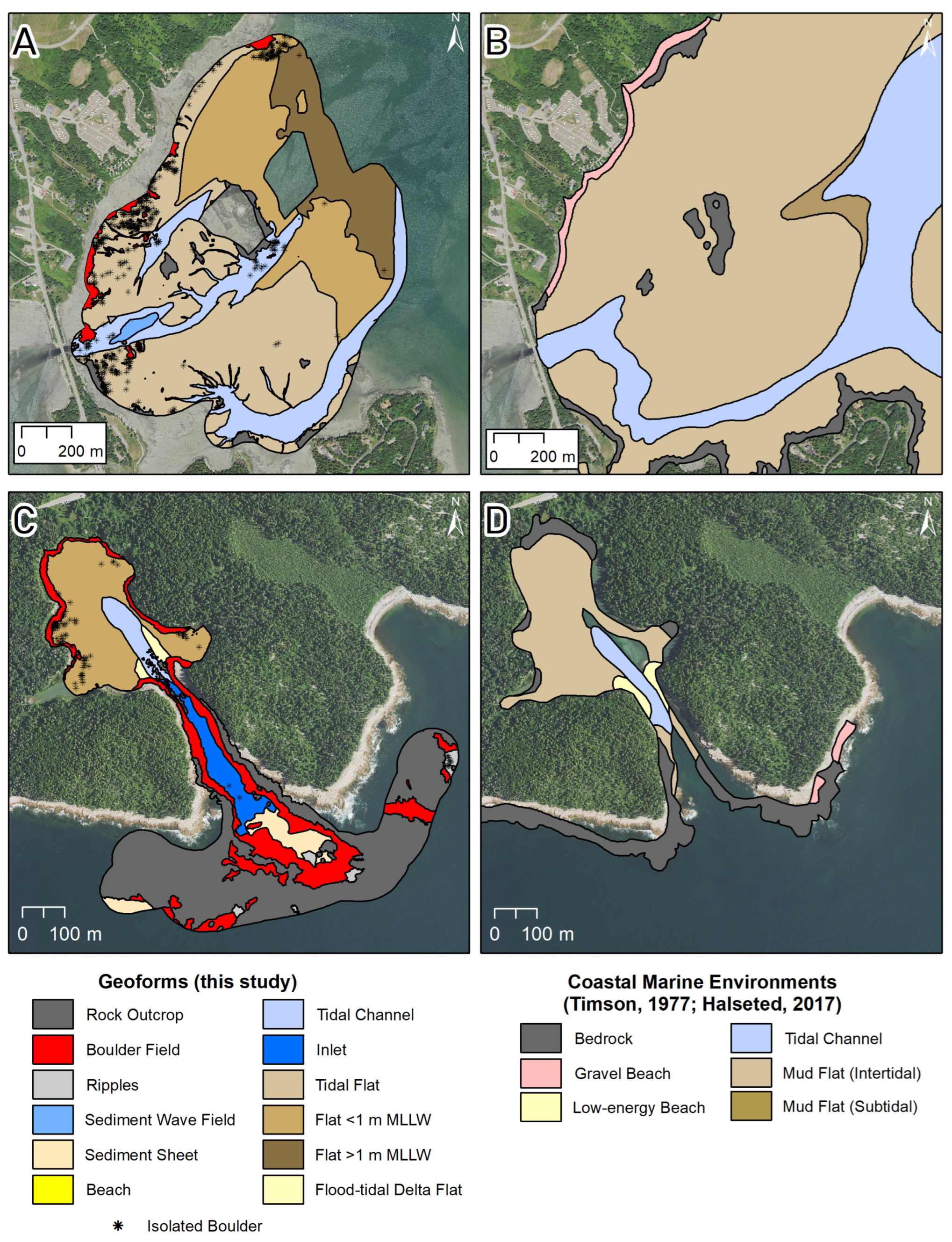
While CMECS has been applied elsewhere in Maine and the adjacent Gulf of Maine [8,40,41], this represents, to our knowledge, the first detailed application of the classification on rocky intertidal areas in the region. Large, regional projects that focused on Gulf of Maine scale mapping [8] covered these areas; however, the map detail was substantially less than the maps presented here; examples of this include the Thompson Island study site that was mapped as a “Flat” with no additional information provided. Other mapping efforts provided similar units to the Geoform units interpreted here, albeit with less detail. Figure 16 compares the mapping of Timson [4] with the interpreted Geoform units for Thompson Island and Ship Harbor. Notable details missing on the older mapping include the isolated boulders at Thompson Island and boulder fields within Ship Harbor. The state-wide mapping of the coastal environments of Maine, mapped by Timson [4] and later digitized [5,6], remains an excellent resource. The mapping presented here complements existing maps by offering a more detailed approach to delineating geologic habitats, biologic features (e.g., mussels), and other seafloor features. These higher-resolution data can also allow for finer-scale abiotic–biotic relationships to be assessed. An important note here is that the mapping effort undertaken in this study is appropriate for local-scale or site-specific when higher resolution data are needed; mapping the entire state of Maine at the scale used in this study would not be practical, and tradeoffs remain between mapping detail and efficiency.
Intertidal habitats represent particularly important habitats in Maine. Given the high tidal range and 8500 km (5300 mi) of coastline, Maine has 587 km2 (145,000 acres) of intertidal habitat [42]; 44% of the intertidal zone is mudflats and 25% is rocky [42]. Given both the dynamic nature of these environments and the sensitivity of the organisms to changes in water temperature and sea level rise due to climate change [43,44], seafloor mapping the physical and biological communities to gain a holistic understanding of the various species, habitats and ecological function is vital to effectively managing these environments now and into the future. This sensitivity is especially important within the Gulf of Maine, which has undergone rapid warming in the 21st century [45], including heatwaves that have led to changes in commercially important fish, shellfish, and macroalgae [46,47]. The Thompson Island site was dominated by intertidal and shallow subtidal flats, which are important for bloodworms (Glycera dibranchiate) [48] and documented mussel fisheries. Both species contribute substantially to the Maine fishing community, with landings of blue mussels (Mytilus edulis) exceeding 430 metric tons (MT) in 2022 worth >$4,000,000 [49]. Bloodworm (Glycera dibranchiate) landings in 2022 were >100 MT, with a value of >$4,700,000 [49]. The dredge trails mapped at Thompson Island ranged from distinct to faintly visible, suggesting some reworking of the seafloor here. Understanding the short- and long-term impacts of these harvesting activities is important for sustaining fishing activities and the natural ecosystem. For example, trails left from harvesting bloodworms (Glycera dibranchiate) persisted for >5 months on Maine mudflats [50]; and given this, it is likely dredge trails from hydraulic mussel harvesting, which are much larger, persist for longer.
Underwater video imagery was a vital component of the mapping efforts. Traditional sediment grab sampling was not useful in rocky habitats, as the sampler “bounced” off of the rocky substrate and did not return a representative sample. The underwater imagery provides important geologic content, even when a sample was recovered, and was useful for indicating the heterogeneity of the seafloor at these sites. The videos also provided a qualitative assessment of species distribution; of note, this included blue mussels (Mytilus edulis), rock crabs (Cancer irroratus), and sand dollars (Echinarachnius parma). European green crabs (Carcinus maenas) were also identified at the Thompson Island and Ship Harbor study areas. These crabs are an invasive species that have had negative impacts on native species, particularly soft-shelled clams (Mya arenaria) and rock crabs (Cancer irroratus), which are both valuable commercial species in Maine [51,52,53]. European green crabs have also been linked to the decline in eelgrass (Zostera marina) [54] and erosion of salt marshes [55,56] elsewhere in Maine. Identification of this species further documents their extent and persistence in Maine tidal waters.
Overall, the current CMECS terminology was suitable for classifying rocky and intertidal environments. The only term that was lacking from the Geoform component was the inclusion of a term for sorted bedforms (aka Rippled-scour repressions) [39,57]. These features were mapped as “Ripples” in the Geoform; however, sorted bedforms are ubiquitous along shorefaces around the world, including in the various national seashores and coastal national parks [58,59,60] and should be included within future revisions of CMECS. These sorted bedforms have also been mapped elsewhere in the Gulf of Maine [2,61]. Future revisions to CMECS should consider the scale of the Geoforms; many of the terms used to map the geomorphology here were considered “level 1” Geoforms, with a scale >1 km2. While users of CMECS are encouraged to apply Geoform Component map units as appropriate to the scale of the mapping [1], more flexibility should be considered in future reiterations of CMECS.
The mapping effort presented here supports the strong need for continued mapping and monitoring into the future to continue to understand these study areas and how they are being impacted by both climate change and anthropogenic activities. The importance of periodically mapping submerged environments, especially in dynamic near-shore areas, is hard to overstate. These mapping efforts allow management intervention to be properly considered and science-based decisions to be made. Similar mapping completed prior to the 2012 and 2016 heatwaves would have quantified changes in macrofaunal species and community distribution. Similarly, areas could be reassessed for changes to the physical environment following a storm event, such as the series of storms that occurred in January 2024, which resulted in substantial erosion and sediment overwash at ACAD and undoubtedly impacted submerged habitats and species. Elsewhere, repeat surveys of NPS areas have offered insight into changes to the seafloor following storm events [35,62]. Repeat mapping also facilitates changes assessment related to anthropogenic impacts on the seafloor, both new disturbances as well as recovery of prior disturbances. For example, future mapping efforts at Thompson Island would determine the persistence of the hydraulic dredge trails from commercial shellfish harvesting.
The high degree of geologic heterogeneity of these areas is related to the complex geologic history of the region, specifically the Late Wisconsinan rapid sea level rise during the late Pleistocene and Holocene and resulting deposition in a variety of coarse and fine-grained glacial environments. Ultimately, the lack of stratigraphic data (e.g., sediment cores and seismic reflection profiles) limits a more detailed discussion of the geologic formation of these areas and is beyond the scope of this paper. However, inferences can be made on the general controls of the depositional processes in these areas. The shallow subtidal and intertidal geomorphology of the region is largely controlled by the combination of the bedrock composition and morphology, distribution of glacial sediment, and modern coastal processes (e.g., waves, tidal currents) [63]. The bedrock topography creates patterns of wave sheltering, while the glacial deposits provide a source of erodible sediment [64]. The glacial deposits adjacent to both Compass Harbor and Thompson Island largely consist of Presumpscot formation [16] which provides an abundant source for fine-grained sediment (largely silty clay) while it was eroded during marine transgression. However, the substantial difference in energy controls the deposition at these two sites. Fine-grained sediment dominates the relatively sheltered Thompson Island, except where boulders erode from the glacial till to form fringing deposits along the shoreline [63] or crop out within other habitats. Conversely, deposition of the fine-grained sediment (e.g., mud) eroded from the glacial deposits at Compass Harbor is inhibited by the relatively high wave-energy. These observations largely match the geomorphic zones identified for coastal Maine [63], where more protected sites (i.e., Thompson Island, Inner Ship Harbor (Figure 11 and Figure 12)) are dominated by mud flats and marshes, while more exposed areas (e.g., Compass harbor and outer portions of Ship Harbor (Figure 9 and Figure 11)) are dominated by bedrock outcrop and gravelly coastal deposits. Frazer Creek (Figure 10), with the complicated bedrock outcrop and various energy levels, has characteristics of both sheltered and more exposed areas. The features around Ship Island and portions of Frazer Creek are similar to those discussed elsewhere in the region [65,66]. The distribution of geologic habitats at these study sites contributes to the evolving literature on estuarine facies within the rock record [66,67,68,69,70].

Supplementary Materials

The following supporting information can be downloaded at https://www.mdpi.com/article/10.3390/geosciences14100256/s1, Supplemental Table S1. Underwater video imagery was collected in this study.

Author Contributions

Conceptualization, J.K., B.C., M.L.B., C.J. and B.O.; methodology, J.K., B.C. and B.O.; fieldwork; B.O., B.C., J.K. and A.M.; software, B.C. and B.O.; formal analysis, B.O., M.L.B., C.S., G.R. and C.R.; data curation, B.O. and J.K.; writing—original draft preparation, B.O. and M.L.B.; writing—review and editing., B.O., M.L.B. and C.J.; funding acquisition, J.K. and C.J. All authors have read and agreed to the published version of the manuscript.

Funding

This research was funded by the National Park Service (NPS) (Project ACAD-00583) through the North Atlantic Coast Cooperative Ecosystem Studies Unit (CESU) Task Agreement P20AC00748 N Research Conducted Under Permit #: ACAD-2021-SCI-0075.

Data Availability Statement

Final data products and maps will be stewarded on the NPS Integrated Resource Management Applications (IRMA) Portal. Raw sonar data will be submitted to NOAA NCEI for archive and public access. Underwater videos were stored as *.mp4 files and were then uploaded to YouTube and are available there (See Supplemental Table S1).

Acknowledgments

Carol Gibson and Danielle Cares (URI/GSO) Contributed greatly with help on logistics for travel/fieldwork as well as report preparation, GIS organization, and sediment sample preparation. Thomas Trott provided detailed species counts on surface sediment grab samples. The authors thank two anonymous reviewers for their insightful comments and edits.

Conflicts of Interest

The authors declare no conflicts of interest. The funders had no role in the design of the study, in the collection, analyses, or interpretation of data, in the writing of the manuscript, or in the decision to publish the results.

References

  1. FGDC. Coastal and Marine Ecological Classification Standard (CMECS); FGDC: Washington, DC, USA, 2012.
  2. Barnhardt, W.A.; Belknap, D.F.; Kelley, A.R.; Kelley, J.T.; Dickson, S.M. Surficial Geology of the Maine Innter Continental Shelf: Mount Desert Island to Jonesport, Maine; Geologic Map No 96-12: Maine Geological Survey, Scale 1:100,000; Maine Geological Survey: Augusta, ME, USA, 1996.
  3. Hart, T.E.; Neckles, H.A.; Kobb, B.S. Priority Data on Marine and Estuarine Resources within Northeastern National Parks Inventory and Acquisition Needs; Natural Resource Report NPS/NCBN/NRR—2013/612; National Park Service: Fort Collins, CO, USA, 2013. [Google Scholar]
  4. Timson, B.S. Coastal Marine Geologic Maps: Maine Geological Survey Open File Report 77-1; Maine Geological Survey: Augusta, ME, USA, 1977.
  5. Ward, A.E. Maine’s Coastal Welands: I. Types, Distributions, Rankings, Functions and Values; Report DEPLW1999-13; Bureau of Land and Water Quality, Deivision of Environmental Assessment, Department of Environmental Protection, State of Maine: Agusta, ME, USA, 1999.
  6. Halsted, C. Maine Coastal Geologic Environments; Maine Geological Survey: Augusta, ME, USA, 2017.
  7. Masetti, G.; Mayer, L.A.; Ward, L.G. A Bathymetry- and Reflectivity-Based Approach for Seafloor Segmentation. Geosciences 2018, 8, 14. [Google Scholar] [CrossRef]
  8. TetraTech. Gulf of Maine–Geoform Data Development: Report Prepared for the Department of Commerce, National Oceanic and Atmospheric Administration, National Ocean Service Office for Coastal Management; TetraTech: Fairfax, VA, USA, 2021. [Google Scholar]
  9. Reusch, D.N. Bedrock Geology of the Salsbury Cove Quadrangle, Maine: Maine Geological Survey, Open-File Map 03-91, Color Map, Scale 1:24,000. Maine Geological Survey Maps. 38; Maine Geological Survey: Agusta, ME, USA, 2003.
  10. Braun, D.D. Bedrock Geology of the Southwestern Portion of the Bar Harbor Quadrangle, Maine: Maine Geological Survey, Open-File Map 19-13, Color Map, Scale 1:24,000. Maine Geological Survey Maps. 2115; Maine Geological Survey: Agusta, ME, USA, 2019.
  11. Braun, D.D. Bedrock Geology of the Northern Portion of the Bass Harbor Quadrangle, Maine: Maine Geological Survey, Open-File Map 19-10, Color Map, Scale 1:24,000. Maine Geological Survey Maps. 2112; Maine Geological Survey: Agusta, ME, USA, 2019.
  12. Osberg, P.H.; Hussey, A.M., II; Boone, G.M. Bedrock Geologic Map of Maine: Maine Geological Survey, 1 Plate, Correlation Chart, Tectonic Inset Map, Metamorphic Inset Map, Color Geologic Map, Cross Sections, Scale 1:500,000. Maine Geological Survey Maps. 23; Maine Geological Survey: Agusta, ME, USA, 1985.
  13. Braun, D.D.; Davis, P.T.; Kelley, J.T.; Lowell, T.V. Mount Desert Island glacial deposits, landforms, and place in the regional deglaciation sequence along with some Pre-Pleistocene bedrock geology. In Proceedings of the Guidebook for the 81st Annual Reunion of the Northeastern Friends of the Pleistocene, Bar Harbor, ME, USA, 1–3 June 2018. [Google Scholar]
  14. Gilman, R.A.; Chapman, C.A.; Lowell, T.V.; Borns, H.W., Jr. The Geology of Mount Desert Island; A Visitor’s Guide to the Geology of Acadia National Park: Maine Geological Survey, Bulletin 38; Maine Geological Survey: Agusta, ME, USA, 1988.
  15. Schafer, J.P.; Hartshorn, J. (Eds.) The Quaternary of New England; Princeton University Press: Princeton, NJ, USA, 1965; pp. 113–127. [Google Scholar]
  16. Koester, A.; Shakun, J.; Bierman, P.; Davis, P.; Corbett, L.; Braun, D.; Zimmerman, S. Rapid thinning of the Laurentide Ice Sheet in coastal Maine, USA, during late Heinrich Stadial 1. Quat. Sci. Rev. 2017, 163, 180–192. [Google Scholar] [CrossRef]
  17. Braun, D.D.; Lowell, T.V.; Weddle, T.K. Surficial Geology of Mount Desert Island: Maine Geological Survey, Open-File Map 16-1; Maine Geological Survey: Agusta, ME, USA, 2016.
  18. Thompson, W.B.; Borns, H. Surficial Geologic Map of Maine, 1st ed.; Maine Geological Survey: Agusta, ME, USA, 1985.
  19. Belknap, D.F.; Anderson, B.A.; Anderson, R.S.; Anderson, W.A.; Borns, H.W., Jr.; Jacobson, G.L.; Kelley, J.T.; Shipp, R.C.; Smith, D.C.; Stuckenrath, R., Jr.; et al. (Eds.) Late Quaternary Sea-Level Changes in Maine; Society for Sedimentary Geology: Claremore, OK, USA, 1987; Volume 41, pp. 71–85. [Google Scholar]
  20. NOAA-NOS. Datums for 8413320. Available online: https://tidesandcurrents.noaa.gov/datums.html?id=8413320 (accessed on 9 September 2022).
  21. Hayes, M.O. Barrier island morphology as a function of tidal and wave regime. In Barrier Islands from the Gulf of St. Lawrence to the Gulf of Mexico; Leatherman, S.P., Ed.; Academic Press: New York, NY, USA, 1979; pp. 1–27. [Google Scholar]
  22. Valentine, P.C.; Todd, B.J.; Kostylev, V.E. Classification of marine sublittoral habitats, with application to the northeastern North America Region. Am. Fish. Soc. Symp. 2005, 41, 183–200. [Google Scholar]
  23. Oakley, B.A.; Alvarez, J.D.; Boothroyd, J.C. Benthic Geologic Habitats of Shallow Estuarine Environments: Greenwich Bay and Wickford Harbor, Narragansett Bay, Rhode Island, U.S.A. J. Coast. Res. 2012, 28, 760–773. [Google Scholar] [CrossRef]
  24. Borelli, M.; Fox, S.E.; Shumchenia, E.; Kennedy, C.G.; Oakley, B.A.; Hubeny, J.B.; Love, H.; Smith, T.L.; Legare, B.; Mittermayr, A.; et al. Submerged Marine Habitat Mapping at Cape Cod National Seashore: A Post-Hurricane Sandy Study. Natural Resource Report. NPS/NCBN/NRR—2019/1877; National Park Service: Fort Collins, CO, USA, 2019.
  25. Grothues, T.M.; Levin, D.; Psuty, N.; Habeck, A.; Petrecca, R.; Dobarro, J.; Taghon, G.; De Luca, M.P. Submerged Marine Habitat Mapping at Sandy Hook Unit, Gateway National Recreation Area: A Post-Hurricane Sandy Study. Natural Resource Report. NPS/NCBN/NRR—2019/1865; National Park Service: Fort Collins, CO, USA, 2019.
  26. LaFrance Bartley, M.; King, E.L.; Oakley, B.A.; Caccioppoli, B.J. Submerged Marine Habitat Mapping at Fire Island National Seashore: A Post-Hurricane Sandy Study. Natural Resource Report. NPS/NCBN/NRR—2018/1797; National Park Service: Fort Collins, CO, USA, 2019.
  27. Trembanis, A.; Miller, D.C.; Ebula, E.; Rusch, H.M.; Rothermel, E.R. Submerged Marine Habitat Mapping at Assateague Island National Seashore A Post-Hurricane Sandy Study: Natural Resource Report NPS/NCBN/NRR—2019/1871; National Park Service: Fort Collins, CO, USA, 2019.
  28. Eastwood, P.D.; Souissi, S.; Rogers, S.I.; Coggan, R.A.; Brown, C.J. Mapping seabed assemblages using comparative top-down and bottom-up classification approaches. Can. J. Fish. Aquat. Sci. 2006, 63, 1536–1548. [Google Scholar] [CrossRef]
  29. Hewitt, J.; Thrush, S.; Legendre, P.; Funnell, G.; Ellis, J.; Morrison, M. Mapping of marine soft-sediment communities: Integrated sampling for ecological interpretation. Ecol. Appl. 2004, 14, 1203–1216. [Google Scholar] [CrossRef]
  30. Kostylev, V.E.; Todd, B.J.; Fader, G.B.; Courtney, R.; Cameron, G.D.; Pickrill, R.A. Benthic habitat mapping on the Scotian Shelf based on multibeam bathymetry, surficial geology and sea floor photographs. Mar. Ecol. Prog. Ser. 2001, 219, 121–137. [Google Scholar] [CrossRef]
  31. LaFrance, M.; King, J.W.; Oakley, B.A.; Pratt, S. A comparison of top-down and bottom-up approaches to benthic habitat mapping to inform offshore wind energy development. Cont. Shelf Res. 2014, 83, 24–44. [Google Scholar] [CrossRef]
  32. NOAA. Observed water levels at 8413320, Bar Harbor, ME. NOAA/NOS/CO-OPS, Ed. 2024. Available online: https://tidesandcurrents.noaa.gov/waterlevels.html?id=8413320 (accessed on 15 October 2021).
  33. Mittermayr, A.; Legare, B.J.; Kennedy, C.G.; Fox, S.E.; Borrelli, M.B. Using CMECS to create benthic habitat maps for Pleasant Bay, Cape Cod, Massachusetts. Northeast. Nat. 2020, 27, 22–47. [Google Scholar] [CrossRef]
  34. Wentworth, C.K. A scale of grade and class terms for clastic sediments. J. Geol. 1922, 30, 377–392. [Google Scholar] [CrossRef]
  35. LaFrance Bartley, M.; King, J.W.; Oakley, B.A.; Caccioppoli, B.J. Post-Hurricane Sandy Benthic Habitat Mapping at Fire Island National Seashore, New York, USA, Utilizing the Coastal and Marine Ecological Classification Standard (CMECS). Estuaries Coasts 2022, 45, 1070–1094. [Google Scholar] [CrossRef]
  36. Clarke, K.; Gorley, R. Getting Started with PRIMER v7: Getting Started with PRIMER v7. PRIMER-e: Plymouth, UK. Plymouth Marine Laboratory. 2015. Available online: https://learninghub.primer-e.com/books/primer-v7-user-manual-tutorial (accessed on 22 September 2024).
  37. Clarke, K.R. Non-parametric multivariate analyses of changes in community structure. Aust. J. Ecol. 1993, 18, 117–143. [Google Scholar] [CrossRef]
  38. Clarke, K.R.; Tweedley, J.R.; Valesini, F.J. Simple shade plots aid better long-term choices of data pre-treatment in multivariate assemblage studies. J. Mar. Biol. Assoc. UK 2014, 94, 1–16. [Google Scholar] [CrossRef]
  39. Cacchione, D.A.; Drake, D.E.; Grant, W.D.; Tate, G.B. Rippled scour depressions on the inner continental shelf off central California. J. Sediment. Res. 1984, 54, 1280–1291. [Google Scholar]
  40. Calvert, J.; McGonigle, C. Chapter 26—Benthic community structure at a remote temperate rocky reef in the Gulf of Maine, Cashes Ledge. In Seafloor Geomorphology as Benthic Habitat, 2nd ed.; Harris, P.T., Baker, E., Eds.; Elsevier: Amsterdam, The Netherlands, 2020; pp. 461–471. [Google Scholar] [CrossRef]
  41. Ozmon, I.M.; Dobbs, K.; Enterline, C.; Dickson, S.M.; Nixon, M.E. Subtidal benthic habitat mapping with CMECS in mid-coast Maine. In Proceedings of the Coastal and Estuarine Research Federation Biennial Conference, Providence, RI, USA, 5–9 November 2017. [Google Scholar]
  42. Ward, A.E. Maine’s Coastal Wetlands; Bureau of Land and Water Quality, Division of Environmental Assessment: Augusta, ME, USA, 1999.
  43. Amstutz, A.; Firth, L.B.; Spicer, J.I.; Hanley, M.E. Facing up to climate change: Community composition varies with aspect and surface temperature in the rocky intertidal. Mar. Environ. Res. 2021, 172, 105482. [Google Scholar] [CrossRef] [PubMed]
  44. Garza, C. Landscape Ecology in the Rocky Intertidal: Opportunities for Advancing Discovery and Innovation in Intertidal Research. Curr. Landsc. Ecol. Rep. 2019, 4, 83–90. [Google Scholar] [CrossRef]
  45. Whitney, N.M.; Wanamaker, A.D.; Ummenhofer, C.C.; Johnson, B.J.; Cresswell-Clay, N.; Kreutz, K.J. Rapid 20th century warming reverses 900-year cooling in the Gulf of Maine. Commun. Earth Environ. 2022, 3, 179. [Google Scholar] [CrossRef]
  46. Bricknell, I.R.; Birkel, S.D.; Brawley, S.H.; Van Kirk, T.; Hamlin, H.J.; Capistrant-Fossa, K.; Huguenard, K.; Van Walsum, G.P.; Liu, Z.L.; Zhu, L.H.; et al. Resilience of cold water aquaculture: A review of likely scenarios as climate changes in the Gulf of Maine. Rev. Aquac. 2021, 13, 460–503. [Google Scholar] [CrossRef]
  47. Pershing, A.J.; Mills, K.E.; Dayton, A.M.; Franklin, B.S.; Kennedy, B.T. Evidence for adaptation from the 2016 marine heatwave in the Northwest Atlantic Ocean. Oceanography 2018, 31, 152–161. [Google Scholar] [CrossRef]
  48. Sypitkowski, E.; Ambrose, W.G.; Bohlen, C.; Warren, J. Catch statistics in the bloodworm fishery in Maine. Fish. Res. 2009, 96, 303–307. [Google Scholar] [CrossRef]
  49. DMR. Maine Department of Marine Resources Hisorical Maine Fisheries Landings Data. Available online: https://www.maine.gov/dmr/fisheries/commercial/landings-program/historical-data (accessed on 14 March 2024).
  50. Sypitkowski, E.; Bohlen, C.; Ambrose, W.G. Estimating the frequency and extent of bloodworm digging in Maine from aerial photography. Fish. Res. 2010, 101, 87–93. [Google Scholar] [CrossRef]
  51. Griffien, B.D.; Riley, M.E. Potential impacts of invasive crabs on one life history strategy of native rock crabs in the Gulf of Maine. Biol. Invasions 2015, 17, 2533–2544. [Google Scholar] [CrossRef]
  52. McClenachan, L.; O’Connor, G.; Reynolds, T. Adaptive capacity of co-management systems in the face of environmental change: The soft-shell clam fishery and invasive green crabs in Maine. Mar. Policy 2015, 52, 26–32. [Google Scholar] [CrossRef]
  53. Tan, E.B.P.; Beal, B.F. Interactions between the invasive European green crab, Carcinus maenas (L.), and juveniles of the soft-shell clam, Mya arenaria L., in eastern Maine, USA. J. Exp. Mar. Biol. Ecol. 2015, 462, 62–73. [Google Scholar] [CrossRef]
  54. Neckles, H.A. Loss of Eelgrass in Casco Bay, Maine, Linked to Green Crab Disturbance. Northeast. Nat. 2015, 22, 478–500. [Google Scholar] [CrossRef]
  55. Aman, J.; Grimes, K.W. Measuring Impacts of Invasive European Green Crabs on Maine Salt Marshes: A Novel Approach: Report to the Maine Outdoor Heritage Fund; Wells National Estuarine Research Reserve: Wells, ME, USA, 2016.
  56. Raposa, K.B.; Goldstein, J.S.; Grimes, K.W.; Mora, J.; Stacey, P.E. A comparative assessment of salt marsh crabs (Decapoda: Brachyura) across the National Estuarine Research Reserves in New England, USA. J. Crustac. Biol. 2019, 40, 67–75. [Google Scholar] [CrossRef]
  57. Trembanis, A.C.; Hume, T.M. Sorted bedforms on the inner shelf off northeastern New Zealand: Spatiotemporal relationships and potential paleo-environmental implications. Geo-Mar. Lett. 2011, 31, 203–214. [Google Scholar] [CrossRef]
  58. Goff, J.A.; Flood, R.D.; Austin, J.A., Jr.; Schwab, W.C.; Christensen, B.; Browne, C.M.; Denny, J.F.; Baldwin, W.E. The impact of Hurricane Sandy on the shoreface and inner shelf of Fire Island, New York: Large bedform migration but limited erosion. Cont. Shelf Res. 2015, 98, 13–25. [Google Scholar] [CrossRef]
  59. Pendleton, E.A.; Brothers, L.L.; Thieler, E.R.; Sweeney, E.M. Sand ridge morphology and bedform migration patterns derived from bathymetry and backscatter on the inner-continental shelf offshore of Assateague Island, USA. Cont. Shelf Res. 2017, 144, 80–97. [Google Scholar] [CrossRef]
  60. Thieler, E.R.; Foster, D.S.; Himmelstoss, E.A.; Mallinson, D.J. Geologic framework of the northern North Carolina, USA inner continental shelf and its influence on coastal evolution. Mar. Geol. 2014, 348, 113–130. [Google Scholar] [CrossRef]
  61. Hein, C.; FitzGerald, D.; Barnhardt, W. Holocene reworking of a sand sheet in the Merrimack Embayment, Western Gulf of Maine. J. Coast. Res. 2007, 50, 863–867. [Google Scholar] [CrossRef]
  62. Trembanis, A.; Abla, A.; Haulsee, K.; DuVal, C. Benthic Habitat Morphodynamics-Using Remote Sensing to Quantify Storm-Induced Changes in Nearshore Bathymetry and Surface Sediment Texture at Assateague National Seashore. J. Mar. Sci. Eng. 2019, 7, 371. [Google Scholar] [CrossRef]
  63. Shipp, R.C.; Staples, S.A.; Ward, L.G. Controls and zonation of geomorphology along a glaciated coast, Gouldsboro Bay, Maine. In Glaciated Coasts; Elsevier: Amsterdam, The Netherlands, 1987; pp. 209–231. [Google Scholar]
  64. Kelley, J.T.; Belknap, D.F.; Kelley, A.R.; Claesson, S.H. A model for drowned terrestrial habitats with associated archeological remains in the northwestern Gulf of Maine, USA. Mar. Geol. 2013, 338, 1–16. [Google Scholar] [CrossRef]
  65. Duffy, W.; Belknap, D.F.; Kelley, J.T. Morphology and stratigraphy of small barrier-lagoon systems in Maine. Mar. Geol. 1989, 88, 243–262. [Google Scholar] [CrossRef]
  66. Mack, G.H.; Leeder, M.; Perez-Arlucea, M.; Bailey, B. Sedimentology, paleontology, and sequence stratigraphy of Early Permian estuarine deposits, South-Central New Mexico, USA. Palaios 2003, 18, 403–420. [Google Scholar] [CrossRef]
  67. Reinson, G.E. Transgressive Barrier Island and Estuarine Systems; Walker, R.G., Ed.; Geological Association of Canada: St. Johns, NL, Canada, 1992; pp. 174–194.
  68. Abrahim, G.M.; Nichol, S.L.; Parker, R.J.; Gregory, M.R. Facies depositional setting, mineral maturity and sequence stratigraphy of a Holocene drowned valley, Tamaki Estuary, New Zealand. Estuar. Coast. Shelf Sci. 2008, 79, 133–142. [Google Scholar] [CrossRef]
  69. Dalrymple, R.W.; Zaitlin, B.A.; Boyd, R. Estuarine facies models; conceptual basis and stratigraphic implications. J. Sediment. Res. 1992, 62, 1130–1146. [Google Scholar] [CrossRef]
  70. Longhitano, S.G.; Mellere, D.; Steel, R.J.; Ainsworth, R.B. Tidal depositional systems in the rock record: A review and new insights. Sediment. Geol. 2012, 279, 2–22. [Google Scholar] [CrossRef]
Figure 1. Location map of the four field areas mapped in Acadia National Park. The crosshatch polygons show the extent of the National Park on Mount Desert Island and adjacent areas (NPS, 2019).
Geosciences 14 00256 g001
Figure 2. Side-scan sonar mosaics for each of the four study areas. (A) Thompson Island; (B) Compass Harbor; (C) Ship Harbor; (D) Frazer Creek.
Geosciences 14 00256 g002
Figure 3. Benthic depth zones of the four study areas. (A) Thompson Island; (B) Compass Harbor; (C) Ship Harbor; (D) Frazer Creek. Note the added subclass of the Shallow infralittoral zone (0 to 1 m MLLW) added to better emphasize the intertidal flats, particularly in Frazer Creek and at Thompson Island. The inner portion of Ship Harbor was not able to be tidally corrected.
Geosciences 14 00256 g003
Figure 4. Location of sediment samples attempted in the four study areas. Pie charts show the percentage of sand, silt, and clay for measured samples. Green dots show the location of samples where no sediment was recovered. All stations were imaged using underwater video imagery. Yellow lines show the location of video drifts. (A) Thompson Island; (B) Compass Harbor; (C) Ship Harbor; (D) Frazer Creek. See Figure 1 for the locations. 2018 NAIP Image Basemap.
Geosciences 14 00256 g004
Figure 5. Example underwater video images collected from (See Figure 4 for station locations). The Ponar sampler visible in panels (A,CE) is 20 cm across. The white PVC frame in panels B and F is 25 cm across. A. Thompson Island station 16. Muddy sand with Blue Mussels (Mytilus edulis) and an isolated boulder. (B) Thompson Island drift 1. Gravelly sediment within a tidal channel. (C) Thompson Island station 4 Slightly gravelly fine sand with abundant blue mussels (Mytilus edulis). (D) Compass Harbor station 3. Gravelly sediment sheet with boulders and bedrock outcrop. (E) Compass Harbor station 4. Gravelly sediment with boulders. (F) Compass Harbor drift 4. Gravelly sand with abundant sand dollars (Echinarachnius parma).
Geosciences 14 00256 g005
Figure 6. CMECS Substrate (subgroup). (A) Thompson Island; (B) Compass Harbor; (C) Ship Harbor; (D) Frazer Creek. See Figure 1 for the locations. 2018 NAIP Image Basemap.
Geosciences 14 00256 g006
Figure 7. CMECS Geoforms mapped for the four study areas. (A) Thompson Island; (B) Compass Harbor; (C) Ship Harbor; (D) Frazer Creek. See Figure 1 for the locations. 2018 NAIP Image Basemap.
Geosciences 14 00256 g007
Figure 8. (A) Thompson Island side-scan sonar mosaic, showing the representative hydraulic dredge trails visible on the side-scan sonar mosaic (2018 NAIP Basemap). (B) Side-scan sonar mosaic showing cross-cutting hydraulic dredge trails (1) and faint (older) hydraulic dredge trails (2). The blotchy sonar return on the side-scan sonar mosaic (3) is produced by the presence of mussels.
Geosciences 14 00256 g008
Figure 9. Benthic geologic habitats of Compass Harbor; see Figure 1 for the locations. 2018 NAIP Image Basemap.
Geosciences 14 00256 g009
Figure 10. Benthic geologic habitats of Frazer Creek; see Figure 1 for the locations. 2018 NAIP Image Basemap.
Geosciences 14 00256 g010
Figure 11. Benthic geologic habitats of Ship Harbor; see Figure 1 for the locations. 2018 NAIP Image Basemap.
Geosciences 14 00256 g011
Figure 12. Benthic geologic habitats of Thompson Island; see Figure 1 for the locations. 2018 NAIP Image Basemap.
Geosciences 14 00256 g012
Figure 13. nMDS plot of macrofaunal community composition for each grab sample site (n = 30), excluding samples that contained 0–5 individuals (n = 13). The plot shows samples separated out according to the study area, indicating macrofaunal communities are more similar within a given study area and more distinct across study areas.
Geosciences 14 00256 g013
Figure 14. Resulting CMECS classification outputs for (A) Compass Harbor, (B) Ship Harbor, and (C) Frazer Creek. The map units are defined by the Geoform Component (Geoform classification), and the grab sample locations are defined by the Biotic Component (Biotic Community named according to dominant species). The development of Biotopes in these study areas was not possible due to an insufficient number of benthic macrofaunal samples.
Geosciences 14 00256 g014
Figure 15. Resulting CMECS classification outputs for Thompson Island. The map units are defined by the Geoform Component (Geoform classification), and the grab sample locations are defined by the Biotic Component (Biotic Community named according to dominant species). The development of Biotopes in this study area was not possible due to the inconsistency of dominant species among samples within a given map unit type.
Geosciences 14 00256 g015
Figure 16. Comparison of the Geoform units from this study (A,C) with those mapped Timson [4] (B,D) for Thompson Island (A,B) and Ship Harbor (C,D).
Geosciences 14 00256 g016
Table 1. Total side-scan sonar coverage for the four areas mapped around Acadia National Park in September 2021.
LocationArea Mapped (km2)Area Mapped (Acre)
Compass Harbor0.1435
Frazer Creek0.2665
Ship Harbor0.3074
Thompson Island1.4338
Total2.1512
Table 2. Sediment sample analysis for the four study areas.
Sample IDLabelLatitudeLongitudePercent SandPercent MudPercent Clay
Compass Harbor 1CH-144.37571−68.19293100.00%0.00%0.00%
Compass Harbor2CH-244.37648−68.19397100.00%0.00%0.00%
Frazer Creek 1FC-144.37654−68.0728568.20%28.30%0.00%
Frazer Creek 2FC-244.3784−68.072446.10%47.30%0.00%
Frazer Creek 5FC-544.38281−68.0744140.50%48.90%0.00%
Frazer Creek 6FC-644.37936−68.0741643.00%46.80%0.00%
Frazer Creek 7FC-744.38057−68.07658100.00%0.00%0.00%
Frazer Creek 8FC-844.37813−68.0750293.90%5.00%0.00%
Ship Harbor 1SH-144.22925−68.3249952.00%44.30%3.70%
Ship Harbor 2SH-244.2304−68.3251231.10%61.90%7.00%
Ship Harbor 3SH-344.22858−68.3220548.20%46.90%4.90%
Ship Harbor 6SH-644.22564−68.32054100.00%0.00%0.00%
Thompson Island 1TI-144.43924−68.357740.20%50.60%9.20%
Thompson Island 2TI-244.438−68.357725.40%62.40%12.20%
Thompson Island 4TI-444.43592−68.361520.00%67.40%12.70%
Thompson Island 5TI-544.43366−68.3631426.40%64.40%9.30%
Thompson Island 6TI-644.43354−68.3647223.40%63.70%12.90%
Thompson Island 7TI-744.43198−68.3651721.50%66.70%11.90%
Thompson Island 8TI-844.43072−68.3644180.30%15.90%3.90%
Thompson Island 9TI-944.4312−68.3617925.90%61.10%13.00%
Thompson Island 10TI-1044.43036−68.3588722.90%63.70%13.40%
Thompson Island 11TI-1144.42946−68.3624122.80%64.90%12.30%
Thompson Island 12TI-1244.42904−68.3645621.30%67.50%11.10%
Thompson Island 14TI-1444.42718−68.3576123.40%65.10%11.60%
Thompson Island 15TI-1544.42949−68.3567626.20%63.00%10.90%
Thompson Island 16TI-1644.43015−68.3567636.60%49.80%13.60%
Thompson Island 17TI-1744.43142−68.3575720.80%62.70%16.50%
Thompson Island 19TI-1944.43371−68.3597723.40%61.40%15.30%
Thompson Island 20TI-2044.43353−68.3545145.80%44.60%9.60%
Thompson Island 21TI-2144.43362−68.351811.30%76.50%12.20%
Thompson Island 22TI-2244.43512−68.3518115.10%73.30%11.60%
Table 3. Total number of ground-truth sites for each study area (n = 43), at which one benthic grab sample and underwater video footage were recorded (middle column). The number of ground-truth samples that were included for analysis at each study site after removing samples for which 0–5 macrofaunal individuals were recovered (n = 13) (right column).
Study AreaTotal Number of Ground-Truth SamplesNumber of Ground-Truth Samples Included in Biotope Analysis
Thompson Island2221
Frazer Creek82
Compass Harbor64
Ship Harbor73
TOTAL4330
Table 4. Summary of the substrate components, mapped to the subgroup level for the four study areas.
Compass Harbor Substrate (Subgroup)Area (m2)Area (Acres)Percent
Bedrock65,94016.346.3%
Boulder12,8653.29.0%
Bouldery Sand5130.10.4%
Gravelly Sand55,63013.739.1%
Sandy Gravel43281.13.0%
Medium Sand30220.72.1%
Frazer Creek Substrate (Subgroup)
Anthropogenic Rock Rubble250.00.0%
Bedrock88,13721.833.7%
Boulder13,9773.55.3%
Cobble56361.42.2%
Gravelly Mud6210.20.2%
Gravelly Sand41,91810.416.0%
Sandy Silt90,46322.434.6%
Slightly Gravelly Muddy Sand16530.40.6%
Slightly Gravelly Sand19,1654.77.3%
Ship Harbor Substrate (Subgroup)
Bedrock136,95033.845.5%
Boulder58,80414.519.5%
Sandy Cobbley Boulder13,4483.34.5%
Gravelly Sand74951.92.5%
Sandy Gravel22,8105.67.6%
Sandy Silt61,31915.220.4%
Thompson Island Substrate (Subgroup)
Bedrock31,0007.72.26%
Boulder22,7125.61.66%
Fine Sand7940.20.06%
Gravelly Mud21560.50.16%
Gravelly Sand197,90648.914.46%
Sandy Gravel17,0454.21.25%
Sandy Silt811,238200.559.27%
Silty Sand10230.30.07%
Slightly Gravelly Sand80762.00.59%
Slightly Gravelly Sandy Mud276,79068.420.22%
Table 5. Summary of the Geoform units mapped within the four study areas.
Compass HarborArea (m2)Area (Acres)Percent
Rock Outcrop65,94016.346.3%
Boulder Field13,3783.39.4%
Sediment Sheet58,11114.440.8%
Beach12760.30.9%
Ripples35930.92.5%
Frazer Creek
Anthropogenic Rock Rubble250.00.0%
Rock Outcrop88,13721.833.7%
Boulder Field13,9773.55.3%
Sediment Sheet53,08913.120.3%
Channel78,93819.530.2%
Tidal Flat13,2143.35.1%
Terrace14,2163.55.4%
Ship Harbor
Rock Outcrop136,95033.845.5%
Boulder Field58,80414.519.5%
Sediment Sheet12,7693.24.2%
Channel95692.43.2%
Flat61,31915.220.4%
Flood-tidal Delta Flat30910.81.0%
Ripples37860.91.3%
Inlet15,8683.95.3%
Thompson Island
Rock Outcrop31,0007.72.26%
Boulder Field22,7125.61.66%
Tidal Flat613,496151.644.82%
Flat <1 m MLLW313,61277.522.91%
Flat >1 m MLLW163,73340.511.96%
Channel214,47853.015.67%
Sediment Wave Field89132.20.65%
Ripples7940.20.06%
Table 6. SIMPER results for Thompson Island map units.
Map Unit DescriptionNumber of Macrofaunal SamplesSIMPER Average Similarity
Tidal Flat1234.63%
Flat < 1 m MLLW333.65%
Flat > 1 m MLLW260.63%
Channel32.13%
Tidal Sediment Wave Field1n/a
Disclaimer/Publisher’s Note: The statements, opinions and data contained in all publications are solely those of the individual author(s) and contributor(s) and not of MDPI and/or the editor(s). MDPI and/or the editor(s) disclaim responsibility for any injury to people or property resulting from any ideas, methods, instructions or products referred to in the content.