Abstract
In a pilot study, hyperspectral image analysis was applied to four boreholes from the North Midlands Block in Ireland. The selected holes are extremely well characterised lithologically and have a detailed micropalaeontology accurately constraining stratigraphic positions. Hyperspectral facies were defined using features extracted from the hyperspectral data and compared with existing litho- and biostratigraphic logs and samples. These were able to distinguish changes in the lithologies of the cores and were useful for defining unbiased lithological contacts and for regional correlations.
1. Introduction
Ireland’s palaeogeographic position during Mississippian times (from 358.9 to 323.2 Ma) was in the tropics. During the early Carboniferous (from 358.9 to 346.7 Ma), global sea levels started to rise, resulting in a marine transgression from the south, until most of the country became a shallow-water carbonate shelf. Extensional tectonism formed deeper water basins locally (e.g., the Shannon Trough and Dublin Basin). Mixed siliciclastic and carbonate sediments were deposited along the margin of the transgressive shelf sea as it spread successively more northwards. In the south of Ireland, terrigeneous sediments continued to accumulate during most of the Tournaisian (from 358.9 to 346.7 Ma) in the South Munster Basin. During the Viséan (from 346.7 to 330.9 Ma), the differentiation into the basinal and shelf areas continued. The carbonate shelf can be traced eastwards across Wales, England, the North Sea, northern France and Belgium into north-west Germany.
The stratigraphy of the Irish Carboniferous is not well constrained outside of regions with outcrops and/or intense mineral exploration. In the North Midlands region, the landscape is dominated by peat bogs and fluvioglacial sediments, limiting the amount of exposure. The majority of the stratigraphic interpretation in the region is informed by drill cores and occasional quarry exposure.
In the study area (which comprises >40,000 km2), variations in the lithology vertically and laterally between boreholes (facies mosaic of Manifold et al., 2020) [1] make correlation difficult. To overcome this, micropalaeontological studies were used for the correlation of the lithological packages that define, ultimately, the lithostratigraphic units.
The geological map of the North-West Midlands area, published by the Geological Survey of Ireland in 2019, is supported by borehole logs and samples for micropalaeontological studies [2,3]. Original data gathered for the mapping of the North-West Midlands resulted in summary logs for 32 boreholes and highly selective sample sets. The logging focused on the lithostratigraphy, specifically the changes in lithologies. The sampling focused on the biostratigraphy, targeting lithologies in facies suitable for micropalaeontological studies.
The aim of this study was to test whether hyperspectral data can support facies analysis by improving the definition of the stratigraphic boundaries and lateral correlations within and between boreholes.
Hyperspectral image analysis has been widely applied in remote sensing, mapping and mineral characterisation (e.g., [4,5,6]), but it has not yet been applied in the Irish Midlands. This study used short-wavelength infra-red (SWIR) core scans, covering a spectral range from 1050 to 2430 nm.
Clay, mica and carbonate minerals contain diagnostic absorption features in the SWIR range [7,8,9,10,11,12,13]. The wavelength positions of these absorption features are often directly related to the chemical composition of the mineral(s) [10,13], while the intensities (or depths) of the absorption features are a measure of the abundance of the minerals [13]. For this study, we aimed to define hyperspectral facies using combinations of features extracted from the hyperspectral dataset to characterise lithological variations and identify lithological contacts.
Typical lithological sampling studies, such as, for example, micro-palaeontology or whole-rock geochemistry, have an inherent bias. Micro-palaeontology samples are typically taken in the cleanest limestone to maximise the potential volume of identifiable fossils. Facies descriptions from these sections will often not be representative of the unit. To address this bias, 10 additional thin sections were collected in 2023. These samples were targeted at apparent lithological discrepancies between the original logged lithologies and the defined hyperspectral facies.
2. Lithostratigraphy
GSI-16-101 is a hole collared in the Hillstreet quarry in County Roscommon (Figure 1) in an under-explored area of the Carboniferous stratigraphy. GSI-16-101 has a reliable lithological log informed by a detailed micropalaeontology [2] and has been scanned hyperspectrally by the Geological Survey Ireland core scanner. Here, it is an ideal test case for hyperspectral facies applications.
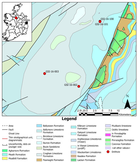
Figure 1.
A geological map showing the bedrock units in the study area and the location of the diamond drillholes discussed in the text.
In borehole GSI-16-101, the Ballymore Limestone Formation is represented by two contrasting facies: a lower interval and upper interval (1.5–14 m and 44–59.3 m), which consist of dark-grey, well-bedded, nodular, fine-grained, argillaceous, bioclastic limestone interbedded with black calcareous shale, and a middle interval (14–44 m) of light-grey, coarse-grained, bioclastic limestone.
The Oakport Limestone Formation consists of light-grey, massive, clean, coarse-grained, bioclastic limestone with two thick intervals of darker-grey, fine-grained, argillaceous limestone between 132–151 m and 219.5–245 m. The latter show bioturbation, chert nodules and occasional fenestral fabrics with pedogenic structures (e.g., rootlets). The top of the formation is placed at the incoming of darker-grey, coarser-grained limestone with chert nodules of the Ballymore Limestone Formation at 59.3 m [2].
The Kilbryan Limestone Formation consists of dark-grey, fine-grained, argillaceous, nodular, bioclastic limestone alternating with dark, calcareous mudstone, which is of a higher proportion in the lower part. Bioturbation can be intense in places. The upper boundary of the Kilbryan Limestone Formation and the contact with the overlying Oakport Limestone Formation at 297.2 m is sharp, with the incoming of massive, clean, light-grey, dolomitised limestone equivalents [2].
The distal lateral Waulsortian limestone facies in this hole is differentiated from the succeeding Kilbryan Limestone Formation by its higher proportion of limestone to mudstone and distinct, clean, nodular micrite patches. In this hole, a thick interval of clean, coarser-grained limestone is present, which is interpreted as a distal lateral equivalent to the Waulsortian [2].
The Ballysteen Formation in this comprises light-grey and dark-grey, fine-grained, argillaceous, nodular, bioclastic limestone alternating with black, calcareous and non-calcareous mudstone. The limestone is often bioturbated. The upper contact of the Ballysteen Formation with the overlying distal lateral Waulsortian limestone facies occurs at c.398 m [2,3].
The Moathill Formation comprises massive, light-grey, non-calcareous sandstone, dark-grey mudstone and thin, bioclastic limestone. The top of the Moathill Formation at 456 m marks a sharp boundary with the succeeding limestone-dominant Ballysteen Limestone Formation [2].
The Meath Formation comprises an alternation of calcareous, cross-bedded sandstones with rip-up clasts, siltstone and black, non-calcareous mudstone. The lower part of the formation has gypsum nodules and bands [2].
In this borehole, the Boyle Sandstone Formation comprises greenish-grey sandstone, with quartz pebbles and black-shale beds. The upper contact of the Boyle Sandstone Formation with the overlying Meath Formation at 500.9 m is sharp and defined by the presence of the first marine bed with corals [2].
3. Materials and Methods
Geological Survey Ireland maintains a SisuROCK core-scanning suite. The SWIR camera is manufactured by Specim, and it measures 288 bands from 985.64 nm to 2587.07 nm.
The drillhole was scanned box by box and the output files were processed using Python libraries: NumPy [14], Spectral Python [15] and elements of Hylite [4]. The raw data from each box were corrected to reflectance using white and dark references captured during each scan, hull-corrected [16] and denoised using a convex-hull quotient [16], which removes the background from the spectra and enables the easier identification of the features. The smoothed dataset was filtered with a Savitzky–Golay filter implementation in the SciPy library [17].
A mask in the shape of the core box is produced via a thresholded Pearson correlation coefficient between the continuum-removed spectrum and a continuum-removed example spectrum of the wooden core box. The image is clipped to the extent of the mask to remove the scanning table from the image. The mask for each box is visually examined to ensure that no core is masked, and that no extraneous material is left unmasked.
The chemical bonds present in a mineral can determine whether energy of different wavelengths is absorbed or reflected [7,8,9,10,11]. When energy is absorbed, the resulting reflectance spectrum will have absorption features: troughs of varying depths and wavelength positions determined via the mineral chemistry of the sample. For this study, the presence or absence of a feature in a particular wavelength range was determined using the Hylite absorption feature-finding algorithm [4]. This algorithm finds the n deepest features, noting that the larger the value of n, the more likely it is that features may be identified, which are only an effect of noise. For this study, we used n = 5, and if a feature was not found, then it was considered absent. This study used this minimum-wavelength-mapping technique, identifying local minima, to study the 2320 nm feature and the 2200 nm feature (Figure 2) [13].
The 2200 nm feature is diagnostic for a wide range of minerals: the kaolin group, muscovite, phengite, paragonite, tourmaline, jarosite and prehnite [18,19,20,21,22]. The most common position of this feature in the study dataset is at 2205 nm, which is in the area most associated with the kaolin group [18], although kaolinite absorptions must show a doublet feature, which this study did not test for. Some spectra display a feature around 2190 nm, which would be in the muscovite range [22]. The other minerals are unlikely to be present in these limestone rocks. The 2200 nm feature is interpreted here to represent argillaceous material, regardless of the specific mineral, as most minerals with diagnostic features in this range are di-octahedral sheet silicates.
The 2320–2345 nm feature is diagnostic for carbonate minerals [7,10,13]. The wavelength positions of this feature are affected by the replacement of Ca with Mg, Fe and/or Mn. Increasing concentrations of Mg and Fe push the position to shorter. Magnesium carbonates are more common in the Irish Carboniferous than iron carbonates; thus, we interpreted the wavelength position to indicate calcitic or dolomitic compositions of limestone.
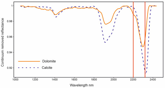

Figure 2.
Continuum-removed spectra of calcite and dolomite from the JPL ECOSTRESS library [23]. The 2320 nm and 2200 nm positions are displayed as red vertical lines.
The process for determining the wavelength position starts with running the absorption feature-finding algorithm through each pixel in the smoothed image. Each spectrum is inverted so that the absorption troughs can be treated as peaks, identifying the local minima. The smoothed image is used for the absorption feature-finding algorithm because noise in the reflectance dataset can cause the misidentification of a peak’s presence or absence. If there is no feature in the wavelength range of interest, then the pixel is masked out. If a feature is present in the smoothed dataset pixel, then the true wavelength position is calculated from the same pixel in the reflectance dataset. The continuum is removed for a specific wavelength range relevant to the feature, and the simple quadratic method [24] is used to calculate the true wavelength of the feature.
We can define hyperspectral facies by combining elements of the 2200 nm and 2320 nm features, using a decision tree classifier (Figure 3). These facies will be highly sensitive to carbonate and clay mineralogy. We developed 10 facies (Table 1) that we consider applicable to the Irish Carboniferous rocks based on the presence or absence of the 2200 nm feature and the wavelength position of the 2320 nm feature.
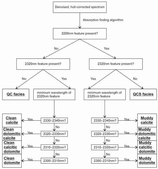
Figure 3.
Visualisation of the decision tree used to classify the hyperspectral facies.

Table 1.
Definition of the hyperspectral facies using the 2200 nm and 2320 nm absorption features.
In our dataset, the spatial pixel size is often larger than the grain size, which means that the recorded spectrum often represents a mixture of multiple grains, potentially multiple minerals. If the 2320 nm feature is present, then the pixel is clearly calcareous (contains carbonate minerals), but a spectrum containing both the 2320 nm feature and the 2200 nm feature is likely to be a mixture of carbonate minerals and argillaceous material.
The next step in assigning a pixel to a facies is to determine whether it is “clean” or “muddy”. In this context, we define the term muddy to mean that there is a presence of argillaceous material in the form of sheet silicates (mainly clay minerals), as opposed to clean, which means that argillaceous material is absent or is present in such small amounts that it does not produce a spectral response. The presence of a 2200 nm feature in a spectrum containing the 2320 nm feature defines it as muddy and spectra without a 2200 nm feature are clean.
Once a pixel is determined to be clean or muddy, the true wavelength position of the 2320 nm feature is calculated, and the facies is assigned using the values in Table 1.
The wavelength positions of carbonate absorption features in SWIR data have been shown to be unaffected by grain size variation [25,26]. For this reason, we consider it appropriate to use the wavelength position of the 2320 nm feature as part of the facies definition.
The final two facies we define apply to pixels that do not have a 2320 nm feature present. One interpretation of the absence of the 2320 nm feature is that the pixel is non-calcareous, and this is likely to be the case for the lowest sandstone units in the hole. However, the 2320 nm feature has been observed to be absent where the rock is known to be carbonaceous from thin sections or HCl reaction. We suggest that spectral quenching [25,27] resulting from the presence of organic material is obscuring the carbonate absorption signatures in these regions. Pixels with absent 2320 nm features are categorised into one of two facies, depending on the presence or absence of the 2200 nm feature.
A suite of 27 samples was collected from GSI-16-101, and thin sections were created for each to determine the age through micropaleontological analysis [2]. These samples were not collected as part of this project and so were subject to the usual sampling bias. The samples were collected based on their suitability to produce microfauna of good quality and quantity. However, the descriptions of the thin sections can be used to verify the spectral data. Five representative samples will be shown in detail, while the rest are tabulated in Supplementary Material Table S1.
An additional 10 samples were collected for this project, based on our hyperspectral results. As mentioned above, the location of each sample targeted apparent discrepancies between the original logged lithologies (as described in the log: Figure 4) and the HS results.
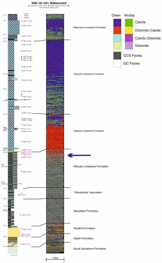
Figure 4.
Downhole details of GSI-16-101. First column is a graphic log and interpretation based on observation and micropalaeontology. The sample points are indicated, samples in red are those collected for this study. The distribution of the interpreted hyperspectral facies is shown on the right. The red lines indicate equivalent depths. The blue arrow shows the change in the sedimentation pattern across the Tournaisian/Viséan boundary.
To differentiate calcite and dolomite, one half of each thin section was treated with Potassium Hexacyanoferrate and Alizarin Red, as described in [28].
4. Results
The robustness of the hyperspectral facies classification was tested using the thin-section descriptions. Predicted hyperspectral facies were produced from the lithological characteristics of the thin sections and compared with the observed hyperspectral facies in the regions from which the thin sections were collected (Table 2). Of the 34 thin sections collected, 21 predicted facies matched or nearly matched the observed hyperspectral facies. Where the hyperspectral facies were observed to be quenched, this was never accurately predicted.

Table 2.
Tabulated sample information comparing hyperspectral facies predicted from thin-section descriptions with observed spectral facies in the region of the core where the thin section was taken.
As summarised above, lithologically, the Mississippian succession in the North-West Midlands represents a gradual change from terrestrial siliciclastic sediments at the base in the Tournaisian to fully open marine and basinal carbonates in the Viséan at the top. The change in sedimentation is diachronous across the carbonate ramp and driven by eustatic sea-level changes. In the lower Viséan time, the differentiation into deeper-water basinal regions and shallower-water shelf areas started to accelerate, resulting in structural “blocks” in the Irish North Midlands [2]. This change in the sedimentation pattern across the Tournaisian/Viséan boundary can be seen clearly in the HS responses of the boreholes studied. In borehole GSI-16-101, this change occurs in the upper part of the Kilbryan Limestone Formation, shown by the blue arrow in Figure 4.
In the following paragraphs, selected examples are given as a guide to the interpretation of the lithostratigraphic logs and HS facies logs.
4.1. Viséan (from MFZ 9 to MFZ 12)
4.1.1. Ballymore Limestone Formation
Sample MKP-16-180 was collected at 16.4 m within the Ballymore Limestone Formation (upper interval). This sample is a medium-grey, medium-grained, moderately sorted, bioclastic limestone.
The hyperspectral facies (HSF) image of the sample region (Figure 5) shows that it is dominated by clean calcite with a few scattered pixels of more dolomitic facies. The thin-section description confirms the lack of dolomitisation in this sample.
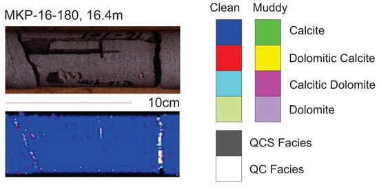
Figure 5.
RGB image of the region of the core the sample was collected from (top), the hyperspectral facies distribution in the same region (bottom) and the hyperspectral facies legend (right). Fractures in the core produce no response to a noisy response and should be disregarded. Sample region dominated by the clean calcite facies.
Hyperspectral facies log: The three intervals described in the stratigraphic log are clear in the hyperspectral facies distribution (Figure 4). The upper and lower intervals consist of quenched facies and muddy calcite facies, while the middle interval is dominated by clean calcite facies with small patches of clean dolomitic calcite and muddy dolomitic calcite.
4.1.2. Oakport Limestone Formation
Sample MKP-16-187 was collected at 113.6 m, in the clean part of the Oakport Limestone Formation.
The sample is dominated by clean calcite and dolomitic calcite facies (Figure 6). Interestingly, the dolomitisation is only visible in the thin section and is not apparent in the hand specimen. The white speckles indicate QC facies. These facies appear to increase in frequency downhole (arrow on sample points uphole) towards the fracture.
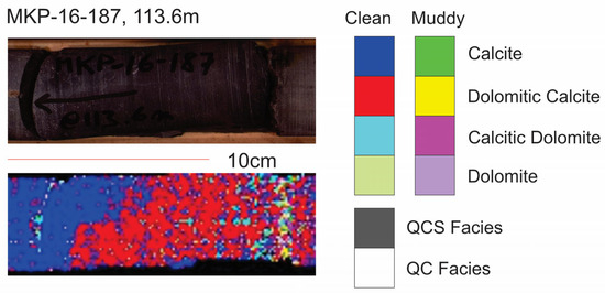
Figure 6.
RGB image of the region of the core the sample was collected from (top), the hyperspectral facies distribution in the same region (bottom) and the hyperspectral facies legend (right). Fractures in the core produce no response to a noisy response and should be disregarded. Sample region changes from clean dolomitic calcite facies to clean calcite facies from right to left.
Sample MKP-16-512 was collected at 293.2 m in clean limestone near the base of the Oakport Limestone Formation. The core at this sample point is noted in the logs as being dolomitised. In the thin section, the lithology consists of a fine–medium-grained, moderately sorted, crystalline dolomite with small cavities filled with some late-diagenetic calcite crystals.
The sample region (Figure 7) shows a strong blue colour, indicating clean dolomitic calcite facies with only a few pixels of QC facies.
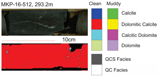
Figure 7.
RGB image of the region of the core the sample was collected from (top), the hyperspectral facies distribution in the same region (bottom) and the hyperspectral facies legend (right). Fractures in the core produce no response to a noisy response and should be disregarded. Sample region is dominated by the clean dolomitic calcite facies.
Hyperspectral facies log: The formation is dominated by the clean calcite facies at the top (from 59 m to 132 m), with short intervals of clean dolomitic calcite. The two thick intervals of darker, argillaceous limestone are shown in the hyperspectral facies distribution to be a continuous interval with a high proportion of muddy dolomitic calcite facies with small sections of clean calcite facies (Figure 4). The lowest part of the formation is logged as the Kilbryan/Oakport Formation and is dominated by clean dolomitic calcite facies. The top of the formation is dominated by the clean calcite facies.
4.2. Tournaisian (from MFZ 1 to MFZ 8)
As can be seen in Figure 4, the differentiation of various facies becomes more subtle (at this scale) in the Tournaisian (below the blue arrow in Figure 4). This is the result of the increasing heterogeneity of the geology and small-scale variations in the proportions of carbonate, non-carbonate, argillaceous, evaporitic and organic components, and it marks a fundamental shift in the sedimentation environment from the larger homogenous regions in the overlying units.
4.2.1. Kilbryan Limestone Formation
Hyperspectral facies log: The lower part of this unit is dominated by the QCS facies with disseminations of clean calcite, muddy calcite and muddy dolomitic calcite, probably representing veins and bioclasts (Figure 4). Towards the top of the unit, the QCS facies is interbedded with clean calcitic dolomite intervals, which become dolomitic calcite facies towards the top (Figure 8).

Figure 8.
High-resolution RGB image (top) and spectral facies distribution (bottom) of box 72, 300.8–305 m, in the Kilbryan Formation, showing interbedding between the quenched facies and the clean dolomitic calcite facies.
4.2.2. Distal Lateral Waulsortian Limestone Facies
Hyperspectral facies log: This unit is dominated by the QCS facies but has 30–40% small intervals of clean calcite and muddy calcite facies (Figure 4).
4.2.3. Ballysteen Formation
Sample MKP-16-516 was collected at 431.1 m, in the Ballysteen Limestone Formation. In the thin section and hand specimen, the sample is described as a fine-grained, poorly sorted, bioclastic limestone. There are shale bands present throughout the unit, as well as organic material. Detrital quartz was identified in the thin section.
The hyperspectral facies in the sample region is dominated by QCS facies, with pixels of QC, muddy calcite and clean calcite facies (Figure 9).
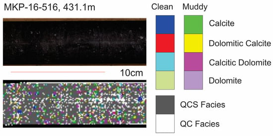
Figure 9.
RGB image of the region of the core the sample was collected from (top), the hyperspectral facies distribution in the same region (bottom) and the hyperspectral facies legend (right). Fractures in the core produce no response to a noisy response and should be disregarded. The HS facies of this sample is dominated by the QCS facies (grey) with patches of the muddy calcite and muddy dolomitic calcite facies (green). There are also scattered pixels showing QC facies (white).
Hyperspectral facies log: In this hole, the formation is dominated by the QCS facies with dispersed and almost pixel-scale regions of muddy calcite and dolomitic calcite facies (Figure 4). There are numerous small regions of clean calcite, which represent veins and bioclasts (Figure 10). More detail can be seen at a larger scale.
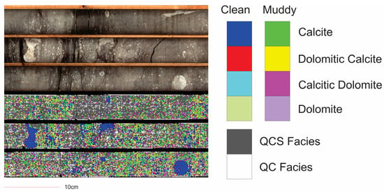
Figure 10.
High-resolution RGB image (top) and spectral facies distribution of box 108, 452.3–456.65 m, in the Ballysteen Limestone Formation. The clean calcite facies (dark-blue colour) pick out bioclasts and regions of calcite replacement.
4.2.4. Moathill Formation
Sample MKP-23-20 was collected at 475.4 m in the Moathill Formation. In the hand specimen, the core is a fine–medium-grained, beige-coloured sandstone. In the thin section, it consists of sandstone–arkose, with a carbonate matrix between the quartz and feldspar grains. A late interstitial dolomite appears to etch the quartz grain boundaries. High Fe+ content is indicated by the staining. Organic material is present.
In Figure 11, muddy dolomitic calcite and calcitic dolomite facies dominate. Small patches of QCS facies are scattered throughout but increase uphole (to the left) before dominating the facies. This sample is interpreted to show the late-stage dolomitisation of an argillaceous rock.
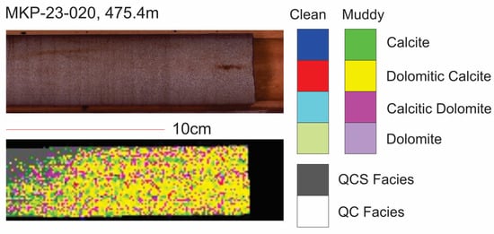
Figure 11.
RGB image of the region of the core the sample was collected from (top), the hyperspectral facies distribution in the same region (bottom) and the hyperspectral facies legend (right). Fractures in the core produce no response to a noisy response and should be disregarded. Sample region is dominated by the muddy dolomitic calcite facies.
Hyperspectral facies log: The base of the formation consists of the metre-scale interbedding of the QCS facies with muddy or clean dolomitic calcite facies. The top of the formation consists of centimetre-scale interbeds of clean dolomitic calcite facies with QCS facies, and some interbeds of clean calcite facies (Figure 4).
4.2.5. Meath Formation
Hyperspectral facies log: This formation is dominated by the QCS facies with intervals up to 1 m of muddy calcite facies and thin intervals of clean dolomitic calcite facies (Figure 4).
4.2.6. Boyle Sandstone Formation
Hyperspectral facies log: In this hole, the formation is dominated by the QCS and QC facies with thin intervals of clean or muddy dolomitic calcite facies (Figure 4).
5. Discussion and Synthesis
5.1. Interpretation
We note that the match between the predicted facies from the thin-section descriptions and the observed hyperspectral facies is not perfect. It has proven particularly difficult to predict quenched facies from thin sections, and we attribute much of this to the sampling bias used for most of our thin sections—the sampling of the cleanest intervals. Where other predictions failed, we attribute this to comparing a prediction from a small and possibly non-representative sample in this section to the dominant lithology across a heterogenous area.
We find that there exists a good and easily recognisable correlation between the litho- and biostratigraphic units and their HS facies signatures in the Irish North Midlands region. The depth of the lithological boundaries does not perfectly align with clear changes in the hyperspectral facies. We interpret this as a result of the uncertainty in defining a precise boundary at a specific depth in a gradually changing lithology and the bias caused by different workers. This bias is enhanced by the lack of clearly defined stratigraphic boundaries for most of the formations in the literature. Despite the increased volume of non-carbonate and organic material in the Tournaisian, the HS imagery allows for the quick and easy differentiation of carbonate facies within the whole succession, and more subtle variations can be seen in the Tournaisian. HS facies mapping can help to illustrate the arbitrary nature of unit boundaries by showing clearly—and more precisely—the subtle changes in the lithological composition across these boundaries.
5.2. Regional Correlation
Following the detailed study of the hyperspectral facies distribution in drillhole GSI-16-101, the same techniques were applied to three other holes in the same fault block (Figure 1), which each had equally well-constrained litho- and biostratigraphic units. These boreholes are GSI-16-002 (Castlemine), GSI-16-003 (Carrowreagh) and GSI-16-100 (Hillstreet 1). Hillstreet 2 was drilled at a c.20 m distance from Hillstreet 1, due to technical problems at the Hillstreet 1 location. The Carrowreagh borehole shows a condensed succession in the western part of the fault block. This is attributed to its position higher up on the shelf, in a shallower-water environment. The Castlemine borehole was drilled in the footwall of the Strokestown Fault, the bounding fault with the Lower Palaeozoic Inlier to the east.
As shown in Figure 12, two different lithofacies are recognised in the Ballymore Limestone Formation (MFZ 11). These two lithofacies can be recognised in the HS facies with clean dolomitic calcite facies separating upper and lower muddy calcite facies. The same facies distribution can be seen in boreholes GSI-16-100 (Hillstreet 1) and GSI-16-003 (Carrowreagh). In borehole GSI-16-002 (Castlemine), the borehole is collared in the middle clean calcite facies.
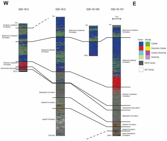
Figure 12.
Fence diagram of the hyperspectral facies distribution in four holes. The tie lines represent the geological and micropalaeontological interpretation independent of the hyperspectral.
The Oakport Limestone Formation (MFZ 9 and MFZ 10) shows a similar triple partition in boreholes GSI-16-101, GSI-16-002 and GSI-16-003. The upper and lower parts consist of pale-grey, fine-grained, well-sorted, bioclastic limestone, and the middle part consists of dark-grey, fine-grained, massive limestone. This division can be seen in the HS response. A muddy calcite/dolomite facies separates upper and lower clean calcite/dolomitic calcite facies. In borehole GSI-16-100, Hillstreet 1, only the upper unit was drilled.
The Kilbryan Limestone Formation (MFZ 8) shows a muddy dolomitic calcite facies with QCS facies in boreholes GSI-16-101 and GSI-16-002. In borehole GSI-16-003, Carrowreagh, the Kilbryan Limestone Formation comprises c.20 m of dolomitised, dark-grey, fine-grained, argillaceous limestone. The HS response shows a dominantly clean dolomitic calcite–clean dolomitic calcite facies. Although dolomitic in all three boreholes, the cleaner limestone in the Carrowreagh borehole was drilled higher up on the shelf, with less “mud” input from the tectonic high east of the Strokestown Fault.
The limestone interpreted as distal Waulsortian facies (MFZ 8) is distinct by its litho-facies. In borehole GSI-16-003, Carrowreagh, this consists of pale-grey, medium-grained, moderately sorted, bioclastic limestone with argillaceous seams and stylolites. In the boreholes Hillstreet and Castlemine, the lithology also includes evaporites and a higher proportion of mud (argillaceous) in the limestone. In the HS response, this lateral variation is well defined, whereas in traditional core logging, it is in fact difficult to notice.
The other Tournaisian units (from MFZ 8 to MFZ 3/4), the Ballysteen Limestone Formation, Moathill Formation, Meath Formation and at least parts of the Boyle Sandstone Formation, comprise various lithologies, which all merge into a very heterogenous HS response in the correlation diagram (Figure 12). However, this is a function of the scale at which this figure can be shown here. Much more detail can be retrieved from the HS imagery at higher resolution. The most noticeable feature in the HS response can be seen in the Castlemine borehole in the Moathill Formation, with a high proportion of QC facies (white).
To summarise, a transition in the facies distribution from west to east can be seen in these four holes. The Ballymore Limestone Formation consists of intercalations of muddy and clean calcite facies, but the pattern is not consistent between holes, suggesting that these facies are not laterally continuous. The Oakport Limestone Formation becomes thicker from west to east, but it consistently has clean calcite facies at the top and base of the unit, with a region of muddy calcite facies in the centre. The muddy calcite centre becomes more quenched towards the east, and the lower clean region is more dolomitic in the east. The Kilbryan is dominantly clean dolomitic calcite in the west but transitions to dominantly quenched facies with small intervals of clean calcite facies becoming smaller further east. The distal Waulsortian facies interval is clean in the west, both calcite and dolomitic calcite facies, but it transitions eastward into mixed quenched and muddy calcite facies.
5.3. Discussion
This study has shown that hyperspectral facies analysis applied to drill cores can identify lithological variations in composition in the carbonate/muddy carbonate/non-carbonate range. This can be used for accurate and much more detailed descriptions of the lithologies of calcareous drill cores. Because every pixel is treated the same way, the analysis itself is objective and overcomes subjective bias from traditional approaches.
The HS facies we defined broadly agree with the thin-section interpretations of the lithologies, and where they do not, the lithologies are quite variable, and a thin section taken nearby would also likely have a different interpretation.
Most interestingly, the hyperspectral facies can pick out details over a broad scale that are only otherwise apparent in the thin section.
The HS facies are highly biased towards the mineralogy of the geological materials, and other lithological features that are usually used in defining lithological facies, such as grain size, texture, fossils and bioclasts, will not have significant impacts on the hyperspectral facies classification.
While not a replacement for a lithological log by an experienced geologist, hyperspectral facies can make an excellent first-pass interpretation of a hole and will be useful to a geologist before, during and after lithological logging.
A hole can be processed using these techniques relatively quickly; thus, hyperspectral facies analysis will lend itself well to regional correlations across multiple holes with specific questions followed up on with a lithological log.
The technique could be enhanced by extending the decision tree to include features extracted from other spectral ranges, which has the potential to overcome spectral quenching or improve the identification of iron carbonates. The technique could also be adapted to produce automated correlations between multiple holes, which would be of great benefit for exploration activities in mature, data-rich prosect areas.
Supplementary Materials
The following supporting information can be downloaded at https://www.mdpi.com/article/10.3390/geosciences13120381/s1, Table S1: Tabulated sample information comparing thin-section descriptions with spectral facies.
Author Contributions
Conceptualization, R.R. and M.P.; methodology, R.R. and M.P.; software, R.R.; writing—original draft preparation, R.R.; writing—review and editing, M.P. All authors have read and agreed to the published version of the manuscript.
Funding
This research received no external funding.
Data Availability Statement
Hyperspectral images are available free of charge from Geological Survey Ireland, and thin sections may be viewed by appointment. Please contact the corresponding author.
Acknowledgments
This research article is published with the permission of the Director of Geological Survey Ireland.
Conflicts of Interest
The authors declare no conflict of interest.
References
- Manifold, L. The Anatomy of a Mississippian (Viséan) carbonate platform interior, UK: Depositional cycles, glacioeaustacy and facies mosaics. Sediment. Geol. 2020, 401, 105633. [Google Scholar] [CrossRef]
- Pracht, M.; Somerville, I.D. A revised Mississippian lithostratigraphy of County Galway (western Ireland) with an analysis of carbonate lithofacies, biostratigraphy, depositional environments and palaeogeographic reconstructions utilising new borehole data. J. Palaeogeogr. 2015, 4, 1–26. [Google Scholar] [CrossRef]
- Pracht, M.; Somerville, I.D.; Rogers, R. North Midlands Block 1:50,000 Bedrock Data Package. 2021. Available online: https://www.gsi.ie/en-ie/data-and-maps/Pages/Bedrock.aspx#50k (accessed on 12 February 2023).
- Thiele, S.T.; Lorenz, S.; Kirsch, M.; Acosta, I.; Tusa, L.; Hermann, E.; Mockel, R.; Gloaguen, R. Multi-scale, multi-sensor data integration for automated 3-D geological mapping. Ore Geol. Rev. 2021, 136, 104–252. [Google Scholar] [CrossRef]
- De La Rosa, R.; Khodadadzadeh, M.; Tusa, L.; Kirsch, M.; Gisbert, G.; Tornos, F.; Tolosana-Delgado, R.; Gloaguen, R. Mineral quantification at deposit scale using drill-core hyperspectral data: A case study in the Iberian Pyrite Belt. Ore Geol. Rev. 2021, 139, 104514. [Google Scholar] [CrossRef]
- Lypaczewski, P.; Rivard, B.; Lesage, G.; Byrne, K.; D’Angelo, M.; Lee, R.G. Characterisation of mineralogy in the highland valley porphyry cu district using hyperspectral imaging, and potential applications. Minerals 2020, 10, 473. [Google Scholar] [CrossRef]
- Hunt, G.; Salisbury, J. Visible and near infrared spectra of minerals and rocks. I. Silicate minerals. II. Carbonates. Mod. Geol. 1971, 1, 283–300. [Google Scholar]
- Hunt, G. Spectral signatures of particulate minerals in the visible and near infrared. Geophysics 1977, 42, 501–513. [Google Scholar] [CrossRef]
- Crowley, J.K. Visible and near-infrared spectra of carbonate rocks: Reflectance variations related to petrographic texture and impurities. J. Geophys. Res. Solid Earth 1986, 91, 5001–5012. [Google Scholar] [CrossRef]
- Gaffey, S.J. Spectral reflectance of carbonate minerals in the visible and near infrared (0.35–2.55 microns): Calcite, aragonite, and dolomite. Am. Mineral. 1986, 71, 51–162. [Google Scholar]
- Clark, R.; Gallagher, A.; Swayze, G. Material absorption band depth mapping of imaging spectrometer data using the complete band shape leastsquares algorithm simultaneously fit to multiple spectral features from multiple materials. In Proceedings of the Third Airborne Visible/Infrared Imaging Spectrometer (AVIRIS) Workshop, Pasadena, CA, USA, 4–5 June 1990; JPL Publication No. 90–54. Jet Propulsion: Pasadena, CA, USA, 1990; pp. 176–186. [Google Scholar]
- Baissa, R.; Labbassi, K.; Launeau, P.; Gaudin, A.; Ouajhain, B. Using HySpex SWIR-320m hyperspectral data for the identification and mapping of minerals in hand specimens of carbonate rocks from the Ankloute Formation (Agadir Basin, Western Morocco). J. Afr. Earth Sci. 2011, 61, 1–9. [Google Scholar] [CrossRef]
- Laukamp, C.; Rodger, A.; LeGras, M.; Lampinen, H.; Lau, I.; Pejcic, B.; Stromberg, J.; Francis, N.; Ramanaidou, E. Mineral Physicochemistry Underlying Feature-Based Extraction of Mineral Abundance and Composition from Shortwave, Mid and Thermal Infrared Reflectance Spectra. Minerals 2021, 11, 347. [Google Scholar] [CrossRef]
- Harris, C.; Millman, K.J.; van der Walt, S.J.; Gommers, R.; Virtanen, P.; Cournapeau, D.; Wieser, E.; Taylor, J.; Berg, S.; Smith, N.J.; et al. Array programming with NumPy. Nature 2020, 585, 357–362. [Google Scholar] [CrossRef] [PubMed]
- Boggs, T. Spectral Python (SPy). 2014. Available online: https://www.spectralpython.net/ (accessed on 12 February 2023).
- Clark, R.; Roush, T. Reflectance Spectroscopy: Quantitative Analysis Techniques for Remote Sensing Applications. J. Geophys. Res. Solid Earth 1984, 89, 6329–6340. [Google Scholar] [CrossRef]
- Virtanen, P.; Gommers, R.; Oliphant, T.; Haberland, M.; Reddy, T.; Cournapeau, D.; Burovski, E.; Peterson, P.; Weckesser, W.; Bright, J.; et al. SciPy 1.0: Fundamental algorithms for scientific computing in python. Nat. Methods 2020, 17, 261–272. [Google Scholar] [CrossRef] [PubMed]
- Frost, R.; Johansson, U. Combination Bands in the Infrared Spectroscopy of Kaolins—A Drift Spectroscopic Study. Clays Clay Miner. 1998, 46, 466–477. [Google Scholar] [CrossRef]
- Reddy, B.; Frost, R.; Martens, W.; Wain, D.; Kloprogge, J. Spectroscopic Characterization of Mn-Rich Tourmalines. Vib. Spectrosc. 2007, 44, 42–49. [Google Scholar] [CrossRef]
- Bishop, J.; Murad, E. The Visible and Infrared Spectral Properties of Jarosite and Alunite. Am. Mineral. 2005, 90, 1100–1107. [Google Scholar] [CrossRef]
- White, A.; Laukamp, C.; Stokes, M.; Legras, M.; Pejcic, B. Vibrational Spectroscopy of Epidote, Pumpellyite and Prehnite Applied to Low-Grade Regional Metabasites. Geochem. Explor. Environ. Anal. 2017, 17, 315–333. [Google Scholar] [CrossRef]
- Vedder, W.; McDonald, R. Vibrations of the OH Ions in Muscovite. J. Chem. Phys. 1963, 38, 1583–1590. [Google Scholar] [CrossRef]
- Meerdink, S.; Hook, S.; Roberts, D.; Abbott, E. The ECOSTRESS spectral library version 1.0. Remote Sens. Environ. 2019, 230, 111196. [Google Scholar] [CrossRef]
- Rodger, A.; Laukamp, C.; Haest, M.; Cudahy, T. A Simple Quadratic Method of Absorption Feature Wavelength Estimation in Continuum Removed Spectra. Remote Sens. Environ. 2012, 118, 273–283. [Google Scholar] [CrossRef]
- Vandermeer, F. Spectral reflectance of carbonate mineral mixtures and bidirectional reflectance theory: Quantitative analysis techniques for application in remote sensing. Remote Sens. Rev. 1995, 13, 67–94. [Google Scholar] [CrossRef]
- Zaini, N.; van der Meer, F.; van der Werff, H. Effect of Grain Size and Mineral Mixing on Carbonate Absorption Features in the SWIR and TIR Wavelength Regions. Remote Sens. 2012, 4, 987–1003. [Google Scholar] [CrossRef]
- Clark, R.N. Chapter 1: Spectroscopy of Rocks and Minerals, and Principles of Spectroscopy. In Manual of Remote Sensing, Volume 3, Remote Sensing for the Earth Sciences; Rencz, A.N., Ed.; John Wiley and Sons: New York, NY, USA, 1999; pp. 3–58. [Google Scholar]
- Füchtbauer, H. Sedimente und Sedimentgesteine; Schweizerbart: Stuttgart, Germany, 1988; 1141p. [Google Scholar]
Disclaimer/Publisher’s Note: The statements, opinions and data contained in all publications are solely those of the individual author(s) and contributor(s) and not of MDPI and/or the editor(s). MDPI and/or the editor(s) disclaim responsibility for any injury to people or property resulting from any ideas, methods, instructions or products referred to in the content. |
© 2023 by the authors. Licensee MDPI, Basel, Switzerland. This article is an open access article distributed under the terms and conditions of the Creative Commons Attribution (CC BY) license (https://creativecommons.org/licenses/by/4.0/).