Abstract
Earth flows are complex geological processes that, when interacting with linear infrastructures, have the potential to cause significant damage. Consequently, conducting comprehensive investigations and continuous monitoring are becoming paramount in designing effective mitigation measures and ensuring sustainable risk management practices. The use of digital image correlation (DIC) algorithms for the displacement monitoring of earth flows is a relatively new and growing field with a limited number of dedicated works in the literature. Within this framework, the present paper contributes by evaluating DIC techniques at several earth flow sites. These assessments were founded upon data obtained from both low-cost and multi-platform sensors, used to assess the displacement field, pinpointing the most active sectors, and gauging their rates of movement during different kinematic phases. In this regard, the highest localized movement velocities reached in the Pietrafitta (0.01 m/day) and Grillo (0.63 m/day) earth flows experience different ongoing kinematic processes. The versatility of these techniques is notable, manifesting in the ease of installation, cost-effectiveness, and adaptability to various platforms. The proven reliability in terms of maximum accuracy (1 pixel) and sensitivity (0.05 m) lays the foundation for the extensive use of the presented techniques. The amalgamation of these attributes positions DIC techniques as competitive, adaptable, and readily deployable tools in earth flow studies.
1. Introduction
Earth flows predominantly occur within clayey and structurally complex formations [1,2,3,4,5,6,7]. When they interact with human-made structures, they can cause substantial damage. This holds particularly true with linear infrastructures like highways, railways, and pipelines crossing inhabited hilly regions such as the Italian Apennines [8]. Implementing mitigation and stabilization measures is often challenging due to their typical rheological and mechanical behaviors and their complex kinematics [9]. In this context, investigation and monitoring activities play a pivotal role in designing effective mitigation strategies and, consequently, in sustainable risk management [10,11,12]. Despite this, only a few works in the literature focused on the critical evaluation of both conventional and innovative techniques for earth flow monitoring. As an example, the authors of [13] studied the geomorphological evolution of earth flow through a combination of monitoring techniques such as visual interpretation of aerial and satellite imagery, quantitative analysis of digital elevation models (DEMs), and three-dimensional topographic measurements using robotic total stations (RTSs). Also, the authors of [14] employed a Ground-Based Interferometric Synthetic Aperture Radar (GB-InSAR) for risk management associated with an earth flow reactivation. Instead, the authors of [15] compared and combined data collected during different earth flow phases that occurred in 2016 in the site of Pietrafitta using different ground-based remote sensors such as RTS, GB-InSAR, and Terrestrial Laser Scanners (TLSs), with the aim to derive insights into the performance of such techniques. In addition, the authors of [16] demonstrated the applicability of using global positioning system (GPS) techniques to determine the 3D coordinates of the moving points of an earth flow precisely.
This scarcity may stem from the need to integrate multiple sensors to monitor the various factors influencing these complex processes, along with cost issues [17]. Although imaging techniques possess considerable potential benefits, the monitoring of earth flows near linear infrastructures remains a relatively nascent and evolving field, even in common practice. In recent years, some analyses based on digital image correlation (DIC) algorithms have been successfully employed for landslide assessment and monitoring [18,19,20,21,22,23,24,25,26,27,28,29,30], as well as for many other applications in geosciences [31]. Applying these techniques requires careful consideration of several factors, including selecting appropriate processing algorithms, data calibration and validation, and integrating different data types. Furthermore, interpreting DIC data requires specialized knowledge and skills in the field of engineering geology. Given the complexities involved, comprehensively studying landslides is challenging and requires accurate imaging and modeling over time [32,33]. As indicated in [34], its overarching purpose is a pivotal determinant of the success of geotechnical monitoring. Three main monitoring categories are pertinent: knowledge monitoring, control monitoringand emergency monitoring. These classifications can greatly assist in managing earth flow risk related to the presence of linear infrastructures. In all the aforementioned monitoring categories, DIC techniques are nowadays able to provide reliable data quickly, and, in specific cases, they can underpin the establishment of early warning systems (emergency monitoring) [35]. Such monitoring data can serve early warning purposes by identifying, for instance, displacement thresholds.
The overall objective of this work is to understand how modern digital image correlation (DIC) techniques can be utilized for the knowledge, control and emergency monitoring of earth flows while also conducting an assessment and comparison with more conventional monitoring techniques.
This study aims to present three examples of DIC monitoring applications on two distinct case studies, namely the Pietrafitta and Grillo earth flows, during three different timeframes. For these studies, images were acquired from three different platforms (a ground-based camera for Pietrafitta and UAV and satellite images for Grillo) during specific periods of heightened earth flow activity.
However, unlike other methodologies, DIC analysis carried out with satellite images was only used for long-term cognitive monitoring in the absence of ancillary data. The specific objectives are as follows:
- Evaluate the monitoring capabilities of the DIC technique at the Pietrafitta earth flow pilot site using low-cost ground-based sensors;
- Assess the monitoring capabilities of the DIC technique at the Grillo earth flow pilot site using sensors installed on UAV platforms;
- Perform a quantitative comparison with two classical monitoring techniques used at the pilot sites: the robotic total station survey (RTS) for Pietrafitta and the global navigation satellite system (GNSS) for Grillo. This comparison will focus particularly on displacement field assessment, identifying the most active sectors, and measuring motion rates during various phases of the earth flow.
2. Case Study Sites
This section presents the study sites characterized by the presence of slope instabilities and strategic road infrastructures. Activities were carried out at two landslide sites within the Campania Region (Italy), known as Pietrafitta and Grillo, situated in the provinces of Benevento and Avellino, respectively (Figure 1a). Both landslides can be classified as earth flows according to the well-known classification in [36], owing to their characteristic slow-moving and intermittent nature and the material involved. They mobilize clay-rich flysch formations (late Cretaceous–Miocene), which are widespread in the southern Apennines [1].
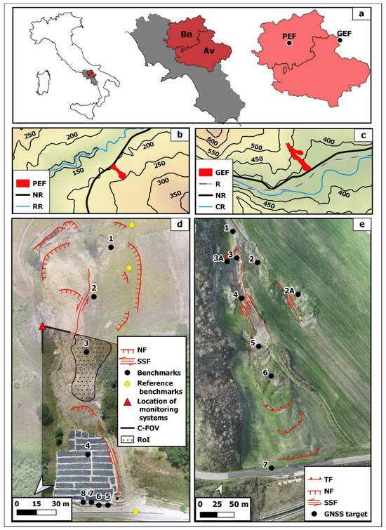
Figure 1.
(a) General overview and location of the earth flow study site. The Pietrafitta and Grillo earth flows are shown, with their topographical setting in (b,d) and orthophotos in (c,e), respectively. PEF: Pietrafitta earth flow, GEF: Grillo earth flow, NR: national road; RR: Reventa River; R: railway; CR: Cervaro River; TF: thrust fault; NF: normal fault; SSF: strike–slip fault; C-FOV: camera field of view; RoI: region of interest.
2.1. Pietrafitta Earth Flow
The Pietrafitta earth flow (41°13′13″ N, 14°44′33″ E) develops along the north-western slope of the Torre Palazzo hill, situated at elevations ranging from 200 to 250 m a.s.l., on the southern side of the Reventa River Valley, with an average slope angle of about 16° (Figure 1b–d). The earth flow is located within an overthrust fault zone between the Flysch Rosso formation (FYR) and the Fragneto Monforte formation (UFM). These geological sequences consist of a complex alternation of clay, sandstone, and calcareous marl levels. The entire extent of the earth flow spans approximately 250 m, with a width varying from approximately 30 m at the middle channel to around 100 m at both the source and depositional areas. Overall, it covers an area of about 10,000 m2; the estimated thickness of the material involved is between 2 and 5 m. The volume mobilized during various reactivation events is estimated at around 300,000 m3. Its active bulging toe has repeatedly affected a segment of the national road SS87, leading to several issues related to road asset management. The periods of greatest activity were in 2015 and 2016, which led to the complete closure of the road. From November 2016 to July 2017, some provisional works were carried out to mitigate the geomorphological risk. In particular, the earth flow toe was covered with a waterproof sheet, and a drainage trench was dug at the middle of the slope. However, an intensive rainfall period—exacerbated by a rapid snow-melting event—led at the beginning of March 2018 to the earth flow reactivation affecting more than half of the slope. The rainfall period is well evidenced by rainfall data collected at the “Torrecuso” rain gauge, managed by the Centro Agrometeorologico Regionale (C.A.R.) of the Campania Region, located 3 km west and at the same elevation as the Pietrafitta earth flow (Figure 2).
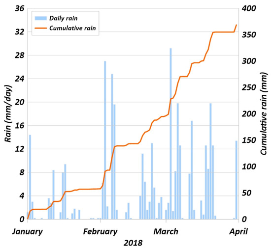
Figure 2.
“Torrecuso” rain gauge pluviogram.
Pietrafitta’s earth flow has been the subject of specific studies, including the work [15], which aimed to study the process through remote sensing instruments and a multi-sensor approach. The work carried out by the authors of [15] took into consideration the period of activity in 2016, exploiting different monitoring systems installed along the slope and combining the results of the different technologies. Due to this approach, the authors were able to fully understand the deformative behavior of earth flow in Pietrafitta, and the work presented here has taken advantage of this knowledge to study the period of activity in March 2018.
2.2. Grillo Earth Flow
The Grillo earth flow (41°14′32″ N, 15°15′51″ E) is located along the southwestern slope at elevations ranging from 350 to 500 m a.s.l, on the northern side of the Cervaro River Valley (Figure 1c–e), involving the Flysch of Faeto formation (FAE) terrain [37], which crops out with a calcareous–clayey–marly member. The Flysch of Faeto is highly fractured, and many springs, which are typically controlled by a local permeability contrast between clayey and fractured strata, are widespread in the area, especially in the upper part of the slope [38]. The earth flow body exhibits a stream bed incision that remains wet for a significant portion of the year. Two active branches depart from the source area of the earth flow, with one of them being notably more pronounced, featuring a 130-m-long transport zone and a fan-shaped, bulging toe. Different from the transport and deposition zone—where thrust and strike–slip faults are dominant—the source area is characterized by the presence of normal faults (Figure 3). In total, the Grillo earth flow covers an area of approximately 20,000 m2 and is located in the proximity of the well-known Montaguto earth flow [13,38,39]. This latter earth flow has experienced multiple reactivations over the years, resulting in severe damage and disruptions to both the SS90 national road and the strategic railway line connecting the Benevento and Foggia towns [38]. Similarly, the Grillo earth flow affects the same linear infrastructures. During the monitoring campaign, rainfall data were collected from April 2022 to June 2023 at the “Orsara di Puglia” rain gauge, managed by the local Civil Protection. Currently, the SS90 national road has been subjected to deformation due to the pressure exerted by the earth flow toe, whereas the railway line is presently safeguarded through the implementation of structural mitigation works. These measures include the construction of pile bulkheads and retaining walls (Figure 1e).
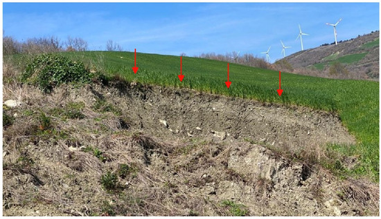
Figure 3.
The red arrows highlight the segment of the main scarp generated by the presence of a normal fault-like structure.
3. Materials and Methods
This chapter presents the remote sensing instruments (Section 3.1) in terms of sensors and platforms used in this study, as well as the techniques for data processing (Section 3.2) [40].
The main tools used in the processing phases were the IRIS software (version 1.17) [20], developed by NHAZCA S.r.l., for coregistration, multi-master, single-pair DIC analysis, and generation of displacement maps and time series; the Agisoft Metashape (version 1.7.6) software for the structure from motion (SfM) photogrammetric processing of an unmanned aerial system (UAS) imagery; and the QGIS software (version 3.10.8) for digital surface model (DSM) generation, computation of hillshades, and for all spatial analyses.
3.1. Remote Sensing Instruments and Data
In this study, monitoring instruments and available data were selected based on their functional properties to ensure efficient performance in terms of spatial, radiometric, spectral, and temporal resolution.
With reference to the Pietrafitta earth flow, the initial integrated monitoring system described by [15] was removed and only partially reactivated—with a different configuration—in July 2017 (Figure 4a). Specifically, a ground-based rugged camera (72 × 300 mm in size) equipped with a 1/2.9″ progressive CMOS low-resolution sensor (2MP) and a 3.6 mm focal length was securely installed on a stable pole situated on the left flank of the earth flow (Figure 4b,c). Additionally, the Robotic Total Station (Topcon mod. PS-101)—previously located on the opposite slope [15]—was positioned on the right flank of the earth flow, looking at 11 reflectors strategically placed along the slope for location (Figure 1d). The R-TS acquired data with a minimum resolution/accuracy of 1″. While the installation of these monitoring instruments—as already mentioned—occurred in July 2017, our data analysis was primarily centered on data acquired in March 2018. This timeframe coincided with the landslide reactivation. The data obtained from the RTS were compared with those derived from the DIC analysis to evaluate the reliability of the technique. We employed the well-established Pearson correlation method for this comparative analysis [41].
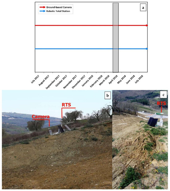
Figure 4.
(a) Timeline of the new monitoring system. The shaded grey box represents the timeframe analyzed. (b) Location of the ground-based camera and RTS captured from the opposite flank of the earth flow. (c) Location of RTS looking downhill.
Regarding the employment of an UAS for the Grillo earth flow study, we used a DJI Phantom 4 coupled with a D-RTK2 mobile station. This drone was equipped with a 1-inch CMOS sensor (20 megapixels) and a 24 mm focal length. The Real-Time Kinematics (RTK) system exhibited a remarkable positioning accuracy of 2 cm + 1 part per million (ppm) in both the vertical and horizontal dimensions. For georeferencing targets and monitoring activities within the Grillo earth flow area, we employed an RTK-capable GNSS receiver (Topcon model HiPer SR) with 3.5 mm + 0.4 ppm and 3.0 mm + 0.1 ppm vertical and horizontal precision, respectively. The data were acquired during a monitoring campaign that started in April 2022 through multi-temporal UAS and GNSS acquisitions in RTK mode using self-made targets (Figure 5). Table 1 presents a synopsis of the surveys performed, offering a comprehensive summary of the acquired dataset.
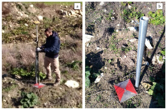
Figure 5.
(a) An operator during GNSS-RTK data collection. (b) A self-made GNSS target.

Table 1.
Timing of the multi-temporal UAS and GNSS surveys performed at the Grillo earth flow.
Furthermore, with the aim of observing how the phenomenon evolved over a longer period, Google® satellite imagery was used to perform a DIC analysis on the Grillo earth flow. A summary of the dataset is shown in Table 2.

Table 2.
Dataset for the satellite DIC analysis at Grillo earth flow.
Table 3 summarizes the characteristics of the monitoring platforms from which the data for the DIC technique were acquired.

Table 3.
Summary of the imaging platforms used for the DIC technique.
3.2. Imaging Techniques for Data Processing
For each study site, separate processing chains were created for the DIC techniques. To enhance clarity, these processing chains have been categorized into three main stages: pre-processing, processing, and post-processing (Figure 6). The analyses were carried out for a 2D monitoring of the slope surface; therefore, no volumetric studies were carried out because they were not in line with the objective of the work.
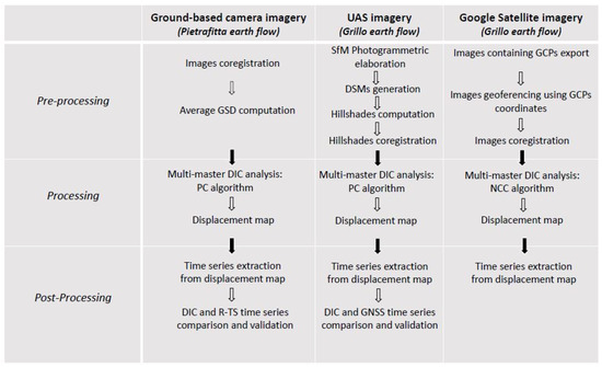
Figure 6.
General workflow for the instruments used.
The analyses performed with the dataset obtained from the ground-based camera (for the Pietrafitta earth flow) and those performed with the UAV dataset (for the Grillo earth flow) were then quantitatively compared with the data obtained with other monitoring tools (RTS and GNSS, respectively). For the Grillo earth flow, in addition to the mentioned methods of analysis, it was necessary to use a dataset of satellite images for long-term cognitive monitoring, which was previously performed for the Pietrafitta earth flow [15]. These DIC analyses using satellite images were used for a qualitative purpose, and the results were not quantitatively compared with the other techniques.
- (a)
- Analysis of the Pietrafitta earth flow
For the Pietrafitta earth flow, we commenced by co-registering the data acquired from the ground-based rugged camera. This co-registration process was undertaken as an initial step in the pre-processing stage. Subsequently, we computed the ground sampling distance (GSD), which represents the distance measured on the ground between two adjacent pixel centers (Pre-processing). The determination of the GSD holds pivotal importance as it serves as a key parameter to be considered before starting any monitoring activities. The GSD is calculated by taking into account the distance from the area of interest to the camera, along with the specific camera specifications, such as image and sensor widths, as well as the focal length. To clarify, it is worth noting that a larger GSD corresponds to a reduced spatial resolution within the captured image, resulting in a diminished visibility of finer details.
In this scenario, an average GSD value was determined, factoring in the distance arising from the camera’s non-perpendicular alignment relative to the line of sight (LoS), and this configuration can significantly distort the pixel size. Unfortunately, in this case, the value of the angle of incidence was omitted from the GSD calculation due to obvious measurement problems. To solve this problem and correct the GSD value, identifiable points of known sizes within the image were used as benchmarks.
To generate a displacement map, a multi-master analysis based on the DIC algorithm was carried out. The DIC is an optical numerical measurement technique that provides 2D surface deformation data by comparing co-registered digital images collected at different time points [42,43]. Displacement maps can be generated either by comparing a single pair of images taken before and after the deformation event (single analysis approach) or by utilizing an image stack of the same area (multi-master approach). The latter approach allows for the extrapolation of displacement time series for each selected pixel. The displacement analysis, performed to retrieve the movements that occurred at the Pietrafitta earth flow, relies on the phase correlation (PC) algorithm proposed in [44].
The PC algorithm is based on a frequency domain data representation computed through fast Fourier transforms (FTs) employing a moving window. It leverages the FT translation property, wherein a spatial domain shift between two images manifests as phase differences in the frequency domain [15]. In Equation (1), the functions F(u,v) and G(u,v) represent the respective FTs of f(x,y) and g(x,y), which we assume to be two image functions. The notation F − 1 signifies the inverse FT.
PC = F − 1 {F(u,v) ∗ G(u,v)|F(u,v) ∗ G(u,v)|} = F − 1{exp(−i(uΔx + vΔy))}
It is worth noting that three different displacement analyses, designated as A, B, and C, were performed for this case study using the PC algorithm. The primary objective was to evaluate variations in the accuracy of image analysis in response to different temporal resolutions. In this regard, different moving window sizes were used, and different approaches were tested, as detailed in Table 4.

Table 4.
Analysis performed for the Pietrafitta case study. Time span covered by analyses B and C refers to a single day (21 March 2018). Time is expressed as UTC +1. MM: multi-master analysis; SA: single analysis.
Considering the camera FOV, after the co-registration stage, a region of interest (RoI) was selected (Figure 1e), and the analysis was started (Processing). This was also to avoid the possible noise that could interfere with the analyses due to the presence of dense vegetation on the sides of the slope.
Harnessing the intrinsic capability of the DIC to quantitatively measure deformations that occurred between two or more sequentially acquired images captured at different times, we systematically extrapolated displacement time series for select deforming pixels in order to assess their evolution over time (post-processing). The verification and validation of these time series were conducted with regard to the available ancillary data, primarily derived from the RTS.
- (b)
- Analysis of the Grillo earth flow
With regard to the utilization of unmanned aerial systems (UASs) in the monitoring of the Grillo earth flow, we used the acquired aerial images to conduct photogrammetric processing through the well-known SfM technique [45]. The application of SfM photogrammetry to UAS imagery represents an emerging methodology that ensures high spatial resolution and flexible surveying periodicity, both of which are fundamental elements in earth flow monitoring [46,47,48]. Furthermore, UAS photogrammetry facilitates the mapping of remote and impervious areas [46,49,50].
Subsequently, 3D topographic models were generated and accurately georeferenced, enabling the derivation of DSMs and, consequently, the production of hillshades at a resolution of 20 cm\pixel for each UAS campaign (pre-processing).
Following this stage, a multi-master analysis employing the PC algorithm was used to generate a displacement map. This approach is similar to the methodology utilized for the Pietrafitta earth flow (processing). In this case, a window size of 32 pixels was employed for the analysis.
Similarly, we extrapolated the displacement time series for specific deforming pixels to evaluate their temporal evolution (post-processing). As described above, these time series were compared and validated with the available ancillary data (GNSS receiver, Table 1).
Moreover, Google® satellite imagery between 2009 and 2019 was exploited for image analysis. Firstly, we exclusively selected and exported images that contained well-known ground control points (GCPs). Subsequently, these images were georeferenced using the coordinates of the reference points themselves (pre-processing). Furthermore, the selected images were co-registered to facilitate the customary multi-master analysis utilizing the normalized cross-correlation (NCC) algorithm to generate the displacement map (processing). Unlike the previously introduced PC algorithm, it is worth noting that the NCC operates directly within the spatial domain of the data [51]. For each pixel of the master image, a square template window (STW) is defined, and various parameters, such as the number of pixels, mean, and standard deviation, are computed. Simultaneously, the search template, which shares the same size as the STW, is also moved within a defined search radius around each pixel of the secondary image, with similar parameters computed for this template. An iterative computation of the NCC value allows us to identify the optimal correspondence correlation surface. Mathematically, the NCC is defined as follows:
where f and t are the primary and secondary images, respectively; n is the number of pixels in each template; μ is the mean; and σ is the standard deviation.
In addition, in this case, the displacement time series from pixels were also extrapolated (post-processing).
4. Results
In this section, we present the main outcomes obtained in both temporal (e.g., displacement time series) and spatial terms (e.g., displacement maps). Furthermore, whenever feasible, we conducted comparisons among different datasets originating from the diverse monitoring instruments to validate the strength and direction of the linear relationship between the two quantitative variables, utilizing the Pearson correlation coefficient (r) [9].
4.1. Analysis of Images Acquired with a Ground-Based Camera (Pietrafitta Earth Flow)
Due to the presence of a pole-mounted camera, initially intended solely for visual inspection purposes, along with its optimal configuration in terms of distance and perspective, we were able to generate detailed displacement maps and time series. Specifically, this setup enabled us to detect the main direction of displacement of the geomorphological process, which aligns approximately with the line of the maximum slope gradient, and quantify its rate.
Figure 7 shows the displacement map resulting from the image analysis A (in Table 4) with a daily image capture frequency. It should be noted that the earth flow involves a considerable section of the slope with velocities that are notably higher in the inner part of the earth flow body and decreasing towards the edge and toe of the earth flow, closer to the road infrastructure. To validate displacement rates, we deployed a robotic total station on the right flank of the earth flow, looking at 11 reflectors placed along the slope. For this analysis, only reflector No. 3 was considered as it was located within the area covered by the visual beam (see Figure 1d for location). The comparison of data shows a high correlation in terms of direction (positive) and strength (strong), with a Pearson coefficient of r = 0.91 (chart in Figure 7). Importantly, the p-value is less than 0.05, confirming the statistical significance of the correlation between these two variables. Moreover, the chart in Figure 7 also compares the cumulative displacement of the monitoring point with rainfall data collected at the “Torrecuso” rain gauge. The acceleration trend due to the rainy events of 11–22 March 2018 (84.4 mm) is well evident.
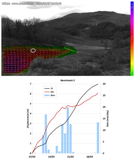
Figure 7.
Displacement map from image analysis (labeled A in Table 4) with a daily image frequency. The white circle represents the area of interest around reflector 3. The chart below shows the correlation among the displacement time series derived from the DIC analysis, total station reflector No. 3, and rainfall data.
We used hourly images to investigate the velocity rates achieved during periods characterized by high earth flow activity. As shown in Figure 8, on 21 March 2018, the earth flow exhibited a displacement of 18 cm in approximately 8.5 h, maintaining a constant velocity (R2 = 0.99) of about 2 cm/h (i.e., moderate velocity according to [52]). Again, the displacement measurements were confirmed by comparisons with reflector (No. 3) sightings made via RTS. Additionally, Figure 9, displaying the displacement map obtained through a single analysis approach (utilizing two images captured between 13:00 and 14:00), demonstrates the analysis’ remarkable sensitivity, capable of measuring approximately 5 cm of displacement within 1 h. This result aligns with RTS data, specifically referencing benchmark 3, which underscores that the maximum displacement velocity on 21 March 2018 was reached between 13:00 and 14:00.
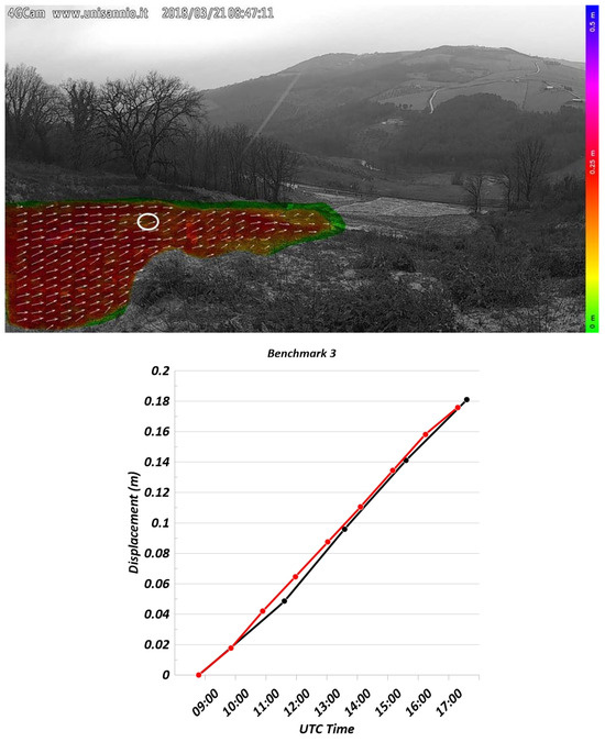
Figure 8.
Displacement map from the multi-master analysis (labeled B in Table 4) with an hourly image frequency. The white circle represents the area of interest around reflector 3. The chart below shows the correlation between the displacement time series derived from the DIC analysis (in red) and total station reflector No. 3 (in black).
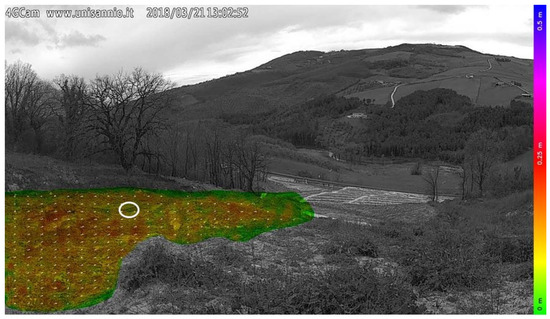
Figure 9.
Displacement map obtained using a single analysis approach (labeled C in Table 4). The white circle represents the area of interest around reflector 3.
4.2. Analysis of Images Acquired with an UAS Camera (Grillo Earth Flow)
For the Grillo earth flow, image analysis was carried out using accurate and georeferenced imagery generated through several UAS photogrammetric surveys. In contrast to the Pietrafitta earth flow, the displacements observed in this case are presented from a top-down perspective (zenithal view). Also, in this case study, the DIC techniques used enabled the identification of the main displacement direction of the earth flow process and the localization of its most active areas. The results show a heterogeneous displacement pattern characterized by localized reactivations occurring along two main directions (Figure 10). Additionally, these movements exhibited a “step-like” kinematic, potentially indicative of impulsive responses to rainfall events. This trend was confirmed via the available rainfall data collected from April 2022 to June 2023 at the “Orsara di Puglia” rain gauge, managed by the Protezione Civile (Centro Funzionale Decentrato, C.F.D.) of the Puglia Region, located about 2 km east and at the same elevation as the Grillo earth flow (Figure 11). Although the distance is not negligible, it is considered to be acceptable given the unique availability of the instrument and the gentle terrain catchments of the area [53]. In addition, for the type of analysis performed, even small cumulate changes would be irrelevant.
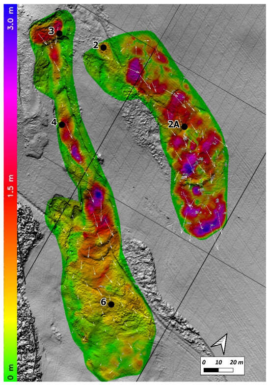
Figure 10.
Displacement map obtained from an UAS hillshade DIC analysis. The numbered black dots represent the position of the GNSS targets.
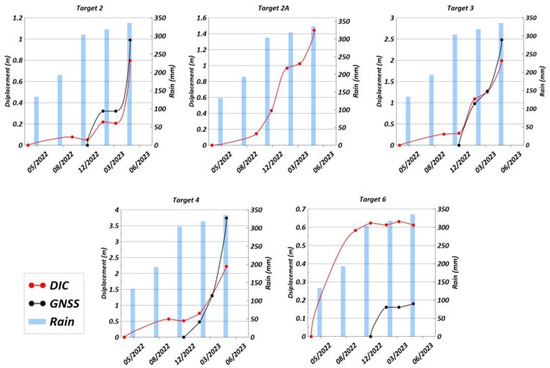
Figure 11.
Time series from the DIC and GNSS analyses using UAS imagery of the Grillo earth flow. Each shaded blue vertical bar represents the rainfall in three months from April 2022 to June 2023.
Furthermore, a reliability assessment of the measurements was carried out considering GNSS data for the targets placed on the ground (Figure 11). Since not all targets were placed and surveyed simultaneously with the UAS surveys, the reliability analysis was restricted to three specific targets (No. 2, No. 3, and No. 4). Although the sample size was limited (n = 4), the comparison shows a robust positive correlation in terms of direction (positive) and strength (strong) with a Pearson coefficient r = 0.99 for each of the targets. Given that the p-value is less than 0.05, we can conclude that the correlation between these two variables holds statistical significance. The GNSS analysis for target No. 2a is not present because, having been installed on 23 March, it was no longer found on 23 May, probably due to surface modifications caused by the landslide process under consideration (no data available). Regarding target No. 6, it is probable that the reference area experienced its maximum displacement before the installation of the target itself. In fact, the latest GNSS measurements validate the trend recorded through the DIC, with comparable absolute displacements.
Overall, the accuracy of the DIC analysis ranged from 0.2 to more than 1 m, namely from 1 pixel to more than 5 pixels.
4.3. Analysis of Images Acquired with a Satellite Camera (Grillo Earth Flow)
A further analysis was conducted using optical Google® satellite imagery for the Grillo earth flow. As previously mentioned with regard to UAS imagery, the displacements detected are presented in an overhead perspective (zenithal view). The employed DIC techniques provided sufficient detail to discern the main direction of movement in the geomorphological process and identify the most active areas (Figure 12). The results confirmed the heterogeneous displacement pattern observed earlier using UAS imagery, with localized unstable areas along two primary directions. The displacement observed at the source area (area of interest) can be attributed to a retrogressive kinematic process (Figure 12). This can be witnessed by the presence of grabens, scarps, and back-tilted surfaces mainly linked to normal fault-like structures in the source area. These extensive kinematic elements cause an upstream widening of the earth flow, resulting in a movement inverse to the “natural direction” (i.e., downstream) in the DIC analysis.
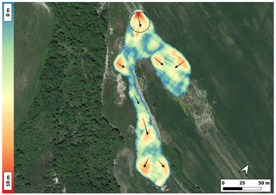
Figure 12.
Displacement map from an image analysis using satellite imagery of the Grillo earth flow. The black circle represents the area of interest. The arrows represent the main displacement directions.
5. Discussion
The results presented above appear promising for all configurations adopted (e.g., the various platforms), but their potential and limitations still warrant further investigation. Nevertheless, the utilization of DIC techniques is steadily gaining popularity as a method for data acquisition and processing. The necessary setup is often cost-effective and straightforward to install, enabling the acquisition of substantial amounts of data across diverse environments with minimal effort.
With regard to the Pietrafitta earth flow, due to the optimal configuration in terms of distance and perspective of the pole-mounted camera, we were able to generate detailed displacement maps and time series. This allowed us to discern the main displacement direction of the geomorphological process—approximately aligned with the maximum slope gradient—and to quantify its rate. Furthermore, when comparing the displacement rates with the data obtained from reflectors sighted by an independent RTS, we observed a close correlation in terms of both direction (positive) and strength (strong). However, it is important to note that this comparison was made on the horizontal component measured by the RTS, which is the component most perpendicular to the image plane. This choice was made to ensure maximum comparability. This aspect is of particular significance in imaging since post-processing still requires complex steps, including georeferencing, georectification, and feature tracking. These steps are necessary to transform oblique images into meaningful data for quantitative analysis (e.g., velocity rates). In this regard, several attempts have been made, and today, there are some free and open-source applications available to overcome these obstacles [54,55]. Furthermore, looking ahead to future monitoring campaigns, particular attention must be paid to achieving the optimal geometric configuration for measuring the intended movement while also keeping factors such as the angle of incidence and position of the camera in relation to the monitoring target under control. However, this is not always possible and there are cases where the distance between the object and the sensor, as well as its GSD, may increase or may not be in the optimal configuration. In these cases, it may be advantageous to use higher-resolution cameras, such as gigapixel or depth cameras [56].
In reference to the Grillo earth flow, which was analyzed using images acquired by a UAS, a critical aspect lies in the precise determination of the image capture point due to the utilization of an aerial platform. This specific configuration granted us a comprehensive, bird’s-eye view of the entire earth flow kinematics. In the author’s perspective, when dealing with landslides of this type, specifically earth flows, this vantage point represents the optimal approach for generating a comprehensive map of the unstable sectors and their respective displacements. Regarding the timing of these acquisitions, there are two factors to consider: (a)the extreme versatility of the acquisition technique (survey through a drone) permits us to adjust—increasing or decreasing—the frequency of data collection in accordance with the evolving state of the geomorphological process; (b)the necessity for a well-trained team and physical accessibility to the investigation site can influence the planning and execution of these acquisitions. The incorporation of ground-based targets for georeferencing significantly facilitated data processing and analysis while enhancing their overall reliability. However, even in the absence of georeferenced data, UAS surveys, when coupled with DIC processing, still enable us to initiate the mapping and monitoring of earth flows, even when other sources of information and control monitoring are unavailable.
The analysis of satellite imagery of the Grillo earth flow provided us with a general understanding of the evolution of the geomorphological process over the past decade, thereby facilitating knowledge monitoring. Although the absence of ancillary data from conventional monitoring techniques did not allow a quantitative assessment of the displacement values, our analysis confirmed the potentiality to derive surface displacement data from Google® Earth images [57], especially for a knowledge monitoring of an earth flow. This application could be utilized to obtain very high geometric resolution (i.e., GSD) satellite imagery easily [58]; however, when conducting DIC analyses for processes characterized by high seasonality, especially those occurring within relatively vegetated areas, it is advisable to avoid using optical images, be they satellite based or otherwise. This is because changes in vegetation can introduce a multitude of processing errors. In such cases, it is recommended to employ hillshade products instead.
Moreover, the results and interpretation of monitoring activities carried out at the two study sites allowed us to observe the typical earth flow activity: slow localized movements (e.g., Grillo earth flow) and surging events (e.g., Pietrafitta earth flow) [52].
The key role of the hydrologic forcing on earth flow movement velocity was demonstrated at the Pietrafitta study site: the intensive rainfall period of January–March 2018 and the snow melting that occurred at the end of February 2018, increasing the pore-water pressure causing a fluidization of the earth flow material and resulting in a surge event. In this phase, the highest localized movement velocity reached was about 0.63 m/day. This value is consistent with other earth flow surge speeds in the literature [38,59]. Meanwhile, the distribution of the displacement and average velocity observed along the longitudinal axis of the right branch of the Grillo earth flow proved the importance of the basal slip-surface geometry [60] on earth flow activity, expressed as the relationship between morphological structures and velocity distributions. Indeed, as observed in Figure 10, the highest displacement rates were measured where the flow movement was bounded by normal and strike–slip faults, whereas the lowest velocities were measured where thrust faults were present (Figure 1e). As reported in [60], extensional and compression structures could be associated with risers and treads, respectively, in the basal slip surface.
To contextualize the contribution of our study and, therefore, of DIC techniques within geotechnical monitoring, with a specific focus on monitoring earth flows facing linear infrastructures, Figure 13 shows the application domains of the monitoring techniques used in this study and presented using the classification proposed in [34]. Considering the three main monitoring categories proposed, namely knowledge, control, and emergency monitoring, and drawing insights from our practical field experiences (indicated by colored dots in Figure 13), the utilization of the DIC has been generalized (represented by colored areas in Figure 13) based on the specific platform used and its general purpose.
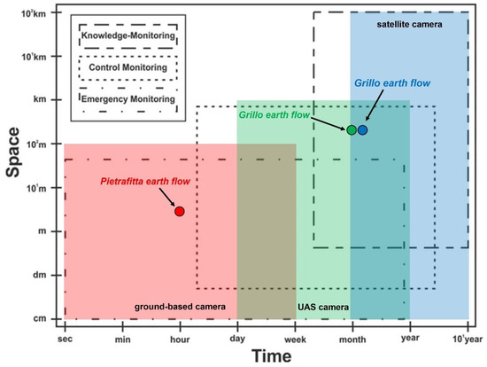
Figure 13.
Usage domains of the presented monitoring techniques on a space–time chart based on the used platforms (red: ground-based camera; green: UAS camera; blue: satellite camera). The boxes indicate the different types of geotechnical monitoring: knowledge, control, and emergency monitoring (modified from [34]).
For example, ground-based cameras, such as the one used in the Pietrafitta earth flow, demonstrated great potential in emergency and, partially, control monitoring. Cameras mounted on drones (UASs), as in the case of the Grillo earth flow, give a great advantage, especially for control monitoring. Satellite images, such as those employed for the Grillo earth flow, seem to be crucial for knowledge monitoring.
6. Conclusions
The present study has examined the use of digital image correlation (DIC) for the displacement monitoring of earth flows by presenting the outcomes from the evaluation and comparison of distinctive techniques for three different study sites in the Pietrafitta and Grillo earth flows. Based on the results presented in this study and considering the main potentialities of the DIC techniques that have emerged from this research, the following general considerations can be made:
- The spatially continuous coverage, given by the DIC technique, affords the opportunity to perform monitoring with clear, practical advantages. Indeed, this approach enables us to (i) comprehensively cover large areas, thereby avoiding the risk of underestimating geomorphological processes; (ii) increase the statistical robustness of the acquired data; and (iii) identify the most active sectors and their rates of movement. These aspects are particularly relevant when monitoring complex kinematic phenomena like earth flows;
- The versatility of DIC, in terms of the facility of the installation of sensors, cost-effectiveness, and compatibility with various platforms, makes this technique a competitive, adaptable, and ready-to-use solution. This versatility holds significant importance in the field of geotechnical asset management (GAM);
- The proven reliability in terms of both accuracy (e.g., high correlation with RTS; r = 0.91) and sensitivity (ability to measure approximately 5 cm of displacement within 1 h) lays the foundation for extensive use of the DIC techniques presented so far. Furthermore, through future developments, e.g., involving the automation of analyses, the DIC could easily be implemented as a technique underlying early warning systems (EWS).
In the view and opinion of the authors, the most appropriate way to quantitatively monitor earth flows in the case of control monitoring is to use the DIC from UAS data and through hillshades for several reasons: (i) they are not subject to variations in vegetation; (ii) due to the high resolution, it is possible to also identify localized displacements without running the risk of ambiguity; and (iii) low cost of realization. For continuous and emergency monitoring, the most effective way to quantitatively monitor the earth flow is to use low-cost ground-based cameras that maintain a good cost–benefit ratio.
Although it has been shown that the techniques used, with their different configurations and acquisition platforms, can be immediately exploited for the above-mentioned purposes, their actual benefit will only materialize once some of the main limitations, which also emerged in our work, have been addressed. For example, with regard to ground-based cameras, great care should be paid to achieving the optimal geometric configuration for measuring the intended movement while also maintaining the angle of incidence and position of the camera in relation to the targets.
Finally, from our perspective, the revised rating presented in Figure 13 and a focus on imaging (DIC) could be very useful for the risk management of earth flows in the presence of linear infrastructures.
Author Contributions
Conceptualization, D.M. and S.R.; methodology, D.M. and S.R.; formal analysis, D.M.; investigation, D.M.; resources, A.C. and P.M.; writing—original draft preparation, D.M. and S.R.; writing—review and editing, D.M., S.R., A.C., P.M. and P.R.; supervision, F.M.G. and P.R. All authors have read and agreed to the published version of the manuscript.
Funding
This research was funded by the Department of Sciences and Technologies (DST)—University of Sannio (Resp. Paola Revellino) and by the Campania Region—Civili Protection Sector (UOR:SI0050—Resp. Francesco M. Guadagno).
Data Availability Statement
The datasets generated and/or analyzed during the current study are available from the corresponding author upon reasonable request.
Acknowledgments
The authors wish to thank Luigi Guerriero for the ground-based camera and robotic total station installation and Daniele Cifaldi for helping with the GNSS data collection.
Conflicts of Interest
The authors declare no conflict of interest.
References
- Revellino, P.; Grelle, G.; Donnarumma, A.; Guadagno, F.M. Structurally Controlled Earth Flows of the Benevento Province (Southern Italy). Bull. Eng. Geol. Environ. 2010, 69, 487–500. [Google Scholar] [CrossRef]
- Bertello, L.; Berti, M.; Castellaro, S.; Squarzoni, G. Dynamics of an Active Earthflow Inferred from Surface Wave Monitoring. J. Geophys. Res. Earth Surf. 2018, 123, 1811–1834. [Google Scholar] [CrossRef]
- Malet, J.-P.; Laigle, D.; Remaître, A.; Maquaire, O. Triggering Conditions and Mobility of Debris Flows Associated to Complex Earthflows. Geomorphology 2005, 66, 215–235. [Google Scholar] [CrossRef]
- Baum, R.L.; Savage, W.Z.; Wasowski, J. Mechanics of Earth Flows. In Proceedings of the International Workshop on Occurrence and Mechanisms of Flows in Natural Slopes and Earthfills, Sorrento, Italy, 14–16 May 2003; 2003; p. 8. [Google Scholar]
- Di Crescenzo, G.; Santo, A. Debris Slides–Rapid Earth Flows in the Carbonate Massifs of the Campania Region (Southern Italy): Morphological and Morphometric Data for Evaluating Triggering Susceptibility. Geomorphology 2005, 66, 255–276. [Google Scholar] [CrossRef]
- Bovis, M.J.; Jones, P. Holocene History of Earthflow Mass Movements in South-Central British Columbia: The Influence of Hydroclimatic Changes. Can. J. Earth Sci. 1992, 29, 1746–1755. [Google Scholar] [CrossRef]
- Mulas, M.; Ciccarese, G.; Truffelli, G.; Corsini, A. Integration of Digital Image Correlation of Sentinel-2 Data and Continuous GNSS for Long-Term Slope Movements Monitoring in Moderately Rapid Landslides. Remote Sens. 2020, 12, 2605. [Google Scholar] [CrossRef]
- Quinn, P.E.; Hutchinson, D.J.; Diederichs, M.S.; Rowe, R.K. Regional-Scale Landslide Susceptibility Mapping Using the Weights of Evidence Method: An Example Applied to Linear Infrastructure. Can. Geotech. J. 2010, 47, 905–927. [Google Scholar] [CrossRef]
- Picarelli, L.; Russo, C. Remarks on the Mechanics of Slow Active Landslides and the Interaction with Man-Made Works. In Landslides: Evaluation and Stabilization; A. A. Balkema: Leiden, The Netherlands, 2004; pp. 1141–1176. [Google Scholar]
- Di Maio, C.; Vassallo, R.; Scaringi, G.; Scaringi, G.; Pontolillo, D.M.; Grimaldi, G.M. Monitoring and analysis of an earthflow in tectonized clay shales and study of a remedial intervention by KCl wells. Riv. Ital. Geotec. 2017, 51, 48–63. [Google Scholar] [CrossRef]
- Hungr, O.; Fell, R.; Couture, R.; Eberhardt, E. Landslide Risk Management; CRC Press: Boca Raton, FL, USA, 2005; ISBN 978-1-4398-3371-1. [Google Scholar]
- Scaioni, M. (Ed.) Modern Technologies for Landslide Monitoring and Prediction; Springer: Berlin/Heidelberg, Germany, 2015; ISBN 978-3-662-45930-0. [Google Scholar]
- Giordan, D.; Allasia, P.; Manconi, A.; Baldo, M.; Santangelo, M.; Cardinali, M.; Corazza, A.; Albanese, V.; Lollino, G.; Guzzetti, F. Morphological and Kinematic Evolution of a Large Earthflow: The Montaguto Landslide, Southern Italy. Geomorphology 2013, 187, 61–79. [Google Scholar] [CrossRef]
- Bardi, F.; Raspini, F.; Frodella, W.; Lombardi, L.; Nocentini, M.; Gigli, G.; Morelli, S.; Corsini, A.; Casagli, N. Monitoring the Rapid-Moving Reactivation of Earth Flows by Means of GB-InSAR: The April 2013 Capriglio Landslide (Northern Appennines, Italy). Remote Sens. 2017, 9, 165. [Google Scholar] [CrossRef]
- Mazza, D.; Cosentino, A.; Romeo, S.; Mazzanti, P.; Guadagno, F.M.; Revellino, P. Remote Sensing Monitoring of the Pietrafitta Earth Flows in Southern Italy: An Integrated Approach Based on Multi-Sensor Data. Remote Sens. 2023, 15, 1138. [Google Scholar] [CrossRef]
- Malet, J.-P.; Maquaire, O.; Calais, E. The Use of Global Positioning System Techniques for the Continuous Monitoring of Landslides: Application to the Super-Sauze Earthflow (Alpes-de-Haute-Provence, France). Geomorphology 2002, 43, 33–54. [Google Scholar] [CrossRef]
- Castagnetti, C.; Bertacchini, E.; Corsini, A.; Capra, A. Multi-Sensors Integrated System for Landslide Monitoring: Critical Issues in System Setup and Data Management. Eur. J. Remote Sens. 2013, 46, 104–124. [Google Scholar] [CrossRef]
- Hermle, D.; Gaeta, M.; Krautblatter, M.; Mazzanti, P.; Keuschnig, M. Performance Testing of Optical Flow Time Series Analyses Based on a Fast, High-Alpine Landslide. Remote Sens. 2022, 14, 455. [Google Scholar] [CrossRef]
- Bickel, V.T.; Manconi, A.; Amann, F. Quantitative Assessment of Digital Image Correlation Methods to Detect and Monitor Surface Displacements of Large Slope Instabilities. Remote Sens. 2018, 10, 865. [Google Scholar] [CrossRef]
- Mazzanti, P.; Caporossi, P.; Muzi, R. Sliding Time Master Digital Image Correlation Analyses of CubeSat Images for Landslide Monitoring: The Rattlesnake Hills Landslide (USA). Remote Sens. 2020, 12, 592. [Google Scholar] [CrossRef]
- Hermle, D.; Keuschnig, M.; Krautblatter, M. Potential of Multisensor Assessment Using Digital Image Correlation for Landslide Detection and Monitoring; Copernicus Meetings. 2020. [Google Scholar]
- Lacroix, P.; Araujo, G.; Hollingsworth, J.; Taipe, E. Self-Entrainment Motion of a Slow-Moving Landslide Inferred from Landsat-8 Time Series. J. Geophys. Res. Earth Surf. 2019, 124, 1201–1216. [Google Scholar] [CrossRef]
- Daehne, A.; Corsini, A. Kinematics of Active Earthflows Revealed by Digital Image Correlation and DEM Subtraction Techniques Applied to Multi-Temporal LiDAR Data: Kinematics of Active Earthflows. Earth Surf. Processes Landf. 2013, 38, 640–654. [Google Scholar] [CrossRef]
- Travelletti, J.; Oppikofer, T.; Delacourt, C. Monitoring Landslide Displacements during a Controlled Rain Experiment Using a Long-Range Terrestrial Laser Scanning (TLS); Chen, J., Jiang, J., Eds.; Hans-Gerd MAAS: Beijing, China, 2008; Volume XXXVII, p. 6. [Google Scholar]
- Tondo, M.; Mulas, M.; Ciccarese, G.; Marcato, G.; Bossi, G.; Tonidandel, D.; Mair, V.; Corsini, A. Detecting Recent Dynamics in Large-Scale Landslides via the Digital Image Correlation of Airborne Optic and LiDAR Datasets: Test Sites in South Tyrol (Italy). Remote Sens. 2023, 15, 2971. [Google Scholar] [CrossRef]
- Travelletti, J.; Delacourt, C.; Allemand, P.; Malet, J.-P.; Schmittbuhl, J.; Toussaint, R.; Bastard, M. Correlation of Multi-Temporal Ground-Based Optical Images for Landslide Monitoring: Application, Potential and Limitations. ISPRS J. Photogramm. Remote Sens. 2012, 70, 39–55. [Google Scholar] [CrossRef]
- Travelletti, J.; Malet, J.-P.; Delacourt, C. Image-Based Correlation of Laser Scanning Point Cloud Time Series for Landslide Monitoring. Int. J. Appl. Earth Obs. Geoinf. 2014, 32, 1–18. [Google Scholar] [CrossRef]
- Stumpf, A.; Malet, J.-P.; Delacourt, C. Correlation of Satellite Image Time-Series for the Detection and Monitoring of Slow-Moving Landslides. Remote Sens. Environ. 2017, 189, 40–55. [Google Scholar] [CrossRef]
- Motta, M.; Gabrieli, F.; Corsini, A.; Manzi, V.; Ronchetti, F.; Cola, S. Landslide Displacement Monitoring from Multi-Temporal Terrestrial Digital Images: Case of the Valoria Landslide Site. In Landslide Science and Practice: Volume 2: Early Warning, Instrumentation and Monitoring; Margottini, C., Canuti, P., Sassa, K., Eds.; Springer: Berlin/Heidelberg, Germany, 2013; pp. 73–78. ISBN 978-3-642-31445-2. [Google Scholar]
- Travelletti, J.; Delacourt, C.; Malet, J.-P.; Allemand, P.; Schmittbuhl, J.; Toussaint, R. Performance of Image Correlation Techniques for Landslide Displacement Monitoring. In Landslide Science and Practice: Volume 2: Early Warning, Instrumentation and Monitoring; Margottini, C., Canuti, P., Sassa, K., Eds.; Springer: Berlin/Heidelberg, Germany, 2013; pp. 217–226. ISBN 978-3-642-31445-2. [Google Scholar]
- Dematteis, N.; Giordan, D. Comparison of Digital Image Correlation Methods and the Impact of Noise in Geoscience Applications. Remote Sens. 2021, 13, 327. [Google Scholar] [CrossRef]
- Corominas, J.; Van Westen, C.; Frattini, P.; Cascini, L.; Malet, J.-P.; Fotopoulou, S.; Catani, F.; Van Den Eeckhaut, M.; Mavrouli, O.; Agliardi, F.; et al. Recommendations for the Quantitative Analysis of Landslide Risk. Bull. Eng. Geol. Environ. 2013, 73, 209–263. [Google Scholar] [CrossRef]
- Chowdhury, R.; Flentje, P. Role of Slope Reliability Analysis in Landslide Risk Management. Bull. Eng. Geol. Environ. 2003, 62, 41–46. [Google Scholar] [CrossRef]
- Mazzanti, P. Toward Transportation Asset Management: What Is the Role of Geotechnical Monitoring? J. Civ. Struct. Health Monit. 2017, 7, 645–656. [Google Scholar] [CrossRef]
- Whiteley, J.S.; Watlet, A.; Kendall, J.M.; Chambers, J.E. Brief Communication: The Role of Geophysical Imaging in Local Landslide Early Warning Systems. Nat. Hazards Earth Syst. Sci. 2021, 21, 3863–3871. [Google Scholar] [CrossRef]
- Hungr, O.; Leroueil, S.; Picarelli, L. The Varnes Classification of Landslide Types, an Update. Landslides 2014, 11, 167–194. [Google Scholar] [CrossRef]
- Pinto, F.; Guerriero, L.; Revellino, P.; Grelle, G.; Senatore, M.R.; Guadagno, F.M. Structural and Lithostratigraphic Controls of Earth-Flow Evolution, Montaguto Earth Flow, Southern Italy. J. Geol. Soc. 2016, 173, 649–665. [Google Scholar] [CrossRef]
- Guerriero, L.; Revellino, P.; Grelle, G.; Fiorillo, F.; Guadagno, F. Landslides and Infrastructures: The Case of the Montaguto Earth Flow in Southern Italy. Ital. J. Eng. Geol. Environ. 2013, 2013, 459–466. [Google Scholar] [CrossRef]
- Ferrigno, F.; Gigli, G.; Fanti, R.; Intrieri, E.; Casagli, N. GB-InSAR Monitoring and Observational Method for Landslide Emergency Management: The Montaguto Earthflow (AV, Italy). Nat. Hazards Earth Syst. Sci. 2017, 17, 845–860. [Google Scholar] [CrossRef]
- Casagli, N.; Intrieri, E.; Tofani, V.; Gigli, G.; Raspini, F. Landslide Detection, Monitoring and Prediction with Remote-Sensing Techniques. Nat. Rev. Earth Environ. 2023, 4, 51–64. [Google Scholar] [CrossRef]
- Pearson’s Correlation Coefficient. In Encyclopedia of Public Health; Kirch, W. (Ed.) Springer: Dordrecht, The Netherlands, 2008; pp. 1090–1091. ISBN 978-1-4020-5613-0. [Google Scholar]
- Caporossi, P.; Mazzanti, P.; Bozzano, F. Digital Image Correlation (DIC) Analysis of the 3 December 2013 Montescaglioso Landslide (Basilicata, Southern Italy): Results from a Multi-Dataset Investigation. ISPRS Int. J. Geo-Inf. 2018, 7, 372. [Google Scholar] [CrossRef]
- Pan, B.; Xie, H.; Wang, Z.; Qian, K.; Wang, Z. Study on Subset Size Selection in Digital Image Correlation for Speckle Patterns. Opt. Express 2008, 16, 7037. [Google Scholar] [CrossRef]
- Tong, X.; Ye, Z.; Xu, Y.; Gao, S.; Xie, H.; Du, Q.; Liu, S.; Xu, X.; Liu, S.; Luan, K.; et al. Image Registration with Fourier-Based Image Correlation: A Comprehensive Review of Developments and Applications. IEEE J. Sel. Top. Appl. Earth Obs. Remote Sens. 2019, 12, 4062–4081. [Google Scholar] [CrossRef]
- Carrivick, J.; Smith, M.; Quincey, D. Structure from Motion in the Geosciences; Wiley, Blackwell: Chichester, UK; Ames, IA, USA, 2016; ISBN 978-1-118-89584-9. [Google Scholar]
- Mugnai, F.; Masiero, A.; Angelini, R.; Cortesi, I. High-Resolution Monitoring of Landslides with UAS Photogrammetry and Digital Image Correlation. Eur. J. Remote Sens. 2023, 56, 2216361. [Google Scholar] [CrossRef]
- Angeli, M.-G.; Pasuto, A.; Silvano, S. A Critical Review of Landslide Monitoring Experiences. Eng. Geol. 2000, 55, 133–147. [Google Scholar] [CrossRef]
- Mucchi, L.; Jayousi, S.; Martinelli, A.; Caputo, S.; Intrieri, E.; Gigli, G.; Gracchi, T.; Mugnai, F.; Favalli, M.; Fornaciai, A.; et al. A Flexible Wireless Sensor Network Based on Ultra-Wide Band Technology for Ground Instability Monitoring. Sensors 2018, 18, 2948. [Google Scholar] [CrossRef]
- Lindner, G.; Schraml, K.; Mansberger, R.; Hübl, J. UAV Monitoring and Documentation of a Large Landslide. Appl. Geomat. 2016, 8, 1–11. [Google Scholar] [CrossRef]
- Sestras, P.; Bilașco, Ș.; Roșca, S.; Dudic, B.; Hysa, A.; Spalević, V. Geodetic and UAV Monitoring in the Sustainable Management of Shallow Landslides and Erosion of a Susceptible Urban Environment. Remote Sens. 2021, 13, 385. [Google Scholar] [CrossRef]
- Lewis, J.P. Fast Template Matching. In Proceedings of the Vision Interface 95, Canadian Image Processing and Pattern Recognition Society, Quebec City, QC, Canada, 15–19 May 1995; pp. 120–123. [Google Scholar]
- Cruden, D.M.; Varnes, D.J. Landslide Types and Processes; Special Report National Research Council Transportation Research; Board Transportation Research Board, National Academy of Sciences: Washington, DC, USA, 1996; Volume 247, pp. 36–75. [Google Scholar]
- Gariano, S.L.; Sarkar, R.; Dikshit, A.; Dorji, K.; Brunetti, M.T.; Peruccacci, S.; Melillo, M. Automatic Calculation of Rainfall Thresholds for Landslide Occurrence in Chukha Dzongkhag, Bhutan. Bull. Eng. Geol. Environ. 2019, 78, 4325–4332. [Google Scholar] [CrossRef]
- Messerli, A.; Grinsted, A. Image Georectification and Feature Tracking Toolbox: ImGRAFT. Geosci. Instrum. Methods Data Syst. 2015, 4, 23–34. [Google Scholar] [CrossRef]
- How, P.; Hulton, N.R.J.; Buie, L.; Benn, D.I. PyTrx: A Python-Based Monoscopic Terrestrial Photogrammetry Toolset for Glaciology. Front. Earth Sci. 2020, 8, 21. [Google Scholar] [CrossRef]
- Romeo, S.; Cosentino, A.; Giani, F.; Mastrantoni, G.; Mazzanti, P. Combining Ground Based Remote Sensing Tools for Rockfalls Assessment and Monitoring: The Poggio Baldi Landslide Natural Laboratory. Sensors 2021, 21, 2632. [Google Scholar] [CrossRef]
- Guerriero, L.; Di Martire, D.; Calcaterra, D.; Francioni, M. Digital Image Correlation of Google Earth Images for Earth’s Surface Displacement Estimation. Remote Sens. 2020, 12, 3518. [Google Scholar] [CrossRef]
- Stumpf, A.; Malet, J.-P.; Allemand, P.; Ulrich, P. Surface Reconstruction and Landslide Displacement Measurements with Pléiades Satellite Images. ISPRS J. Photogramm. Remote Sens. 2014, 95, 1–12. [Google Scholar] [CrossRef]
- Keefer, D.K.; Johnson, A.M. Earth Flows: Morphology, Mobilization, and Movement; Professional Paper; U.S. Geological Survey: Washington, DC, USA, 1983; Volume 1264.
- Guerriero, L.; Coe, J.A.; Revellino, P.; Grelle, G.; Pinto, F.; Guadagno, F.M. Influence of Slip-Surface Geometry on Earth-Flow Deformation, Montaguto Earth Flow, Southern Italy. Geomorphology 2014, 219, 285–305. [Google Scholar] [CrossRef]
Disclaimer/Publisher’s Note: The statements, opinions and data contained in all publications are solely those of the individual author(s) and contributor(s) and not of MDPI and/or the editor(s). MDPI and/or the editor(s) disclaim responsibility for any injury to people or property resulting from any ideas, methods, instructions or products referred to in the content. |
© 2023 by the authors. Licensee MDPI, Basel, Switzerland. This article is an open access article distributed under the terms and conditions of the Creative Commons Attribution (CC BY) license (https://creativecommons.org/licenses/by/4.0/).