Abstract
The present work reports on the first evidence of a possible hypervelocity impact crater in the Sultanate of Oman. The impact origin of the structure is determined based on field observations, microscopic observations of shatter cones, planar fractures (PFs) and feather features (FFs) in quartz, calcite, and feldspar, and melt-bearing polymict breccias with various types of melts. The structure consists of an elliptical bowl-shaped ridge 750 m long and 550 m wide, oriented roughly north-northeast to south-southwest. The elliptical shape and relief asymmetry indicate an oblique collision. The precursor target lithologies include local late Proterozoic Masirah Bay siliciclastic formations, carbonate and acidic volcanic rocks of the late Precambrian Halfayn Formation, and basement rocks. The crater rim, up to 15–20 m above ground, is composed of quartzite, jasper, agate, monomict siliceous and hematite breccia, and metamorphosed shale (hornfels). An ejecta blanket composed of target rocks covers the floor, outer rim, and the area extending to the immediate northeast and east of the structure. Quaternary aeolian sand covers most of the crater surface, including the 1 to 2 m thick melt-rich polymict breccia found in the crater center. The planar fractures (PFs) and feather features (FFS) in quartz and feldspar suggest a low shock pressure between 5 and 14 GPa. Our observations are consistent with set criterions for impact crater identification, confirming the possible impact origin of the Mahout structure.
1. Introduction
Throughout its geological history, Earth has withstood asteroid and comet bombardment events e.g., [1,2,3]. One hundred and ninety impact craters have been identified so far on Earth [4,5]. However, some structures have not been confirmed to be of impact origin due to the lack of substantial evidence for an impact origin. These craters undergo erosion, deformation, alteration, and subsidence after impact. In total, only 21 (11.5%) impact craters are less than 1 km in diameter and very young (0.1–1 Ma). Dence [6,7] distinguished four types of craters in terms of impact origin:
- Impact pits formed by intact meteorites.
- Impact craters formed by broken up and deformed meteorites, but the target materials are not subjected to shock metamorphism.
- Simple hypervelocity craters, consisting of uplifted and overturned rim rocks and a breccia lens.
- Complex hypervelocity craters that are relatively shallow in terms of depth–diameter ratio, with a central uplifted area and slumped or depressed rim structure.
Various geological processes, such as magmatic processes, volcanism, glacial activity, and biogenic processes, can create circular features that may resemble impact structures. For this reason, it is essential to consider specific diagnostic criteria associated with shock metamorphism and meteorite impacts. Definitive evidence for impact craters usually relies on records of mineralogical alterations uniquely caused by shock waves. Such evidence includes the following: shatter cones, planar fractures (PFs), feather features (FFs), planar deformation features (PDFs), high-pressure minerals (e.g., stishovite), high-temperature glasses and melts, and chemical signatures of the projectile within the impacted rocks e.g., [3,8,9,10,11,12,13] However, the identification of small impact craters or crater pits (<200 m in diameter) in unconsolidated target rocks is not easy, because the most unequivocal criteria are the presence of shock metamorphic criteria in target rocks, which will spread out over a large area and, thus, shock metamorphic features may not be found [14,15,16].
Planar fractures (PFs) are parallel sets of several planar cracks in mineral grains. The fractures are typically 5–10 µm wide and spaced 15–20 µm apart in individual grains [17,18]. Planar deformation features (PDFs) in quartz are defined by specific Miller indices, in particular in the (10–11), (1012) and (1013) planes, where they form multiple planar sets of 1–2 μm thick lamellae [17,18,19,20,21,22,23]. Gilkson et al. [24] proposed a shock metamorphic model and recommended several criteria to identify PDFs in quartz, which include the following: PDFs are often multiple, do not cross grain boundaries, and have a strict planar character; typically, they are 2–4 microns wide and closely spaced, typically at 10–20 microns; and they possess unique crystallographic orientations. Accordingly, universal stage measurements of PDFs in quartz are essential to differentiate between shock PDFs from endogenic tectonic–metamorphic origin [24]. Feather textures consist of a planar fracture, from which a group of thinly spaced lamellae branch off, typically only from one side. They occur as short, parallel to subparallel lamellae, found in combination with a planar fracture (PF) from which they emanate [25].
Oman’s central desert contains several ring structures associated with deep-seated faults and collapsed salt domes. No surface impact crater in Oman has yet been discovered. However, Levell et al. [26] reported the possibility of an Albian sub-surface complex impact crater in the Murshid area in southern Oman. Olds [27] suggested that the Semail ophiolite of Oman (94 Ma) was formed and obducted on the Oman plate margin through impact during the K-Pg boundary. The impact basin shows a circular rim segment with a ∼250 km radius of curvature, implying an original ∼500 km diameter impact basin before subsequent deformation/destruction at plate boundaries. Impact craters close to Oman include the Saqqar impact crater [28], the Wabar impact crater in Saudi Arabia [29], the Kamil crater in Egypt [30], and the Waqf As Suwwan impact crater in Jordan [31].
The Mahout structure is one of the structures speculated by local geologists to be related to deep-seated faults and salt domes e.g., [32,33]. However, no previous studies have been conducted or have reported on this structure to confirm its origin.
This study aims to assess the Mahout structure and provide evidence for its possible impact origin through mineralogical, petrological, and geological studies, aiding in identifying potential impact diagnostic criteria for structures of interest, such as structural and mineralogical evidence, deformation features, and melt products. The preliminary results of a geophysical campaign complement the identification of impact criteria.
2. Geological Setting
The Mahout structure is located in the stony desert of the Huqf region in central Oman (20°46′33.64″ N, 58°1′26.81″ E), approximately 30 km southeast of the city of Mahout (Figure 1). The crater is found within simple geological settings: a flat, rocky desert surface and horizontally layered siliciclastic rocks overlaying thin layers of late Proterozoic carbonate interlayered with acidic volcanics and basement rocks (Figure 2). The Huqf area is a low-relief (<70 m) piedmont, located at the foot of the north–south extremity of a north–south fault, hills, and mesas 100 m above sea level. The area is characterized by the absence of wadi channels that cause bedrock erosion, leaving surface rocks intact for millions of years. The main stratigraphic units emerging in the Mahout crater region form the basis of the Huq Supergroup, which spans ages from 630 to 550 Ma (Allen and Leather, 2006, [34]). This unit consists of Precambrian siliciclastic rocks of the Masirah Bay Formation, composed mostly of quartz arenite sandstone, siltstone, and shale, with little intervening limestone and dolomite (Allen and Leather, 2006 [34]). Overall, only the upper part of the Masirah Bay Formation is exposed in the crater region with a thickness of 30–45 m [35,36]. The intercalated carbonate and siltstone layers occur just above the thinly layered sandstone and form the upper part of the Masirah Bay Formation in the crater region. Strongly fissile mm scale planar stacks of red and grey to green shale and siltstone form the base of the Masirah Bay Formation, beneath which are thin carbonate beds of the Hadash Formation, which overlie the acidic volcanic rocks of Halfayn Formation and hornblende-biotite granodiorite of the Precambrian crystalline basement (Figure 2). Halfayn volcanic rocks are only 30–35 m thick and consist mainly of ignimbrite, rhyolite, and silcrete.
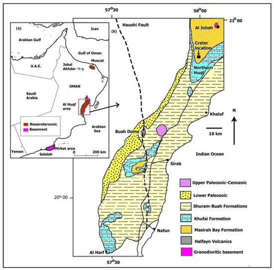
Figure 1.
(a) Map of Oman showing location of Al Huqf area in Figure 1b, (b) Geological map of Al Huqf area, showing location of the Mahout crater, modified after [34].
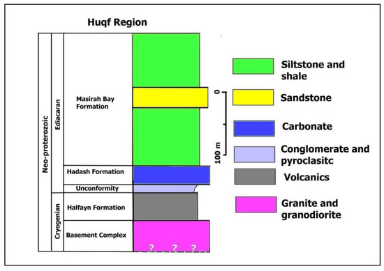
Figure 2.
Stratigraphy of rock lithology surrounding the Mahout structure, modified after [36].
Structurally, the Huqf region was affected by a series of tectonic movements that led to many important tectonic features from the Precambrian to the Cenozoic [37]. The complete exposure of Huqf rock is the result of continued deposition and faulting and uplift by these tectonics. Two closely related groups of faults were found in the Huqf area. The Cenozoic NNE-SSW faults associated with the half-dome are left lateral strike–slip faults, and the N-S sets may also be predominantly left-lateral strike–slip faults [37]. Uplifts and peneplanation occurred in the late Cretaceous (Allen and Leather, 2006 [34]). The exact age of the Mahout structure is unknown. However, the preservation of the shape and occurrence of prominent NNE Cenozoic faults that cut through the crater indicate that the crater formed after uplift and peneplanation of the Huqf region, but before Cenozoic faulting.
3. Methodology and Results
Representative samples were collected from the crater floor, rim, and ejecta along several geophysical traverses and covering all outcropping lithologies. All samples were studied under polarized and reflected microscopy. XRD analysis of rock samples was carried out at the Central Analytical and Applied Research Unit (CAARU) of the Sultan Qaboos University. Geochemical analysis was carried out using X-Ray fluorescence spectrometry (XRF) and ICP-OES at the Central Analytical and Applied Research Unit (CAARU) at the Sultan Qaboos University, and at ALS commercial Laboratories in Saudi Arabia. About 200 mg of powdered sample was weighed in screw-top Teflon autoclaves. The samples were dissolved in a HF-HNO3 mixture then evaporated to dryness on a hot plate. The cycle of acid and drying was repeated 3 or 4 times. To ensure complete dissolution, HClO4 was added during the evaporation stage. Millipore-filtered distilled water was then added. The solution was spiked with 100 ppm Ag and Ta. Three aliquots of the spiked solution were analyzed using the ICP-MS. Multi-element standards and a USGS standard were used to calibrate the ICP-MS. The precision is estimated to be 4–6% of the reported results. Detailed glasses and mineral analyses were obtained from the wave-length dispersive electron microprobe at the University of Hannover. The operating voltage for most silicates and carbonates was 15 kV, with a beam current of 12 nA and 8 nA, respectively. The counting time for common silicates was between 15 and 20 sat the peak. International standards of natural materials were used for calibration, and all data were reduced with a CITZAF procedure, except for the carbonates, where a ZAF correction was applied (geochemical and mineralogical data and methods will be the subject of future work). The detection limits and quality control of geochemical data are given in Supplementary File S1.
A geophysical survey was conducted using magnetic and gravity methods. The magnetic measurements were conducted using a GEM proton precession magnetometer, measuring every 0.2 s while the operator was walking mainly in the south–north direction, along 100 m lines with interval spacing. The gravity measurements were acquired using a CG-5 Scintrex gravimeter at stations spaced at 50 m intervals along 200 m south–northlines. Geophysical data were processed using the inversion code GRAV3D, Program Library for Forward Modelling and Inversion of Gravity Data over 3D Structures, version 6.0-2022, developed under the consortium research project Joint/Cooperative Inversion of Geophysical and Geological Data, UBC-Geophysical Inversion Facility, Department of Earth and Ocean Sciences, University of British Columbia, Vancouver, British Columbia.
3.1. Geology of Mahout Structure
Lithologies surrounding the Mahout structure are composed only of unmetamorphosed sandstone, carbonate (dolomite and limestone), shale, and silt of the Masirah Bay Formation, which is underlain with carbonate of the Hadash Formation and volcanic and basement rocks (Figure 3). The impact crater consists of an elliptical ridge about 770 m long and 550 m wide, and oriented roughly NNE to SSE (Figure 4a,b). The crater rim is 12 m high above the crater floor in the south and 20 m above the crater floor in the north and northeast periphery. At the base, the rim is 70 m in width in the north and 20 to 30 m in width in the southern and southwestern part of the crater. The rim width generally decreases by 4 to 8 m at the top. The elliptical shape and relief asymmetry indicate an oblique collision.
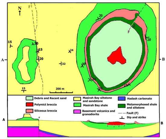
Figure 3.
Simplified geological map of the crater region and schematic E-W cross section (A–B) through the crater (vertically not to scale).
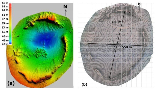
Figure 4.
(a) Orthogonal map showing variation in elevation for the rim and central breccia in the crater. (b) Contour map showing length and width of the elliptical shape crater.
The central floor of the crater is covered by a sheet of melt-bearing polymict breccias. The sheet covers an area of 150 m in diameter (Figure 5) and is comprised of small rocky hills and 1 to 2 m of breccia with variable colors, mineralogy, and textures (Supplementary File S2). The breccia contains melts and clastic material representative of all strata intersected by the crater (feldspar, carbonate, mica, hornblende, and quartz). Several carbonate–barite–celadonite dykes, 1 to 50 cm thick, cut through the breccia. Quaternary aeolian sands and broken breccia blocks of different sizes (ejecta) cover most parts of the floor. The outer crater rim is covered by a chaotic mixture and blocks of different size, composed mainly of rim and floor lithologies (quartzite, agate, and silica and polymict breccia, impact melt lapilli, and bombs). The upper part of the rim is composed mainly of quartzite and dense agate, while the base of the rim is composed of metamorphosed shale and siltstone (hornfels), underlain by non-metamorphosed shale, siltstone, and coarse-grained sandstone. The ejecta mixture forms a blanket extending just north and northeast of the structure, overlying unmetamorphosed siliciclastic rocks of the Masirah Bay Formation surrounding the crater area. The longest blanket rays extend up to 500 m in the north, northeast, and northwest directions from the crater rim. At the crater wall, the bedrock strata are inverted and fall radially outward. Different upheavals are seen on the northern and northeastern rims of the crater. The beds slope gently at 30 to 34 degrees from horizontal on the north, east, and west margins and 20 to 24 degrees on the south. The upheaval is strongest (~40 degrees) in the north and northeast. To the west of the structure is a north–south fault with an eastward plunge. A NE-SW-trending Cenozoic fault bisects the crater.
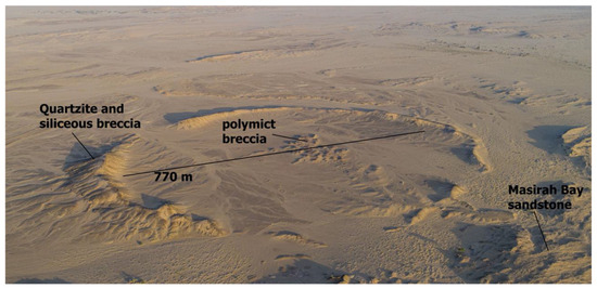
Figure 5.
A drone image showing the crater morphology and unmetamorphosed Masirah Bay sandstone surrounding the crater.
No magmatic bodies have been found in any part of the crater periphery or crater center. Most parts of the rim and center are covered with sand, and this made searching for deformation features such as shatter cones difficult. However, four samples showing shatter cone features and many samples showing ridges, grooves, striations, and streaks have been found in the micritic, sandy dolomite, and small breccia ejecta in the center and northern periphery of the crater (Figure 6a,b; Supplementary File S2). Some of these deformation features could have been covered by recent sand or eroded and abraded by the common desert wind over time.
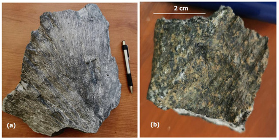
Figure 6.
(a) Shatter cones features in shocked carbonate sample. (b) Shatter cone features in a small ejecta sample (polymict breccia). Both samples show cone persasive structure.
Hydrothermal mineralization is common in the crater center and includes citrine, quartz, celadonite–carbonate aggregates, iron hydroxide, barite, and gypsum. Barite and carbonate veins trend NNE-SSW parallel to the long axis of the structure, where multiple small veins and 2–50 cm thick dykes of pegmatitic barite and calcite associated with green celadonite cut through the central part of the crater. These features indicate the presence of late-stage hydrothermal activity in the crater.
3.2. Petrology
A total of 200 representative samples of the whole crater area were collected from the Mahout structure. These include melt-bearing polymict breccia and lithic silica breccia from the crater center, and silica–iron breccia, quartzite, agate, jasper, shale–hornfels, and iron oxide/hydroxide from the crater rim and ejecta blanket (Figure 7a–d).
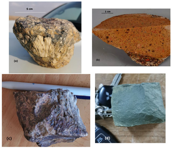
Figure 7.
(a) Ejecta of lithic silica breccia. (b) Melt-rich polymict breccia (suevite) with clasts of brown orthoclase, grey plagioclase, white carbonate, and quartz. (c) Carbonate–feldspar–quartz polymict breccia. (d) Shocked shale (hornfels).
3.2.1. Melt-Bearing Polymict Breccia from the Crater Center (Suevite)
Melt-bearing polymict breccias from the crater center are encountered in a variety of lithologies and glasses. The breccia shows variable colors ranging from all shades of gray to brown, red, and green colors. The clasts occur in variable percentages and are composed of minerals derived from rocks of the crater area (Masirah Bay sandstone, shale, silt, carbonate, and volcanic rocks and granodiorite from the basement rocks). The clast fragments have variable size (1 to 10 mm in size), angularity, and random orientations, mostly with sharp margins, and some are partially assimilated in the matrix. The following types of melt-bearing polymict breccia are found:
- Type A breccia
In hand samples, clasts of brown orthoclase and white to gray plagioclase, quartz and calcite can be observed within the matrix of these breccia. In general, feldspar (microcline and plagioclase) grains are the main constituent of this breccia. The breccia is defined by black matrix, yellow glasses, and flow textures (Figure 8). Clasts constitute about 50–60% of the breccia and comprise microcline, plagioclase, quartz, and calcite. Generally, the clasts are 1–5 mm wide and can exceed 1 cm in length. The matrix, which makes up about 40–50% of the breccia, is primarily composed of microcrystalline quartz, calcite, feldspar, and glasses (Figure 8a,b). Calcite inclusions are common within the feldspar clasts. The feldspars occur as subhedral to euhedral grains, whereas calcite and quartz occur mainly as anhedral to subhedral grains. Shock features in carbonate, quartz, and feldspar include fracturing, feather features (FFs), and planar fractures (PFs) with a width of ~1 μm and a spacing of 2–5 μm (Figure 9a,b and Figure 10a,b). Most feldspar clasts exhibit a wide range of shock features from weakly to moderately shocked. Weakly shocked feldspar clasts show irregular fractures, undulatory extinction, kink bands, while moderately shocked alkali feldspar has both planar fractures (PFs) and feature features (FFs) (Figure 11a,b), as well as diaplectic glass (an amorphous material showing the original grain boundaries of feldspar grains). Several feldspar minerals feature a darkened appearance with higher shock e.g., [38,39,40].
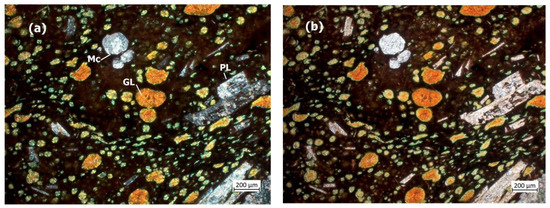
Figure 8.
(a) Photomicrograph in crossed-polarized light (xpl) and (b) plan-polarized light (ppl) of type A polymict breccia showing yellowish brown globular clasts of glasses (Gl) with flowing texture and clasts of microcline (Mc), prismatic gray plagioclase (PL), and small white grains of quartz and gray calcite.
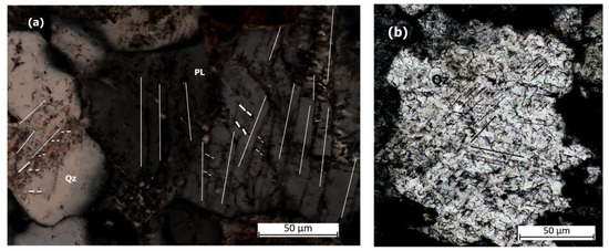
Figure 9.
(a,b) Photomicrograph in xpl showing planar fractures (PFs) and feather features (FFs) in plagiocalse (PL) and quartz (Qz). White lines are parallel to PFs ~1 μm in size and closely spaced between 2 and 5 μm. Dashed white lines are parallel to feather features. Black lines are parallel to planar fractures in (b).
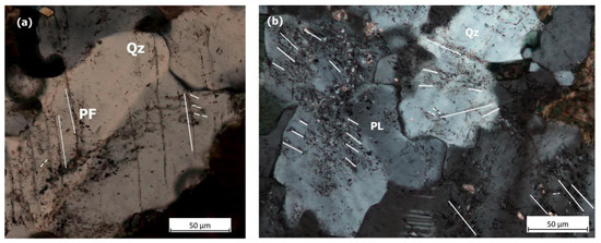
Figure 10.
(a,b) Photomicrograph in xpl showing planar fracture (PFs) and feather features (FFs) in quartz (Qz) and plagioclase (PL). White lines are parallel to planar features ~1 μm in size and closely spaced between 5 and 10 μm. Dashed white lines are parallel to feather features.
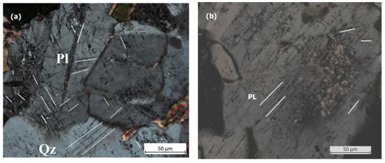
Figure 11.
(a,b) Photomicrograph in xpl showing planar fractures (PFs) and feather features (FFs) in plagioclase (PL). White lines are parallel to planar features ~1 μm in size and closely spaced between 4 and 6 μm. Dashed white lines are parallel to feather features.
- 2.
- Type B breccia
Type B breccia is defined by a brown-to-red matrix, rich in microcline and calcite clasts (Figure 12a,b). Black glasses are common only in this type of breccia (Figure 13). Clasts are 1–5 mm in size and constitute approximately 60–75% of the breccia. The matrix, which makes up about 25–40% of the breccia, is primarily composed of microcrystalline microcline, calcite, plagioclase, and black glasses, which shows a clear flow structure penetrating through calcite and feldspar grains. Calcite occurs mainly in small ocellar form (0.5 to 2 mm in diameter), as well as inclusions in feldspar. Several quartzes and plagioclases show diverging planar elements described as “feather features” [23,25]. The grains contain a planar fracture from which thin lamellae (~4–6 μm) branch off at 40–60° angles on one side. The thin and parallel lamellae that branch off from these planar fractures typically have a spacing between 2 and 10 µm. They are much shorter than the main planar fractures from which they originate. (Figure 13a,b, Supplementary File S3).
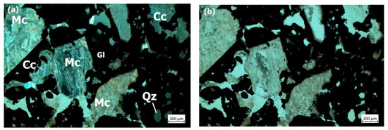
Figure 12.
Photomicrograph in xpl (a) and ppl (b) of type B polymict breccia showing black glass (Gl) in the groundmass with microcline (Mc), quartz (Qz), and calcite clasts (Cc).
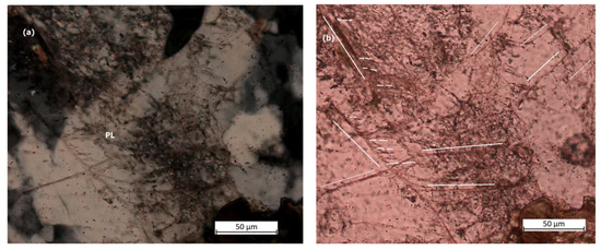
Figure 13.
Photomicrograph in xpl (a) and ppl (b) showing planar fractures (PFs) and feather features (FFs) in plagioclase (PL). White lines are parallel to planar features (PFs) and short feather features (FFs) diverging at an angle from one side of the PFs.
- 3.
- Type C Breccia
In contrast to breccia types A and B, type C breccia is generally rich in brown to dark brown glasses (0.1–1 mm in size), feldspar, and ocellar calcite (0.2–1.5 mm) (Figure 14a,b). Brown glasses are observed in various settings such as coating clasts, oblong masses, ovoids, teardrops, ribbons, or irregular fragments of various sizes within spherical clasts of calcite. The matrix, which makes up about 40–60% of the breccia, is primarily composed of microcrystalline quartz, calcite, plagioclase, orthoclase, and glasses. This breccia shows clear textural evidence of liquid immiscibility between the brown silicate glasses and carbonate, where calcite particles, in particular, take a spherical to amoeboid shape within silica glasses. Such textures, sometimes called ocellar or emulsion textures, have been observed in impact molten rocks e.g., [41]. Plagioclase clasts show PDFs and alternate twin deformation (Figure 15a,b).
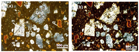
Figure 14.
Photomicrograph in xpl (a) and ppl (b) of type C polymict breccia showing brown glass (Gl), plagioclase (Pl), and calcite (Cc).
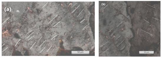
Figure 15.
(a,b) Photomicrographs in xpl showing planar fractures (PFs) in plagioclase (PL). White lines are parallel to planar features ~1 μm in size and closely spaced between 4 and 6 μm.
3.2.2. Rim Lithologies
- Lithic silica breccia (Agate–jasper Breccia)
This breccia is found mainly within the crater rim and is composed of a glass matrix and silicate components (agate, jasper, and quartzite) and iron oxide (Figure 16). Silica clasts make up about 20–70% of the breccia and consist primarily of variously colored agates, jasper, and quartzite with several hematite and goethite inclusions and spherules. The matrix is primarily composed of devitrified microcrystalline quartz (chalcedony), hematite, and vesicular white silica glasses (Figure 17). Vesicles come in various sizes and shapes, but most are spherical.
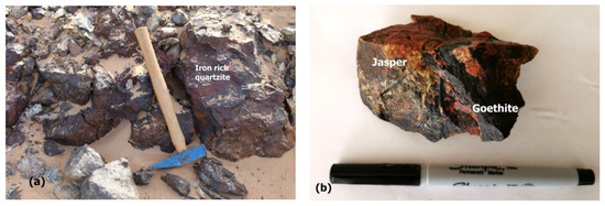
Figure 16.
Samples of lithic silica breccia. (a) Agate samples (jasper) with iron inclusions. (b) Silica breccia rich in silica clasts.
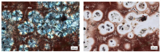
Figure 17.
Photomicrograph in xpl (a) and ppl (b) of jasper showing chalcedony (chs) cemented with Fe-rich groundmass and abundant inclusions of hematite (hm).
- 2.
- Quartzite
Quartzite is very common on the crater rim. Deformed quartz grains are the main component of quartzite. Quartz grains are usually angular or rounded and occur in monocrystalline and polycrystalline forms. Most samples show irregular fractures and wavy extinction, (Figure 18a,b). Large, well-rounded quartz grains exhibit planar and curvilinear fractures. Most crystals show sector zoning, and some shows oscillatory extinction. A fine-grained, iron-oxide-rich matrix makes up 10% of the rock, with a darker iron oxide matrix surrounding the grain boundaries.
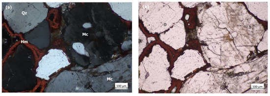
Figure 18.
Photomicrograph in xpl (a) and ppl (b) of quartzite showing angular and rounded deformed quartz grains (Qz) and microcline (Mc) cemented by hematite (Hm) and showing regular fractures.
- 3.
- Silica iron-rich breccia
The silica–iron breccia occurs mainly within the crater rim. This breccia consists mainly of a mixture of iron oxide (hematite/goethite) and small calcite and chalcedony clasts (0.5–1 mm in size) within a vesicular matrix (Figure 19a,b). Iron oxide occurs as small droplets and globules (0.1–0.5 mm in size) that form the primary matrix. Angular, rounded, unhedral micro-quartz and calcite grains make up about 50% of the breccia.
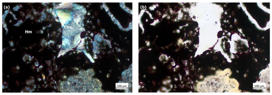
Figure 19.
Photomicrograph in xpl (a) and ppl (b) of silica–iron breccia showing chalcedony clasts (Chs) cemented by iron oxide (Hm).
- 4.
- Iron oxide
Iron oxides are mainly composed of hematite and goethite. Iron oxides are associated mainly with agate and silica breccia at the crater rim. Most samples contain vesicles with fusion crusts on the surface. Quartz grains are commonly found within iron oxides (Figure 20a,b).
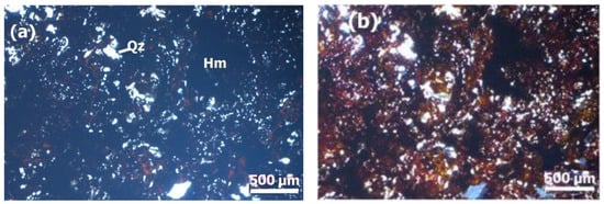
Figure 20.
Photomicrograph in xpl (a) and ppl (b) of iron oxide samples showing quartz inclusions (Qz), hematite (Hm) and abundant vesicles within iron oxide matrix.
3.3. XRD Analysis
Coesite aggregate occurs in a few breccia ejecta collected from the crater floor and rim, associated with quartz, feldspar, carbonate, and/or secondary celadonite and hematite. Coesite was identified with XRD in rock samples of silica and polymict breccia ejecta. The diffraction data were matched with the International Centre for Mineral Diffraction Data (ICCD, MineralogydatabasePDF-4/Minerals 2023, Card No. 040015-7165, Supplementary File S4). The main peaks of coesite occur at 2theta 29.26 (intensity I = 100.0), 29.97 (I = 40.6), 26.20 (I = 34.2) and 27.07 (I = 16.0) (Figure 21).
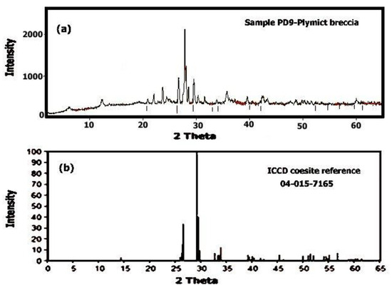
Figure 21.
(a) Representative XRD of coesite from the sample PD9 (breccia ejecta) showing coesite associated with quartz (2 theta 26.6), calcite (2 theta 29.4), and microcline (2 theta 27.24). The 2 theta of all major peaks of coesite is shown (major peaks are marked with short lines below the peaks). (b) ICCD coesite reference (2 theta values of sample and reference are given in Supplementary File S4).
3.4. Geochemistry
The average of major and trace element compositions is given in Table 1 (detailed discussion on geochemistry and mineralogy will be given in a separate work). The collected samples show variable chemical composition due to the variation in composition and percentage of clasts, melts, and target materials and possible mixing with the impactor. The mixing of the meteorite component and the target may result in a higher proportion of Fe, Ni, Co, Cu, and Zn in the target rock [42].

Table 1.
Average major and trace element analysis of crater materials.
The analyzed polymict breccia (type A, B, and C) from the crater center shows three distinct geochemical signatures and confirms the petrographic classification into type A, type B, and type C breccia. Type A and B breccia show similar SiO2 (47.2–48.7%), TiO2 (2.7–2.75 wt.%), Al2O3 (16.2–16.5 wt.%), and Na2O (2.7 wt.%). Type C breccia has lower Fe2O3 (4.5 wt.%) and MgO (2.1) than type A and type B breccia, but higher CaO (15.3 wt.%) and K2O (6.5 wt.%) than type A breccia and lower CaO than type B breccia. Type A and B breccia show higher Cr, Co, Cu, Ba, Sr, Zr, and Zn than type C breccia. The black glasses in type A breccia have the highest SiO2 content (62.4 wt.%), Al2O3 (17 wt.%), and K2O (11.9 wt.%) in comparison to the yellow glasses (type B breccia) and brown glasses (type C breccia), which show higher Fe2O3 content (8–27 wt.%). Black and brown glasses show very low TiO2 (0.01–0.4 wt.%) and CaO (0.4–0.5 wt.%). Cr, Ni, and Co are lower in the glasses than the associated clasts. Compared to silica-rich target rocks from the rim area, impact glasses and breccia rocks from the center are depleted in silica due to mixing with carbonate target rocks. A noticeable enrichment in TiO2 and CaO can be observed in the breccia impactites in the crater center. The iron-oxide-rich samples show the highest Ni and Co contents (266 and 59 ppm, respectively).
The lithic silica breccia (agate and quartzite) from the rim shows high SiO2− (87 wt.%), high Fe2O3− content (9.8 wt.%), and low Ni and Co contents, which reflects the composition of sandstone target rocks in the crater area. The silica breccia has high Cr (366 ppm) and W (167 ppm), but low Ni (23 ppm) and Co (17 ppm). The silica–iron breccia from the rim area shows intermediate composition between the lithic silica breccia and iron oxide samples, indicating mixing between the iron oxide rock and the lithic silica breccia, possibly during impact.
3.5. Hydrothermal Alteration
Field studies and microscopic observation indicate that late-stage hydrothermal alteration was caused by the interaction of water with possible hot impact-generated rocks following the formation of the crater. Hydrothermal alteration is recognized mainly within the polymict impact breccia in the central portion of the structure and within localized dykes in impact-generated concentric fault systems in the crater center. The major secondary mineral phases in the crater rocks include celadonite, quartz, calcite, dolomite, barite, goethite, hematite, and barite. The barite–calcite dykes and veins were observed cutting through the melt lenses in the crater center. Most minerals occur as aggregates of macroscopic and microscopic, radially oriented masses of euhedral crystals lining the walls of fractures and cavities. Bands of radiating barite and celadonite crystals typically form a crust on hydrothermal secondary calcite. Evidence of impact-induced hydrothermal activity has been found at numerous terrestrial impact craters e.g., [43,44,45,46,47].
3.6. Geophysical Survey
Mahout’s elliptical structure is clearly visible in the gravitational and magnetic data (Figure 22 and Figure 23). No evidence of any volcanic body underlying the crater area is indicated by the geophysical survey. A region of high induced magnetization was mapped in the center of the crater and dominated the magnetic data. This very high positive- and negative-valued anomaly (−250 nT up to 250 nT) is indicative of a body with high susceptibility values (Figure 22a). It is a strongly magnetized body, which correlates with the extension of the central crater melt-rich breccia lens. Geophysical modelling indicates that the source of the concentric magnetic anomaly lies at a shallow depth of no more than 20 m. No specific rock source was identified, but the depth rules out post-impact sediments as a source. The most plausible explanation for the magnetic anomaly may be related to structurally controlled post-impact hydrothermal alteration, which may have led to the deposition of magnetic mineral species.
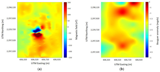
Figure 22.
Geophysical data acquired at the crater area. (a) is the map of the residual magnetic field of the Earth, (b) is the residual Bouguer anomaly map.
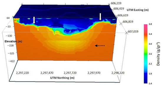
Figure 23.
Density model. The color scale is in g/cm3. View perspective from the east. White arrows indicate the crater rims and black dotted arrows indicate the possible rebound depth limit.
In addition, the gravitational exploration method imaged the elliptical shape of the crater (Figure 22b), and inversion delineated the buried strata of the crater (Figure 23). A 3D inversion of the Bouguer gravity map data showed a density variation of up to 1.9 g/cm3 (density contrast from 1.5 g/cm3 to 3.4 g/cm3, Figure 23). A low-density sand/shale layer overlies the rest of the subsurface structures. The density of this sand layer is estimated to have a value of 1.5 g/cm3 (corresponding to the dark blue color, Figure 23). A general semi-circular decrease in density from 2.5 g/cm3 to 3.3 g/cm3 in depth is observed to dominate the gravitational interval, indicating both the influence of the upper subsurface formations and the possible depression by the impact. Above 180 m depth, this effect is reversed at the center of the model (indicated by the black dotted arrow), and it is possibly connected to a rebound area due to the reaction of the rock to the impact. Both the asymmetric shape of the crater and the different burial depth of the crater rims (Figure 23, white arrows) indicate non-vertical and NE-SW faults observed in the crater area.
4. Discussion
Impact metamorphic features of the Mahout structure appear mainly in the Masirah Bay siliciclastic rocks and crater ejecta, which show different degrees of possible shock metamorphism. All samples from the crater exhibit a wide range of shock features from planar features (PFs), feather features (FFs), and shatter cones to melting and high-pressure SiO2 polymorph (coesite). However, coesite in general cannot be directly used as an exclusive impact indicator, but stishovite is the diagnostic criterion for impact origin [3]. The production of impact melt rocks and glasses is a diagnostic feature of hypervelocity impact, and their presence, distribution and characteristics have provided valuable information on the cratering process [6,48,49]. Planar and feather features in quartz are often used as diagnostic criteria of high-velocity impacts and form under high shock stresses. [12,25,48]. Melt with flow texture may indicate that the rock was melted during the shock process. The elliptical crater shape with raised edges and central melt-bearing breccia (suevite), along with common planar features and shatter cones, high-pressure minerals (coesite), and the abundant presence of crystal globules, may suggest that the structure was possibly formed by a meteorite impact.
The crater floor contains breccia and ejecta that were pushed upward from the deepest impacted levels of the crater and include representatives from all the formations intersected by the crater. Several Ni-rich iron specimens (goethite/hematite) have been identified in/or around the crater. However, no original iron meteorite specimens were found in the crater or in the surrounding area. This could indicate that the incoming impactor (likely an iron meteorite based on the high Ni and Co content in the iron oxide samples, as well as breccia samples, Table 1), of a size between 40 and 50 m in diameter (e.g., [50]; Figure 5 in [51]), experienced no fragmentation or breakup during atmospheric flight. Additionally, it may have weathered or melted and chemically and physically interacted with the shocked and melted target rocks.
The bilateral shape of the ejecta blanket is used as an indicator of the impact direction and crater impact angle in oblique impacts with impact angles < 45°. At angles < 30°, a wedge-shape forbidden zone develops uprange and a second forbidden ejecta zone develops downrange of the crater at 20°, in which the ejecta dominantly expands sideways [52,53,54]. The crater shape may also indicate the impact direction and angle, but only for impact angles < 30° [52]. Crater wall and rim profiles are usually circular for impact angles between 10 and 15° [52,55]. Craters with impact angles < 30° tend to be elliptical and elongated along the impact direction, with steeper crater walls on the uprange side of the crater, then at angles < 10°, craters become circular [52]. The crested-rim Mahout crater is blanketed with a mixture of ejecta and debris cored from the pre-existing surface. The bulk of the ejecta is preferentially concentrated in the northeastern and eastern parts of the impact area. This is consistent with the ejecta distribution, which suggests the projectile came in from the southwest [10]. The identified asymmetries, including the off-center bottom of the transient crater floor downrange, maximum overturning of target rocks along the impact direction, and lower crater rim elevation downrange, can also be diagnostic of oblique impacts e.g., [56]. Within the crater rim, unshocked shale, siltstone, and sandstone clasts are more common; further away, the shocked agate and jasper clasts dominate the area surrounding the crater. Considering the Mahout crater is essentially elliptical (Figure 4) with steep crater walls in the northeastern and eastern direction, we suggest an impact angle < 30° from the southeast direction, with a probable impact velocity of 10–12 km/s for an impact angle < 45° e.g., [57,58].
The occurrence of shatter cones, irregular fractures, and glass melt in the breccia and rock ejecta may indicate different shock stages, which range from weak to moderately shocked. Based on the shock texture in quartz, calcite, and feldspar, several classification systems for estimating the shock level in deformed samples were developed e.g., [39,40,59,60,61]. Weakly shocked feldspars develop irregular fractures and undulatory extinction, and their shock pressure (SP) is estimated to be ~5 to ~14 GPa and post-shock temperature (PST) ~100 °C. Moderately shocked feldspars show both PDFs and isotropic twinning lamellae and isotropic spots (diaplectic and glass), which indicates the shock stage of SP and PST is from ~32 to ~45 GPa and 300 to 900 °C, respectively. Strongly shocked feldspar glass indicates a shock pressure of 45–60 GPa and post-shock temperature between 900 and 1500 °C [59,61]. In sandstones, shock melting of individual quartz grains starts at pressures as low as approximately 5 GPa and whole-rock melting occurs above approximately 30–35 GPa [62,63]. The deformation features in the Mahout crater rocks include mainly planar fractures (PFs) and feather features (FFs) in quartz and felspar, which is consistent with low shock levels of ~5 to ~14 GPa. Feather features developed in quartz indicate shock pressure approximately 7–10 GPa [25], therefore in the lower portion of the shock metamorphism regime.
The alternative origins that could generate sub-elliptical crater-like features similar to the Mahout structure include salt domes, collapsed volcanic calderas, and tectonic deformation, or a combination of these processes e.g., [64]. Salt dome collapse can result in circular depressions with strongly developed radial faults [65]. The salt domes of Oman belong to the Ara Formation (Lower Cambrian). There is no evidence of salt domes cutting through Proterozoic strata in the Mahout crater area [32,33]. Furthermore, salt domes lack the lithic and polymict breccia, crater rim, and ejecta observed at the Mahout crater. Fault deformation can form small rhombohedral to elliptical basins bounded by extensional faults [66]. However, these basins are rarely circular and often have a length/width ratio >2 [66]. The aspect ratio in the Mahout crater is close to 1. and the presence of the crater rim and melt-bearing breccia in a small area of the crater floor are inconsistent with a fault origin. Deep-seated faults cannot be the source of the high-temperature and-pressure metamorphism observed within breccia clasts and the thick rim of the crater. No mylonitic rocks, usually associated with faults, have been identified within the crater lithologies.
The most consistent origin of the Mahout crater with local geology is that it may have formed with volcanic activity. There is evidence of small eruptions of Cambro-Ordovician alkaline volcanic lava near Khalouf and Sirab village (Figure 1), south of the crater area [67]. However, these volcanic rocks are massive and have no breccia or melts. They are ultrabasic in composition, and do not form any crater structures [67]. No remains of any types of volcanic bodies have been found within any part of the 30 to 70 m thick metamorphosed crater rim. The rim is underlain by unmetamorphosed shale, siltstones, and sandstones, and no salt or iron ore bodies were observed underlying the crater through the field verifications and geophysical survey. The sandstone, silt, and shale of the target rocks have been highly deformed and metamorphosed to quartzite, highly compacted and deformed agate, and jasper breccia. Also, highly heterogenous breccia, heterogenous rocks and glass composition, and variable textures are not common in small volcanic craters. Besides the geophysical evidence of the absence of any volcanic body below the crater, this makes the volcanic origin of the Mahout crater unlikely. There are no other features in the central desert of Oman, in the salt basin area in central and south Oman, or in the small volcanic outcrops of the central desert that are morphologically similar to the Mahout crater. Collapsed salt domes, volcanoes, and deep-seated faults can be excluded as origins of formation of the Mahout structure.
The exact age of the crater is unknown. However, the crater shape and ejecta patterns suggest formation through a northeasterly impact during the late Cretaceous to early Cenozoic, after uplift and peneplanation of the central desert region of Oman during the late Cretaceous and before Cenozoic faulting, which cuts through the crater area. Given the suspected late Cretaceous–early Cenozoic age of the crater, its long-term survival in the desert area is likely due to the relative hardness of the metamorphosed agate and quarzitic rock that mantles the crater rims and resistance to erosion and transport by the wind. Impact events at the K-Pg boundary include the 66 Ma old Chicxulub crater [68], the Nadir crater, West Africa [69], and the Boltysh impact structure [70]. The Mahout crater could be related to these K-Pg impact events.
The Mahout structure is best classified as a‘mixed targets’ type crater as it formed on impact with both crystalline and sedimentary rocks. A wide range of impact-generated lithologies have been described for impact craters formed in so-called ‘mixed targets’ (i.e., crystalline basement overlain by sedimentary rocks). The differences in composition and temperature of melts from different lithologies in mixed siliciclastic–carbonate–acidic volcanics–granodiorite targets results in unmixed and heterogeneous melt-bearing products e.g., [3,46,47]. Deformed impact melts from mixed-target craters are characterized by centimeter-sized glass particles in whole-rock impact melts. These glasses originate primarily from the crystalline fraction of the target [21,71].
All current analyses suggest the impact origin of the Mahout structure; however, further work is needed to better constrain the Mahout structure for its possible impact origin, in order to add it to the impact database and make it fully proven.
The Ministry of Heritage and Tourism in Oman is planning to establish a geopark in the central desert of Oman. The Mahout crater could be an interesting and important geosite within the proposed geopark area.
5. Conclusions
This study presents the results of geological, petrological, and geophysical investigations of metamorphosed rocks from the Mahout structure in central Oman. The results of this study indicate the following:
- The Mahout structure can be recognized as the first possible impact structure Oman, based on the occurrence of shatter cones and the presence of shock deformation features in quartz, feldspar, and calcite clasts in several rock samples.
- The structure was formed in mixed sedimentary–igneous strata of late Proterozoic age (sandstones, siltstones, shales, carbonate, and volcanic and basement rocks).
- The structure has most features of a simple impact crater associated with an oblique impact (<30°), such as sub-elliptical bowl shape, the ejecta blanket distribution (extending to the immediate northeast and east of the structure with a bilateral shape), high-pressure minerals (coesite) and deformation features (common planar fractures (PFs), feather features (FFs), and shatter cones),melt-rich polymict breccia, and metamorphosed rim lithologies.
- The date of the crater-forming impact event is estimated to be during the K-Pg, based on the late Cretaceous age proposed for the peneplanation of the central desert of Oman and Cenozoic faulting cutting through the crater area.
- No traces of meteoritic material have been found so far.
- Alternative source processes such as salt dome, volcanic, and tectonic origin of the Mahout structure can be excluded as its origin of formation.
All current analyses suggest the impact origin of the Mahout structure; however, further studies are required to give a definite answer, and this must include extensive study of PDFs in quartz and feldspar with the universal stage, further search and description of shatter cones, in-depth geophysical survey of the area (seismic and resistivity), and analyses of minerals and quartz polymorphs (e.g., stishovite) and other shock features.
Supplementary Materials
The following supporting information can be downloaded at: https://www.mdpi.com/article/10.3390/geosciences13120363/s1, File S1: Detection limit and quality control of geochemical data; File S2: Field images; File S3: Deformation Features; File S4: ICCD reference data of coesite.
Author Contributions
S.N.: field work, petrology, mineralogy, and writing the manuscript; N.E. and K.A.H.: geophysical survey, field work, writing; T.A.H., S.S. and B.S.: field work. All authors have read and agreed to the published version of the manuscript.
Funding
Deanship of Research Internal grant- Sultan Qaboos University grant number IG/SCI/ETHS/24/01.
Data Availability Statement
Data can be requested by e-mailing the first author.
Acknowledgments
The authors are grateful to the helpful and constructive reviews of three reviewers and the excellent editorial handling of Assistant Editor. The authors are thankful to Bader Al Shaqsi, Salim Al- Rawas, Ammar Al Kiyumi, and Arshad Ali for their help in the field work.
Conflicts of Interest
Authors Sean Spratley and Brian Spratley were employed by the company Knights Bay Mining. The remaining authors declare that the research was conducted in the absence of any commercial or financial relationships that could be construed as a potential conflict of interest.
References
- Engelhardt, W.V. Distribution, petrography and shock metamorphism of the ejecta of the Ries crater in Germany—A review. Tectonophysics 1990, 171, 259–273. [Google Scholar] [CrossRef]
- Engelhardt, W.V. Suevite breccia of the Ries impact crater, Germany: Petrography, chemistry and shock metamorphism of crystalline rock clasts. Meteorit. Planet. Sci. 1997, 32, 545–554. [Google Scholar] [CrossRef]
- Osinski, G.R.; Grieve, R.A.F.; Ferrière, L.; Losiak, A.; Pickersgill, A.E.; Cavosie, A.J.; Hibbard, S.M.; Hill, P.J.A.; Bermudez, J.J.; Marion, C.L.; et al. Impact earth: A review of the Terrestrial Impact Record. Earth-Sci. Rev. 2022, 232, 104112. [Google Scholar] [CrossRef]
- Impact Crater Database: November 2023. Available online: www.passc.net/EarthImpactDatabase/ (accessed on 23 October 2023).
- Bland, P.A.; Artemieva, N.A. The rate of small impacts on Earth. Meteorit. Planet. Sci. 2006, 41, 607–631. [Google Scholar] [CrossRef]
- Dence, M.R. The extraterrestrial origin of Canadian craters. Ann. N. Y. Acad. Sci. 1965, 123, 941–969. [Google Scholar] [CrossRef]
- Dence, M.R. The nature and significance of terrestrial impact structures. Int. Geol. Congr. Proc. 1972, 24, 77–89. [Google Scholar]
- Halliday, I.; Griffin, A.A.; Blackwell, A.T. Detailed data for 259 fireballs from the Canadian camera network and inferences concerning the influx of large meteoroids. Meteorit. Planet. Sci. 1996, 31, 185–217. [Google Scholar] [CrossRef]
- Nemtchinov, I.V.; Svetsov, V.V.; Kosarev, I.B.; Golub’, A.P.; Popova, O.P.; Shuvalov, V.V.; Spalding, R.E.; Jacobs, C.; Tagliaferri, E. Assessment of kinetic energy of meteoroids detected by satellite-based light sensors. Icarus 1997, 130, 259–274. [Google Scholar] [CrossRef]
- Kenkmann, T.; Poelchau, M.; Wulf, G. Structural geology of impact craters. J. Struct. Geol. 2014, 62, 156–182. [Google Scholar] [CrossRef]
- Morbidelli, A.; Jedicke, R.; Bottke, W.F.; Michel, P.; Tedesco, E.F. From magnitudes to diameters: The albedo distribution of near Earth objects and the Earth collision hazard. Icarus 2002, 158, 329–342. [Google Scholar] [CrossRef]
- French, B.M.; Cordua, W.S.; Plescia, J. The Rock Elm meteorite impact structure, Wisconsin: Geology and shock-metamorphic effects in quartz. Geol. Soc. Am. Bull. 2004, 116, 200–218. [Google Scholar] [CrossRef]
- Ferriere, L.; Morrow, J.R.; Amgaa, T.; Koeberl, C. Systematic study of universal-stage measurements of planar deformation features in shocked quartz: Implications for statistical significance and representation of results. Meteorit. Planet. Sci. 2009, 44, 925–940. [Google Scholar] [CrossRef]
- Losiak, A.; Wild, E.M.; Huber, M.S.; Wisniowski, T.; Paavel, K.; Joeleht, A.; Välja, R.; Plado, J.; Kriiska, A.; Wilk, J.; et al. Dating Kaali Crater (Estonia) based on Charcoal emplaced within proximal ejecta blanket. Meteorit. Planet. Sci. 2016, 51, 681–695. [Google Scholar] [CrossRef]
- Losiak, A.; Jõeleht, A.; Plado, J.; Szyszka, M.; Kirsimäe, K.; Wild, E.M.; Steier, P.; Belcher, C.M.; Jazwa, A.M.; Helde, R. Determining the age and possibility for an extraterrestrial impact formation mechanism of the Ilumetsa structures (Estonia). Meteorit. Planet. Sci. 2020, 55, 274–293. [Google Scholar] [CrossRef]
- Losiak, A.; Belcher, C.M.; Plado, J.; Jõeleht, A.; Herd, C.D.K.; Kofman, R.S.; Szokaluk, M.; Szczuciński, W. Small impact cratering processes produce distinctive charcoal assemblages. Geology 2022, 50, 1276–1280. [Google Scholar] [CrossRef]
- French, B.M. Sudbury structure, Ontario: Some petrographic evidence for an origin by meteorite impact. In Shock Metamorphism of Natural Materials; French, B.M., Short, N.M., Eds.; Mono Book Corporation: Baltimore, MD, USA, 1968; pp. 383–412. [Google Scholar]
- Stöffler, D. Deformation and transformation of rock-forming minerals by natural and experimental shock processes: II. Physical properties of shocked minerals. Fortschr. Miner. 1974, 51, 256–289. [Google Scholar]
- Von Engelhardt, W.; Stoffler, D. Stages of shock metamorphism in crystalline rocks of the Ries Basin, Germany. In Shock Metamorphism of Natural Materials; French, B.M., Short, N.M., Eds.; Mono Book Corporation: Baltimore, MD, USA, 1968; pp. 159–168. [Google Scholar]
- Stöffler, D.; Langenhorst, F. Shock metamorphism of quartz in nature and experiment: I. Basic observation and theory. Meteoritics 1994, 29, 155–181. [Google Scholar] [CrossRef]
- Grieve, R.A.F.; Pilkington, M. The signature of terrestrial impacts. J. Aust. Geol. Geophys. 1996, 16, 399–420. [Google Scholar]
- French, B.M. Traces of Catastrophe: A Handbook of Shock-Metamorphic Effects in Terrestrial Meteorite Impact Craters; Contribution CB-954; Lunar and Planetary Institute: Houston, TX, USA, 1998; p. 120. [Google Scholar]
- French, B.M.; Koeberl, C. The convincing identification of terrestrial meteorite impact structures: What works, what doesn’t, and why. Earth-Sci. Rev. 2010, 98, 123–170. [Google Scholar] [CrossRef]
- Glikson, A.; Uysal, I.T.; Gerald, J.D.F.; Sayg, E. Geophysical anomalies and quartz microstructures, Eastern Warburton Basin, North-east South Australia: Tectonic or impact shock metamorphic origin? Tectonophysics 2013, 589, 57–76. [Google Scholar] [CrossRef]
- Poelchau, M.H.; Kenkmann, T. Feather features: A low-shock-pressure indicator in quartz. J. Geophys. Res. 2011, 116, B02201. [Google Scholar] [CrossRef]
- Levell, B.; Richard, P.; Hoogendijk, F. Apossible Albian impact craterat Murshid, southern Oman. GeoArabia 2002, 7, 721–730. [Google Scholar] [CrossRef]
- Olds, P. Evidence in Oman for Mantle Excavating Hypervelocity Impact at the Cenomanian-Turonian Boundary? Acta Geol. Sin. 2020, 4 (Suppl. S1), 44. [Google Scholar] [CrossRef]
- Kenkmann, T.; Afifi, A.; Stewart, S.; Michael HPoelchau, M.; Cook, D.; Nevelle, A. Saqqar: A 34 km diameter impact structure in Saudi Arabia. Meteorit. Planet. Sci. 2015, 50, 1925–1940. [Google Scholar] [CrossRef]
- Prescott, J.R.; Robertson, G.B.; Shoemaker, C.; Shoemaker, E.M.; Wynn, J. Luminescence dating of the Wabar meteorite craters, Saudi Arabia. J. Geophys. Res. 2004, 109, 1–8. [Google Scholar] [CrossRef]
- Fazio, A.; Folco, A.; D’Orazio, M.; Frezzotti, M.; Cordier, C. Shock metamorphism and impact melting in small impact craters on Earth: Evidence from Kamil crater, Egypt. Meteorit. Planet. Sci. 2014, 49, 2175–2200. [Google Scholar] [CrossRef]
- Kenkmann, T.; Sturm, S.; Krüger, T.; Salameh, E.; Al-Raggad, M.; Konsul, K. The structural inventory of a small complex impact crater: Jebel Waqf as Suwwan, Jordan. Meteorit. Planet. Sci. 2017, 52, 1351–1370. [Google Scholar] [CrossRef]
- Loosveld, R.; Bell, A.; Terken, J. The tectonic evolution of interior Oman. GeoArabia 1996, 1, 28–51. [Google Scholar] [CrossRef]
- Reuning, L.; Shoenherr, J.; Hermann, A. Constraints on the diagenesis, stratigraphy and internal dynamics of the surface-piercing salt domes in the Ghaba Salt Basin (Oman): A comparison to the Ara Group in the South Oman Salt Basin. GeoArabia 2009, 14, 83–120. [Google Scholar] [CrossRef]
- Allen, P.A.; Leather, J. Post-Marinoan marine siliciclastic sedimentation: The Masirah Bay Formation, Neoproterozoic Huqf Supergroup of Oman. Precambrian Res. 2006, 144, 167–198. [Google Scholar] [CrossRef]
- Allen, P.A.; Leather, J.; Brasier, M.D. The Neoproterozoic Fiq glaciation and its aftermath, Huqf Supergroup of Oman. Basin Res. 2004, 16, 507–534. [Google Scholar] [CrossRef]
- Rieu, R.; Allen, P.A.; Cozzi, A.; Kosler, J.; Bussy, F. A composite stratigraphy for the Neoproterozoic Huqf Supergroup of Oman: Integrating new litho-, chemo- and chronostratigraphic data of the Mirbat area, southern Oman. J. Geol. Soc. 2007, 164, 997–1009. [Google Scholar] [CrossRef]
- Dubreuilh, J.; Platel, J.P.; Le M’etour, J.; Roger, J.; Wyns, R.; Bechennec, F.; Berthiaux, A. Geological Map of Khaluf, Sheet NF 40-15, Scale 1:250,000; Directorate General of Minerals, Oman Ministry of Petroleum and Minerals: Muscat, Oman, 1992. [Google Scholar]
- Jaret, S.J.; Kah, L.C.; Harris, R.S. Progressive deformation of feldspar recording low-barometry impact processes, Tenoumer impact structure, Mauritania. Meteorit. Planet. Sci. 2014, 49, 1007–1022. [Google Scholar] [CrossRef]
- Jaret, S.J.; Johnson, J.R.; Sims, M.; DiFrancesco, N.; Glotch, T.D. Microspectroscopic and petrographic comparison of experimentally shocked albite, andesine, and bytownite. J. Geophys. Res. 2018, 123, 1701–1722. [Google Scholar] [CrossRef]
- Pickersgill, A.E.; Jaret, S.J.; Pittarello, L.; Fritz, J.; Harris, R.S. Shock effects in feldspars: An overview. In Large Meteorite Impacts and Planetary Evolution VI; Reimold, W.U., Koeberl, C., Eds.; Geological Society of America: Boulder, CO, USA, 2021; Volume 550, pp. 507–535. [Google Scholar]
- Graup, G. Carbonate-silicate liquid immiscibility upon impact melting: Ries Crater, Germany. Meteorit. Planet. Sci. 1999, 34, 425438. [Google Scholar] [CrossRef]
- Mittlefehldt, D.W.; Horz, F.; See, T.H.; Scott, E.R.D.; Mertzman, S.A. Geochemistry of target rocks, impact melt particles, and metallic spherules from Meteor Crater, Arizona: Empirical evidence on the impact process. Geol. Soc. Am. Spec. Pap. 2005, 384, 367–390. [Google Scholar]
- Hagerty, J.J.; Newsom, H.E. Hydrothermal alteration at the Lonar Lake impact structure, India: Implications for impact cratering on Mars. Meteorit. Planet. Sci. 2003, 38, 365–381. [Google Scholar] [CrossRef]
- Naumov, M.V. Principal features of impact-generated hydrothermal circulation systems: Mineralogical and geochemical evidence. Geofluids 2005, 5, 165–184. [Google Scholar] [CrossRef]
- Osinski, G.R.; Spray, J.G. Impact-generated carbonate melts: Evidence from the Haughton Structure, Canada. Earth Planet. Sci. Lett. 2001, 194, 17–29. [Google Scholar] [CrossRef]
- Osinski, G.R.; Lee, P.; Spray, J.G.; Parnell, J.; Lim, D.S.S.; Bunch, T.E.; Cockell, C.S.; Glass, B.J. Geological overview and cratering model for the Haughton impact structure, Devon Island, Canadian High Arctic. Meteorit. Planet. Sci. 2005, 40, 1759–1776. [Google Scholar] [CrossRef]
- Osinski, G.; Grieve, R.; Collins, S.; Marion, C.; Sylveter, P. The effect of target lithology on the products of impact melting The effect of target lithology on the products of impact melting. Meteorit. Planet. Sci. 2008, 43, 1939–1954. [Google Scholar] [CrossRef]
- Grieve, R.A.F.; Dence, M.R.; Robertson, P.B. Cratering processes: As interpreted from the occurrences of impact melts. In Impact and Explosion Cratering; Roddy, D.J., Pepin, R.O., Merrill, R.B., Eds.; Pergamon Press: New York, NY, USA, 1977; pp. 791–814. [Google Scholar]
- Grieve, R.A.F.; Cintala, M.J. An analysis of differential impact melt-crater scaling and implications for the terrestrial impact record. Meteoritics 1992, 27, 526–538. [Google Scholar] [CrossRef]
- Hughes, D.W. The approximate ratios between the diameters of terrestrial impact craters and the causative incident asteroids. Mon. Not. R. Astron. Soc. 2003, 338, 999–1003. [Google Scholar] [CrossRef][Green Version]
- Marchia, S.; Barbieria, C.; Kueppers, M.; Marzaric, F.; Davidssond, B.; Keller, H.U.; Besse, S.P.; Lamy, F.; Mottolag, S.; Massironih, M.; et al. The Cratering History of Asteroid (2867) Steins. Planet. Space Sci. 2010, 58, 1116–1123. [Google Scholar] [CrossRef][Green Version]
- Gault, D.E.; Wedekind, J.A. Experimental studies of oblique impact. In Proceedings of the 9th Lunar and Planetary Science Conference, Houston, TX, USA, 13–17 March 1978; pp. 3843–3875. [Google Scholar]
- Herrick, R.R.; Forsberg-Taylor, N.K. The shape and appearance of craters formed by oblique impact on the Moon and Venus. Meteorit. Planet. Sci. 2003, 38, 1551–1578. [Google Scholar] [CrossRef]
- Herrick, R.R.; Hessen, K.K. The planforms of low-angle impact craters in the northern hemisphere of Mars. Meteor. Planet. Sci. 2006, 41, 1483–1495. [Google Scholar] [CrossRef]
- Bottke, W.F.; Love, S.G.; Tytell, D.; Glotch, T. Interpreting the elliptical crater populations on Mars, Venus, and the Moon. Icarus 2000, 145, 108–121. [Google Scholar] [CrossRef]
- Poelchau, M.H.; Kenkmann, T. Asymmetric signatures in simple craters as an indicator for an oblique impact direction. Meteorit. Planet. Sci. 2008, 43, 2059–2072. [Google Scholar] [CrossRef]
- Bryan, J.B.; Burton, D.E.; Lettis, L.A.; Morris, L.K.; Johnson, W.E. Calculations of Impact Crater Size Versus Meteorite Velocity. Lunar Planet. Sci. XI P 1980, 11, 112–114. [Google Scholar]
- Melosh, H.; Collins, G. Meteor Crater formed by low-velocity impact. Nature 2005, 434, 157. [Google Scholar] [CrossRef]
- Stöffler, D. Progressive metamorphism and classification of shocked and brecciated crystalline rocks at impact craters. J. Geophys. Res. 1971, 76, 5541–5551. [Google Scholar] [CrossRef]
- Stöffler, D. Deformation and transformation of rock-forming minerals by natural and experimental shock processes: I. Behavior of minerals under shock compression. Fortschr. Mineral. 1972, 49, 50.e113. [Google Scholar]
- Stöffler, D.; Hamann, C.; Metzler, K. Shock metamorphism of planetary silicate rocks and sediments: Proposal for an updated classification system. Meteorit. Planet. Sci. 2018, 53, 5–49. [Google Scholar] [CrossRef]
- Kieffer, S.W.; Phakey, P.P.; Christie, J.M. Shock processes in porous quartzite: Transmission electron microscope observations and theory. Contrib. Mineral. Petrol. 1976, 59, 41–93. [Google Scholar] [CrossRef]
- Kowitz, A.; Guldemeister, N.; Reimold, W.U.; Schmitt, R.T.; Wunnemann, K. Diaplectic quartz glass and SiO2 melt experimentally generated at only 5 GPa shock pressure in porous sandstone: Laboratory observations and meso-scale numerical modeling. Earth Planet. Sci. Lett. 2013, 384, 17–26. [Google Scholar] [CrossRef]
- McDonnell, A.; Loucks, R.G.; Dooley, T. Quantifying the origin and geometry of circular sag structures in northern Fort Worth Basin, Texas: Paleocave collapse, pull-apart fault systems, or hydrothermal alteration? AAPG Bull. 2007, 91, 1295–1318. [Google Scholar] [CrossRef]
- Bertoni, C.; Cartwright, J. 3D seismic analysis of circular evaporite dissolution structures, Eastern Mediterranean. J. Geol. Soc. 2005, 162, 909–926. [Google Scholar] [CrossRef]
- Stewart, S. Seismic interpretation of circular geological structures. Pet. Geosci. 1999, 5, 273–285. [Google Scholar] [CrossRef]
- Worthing, M.; Nasir, S. Cambro-Ordovician potassic (alkaline) magmatism in Central Oman: Petrological and geochemical constraints on petrogenesis. Lithos 2008, 106, 25–38. [Google Scholar] [CrossRef]
- Schulte, P.; Alegret, L.; Arenillas, I.; Arz, J.A.; Barton, J.; Bown, P.R.; Bralower, T.J.; Christeson, G.L.; Claeys, P.; Cockell, C.S. The Chicxulub asteroid impact and mass extinction at the Cretaceous-Paleogene boundary. Science 2010, 327, 1214–1218. [Google Scholar] [CrossRef]
- Nicholson, Y.; Bray, V.; Gulick, S.P.; Aduomahor, B. The Nadir Crater offshore West Africa: A candidate Cretaceous-Paleogene impact structure. Sci. Adv. 2022, 8, eabn3096. [Google Scholar] [CrossRef] [PubMed]
- Pickersgill, A.E.; Mark, D.F.; Lee, M.R.; Kelley, S.P.; Jolley, D.W. The Boltysh impact structure: An early Danian impact event during recovery from the K-Pg mass extinction. Sci. Adv. 2021, 7, eabe6530. [Google Scholar] [CrossRef] [PubMed]
- Pilkington, M.; Grieve, R.A.F. The geophysical signature of terrestrial impact craters. Rev. Geophys. 1992, 30, 161–181. [Google Scholar] [CrossRef]


Disclaimer/Publisher’s Note: The statements, opinions and data contained in all publications are solely those of the individual author(s) and contributor(s) and not of MDPI and/or the editor(s). MDPI and/or the editor(s) disclaim responsibility for any injury to people or property resulting from any ideas, methods, instructions or products referred to in the content. |
© 2023 by the authors. Licensee MDPI, Basel, Switzerland. This article is an open access article distributed under the terms and conditions of the Creative Commons Attribution (CC BY) license (https://creativecommons.org/licenses/by/4.0/).