Abstract
The cavities or lava tubes in the Galapagos Islands were formed by the differential cooling of the basaltic flow of the volcanoes surrounding these islands. In this article, a stability analysis was carried out to determine the degree of safety of different lava tubes using three methods: two empirical ones based on geomechanical classifications and one strain–strain (Hoek–Brown failure criterion). The methodology used consisted of the following phases: (i) compilation of information based on existing geomechanical mapping; (ii) geomechanical classification of the rock mass using Barton’s Q index and rock mass rating; (iii) steady state qualification using the geotechnical index of cavities (GCI); (iv) numerical modeling applying the Hoek–Brown criterion; (v) comparison of methodology and discussion of the results. The data obtained indicate that the methodologies used to evaluate the stability of the lava tubes have high reliability since they allowed the characterization of the different lava tubes. As the final “product” of the investigation, a graph was drawn up in which the empirical observations and the safety factors obtained with the numerical analysis (stress–strain) were superimposed, classifying the lava tubes as stable and non-stable. It can be concluded that the characterization methodologies used in this article can be applied to similar cases and fill a gap in rapid preliminary analyses of the degree of stability and risk of cave collapse.
1. Introduction
Caves have always been a fundamental part of the development of civilization since the first humans who inhabited planet earth were housed in them [1]. In recent years, caves have become tourist attractions because of their surroundings and the wide variety of materials that usually exist inside them.
The Galapagos Islands are one of the most internationally recognized tourist destinations, given their great diversity of fauna, flora, and caves of volcanic origin, for which they have been declared a World Heritage Site since 1979 [2].
These 13 islands were generated by a hotspot with a genesis similar to the Hawaiian Islands [3]. Several shield-shaped volcanoes on the islands are currently inactive [4,5]. The main products of the eruptive activity are pahoehoe-type or AA-type lava flows [6]. The differential cooling of the basaltic magma flow has locally originated cavities of the length of kilometers and metric height, known as lava tubes [7]. Currently, the development of the urbanization of the Galapagos Islands is at its peak. Therefore, new stability studies of the existing cavities are needed.
Recently, various studies [8,9,10,11] have analyzed the danger of lateral eruptions and recreated zoning maps according to the level of danger in caves and lava tunnels. These stability analyses are fundamental since the caves are visited by tourists and by researchers (archaeologists and paleontologists).
Geomechanical classifications and empirical methods can evaluate the stability of lava tubes. These techniques consist of a set of numerical values assigned to the rock mass, which, seen from an engineering point of view, can quantify and assess the stability of tunnels, mines, and caves without supports, among other kinds of underground cavities [12]. The most widely used geomechanical classification methods are Barton’s Q index [13,14] and the rock mass rating (RMR) [15,16], which have been applied around the world to evaluate the stability of underground engineering works. These classification methods are acceptable for evaluating the stability of underground caves and have undergone slight modifications over time [17,18,19,20].
The RMR geomechanical classification [15,21] defines and rates the rock mass as one of five classes based on structural geology and strong characterization. This arrangement is made by considering the sum of six main factors: the uniaxial compressive strength of the rock material, the rock quality designation (RQD) value, the spacing between joints, the state of the joints, and the presence of groundwater. The Q index is the most popular classification to analyze underground excavations (tunnels and mines) and in this investigation, it is applied to cave stability [1].
The integrity of the caves is evaluated by means of the Cave Geomechanical Index (CGI) [22]. This model considers the combination of four variables: (i) rock mass rating (RMR), (ii) hydraulic radius (RH), (iii) ceiling shape (CS), and (iv) ceiling thickness (CT). Each of these variables has an assigned weight, which is added according to the numerical ranges or intervals obtained from the analysis of the massif.
In this research, we compared the width of the caves and the Q index [12], where a function was determined to establish whether a cave is stable or unstable. The stability of lava caves in the Mirador and Bellavista sectors of Santa Cruz Island (Galapagos) was analyzed using three geomechanical classification methods (RMR, Q index, and CGI) to evaluate the tunnels’ capacity for supporting vertical loads.
2. Materials and Methods
This research was carried out in the Mirador cave located in the Mirador sector and the Gallardo and Galla-Zoila caves located in the Bellavista sector of the Santa Cruz Islands (Figure 1). In each of these caves, the following procedure was implemented.
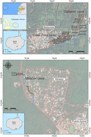
Figure 1.
Location of the Galapagos Islands and the studied lava tubes (Mirador cave and Bellavista sector).
- Visit the cave for: geometric data, geomechanical station to determine the simple compression of the rock, discontinuity properties, quality index, and Geological Strength Index (GSI). Observation and data collection of eventual instabilities.
- Cabinet work for:
- 2.1.
- Determination of the massif quality indices: RMR, Q, and CGI;
- 2.2.
- Determination of the properties of the massif as a continuous medium: Hoek–Brown generalized criterion [23,24];
- 2.3.
- Elaboration of stress–strain models by numerical modeling using boundary elements;
- 2.4.
- Discussion and comparison of results.
The acronyms used in the text are resumed at the end of the text in Table 9. The researchers obtained geomechanical mapping information primarily by locating and characterizing lava tunnels. The existing space in the underground natural cavities was determined, and a graphic representation of the tunnels’ geometry was made. Local information surveys were carried out to locate all the entrances to the tunnels and previous to this investigation there was another research study that undertook topographical, geological, volcanological, and geophysical (seismic, radar, and electrical) surveys (which are not the scope of this investigation). This previous research brought information about cave position, roof thickness, dimensions, and some basic rock mass properties (such as seismic velocity, joint persistence, etc.). Then, the geomechanics of the rocky material, including the determination of the physical–mechanical properties of the intact rock, were characterized. The geomechanical mapping was also carried out at different stations within the tunnels to collect the degree of weathering, presence of groundwater, spacing, orientation of discontinuities, and state of joint parameters. Finally, the area was zoned according to the degree of danger due to the existence of lava tunnels.
The geomechanical classification of the rock mass was determined according to 3 classifications: rock mass rating (RMR), Q index, and Cave Geomechanical Index (CGI). To obtain the input parameters we followed the methodology of “geomechanical stations”. A geomechanical station is a set of observations and measures of the orientation of discontinuities, rock strength (using the hammer of a sclerometer), and condition of joints (persistence, roughness, and infilling) using field “notebooks” and templates. Once each relevant parameter was obtained, then the rating of them was calculated using the tables and criteria of each system RMR, Q, or CGI. It is important to notice that the ratings of each rock mass classification are developed in tables with a range of values for key parameters. It cannot be developed due to extension in this text, and it can be consulted in the references of each of the systems.
- Geomechanical classification of the rock mass using Barton’s Q index and RMR [15]
The RMR and Q Barton index classification systems were used to determine the quality of the rock mass. Thus, geologists, engineers, and builders could establish a common language.
- Cave steady state qualification using CGI
Another method of geomechanical characterization of caves used to evaluate the susceptibility to structural instability is the CGI. This parameter indicates the existing geomechanical qualities in the rock.
The CGI is a combination of four variables:
(i) RMR, the Bieniawski geomechanical classification [23], allows the evaluation of the quality of the rock mass. The variables involved in this parameter are assigned a numerical weight, and the sum results in a geomechanical assessment. This rock mass geomechanical quality classification system is divided into five classes, whose values are input parameters within the geotechnical index of cavities, as detailed in Table 1.

Table 1.
Rock mass rating (RMR) according to [15] was used in the CGI.
(ii) Hydraulic radius—a parameter that results from the ratio between the area and perimeter of the cave. This parameter, described in Table 2, was initially used in fluid dynamics. However, it has also been used for stability analyses of underground structures since 1977 by DH Laubscher [25].

Table 2.
Hydraulic radius from CGI according to [22].
(iii) Ceiling shape (CS) is a qualitative variable that allows the verification of if the geometry of the roof of the openings of the caves is favorable or unfavorable for the possible presence of blocks (due to the intersection of joints) and falling of underground wedges. Sixty-three opening sections of twenty-seven caves studied were measured using a laser in 3D to determine the shape of the openings for the CGI parameters resulting in three types: arch, planar, and inverted arch, as illustrated in Figure 2.
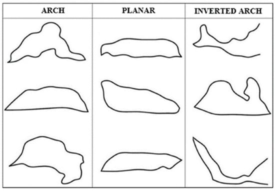
Figure 2.
Type sections of the three classes of the ceiling shape variable according to [22].
(iv) Ceiling thickness (CT), a geotechnical parameter representing the cave’s depth between the ground surface and the ceiling. The values assigned to this parameter can be classified according to Table 3.

Table 3.
Ceiling thickness from CGI according to [22].
Each of the mentioned variables generates different results in the CGI classification. The formula used is the following:
where: αRMR = weight assigned to the rock mass rating, βHR = weight assigned to the hydraulic radius, γCS = weight assigned to the ceiling shape, δCT = weight assigned to the ceiling thickness.
The sum of the four weights results in a maximum weight of 100, which represents the best scenario that has low susceptibility to structural instability. Additionally, a value of zero represents the worst-case scenario: the cave is structurally unstable. An extensive bibliography for calculating the weight values used in the CGI classification can be consulted in [22].
Numerical modeling: some of the caves have been modeled using a numerical approach based on the difference finite method [4,25]. The aim of these models was to obtain a safety factor (SF) that can be used to check the degree of stability obtained through the rock mass classifications and empirical approaches. The input parameters for the numerical model were obtained from the geomechanical stations (in different sections of each cave). In order to elaborate on the model, the input data must incorporate (a) the geometry of the cave, (b) the in situ stress, and (c) a strength criterion. The geometry was obtained with topographic techniques while the stress state was determined by the depth of the cave and the density of the rock (laboratory). The strength criterion used is the Hoek–Brown [4,25], obtaining the parameters from the field observations (GSI, uniaxial compressive strength, UCS, from Schmidt hammer rebound).
3. Results
The Mirador, Gallardo, and Galla-Zoila caves have been analyzed through three empirical and geomechanical classification methods (RMR, Q index, and CGI). The geomechanical characteristics required for the Q index analysis show that the RQD values obtained vary from 50–80 for the Mirador or Kubler cave, 75–100 for the Gallardo cave, and 50–100 in the Galla-Zoila cave (Table 4). The Q index presents values between 0.83–3.00 for the Mirador cave, 0.68–7.33 for the Gallardo cave, and 0.83–17 for the Galla-Zoila cave. The RMR values for the Mirador cave are between 57 and 67, for the Gallardo cave between 44 and 61, and for the Galla-Zoila cave between 41 and 69 (Table 5). The values of the sub-parameters of the CGI method are presented in Table 6. It is important to indicate that “unsupported span” is the measured span of the cave, using existing references of the dimensions or in some cases measuring them with a laser meter. “Unsupported” indicates that the cave has no reinforcements.

Table 4.
Geomechanical characteristic parameters of the Q index and dimensions of lava tubes studies in the Galapagos Islands, Ecuador.

Table 5.
Geomechanical characteristic parameters of the RMR and dimensions of lava tube studies in the Galapagos Islands, Ecuador. For more information regarding the general RMRb and each RMRi rating, see references [15,16].

Table 6.
Geomechanical characteristic parameters of the CGI and dimensions of lava tube studies in the Galapagos Islands, Ecuador.
Subsequently, a comparative analysis was carried out between the Q index, RMR, and CGI values versus the unsupported span (width of the cave). Unsupported span is the span measured of the cave, using existing references of the dimensions, or in some cases measuring them with a laser meter, and it shows that the cave has no reinforcements [1].
Figure 3 shows the caves that classify as stable, transition, and unstable according to the results obtained in the Q index [1]. Hence, most of the stations classify as stable. Figure 3 shows caves seen or visually defined as unstable (filled circles), but they are clearly in the stable zone on the graph. This is worrying because the stable sector of the graph (Figure 3) must show cave stable situations. An unstable cave located in the stable sector is not a good and safe prediction (a more detailed study of those cases should be accomplished). Therefore, the methodology and scores considered in similar cavities must be carefully reviewed. Figure 4 is inconclusive since the RMR is a linear index, not a logarithmic index like Q showing all the caves in a limited range or spectrum. Figure 5 is inconclusive since it shows high CGI indices, greater than 60 with unstable caves, and, conversely, low indices at around 35 with stable caves.
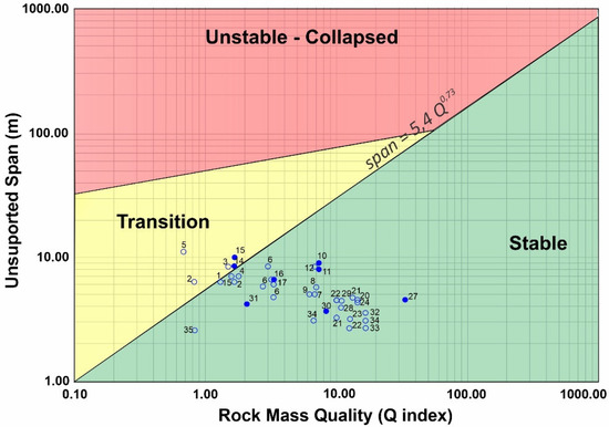
Figure 3.
Q index vs. unsupported charts span: lava tunnel stability analysis. The unfilled circles represent a stable cave and the blue-filled circles represent an unstable cave [1].
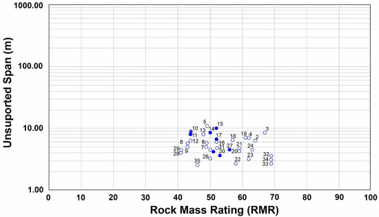
Figure 4.
RMR vs. unsupported analysis span from lava tunnels. The unfilled circles represent a stable cave and the blue-filled circles represent an unstable cave.
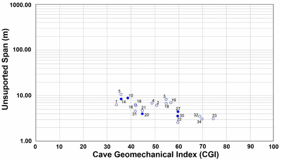
Figure 5.
CGI analysis vs. unsupported span of lava tunnels. The unfilled circles represent a stable cave and the blue-filled circles represent an unstable cave.
A numerical analysis was performed using boundary elements with the Examine2D program [25]. This study was applied to some sectors of each cave (Table 7), and the results are shown in Figure 6. This numerical analysis corroborates the state of the caves. Figure 6 indicates the empirical stability analysis, while Figure 7 adds the factor of safety (FS). The results of the safety factors obtained are summarized in Table 8 with the characteristics of the analyzed caves.

Table 7.
Input parameters used in the Examine2D program.
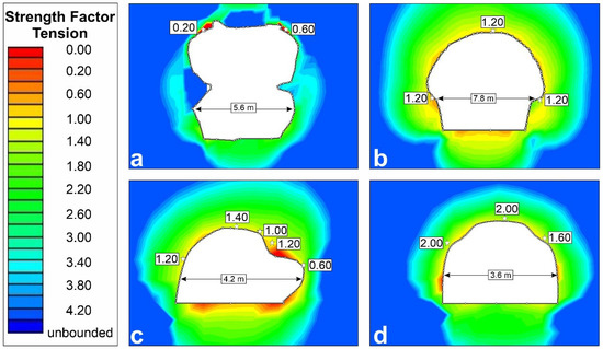
Figure 6.
Analyses in Examine2D: (a) Mirador cave GS-M-02; (b) Gallardo cave GS-G-06; (c) Galla-Zoila cave GS-GZ-12; and (d) Galla-Zoila cave GS-GZ-13.
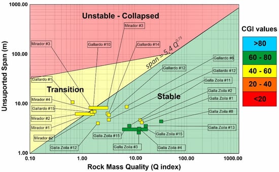
Figure 7.
Comparison between values of CGI, Q index, and stability of the caves.

Table 8.
Comparison of cave stability analysis methods.
Four caves were considered for the analysis: Mirador GS-M-02, Gallardo GS-G-06, Galla-Zoila GS-GZ-12, and Galla-Zoila GS-GZ-13. The results indicated that the Galla-Zoila cave GS-GZ-13, located in the stable zone according to Figure 7, has a safety factor of 2. However, as the caves approach the transition zone, the safety factor decreases, as is the case of Gallardo GS-G-06 (safety factor between 1.2), Galla-Zoila GS-GZ-12 (safety factor between 0.2 and 1.2), and Mirador GS-M-02 (safety factor between 0.2 and 0.6).
Furthermore, we should differentiate between the safety factor and the “collapse” of the cave, and between safety factors and the detachment of some slabs. If we look at images a and c in Figure 6, we see that the cave has FS above 1 (green colors). Nevertheless, there are specific points where there may be minor stress effects and flakes that come off. This effect does not compromise the overall stability of the lava tube but rather shows that there may be small, localized instabilities that need to be monitored. Figure 6b,d have factors of safety above 1 in all sectors of the cave, which indicates that no slab falling is expected. Blue and green colors in Figure 6 indicate high FS, while yellow values represent FS just above 1. Orange and red colors indicate instability (FS < 1). The safety factors obtained are superimposed in Figure 8. The more centered caves in the stable zone have higher safety factors than those located in the zones close to the transition.
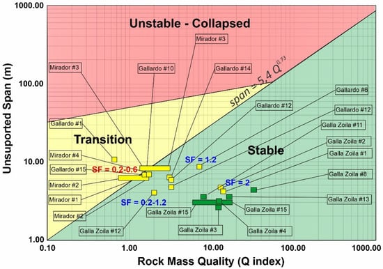
Figure 8.
Safety factors in the analyzed caves.
4. Discussion
The results from the stability analysis based on the Q index, CGI, numerical modeling, and visual inspection are synthesized in Table 8. The analysis based on the Q index shows greater similarity with the visual description of the stability of the caves.
Figure 7 synthesizes the results with the two geomechanical methodologies: the Q index and the CGI on the general image for caves of all kinds, karstic and volcanic [1]. We expect that the Q index and CGI coincide, as we see from some caves. For example, CGI values are in green (60–80) within the green, stable area of the graph, and caves are in yellow-orange (CGI 60–20) in the transition zones of the graph (yellow in Figure Q-span). What poses problems and results on the side of insecurity is finding dangerous caves that are predicted to be unstable and fall in the green–stable zone of the Q-span graph.
Furthermore, in Figure 8, the values of the factor of safety of the four numerical models carried out appear overprinted in the Q-span graph: increasing safety factors appear towards the lower right corner (which is expected). This implies a greater stability in both approaches. An FS or SF less than 1 appears in the transition zone, two FS of 1.2 are parallel to the boundary line, and one FS value of 2 is far from it. These analyzed points suggest that safety factor isolines could be drawn, as in [4]. Future research should perform many more calculations to map these zones and enrich the database.
The Q index is faster to obtain than the CGI method but requires the auxiliary graph (Figure 3). The CGI method indicates the stability just by the value of the index. Figure 7 shows a good correlation between the Q index and its chart with the recommendations of the CGI (yellow and green colors, meaning medium and good quality). Figure 8 shows what is expected: caves located in the transition zone should have lower FS values than those located in the stable zone.
5. Conclusions
The methodologies used exhibited different points of view for the stability analysis of lava tubes. The comparison graphs of the methods showed similarities concerning the visual description. However, the stability method based on the Q index was the closest to the description made in the field.
The values obtained from the CGI were less conservative than those obtained through the Q index, visual inspection, and those made via numerical methods. In addition, in some of the caves the input parameters required for analysis via this method were not obtained.

Table 9.
Acronyms used in the text.
Table 9.
Acronyms used in the text.
| RMR | Rock Mass Rating |
|---|---|
| Q | Q index |
| CGI | Cave Geomechanical Index |
| CS | Ceiling shape |
| CT | Ceiling thickness |
| Weight assigned to the rock mass rating for the CGI classification | |
| Weight assigned to the hydraulic radius for the CGI classification | |
| Weight assigned to the ceiling shape for the CGI classification | |
| Weight assigned to the ceiling thickness for the CGI classification | |
| Jn | Joint set number |
| Jr | Joint roughness number |
| Ja | Joint alteration number |
| Jw | Joint water reduction |
| SRF | Stress reduction factor |
| RMR1 | Strength of intact rock material (rating assigned for the RMR) |
| RMR2 | Rock quality designation (rating assigned for the RMR) |
| RMR3 | Spacing of discontinuities (rating assigned for the RMR) |
| RMR4 | Condition of discontinuities (rating assigned for the RMR) |
| RMR5 | Groundwater condition (rating assigned for the RMR) |
| RMRb | Basic RMR |
| RMRi | RMR of geomechanical station i |
| EG# | Geomechanical station number # |
| Em | Rock elastic modulus, Young modulus |
| GSI | Geological Strength Index |
| mi | Parameter used in Hoek–Brown failure criterion |
| F.S | Factor of safety |
| D | Disturbance factor used in Hoek–Brown criterion |
| S F | Safety factor (same as FS) |
Author Contributions
Conceptualization, G.B., O.S., M.M., S.L. and L.J.B.; methodology, G.B., O.S. and L.J.B.; software, G.B., O.S. and L.J.B.; validation, G.B., O.S. and L.J.B.; formal analysis, G.B. and O.S.; investigation, G.B., O.S., M.M., S.L. and L.J.B.; writing—original draft preparation, G.B. and O.S.; writing—review and editing, G.B., O.S., M.M., S.L. and L.J.B.; supervision, M.M., S.L. and L.J.B. All authors have read and agreed to the published version of the manuscript.
Funding
This research is part of a master thesis of the Geotechnics Master Program of the Faculty of Engineering in Earth Sciences (FICT, acronym in Spanish) of ESPOL Polytechnic University in Guayaquil, Ecuador.
Acknowledgments
The authors gratefully acknowledge the support of the Dean of Research at ESPOL Polytechnic University. We are grateful to the editor and the two anonymous referees for the detailed reviews that helped us improve the manuscript.
Conflicts of Interest
The authors declare no conflict of interest.
References
- Jordà-Bordehore, L. Stability Assessment of Natural Caves Using Empirical Approaches and Rock Mass Classifications. Rock Mech. Rock Eng. 2017, 50, 2143–2154. [Google Scholar] [CrossRef]
- Grenier, C. Conservation against nature. The Galapagos Islands. In Conservation against Nature. The Galapagos Islands; Abya Yala: Quito, Ecuador, 2007. [Google Scholar] [CrossRef]
- Addison, A. Galapagos—Caving the Equator. Natl. Speleol. Soc. News 2011, 69, 8–17. [Google Scholar]
- Jordà-Bordehore, L.; Toulkeridis, T. Stability assessment of volcanic natural caves—Lava tunnels—Using both empirical and numerical approach, case studies of Galapagos Islands (Ecuador) and Lanzarote Island (Canary—Spain). In Proceedings of the ISRM International Symposium—EUROCK, Ürgüp, Turkey, 29–31 August 2016; pp. 835–839. [Google Scholar] [CrossRef]
- Geist, D.; Diefenbach, B.A.; Fornari, D.J.; Kurz, M.D.; Harpp, K.; Blusztajn, J. Construction of the Galápagos platform by large submarine volcanic terraces. Geochem. Geophys. Geosyst. 2008, 9, 1–27. [Google Scholar]
- Vallejo, S. Distribution of Late-Holocene Volcanic Ash on the Coast of Ecuador. Ph.D. Thesis, 2011. [Google Scholar]
- Sauro, F.; Pozzobon, R.; Massironi, M.; De Berardinis, P.; Santagata, T.; De Waele, J. Lava tubes on Earth, Moon and Mars: A review on their size and morphology revealed by comparative planetology. Earth-Sci. Rev. 2020, 209, 103288. [Google Scholar]
- Jordà-Bordehore, L.; García, R.; Alonso-Zarza, A.; Romero, C. Stability assessment of shallow limestone caves through an empirical approach: Application of the stability graph method to the Castañar Cave study site (Spain). Bull. Eng. Geol. Environ. 2016, 75, 1469–1483. [Google Scholar]
- Calvari, S.; Pinkerton, H. Lava tube morphology on Etna and evidence for lava flow emplacement mechanisms. J. Volcanol. Geotherm. Res. 1999, 90, 263–280. [Google Scholar]
- Mulas, M.; Cioni, R.; Andronico, D.; Mundula, F. The explosive activity of the 1669 Monti Rossi eruption at Mt. Etna (Italy). J. Volcanol. Geotherm. Res. 2016, 328, 115–133. [Google Scholar]
- Waltham, A.C.; Park, H.D. Roads over lava tubes in Cheju Island, South Korea. Eng. Geol. 2002, 66, 53–64. [Google Scholar]
- Jordá-Bordehore, L.; Toulkeridis, T.; Romero-Crespo, P.L.; Jordá-Bordehore, R.; García- Garizabal, I. Stability assessment of volcanic lava tubes in the Galápagos using engineering rock mass classifications and an empirical approach. Int. J. Rock Mech. Min. Sci. 2016, 89, 55–67. [Google Scholar] [CrossRef]
- Barton, N.; Grimstad, E. The Q System following thirty years of development and application in tunneling projects. In Proceedings of the ISRM Regional Symposium EUROCK 2004 & 53rd Geomechanics Colloquy, Salzburg, Austria, 7–9 October 2004; Schubert, W., Ed.; Verlag Glückauf: Essen, Germany, 2004. [Google Scholar]
- Barton, N.; Grimstad, E. Q-System—An Illustrated Guide following Forty Years in Tunneling. 2014. Available online: www.nickbarton.com (accessed on 20 May 2022).
- Bieniawski, Z.T. Engineering Rock Mass Classification; John Wiley & Sons: Hoboken, NJ, USA, 1989. [Google Scholar] [CrossRef]
- Bieniawski, Z. Errors in the Application of Geomechanical Classifications and Their Correction; Ingeopres: Madrid, Spain, 2011; Volume 208, pp. 10–21. [Google Scholar]
- Barton, N.; Bieniawski, Z. RMR and Q-setting records straight. Tunn. Tunn. Int. 2008, 2, 26–29. [Google Scholar]
- Grimstad, E.; Barton, N. Updating of the Q-System fr NTM. In Proceedings of the International Symposium on Sprayed Concrete-Moderns Use of Wet Mix Sprayed Concrete for Underground Support, Fagernes, Norway, 22–26 October 1993; Kompen, C., Opshal, S.L., Berg, S.L., Eds.; Norwegian Concrete Association: Oslo, Norway, 1993. [Google Scholar]
- Hoek, E. Practical Rock Engineering. Set of Course Notes. Shear Strength of Discontinuities. 2014. Available online: www.rocscience.com/education/hoeks_corner (accessed on 20 May 2022).
- Romana-Ruiz, M. Excavation and Support Recommendations for Tunnels; Jornadas Hispano-Lusas sobre Obras Subterráneas: Madrid, Spain, 2003; pp. 105–120. [Google Scholar]
- Bieniawski, Z. Engineering Classification of jointed rock masses. Civ. Eng. S. Afr. 1973, 15, 333–343. [Google Scholar]
- Brandi, I.V.; Barbosa, M.R.; Barata, A.; de Paula, R.G.; Correa, T.; Mota, H.; Lima, D.; Osborne, R.A.; Vale, S.A.; Lima, N.; et al. Cave Geomechanical Index (CGI). Classification and Contribution to the Conservation of Natural Caves in the Iron Mines. Geoconserv. Res. 2021, 3, 134–161. [Google Scholar] [CrossRef]
- Bieniawski, Z. The geomechanics classification in rock engineering applications. In Proceedings of the 4th Congress of the International Society for Rock Mechanics, Montreux, Switzerland, 2–8 September 1979; OnePetro: Richardson, TX, USA, 1979. [Google Scholar]
- Milne, D.M. Underground Design and Deformation Based on Surface Geometry. Master’s Thesis, University of British Columbia, Vancouver, BC, Canada, 1997. [Google Scholar]
- Laubscher, D.H. Geomechanics classification of jointed rock masses: Mining applications. Inst. Min. Metall. Trans. Sect. 1977, 86, 1–8. [Google Scholar]
Publisher’s Note: MDPI stays neutral with regard to jurisdictional claims in published maps and institutional affiliations. |
© 2022 by the authors. Licensee MDPI, Basel, Switzerland. This article is an open access article distributed under the terms and conditions of the Creative Commons Attribution (CC BY) license (https://creativecommons.org/licenses/by/4.0/).