Article

A Segmentation Approach to Identify Underwater Dunes from Digital Bathymetric Models

Département des Sciences Géomatiques, Université Laval, Québec City, QC G1V 0A6, Canada
*
Author to whom correspondence should be addressed.
Geosciences 2021, 11(9), 361; https://doi.org/10.3390/geosciences11090361
Submission received: 23 June 2021 / Revised: 9 August 2021 / Accepted: 11 August 2021 / Published: 25 August 2021

Abstract

:
The recognition of underwater dunes has a central role to ensure safe navigation. Indeed, the presence of these dynamic landforms on the seafloor represents a hazard for navigation, especially in navigation channels, and should be at least highlighted to avoid collision with vessels. This paper proposes a novel method dedicated to the segmentation of these landforms in the fluvio-marine context. Its originality relies on the use of a conceptual model in which dunes are characterized by three salient features, namely the crest line, the stoss trough, and the lee trough. The proposed segmentation implements the conceptual model by considering the DBM (digital bathymetric model) as the seafloor surface from which the dunes shall be segmented. A geomorphometric analysis of the seabed is conducted to identify the salient features of the dunes. It is followed by an OBIA (object-based image analysis) approach aiming to eliminate the pixel-based analysis of the seabed surface, forming objects to better describe the dunes present in the seafloor. To validate the segmentation method, more than 850 dunes were segmented in the fluvio-marine context of the Northern Traverse of the Saint-Lawrence river. A performance rate of nearly 92% of well segmented dunes (i.e., true positive) was achieved.

1. Introduction

Bathymetric data acquired by multibeam echosounder systems (MBES) can be used for multiple applications, the primary purpose being to produce nautical charts. These datasets with high-resolution and accuracy can be used to study the sea bottom morphology, to inspect underwater engineering structures, and for the maintenance in navigation channels by dredging operations [1]. In this context, the recognition of the underwater sedimentary structures and their dynamics from a DBM (digital bathymetric model) is crucial to ensure safe navigation. Specifically, underwater dunes are large and mobile structures on the sea bottom. They represent a danger for navigation safety since shipping routes necessarily cross dune fields and sand banks, especially nearshore to access harbours and in navigation channels [2].
Underwater dune identification and segmentation from a DBM is still a manual process. As mentioned in [2], this task has many disadvantages, such as being time consuming, subjective, inaccurate, tedious, and less suited to handling large data flow. Indeed, underwater dunes, as many landforms, are fuzzy objects, and their perception may vary from different users depending on their background or experience. Few methods have been proposed to segment underwater dunes from a DBM. In [3], the authors proposed a method consisting of two steps. The first carries out the calculation of the terrain parameters. These parameters are calculated by the geomorphons method proposed in [4]. The second step is the identification of the underwater dunes themselves and their characterization. In this second step, different geomorphon classes are aggregated in order to form the dune entity after a few processing operations. The authors proposed in [1] the segmentation of the underwater dunes through geodesic morphometry. This work addresses the segmentation of the dunes from a bathymetric TIN (triangulated irregular network) surface. This method extracts the salient features of the dunes, such as crest and valley lines. To deal with the presence of ripples, a significant difficulty when segmenting dunes, this work proposed an anisotropic filter to preserve the underwater dunes and eliminate the ripples. The authors of [2] also proposed a method to segment and classify underwater dunes from the sea bottom surface. This work considers triangular meshes instead of a DBM regular grid. Differential geometry is used to identify crest lines. These are then used as seed regions to segment the underwater dunes. In [5], the authors proposed the BRESS method, which considers multiple inputs (DBM from MBES survey and backscatter mosaic) as well as the implementation of segmentation methods. In this method, the seafloor is initially segmented using geomorphons (therein called bathymorphons). Then the initial segments of the DBM are analyzed with their respective backscatter intensity to generate the final segments by merging or splitting the previous segments.
Almost all of these previous works consider underwater dunes in marine environments and not in fluvio-marine environments. Such environments are highly dynamic where dunes are organized in different patterns. Dunes are not isolated and well defined but form fields of underwater dunes, where these sedimentary structures are adjacent to or superimposed on each other. Furthermore, such places are often important navigation channels, requiring frequent dredging operations to ensure navigation safety. As a result, surveyed dunes can be incomplete. Thus, methods proposed in the previous studies are inadequate for dune mapping in the fluvio-marine context. In this paper, we propose that a new solution for segmenting the dunes adapted to fluvio-marine environments is required. To meet this goal, we propose a cognitive approach in which the underwater dune object is defined through a conceptual model. The aim is to eliminate the subjectivity of dune identification according to the data acquisition scale and the lack of a formal dune definition.
The proposed model is applied to the Northern Traverse, a navigation channel in the Saint-Lawrence River (Québec, Canada). Most methods proposed in the literature considered the sea bottom modeled by a TIN. The raw datasets consisting of soundings recorded by the MBES were gridded as a surface and then exported as point clouds with a specific density of 1 point/m2. Only the regular point clouds were available. These datasets were acquired in the context of the channel navigation maintenance (dredging). Backscatter information was not available.
This paper is organized in four sections. The first section proposes a state-of-the-art geomorphometry analysis and OBIA (object-based image analysis). The second section is dedicated to the definition of underwater dunes as sedimentary structures on the seabed surface. This definition, based on the literature, aims to introduce the salient features used in the proposed segmentation method. The third section presents the dune segmentation method itself. In this section, the dune landform is formalized through a conceptual model, and the operational model that implements it to segment the dune from a DBM is described. The fourth section provides the results and performances provided by the proposed segmentation method considering different sectors of the Northern Traverse study site in the Saint-Lawrence river. The last section presents the conclusions and the prospects for future research addressing the segmentation of underwater dunes from DBM.

2. Advanced Geomorphometry Analysis

The segmentation of underwater landforms from the seabed can be conducted using different methods given the context of the analysis and the data itself. In the marine context, as mentioned in [6], object features can be segmented from the seabed using pixel-based analysis. However, object-oriented methods such as object-based image analysis (OBIA) have become increasingly popular in marine studies to segment and classify landforms. Indeed, these methods generally associate geomorphometric analysis and OBIA approaches. These methods rely on the landform definition, which can be expressed as landform ontologies. In this section, we aim to review the different methods that can be employed to segment landforms from a sea bottom surface.

2.1. Geomorphometry

Landforms can be defined as geomorphometric objects. These objects generally have a third dimension (volumetric) and can be identified and segmented from a DEM (digital elevation model). The identification of landforms is intimately related to the resolution of the DEM and the analysis scale as well as the definition of the landform itself. The geomorphometry can be defined as the science of the quantitative characterization and analysis of the surfaces. It can be divided into general and specific geomorphometry. The first represents the calculation of terrain attributes, such as slope, orientation, curvature, and terrain variability. It generally uses neighborhood analysis in the DBM context. The latter focuses on the calculation of terrain features or objects and is relatively rare in the marine environment. Specific geomorphometry generally relies on the combined properties of several terrain attributes [7,8]. In the bathymetric context, both general and specific geomorphometry are crucial in the interpretation, description, and classification of the sea bottom geomorphology.
The geomorphometric analysis proposed in [8] is based on differential geometry principles. This method calculates the geomorphometric parameters of a DEM from features extracted using quadratic approximation on a local window. Extracted features are peak, ridge, pass, plane, channel, and pit. The authors of [9] proposed an OBIA approach to classify landform elements based on a geomorphometric analysis. In this method, the modeled surface is segmented considering a multi-scale approach. Regions are delineated considering areas with homogenous slope gradient and slope curvature characteristics. Geometric calculations are based on geomorphometric descriptors of the DEM, such as elevation, profile curvature, plan curvature, and slope gradient. Therefore, the surface can be classified using a structured hierarchy that groups the different geomorphometric classes into similar region classes. The resulting regions are classified into nine different landform element classes (i.e., peak, shoulder, steep slope, flat or gentle slope, side slope, nose slope, head slope, negative contact, and toe slope) considering fuzzy logic rules.
In the underwater context, the authors of [1] proposed a method for underwater dune segmentation through geodesic morphometry using a TIN representing the seafloor. This method calculates the curvature of the surface in the differential scale space to identify the crest lines defining the dunes. The authors of [2] also used differential geometry in order to extract the geomorphometry from a triangular mesh representing the seafloor. In fact, to extract the crestlines of the dunes from the modeled seabed, this work considered the estimation of the principal curvatures based on a local fitting approximation.
When conducting the analysis of a regular gridded DBM, the method developed in [4], introducing the concept of geomorphologic phenotypes (geomorphons), can be of interest for landform segmentation. This method is based on pattern recognition principles instead of differential geometry. As highlighted in [3], geomorphons do not involve the derivation of the surface parameters. This method also eliminates the use of a fixed window for the terrain analysis, using an 8-neighborhood adapted to the terrain topography. The method describes the terrain based on the morphological terrain types including standard elements of landscape, such as ridge, peak, valley, pit, slope, etc. The identification of such standard elements of landscape can be used to identify the landforms primitives, in a cognitive approach. Indeed, this is the method used in [3] to segment the underwater dunes from DBM. Geomorphons have also been used in the seafloor segmentation method proposed in [5]. In this work, the ten possible geomorphon (bathymorphon) classes were grouped into six possible “geoform” classes in order to simplify the classes proposed in [3]. Each class represents a “bathymorphologic” element of the seafloor (e.g., flat, ridge, shoulder, slope, footslope, and valley).

2.2. OBIA

Pixel-based analysis of an image may be used as long as the pixel size remains coarser or similar in size to the objects of interest. However, when objects of interest are made up of several image pixels, object-based analysis is preferred. Objects of interest can be defined as discrete regions of an image that are internally coherent (i.e., pixels are homogeneous according to a predefined criteria) and different from their surroundings (i.e., the pixels inside the region are different from the pixels outside the region according to the predefined criteria). A distinction has to be made between the primitives of the objects of interest and the objects of interest themselves. The latter are objects matching real-world objects, such as landforms. The former are usually components of the objects of interest. Compared to single pixels, objects of interest are characterized by their shape that can be described by geometric measures, such as their size, length, etc. Topological relations can also be defined for objects of interest as well as for thematic classification [10,11,12].
Usually, an OBIA approach involves two steps: segmentation and classification. The results of the segmentation are regions, namely groups of connected pixels extracted according to a homogeneity criterion. These regions are either object candidates or primitives of object candidates. They need to be further processed in order to be considered as meaningful objects or primitives. Mathematical morphology operations, such as opening and closing, can be used in order to better delineate the boundary of the objects or their primitives [13,14]. Once the segmentation is completed, the segmented regions can be aggregated to generate the objects [9,15]. This aggregation can be done by neighbourhood operations since regions belonging to the same object should be close to each other. Then, the classification step of the OBIA considers the shape of the aggregated regions and geomorphometric descriptors of the pixels composing the objects to define different classes and classify the segmented objects.
The authors of [16] applied an OBIA approach to the DBM to segment geomorphic features on the sea bottom in the context of the classification of submarine canyons. The work involves different types of sonar data (MBES and sidescan sonar data) and their derivatives (e.g., slope, plan curvature, slope curvature, rugosity, etc.). The marine landscape mapping is divided into two steps. The first step consists of terrain analysis using data resampling and an automated procedure for multiple scale analysis. In fact, this multiple scale analysis incorporates the terrain indices produced at different scales to optimise the detection of details and features for the characterisation of the seabed. The authors used the estimation scale parameter (ESP) proposed in [17] to estimate the scale parameters. The second step addresses the actual landscape classification. This step consists of a multivariate statistical analysis carried out considering the different types of data and derivatives. Given the large number of input data, principal component analysis (PCA) is applied to select the most significant features. Then, K-means clustering is carried out in order to generate six marine landscapes (e.g., channel floor, flanks, wall, or cliff) that represent the geomorphological features present in submarine canyons. The number K of clusters is determined through an optimization process.
The authors of [18] proposed an OBIA method for mapping cold-water coral carbonate mounds. It consists of the classical OBIA steps, namely segmentation and classification of the DBM. The segmentation is conducted according to a multi-resolution approach. More specifically, different segmentations are carried out at given resolutions. Finer resolutions provide smaller regions, while coarser resolutions provide larger regions. The classification is based on user-specified combinations of the region features (e.g., shape, extent, maximum pixel value, object mean value).
As previously mentioned, in [5], the authors proposed a method to segment the seafloor using a multiple input analysis with the bathymetry from the MBES and the backscatter mosaic. In this method, the seafloor DBM is initially segmented into six “geoform” elements. The resulting regions are area kernels (connected regions of common bathymorphon classes). Then, the method evaluates “each area kernel within the context of the backscatter mosaic much as an experienced analyst would use the backscatter to understand the context of given morphological regions”. The seafloor final segments are homogeneous and non-overlapping with specifically associated attributes that can be used for the seafloor analysis. The BRESS proposed in [5] was used in [19] to segment the seafloor in the marine landscape.
An OBIA approach was also used in [3] towards the segmentation of underwater dunes from a DBM. In this work, the segmentation relies on the geomorphometric analysis of the DBM using the geomorphons algorithm [4] as previously mentioned. In their proposed method, the pixels classified by the geomorphon, such as summit, ridge, spur, and slope, are associated with the dune landform. Indeed, all these geomorphons characterize the elements of the dunes that are further discussed in the paper. Then, these pixels are reclassified into a dune class and the remaining pixels are set to null. The dunes are further processed and can be analyzed based on the calculation of their features.
Many OBIA approaches results in classified regions rather than landform objects. Indeed, the resulting primitives provided by the segmentation of the surface are generally landform elements rather than the landform itself. These primitives need to be further analyzed and then aggregated to build up the landforms. In the context of the Northern Traverse in the Saint-Lawrence river, this aggregation may not work, since the underwater dunes are adjacent rather than large, isolated dunes. The aggregation may result in a region with the presence of the dunes (field of dunes) instead of the dune objects. Since landforms are fuzzy objects, their perception and understanding are related to human cognition. Therefore, the description of a landform may vary from one user to another, and different geographical contexts can be defined in different ways [20,21]. As a result, an ontological structure describing the landforms and their components is necessary before developing the segmentation approaches. In other words, the ontology will provide the segmentation with a description of the regions to look for on the surface and the approach with a way to aggregate the relevant regions. In [22], an example of such an ontology is proposed. The authors provide a framework to represent landforms defined by their salient features. Hence, the problem of landform identification and segmentation from a surface is to formalize their saliences using terms that can be later translated into an implementation [23]. The next sections present the definition of the underwater dune on the seafloor. Then, a conceptual model formalizes this definition, and an operational model allows the implementation of the segmentation approach.

3. Description of the Underwater Dunes

Before addressing the segmentation of underwater dunes from a DBM, it is important to better understand these complex sedimentary structures. The process of dune formation in the seabed can be described as follows (adapted from [24]): the presence of an irregularity on the sea-bottom affects the current causing a perturbation in the sediment repository. This perturbation creates zones of erosion–deposition and consequently creates other irregularities on the seabed. These initial irregularities are ripples, and the growth of the dunes is the consequence of the accumulation of sediments in these irregularities. Indeed, dune morphology is similar to ripple morphology.
An underwater dune is built up progressively through time by the accumulation of sediments brought by the flow on the seafloor, forming an elongated eminence. This accumulation generates a gentle slope facing the current, the stoss side of the dune, culminating at the crest of the dune. Passing from this line, sediments fall on the lee side of the dune, which is characterized by a steeper slope. Hence, the dune extension is delimited by the bottom of its sides, which corresponds to zones with a change in sediment accumulation. This transition zone is referred to as the trough or the footslope. Since a dune is characterized by two slopes, it is bounded by two troughs. The sedimentary structure begins with a trough and a stoss side leading up to a crest line and follows with sediment avalanches down to the lee side in the direction of the trough [25,26]. The authors of [27] corroborate that a “sand dune is characterized by a more or less linear crest and two sides, a gentle one (stoss side) and a steep one (lee side), limited by a footslope and inner sedimentary discordance”. Henceforward, we shall consider the term “trough” as the boundary of the dune. Figure 1 illustrates a representation of this sedimentary structure.
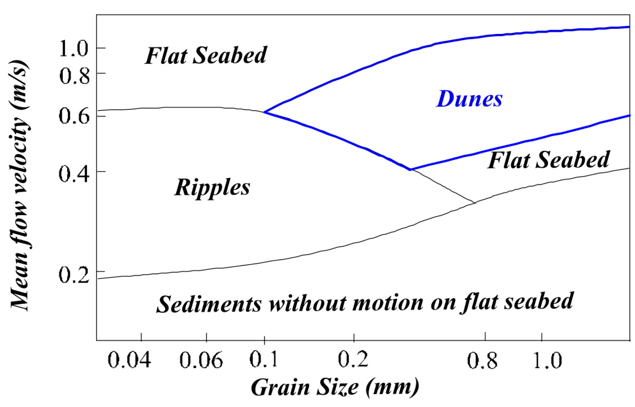
The migration of dunes on the sea-bottom and their shape are correlated to their nature and to hydrodynamic factors. Dunes are related to relatively strong or large-scale sustained flows. They can be found in shallow marine environments, estuaries, deltas, and river channels [25,27,28]. The correlation between the grain size, the velocity of the flow, and the sedimentary structure formed on the seabed can be observed in Figure 2.
Figure 2 shows that dunes are formed with a grain size ranging from fine sand to gravel (i.e., grain size greater than 0.1 mm up to more than 1.0 mm). Dunes are limited in finer sediments, such as silt or very fine sand. This limitation is related to the increase of sediment suspension in the flow. When the finer sediments are predominant, “the suspended load suppresses turbulence in the flow and flow separation does not occur” [25]. Due to the complex flow dynamics, smaller sedimentary structures, such as ripples, can superimpose on underwater dunes [1,28].
The orientation of the crest lines of the dunes is usually perpendicular to the main direction of the current, although angular variations up to 20° can be observed [26]. As previously mentioned, dunes are larger sedimentary structures than ripples, according to the widely accepted classification of underwater dunes [29]. Dunes have a minimum wavelength of 0.6 m and height of 0.075 m. These measures can reach values greater than 100 m and 5 m for the wavelength and the height, respectively. The classification presented in Table 1 concerns sand structures generated by unidirectional currents, bidirectional currents, and the combination of both, and this classification estimates the dune height with the equation H = 0.0677 L 0.8098 , where L represents the wavelength of the dune.
Usually, the height and wavelength increase with flow velocity [1,30]. Instead of being estimated with the equation previously mentioned, the height of dunes can be measured as the shortest distance between a crest line and a line joining both troughs [31]. Regarding the dune length, the wavelength is usually understood as the distance measured between two consecutive dunes at their crest lines. However, such a definition cannot be applied to isolated dunes. In such a context, the proposed wavelength definition is the horizontal distance between the lee and stoss trough of the same dune [24]. Dunes can also be isolated structures or included in a field of dunes on the sea bottom. Dunes with higher sinuosity and high degree of asymmetry (ratio between stoss and lee sides) are characterized by high migration rates, and more linear dunes have the slowest migration rates [1,26,32].

4. Underwater Dune Segmentation from a DBM

Using OBIA, image processing, and landform ontologies, we designed a method to segment underwater dunes from the sea bottom surface modeled by a DBM. In our approach, the salient features describing a dune, those that can be easily perceived and agreed upon, need to be described. When such salient features are available, a complete spatial description of the dunes is not required. Indeed, they act as a skeleton on which the body of the landform is built. Therefore, our approach is formalized through a conceptual model, which relies on the description of the salient features of the dunes independently from the data. This model is then converted into a data-dependent operational model and implemented. The conceptual and operational model are described in this section.

4.1. Underwater Dunes Conceptual Model

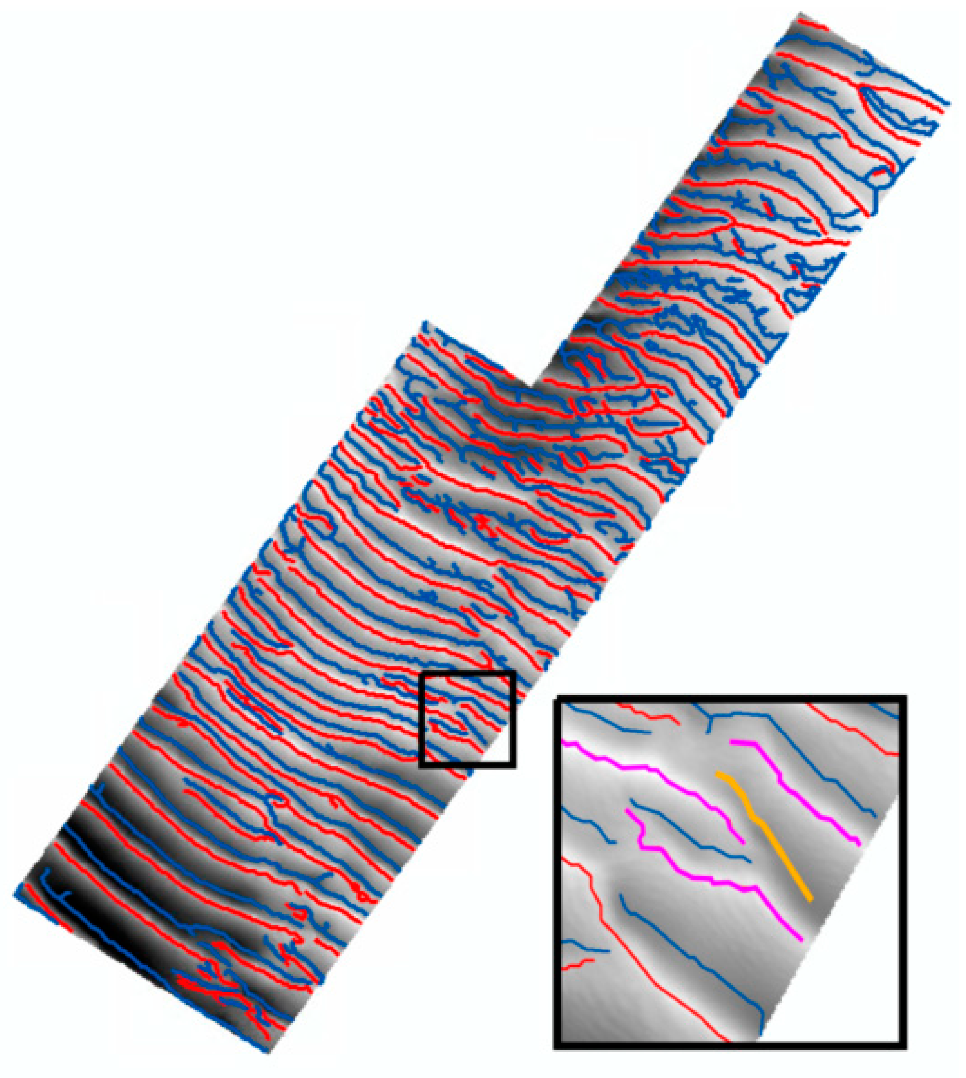
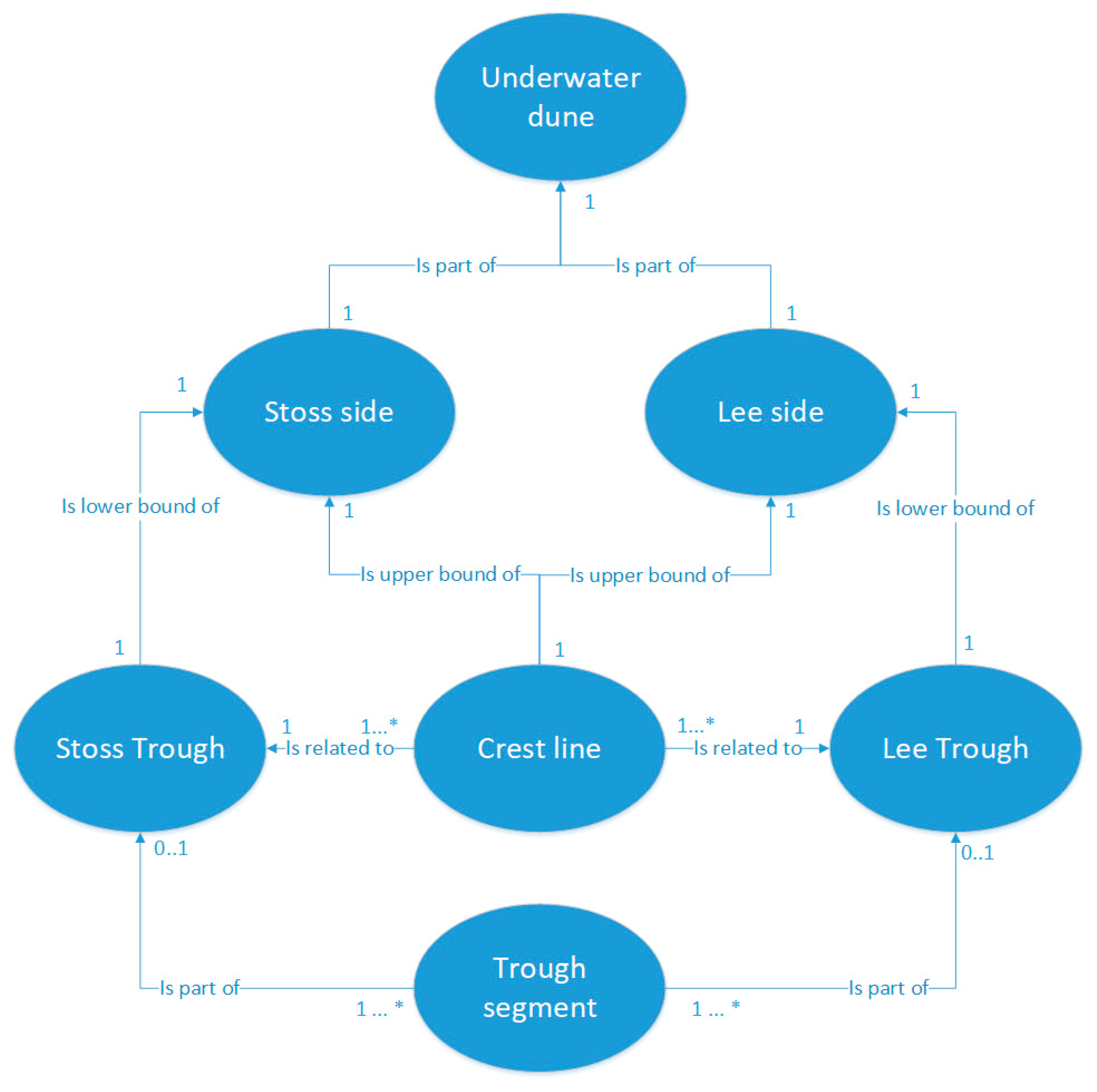
The formalization of the underwater dunes through a conceptual model considers that this landform can be identified on the seabed from three salient features, namely the crest line, the stoss trough, and the lee trough. The crest line is a linear feature located in the higher zone of the dune. This feature is the upper bound of both sloping sides of the landform. The stoss and lee troughs represent the boundary of the dune objects and are also represented as linear features. They bound the stoss and lee sides, respectively. These boundaries are regarded as fuzzy rather than crisp since their position is not marked as clearly as the crest lines. Indeed, they define an area of transition with a change in the sedimentary accumulation. In fact, they represent a transition zone between the dune and the other sea bottom landforms. Even if they are the transition zone that delineates the boundary of the dune object, they are represented as lines. Therefore, the lee and stoss troughs can be completely or partially detected from a DBM, depending on the steepness of the slope associated with the sloping side of the dune. Accordingly, the conceptual model should consider that the troughs delineating the dunes boundaries can be composed of 1 or several trough segments. These trough segments are linear features on the sea bottom. In the conceptual model, the trough segment can be part of one trough or none, since some trough segments can belong to another underwater landform. The crest line is related to one lee and one stoss trough. However, lee and stoss troughs can be related to more than one crest line, since one trough can be part of several consecutive dunes (i.e., in a field of dunes), as illustrated in Figure 3.
In addition to the salient features, the conceptual model considers two components of the dune, namely the lee and stoss sides. These components are the sloping sides bounded by the salient features. That is, the lee side is the surface between the crest line and the lee trough, and the stoss side is the surface between the crest line and the stoss trough. These components link the dune salient features and allow a spatially complete object to be formed. One crest line is related to one lee and one stoss side. The stoss and lee troughs are the lower bound of the stoss and lee sides, respectively. In the case of an isolate dune, the stoss and lee troughs meet at their ends, thus completing the perimeter of the dune. Figure 4 summarizes the underwater dunes conceptual model.

4.2. Operational Model

This section describes the operational model that allows the segmenting of underwater dunes from a DBM, considering the conceptual model described in the previous section. This model consists of two phases. The first phase addresses the salient features identification. As underlined in the conceptual model, these features are the crest line and the lee and stoss troughs as boundaries of the dune object. The second phase is the identification of the dune object itself from the salient features previously identified. The result is an image with segmented dune objects. Although our model seems to have some similarities with the approach proposed in [3] (including the fact that both models are organized in two phases), it is clearly different. Indeed, the proposed method identifies salient dune features (i.e., crest, troughs), while the approach proposed in [3] isolates regions potentially corresponding to dunes. Our method then analyzes the extracted salient features and combines them to form individual dunes. In contrast, the authors of [3] analyze the regions formed in the previous step and retain only those that are consistent with the three-dimensional dune features. As a result, our method extracts discrete objects while [3] extracts groups of adjacent pixels consistent with dune characteristics.

4.2.1. Phase I—Salient Features Identification

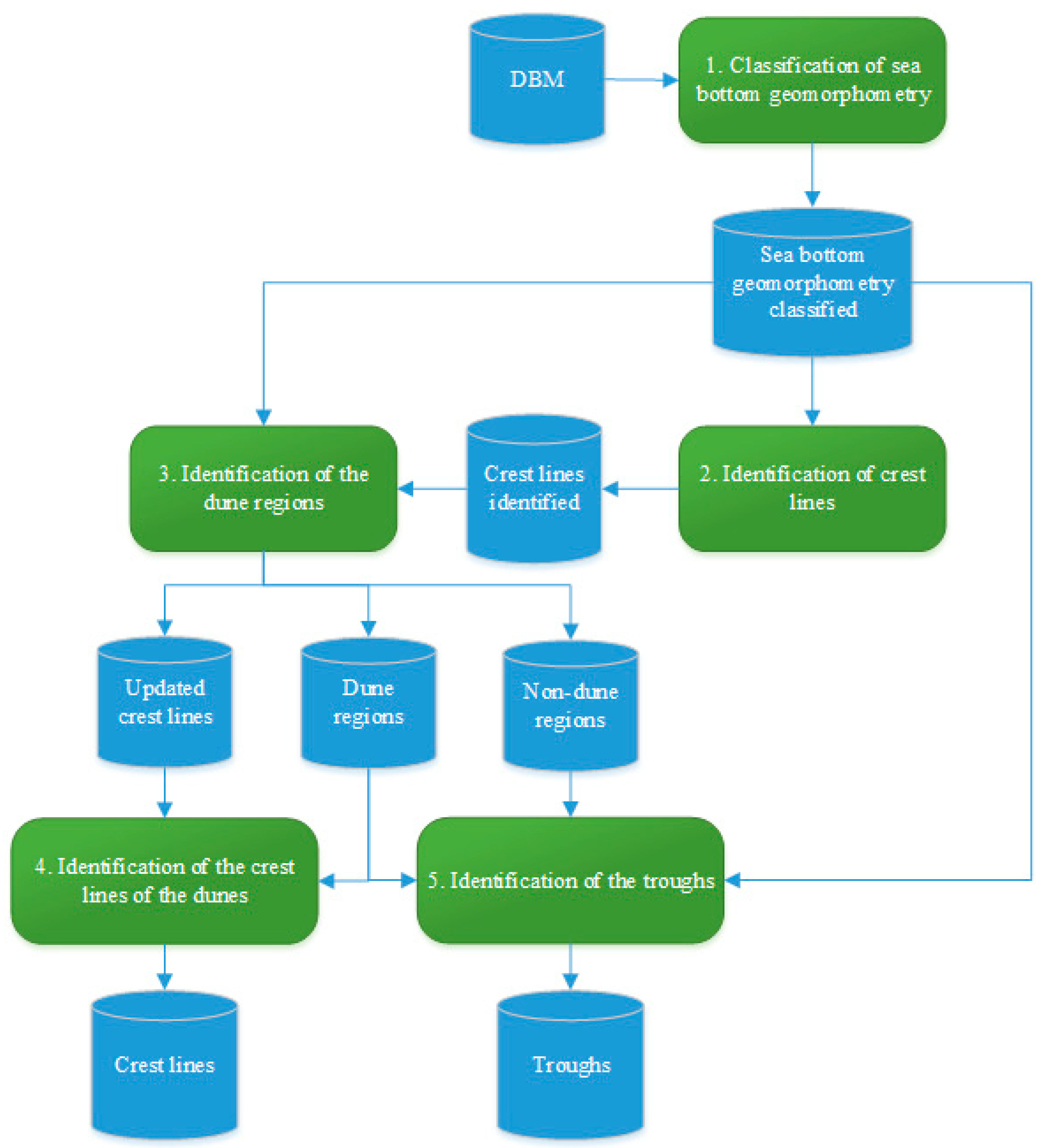
Phase I of the operational model addresses the identification of the sea-bottom salient features from a DBM. This phase consists of the following five processes:
  • Pixel-based classification of the sea bottom geomorphometry;
  • Identification of the crest lines;
  • Identification of the dune and non-dune regions;
  • Improvement of the crest lines of the dune regions;
  • Identification of the troughs.
All these processes are illustrated in Figure 5. Their rationale and contents are described in the following sections.

A. Pixel-Based Classification of Sea Bottom Geomorphometry

The 1st process aims to identify the zones of the DBM that can be associated with underwater dunes in the sea bottom surface. For this purpose, a geomorphometric analysis of the sea bottom was performed. In our approach, this analysis was based on the geomorphons method [4]. As previously mentioned, the geomorphons rely on the concept of geomorphologic phonotypes classification of the DBM. The result of this process is the classified geomorphometry of the DBM (i.e., each pixel has a geomorphometric class). In their approach, the authors of [3] extracted the entire dune landform by grouping and processing pixels classified as summit, ridge, spur, and slope. The dunes of the Northern Traverse of the Saint-Lawrence river cannot be segmented by grouping these different geomorphon classes. In this fluvio-marine context, these sedimentary structures are not isolated dunes well defined on the seabed. Indeed, the studied zone consists of fields of dunes and superimposed structures in a highly dynamic context. Nonetheless, geomorphons are still useful in our approach to identify the salient features composing the underwater dunes.

B. Identification of Crest Lines

Since our approach is based on the salient features of the dunes defined by the proposed conceptual model, the 2nd process aims to identify the crest lines of the DBM. The crest lines of the DBM are represented as line segments located in crest regions. In the proposed operational model, these crest regions correspond to two geomorphons classes, namely summit and crest. As a result, neighboring pixels of the DBM belonging to either one of these two classes are grouped in a region. Then, the regions are filtered according to their extents to preserve only the most reliable and consistent ones with a dune crest. Furthermore, mathematical morphology operations (i.e., opening) are applied to remove non-significant regions. At that stage, the preeminent crest regions are identified. To convert the crest regions (i.e., surfaces) into crest lines (i.e., open contours), skeletonization is applied. The output is a binary image in which the intensity value of crest line pixels is set to 1, while the intensity value of the other pixels is set to 0.

C. Identification of the Dune and Non-Dune Regions

This process aims to identify the dune regions, which circumscribe the crest lines and consequently delineate their boundaries. In our approach, we considered that the boundaries of non-dune regions correspond to the troughs of the dunes when these non-dune regions are adjacent to the dunes. In fact, when two dunes are adjacent, this non-dune region should be linear, defining the trough line, which is the boundary between both dunes. As in the second process, non-dune regions are identified using five geomorphon classes (i.e., footslope, valley, depression, hollow, and flat). Neighboring pixels of the DBM belonging to either one of these five classes are aggregated forming a region. These regions are filtered according to their surface. The output of these steps is a binary image in which the intensity value of non-dune region pixels is set to 0, while the intensity value of the other pixels is set to 1. A binary image representing the dune regions is obtained directly by taking the complement (0 becomes 1 and 1 becomes 0) of the non-dunes binary image. A mathematical morphology operation (i.e., opening) is applied on the binary image of the dune regions in order to remove the non-significant zones. A filtering process is applied to preserve only the crest lines (i.e., cf. step 2) located inside dune regions. The non-dune regions binary image is updated as the image complement of the dune regions binary image. Thus, this process results in three binary images: non-dune regions; dune regions; and updated crest lines.

D. Improvement of the Crest Lines of the Dune Regions

Considering the dunes regions and the crest lines, the 4th process aims to identify and extract the crest lines of the dunes. To achieve this goal, the dune regions are filtered to preserve only the most consistent with the surface area of underwater dunes. Since the crest lines are extracted using a skeletonization process (cf. 2nd process), some artefacts may appear at the ends of these extracted lines, like loops. This occurs when a pixel inside a crest region has not been classified as a summit or crest. To solve this issue, a filling process is applied to the crest lines, and the skeletonization process is applied again. The result of this process is a binary image in which the intensity value of the crest lines of the dunes regions is set to 1, while the intensity value of other pixels is set to 0.

E. Identification of the Troughs

This process aims to identify the troughs of the dune regions. These troughs will be associated with a crest line to compose a dune object in the second phase of the operational model. This process considers the non-dunes regions (cf. step 3) and the dune regions (cf. step 2) as well as the sea bottom classified geomorphometry (cf. step 1). The non-dune regions are filtered to remove non-significant objects. To delineate the troughs, an analysis of the geomorphometry of each non-dune region is conducted. Two scenarios are considered for non-dune region boundaries adjacent to the dune regions. The first considers the non-dune region as relatively flat. As such, its boundary is regarded as the trough of the adjacent dune regions. The second considers the non-dune as presenting some valley shape. In such a context, the region needs to be skeletonized. The resulting skeleton is regarded as the trough of the adjacent dune regions. The result of this process is a binary image in which the intensity value of the dune troughs is set to 1 while the intensity value of the other pixels is set to 0.

4.2.2. Phase II—Dune Identification

Phase II of the dune segmentation approach is the identification of the dune object itself from the salient features identified in phase I (crest lines and troughs). In this phase, the binary images with the crest lines and the troughs are considered. Phase II consists of three processes: the calculation of the crest lines attributes; the identification of the troughs associated with each crest line; and the creation of dune objects based on the identification of their crest line and troughs. These processes are illustrated in Figure 6 and described in the following sections.

A. Calculation of the Crest Line Attributes

First, the crest lines, identified in phase I, are labeled. Since each crest line is located inside a dune region, its label is used subsequently to label the dune region. Then, each start and end point of the crest lines are identified and used to compute the orientation angle of the lines. These attributes are involved in the identification of the troughs of each crest line. The results of this process are an image of the labeled crest lines as well as a database gathering their attributes.

B. Matching of the Troughs with Their Related Crest Lines

The 2nd process aims to match the troughs with their corresponding crest line. This matching yields the creation of a dune object. As detailed in the conceptual model, each dune has two troughs (lee and stoss troughs), and a trough consists of n trough segments. A mathematical morphology operation (i.e., dilation) is applied to the troughs to enhance their visibility and ensure the matching of the crest line and the troughs to delineate the dune object. Then, the nearest troughs to a crest line are searched for in order to find its related troughs. This search is conducted in the orthogonal direction to the crest line orientation and in a predefined range distance. This distance prevents the search for a trough that does not belong to the crest line. The matching of the trough boundaries to the crest line is done for each crest line labeled in the 1st process. This process results in a database consisting of the position of the pixels belonging to the troughs of each dune identified by its crest line.

C. Creation of Dune Objects

The 3rd process aims to create the dune object from the crest lines and their matched troughs. An aggregation of the pixels located between the crest line and the trough boundaries is carried out. This process may leave some holes in the surfaces created by the aggregation. To fill these holes, mathematical morphology operations (i.e., closing) are applied. The result of this process is an image of the segmented dune objects. Each dune has the same label as its crest line.

5. Segmentation of the Dunes of the Northern Traverse of the Saint-Lawrence River

5.1. DBM Description

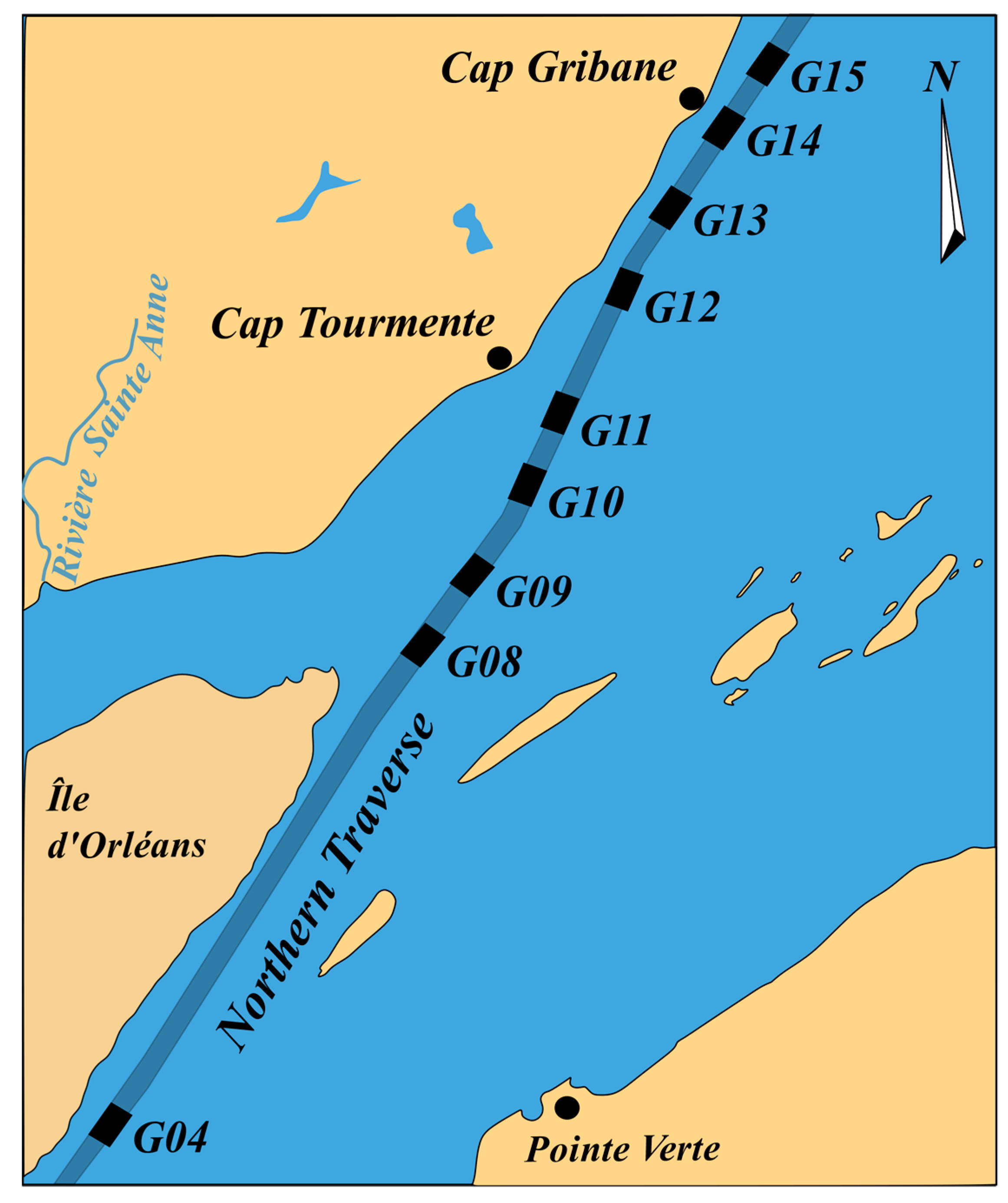
The Northern Traverse is located in the transition zone between the river estuary and the middle estuary of the Saint-Lawrence river. This navigation channel has a width of approximately 305 m and a draft of 12.5 m, which makes it possible to navigate vessels with a draft of 15 m up to Québec City with the tide effect [33]. The sectors considered in the segmentation approach can be observed in Figure 7.
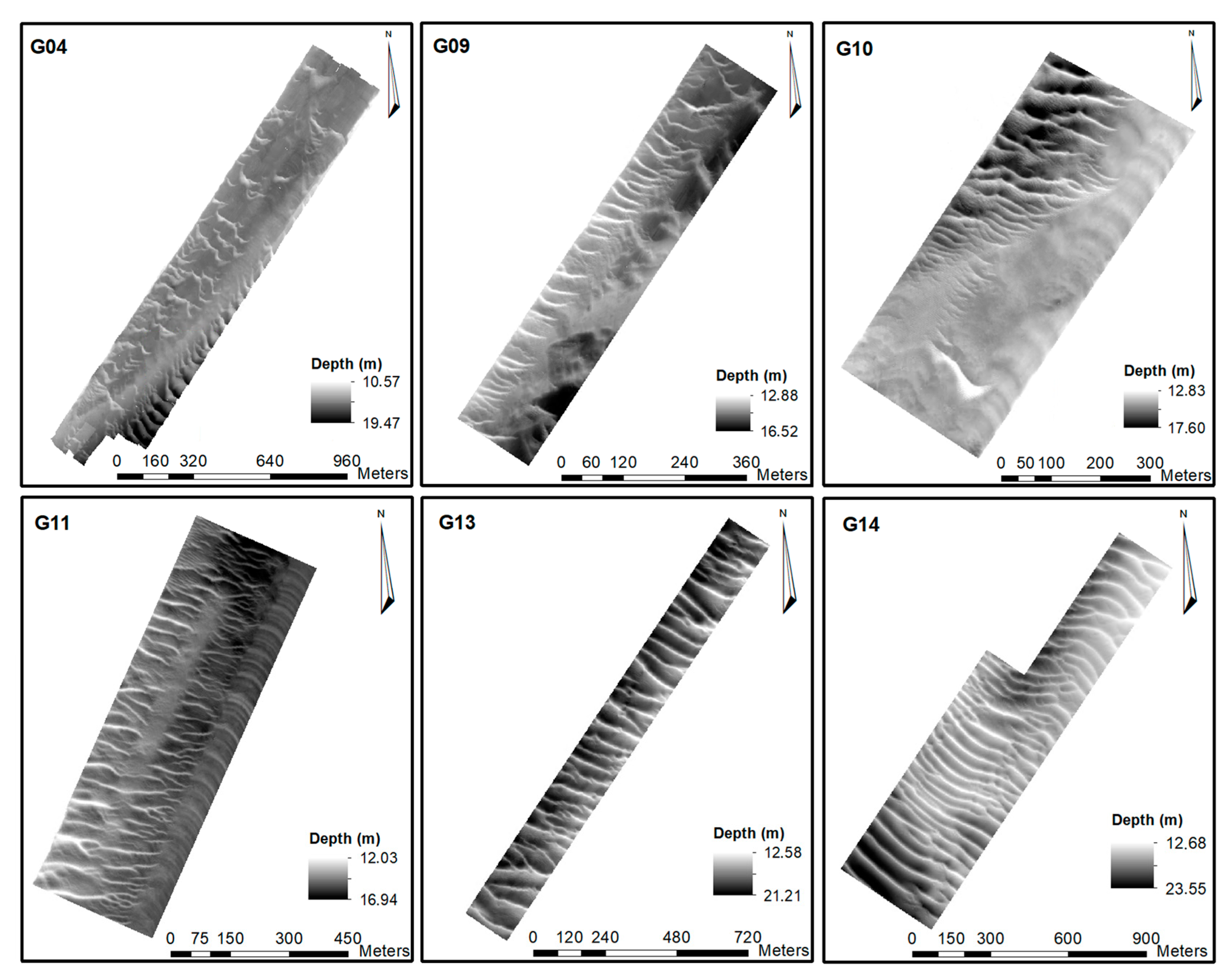
As previously mentioned, the seafloor was modeled from the data provided by the Canadian Hydrographic Service (CHS) and Ocean Group, which consists of regularly spaced points of the seabed. Thus, regular a gridded DBM could be generated for the different sectors. In our study, the DBM resolution was 1 m for all considered sectors. Figure 7 shows nine sectors. However, in our study, we considered 14 DBMs computed over these nine sectors. Consequently, some sectors have more than one DBM (namely sectors G09, G10, G11, and G14). Even if the DBMs are in the same sector, the sedimentary structures on the surface are different due to the high dynamism of the Saint-Lawrence river in the studied zone. Additionally, since the datasets were surveyed in the context of maintenance of the navigation channel, DBMs in the same sector were computed with data acquired at different dates, with a time lapse of a few months to a few years. Specifically, the surveys aimed to detect and dredge the sedimentary structures that could represent a risk for safe navigation. Figure 8 illustrates a few examples of the Northern Traverse DBMs considered in which the different dune configurations on the seabed can be observed.
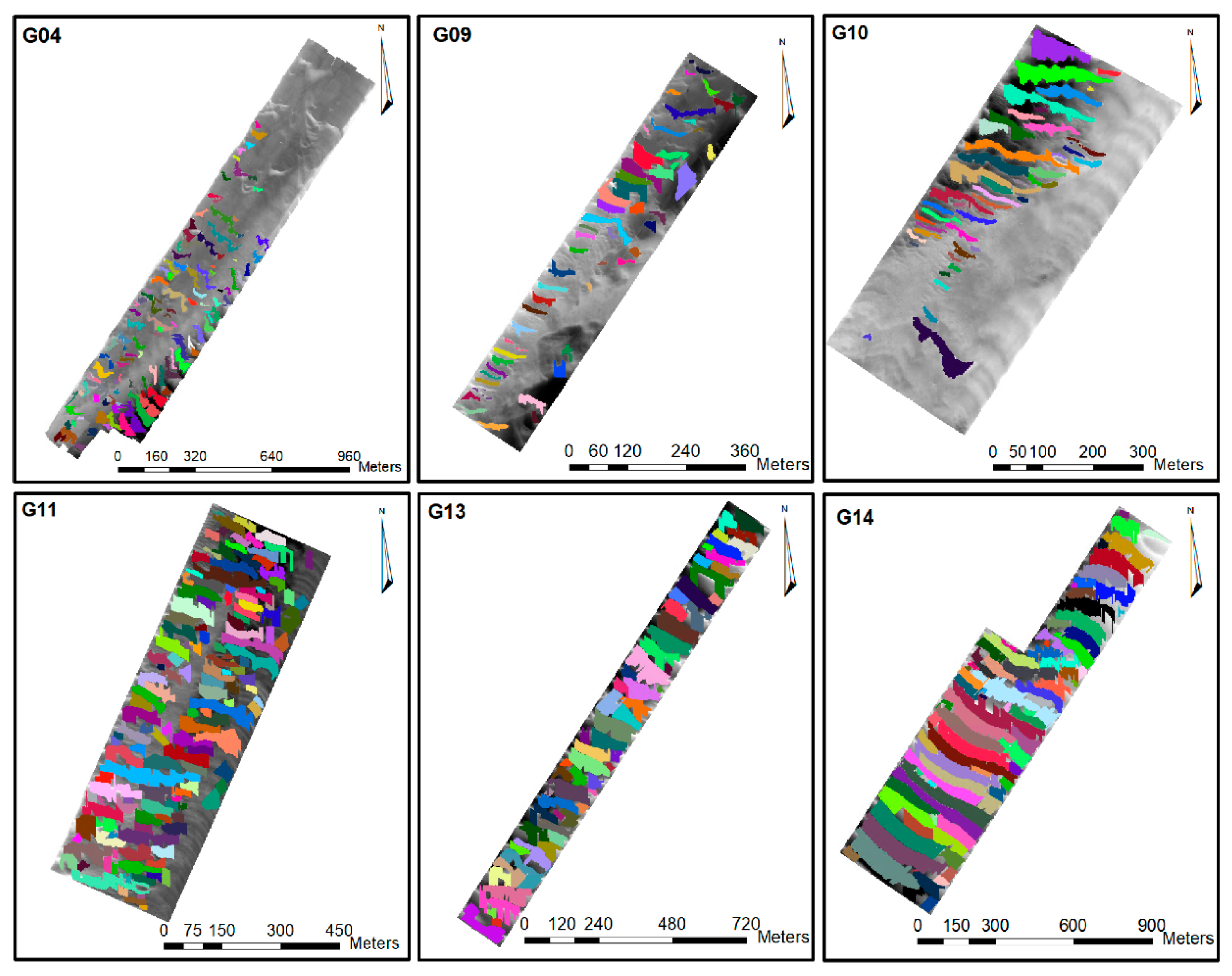
The different DBMs presented in Figure 8 illustrates different configurations of the sedimentary structures present in the seabed of the Northern Traverse, with a depth ranging between 10.50 m and 23.50 m, namely isolated barchan or 3D dunes in G04; sinuous dunes isolated or in a field of dunes in G09, G10, and G11; as well as straight dunes in a field of dunes in G13 and G14. This dune diversity is due to different factors, such as the flow (current) velocity and the grain size. The nine sectors of the Northern Traverse were considered to evaluate the robustness of the proposed segmentation approach by segmenting a large number of sedimentary structures in many different configurations.

5.2. Segmentation Results

The developed segmentation approach from DBM is based on the conceptual model of underwater dunes previously defined. Salient features are first identified by employing the geomorphons [4]. This method uses four parameters to classify the geomorphometry of the sea bottom: the outer search radius, the inner search radius, the flatness threshold, and the flatness distance. The values of the parameters considered in the generation of the geomorphon classes can be observed in Table 2.
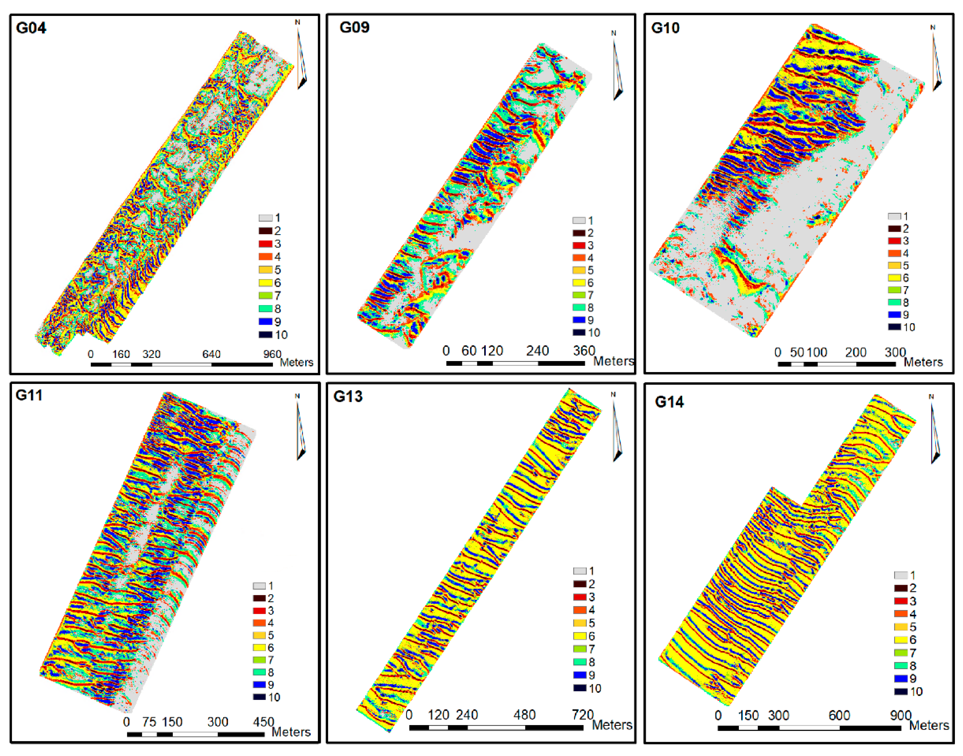
The values of the geomorphon parameters presented in Table 2 come from an adaptation of the sensitivity study conducted in [34]. In this research, the author used the geomorphon algorithm to segment the seafloor using three datasets. The first dataset was a flat sea bottom. The second dataset involved slopes and flat areas. The third dataset was acquired in a rocky underwater canyon context. A comparative analysis was conducted in order to determine the relevant values for the geomorphon parameters. It was done using only a subset of all the sectors (surfaces illustrated in Figure 8). A visual comparison involving the dunes identified from the DBM and the results of the geomorphon, as made in [3], yielded the following parameters: 15, 4 and 5, 1 and 1.5, and 2. Please note that two values were used for the inner search radius and the flatness threshold for the sea bottom modeled surfaces. The geomorphon classifications can be observed in Figure 9.
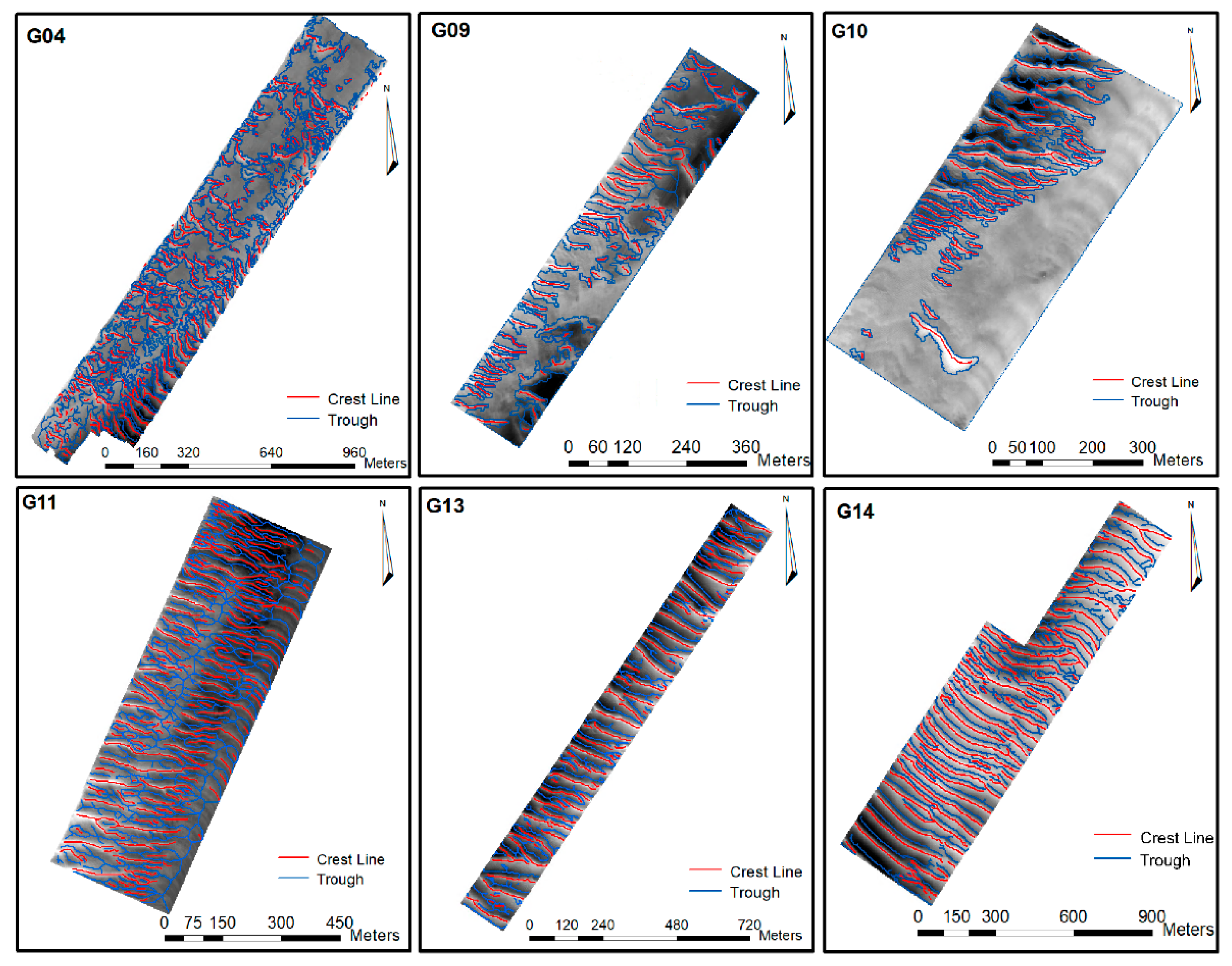
Processes from 2 to 5 from phase I take place considering the geomorphon surfaces generated. Figure 10 illustrates the results of phase I, which are the crest lines and troughs of the dunes identified.
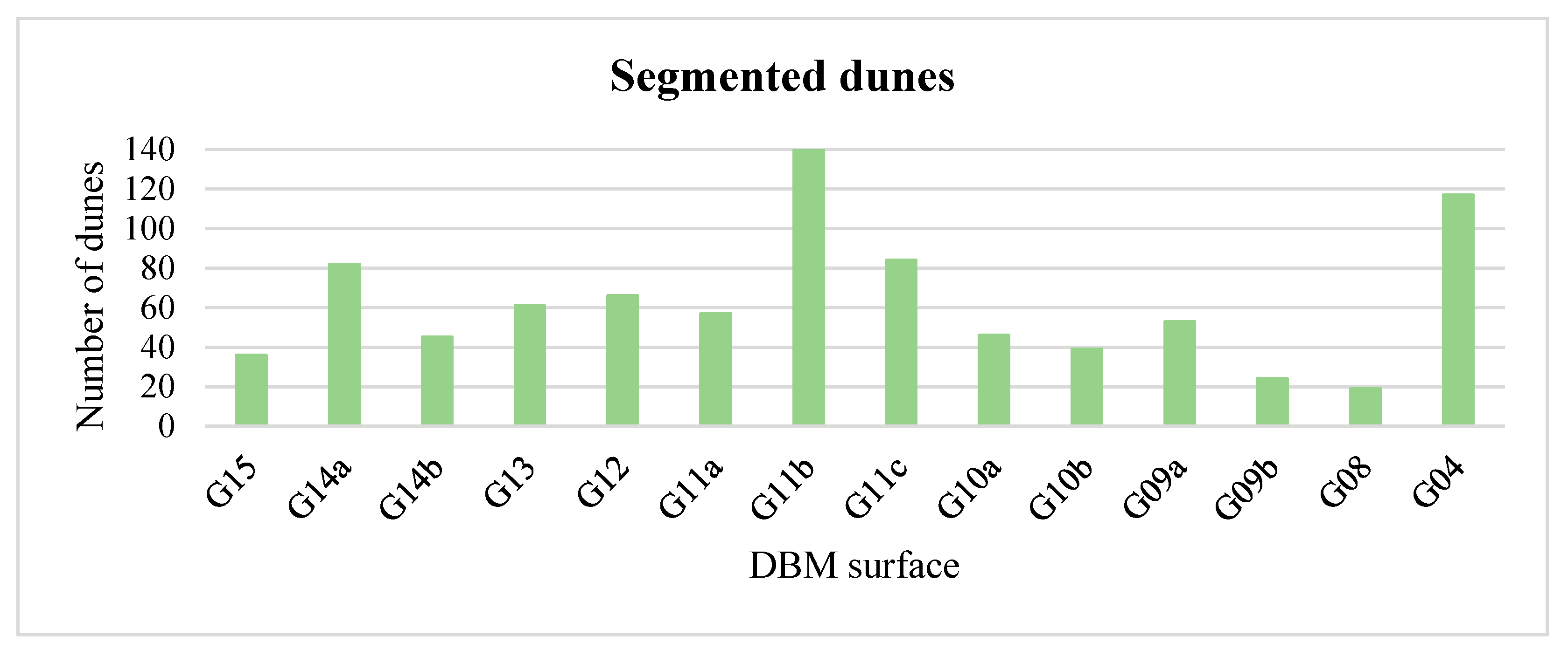
Once the salient features have been identified, the three processes of phase II take place. From the 14 considered DBMs, a total of 882 underwater dunes were segmented. Figure 11 presents the number of segmented dunes for each DBM of the Northern Traverse.
Figure 12 illustrates the dune objects segmented from the DBM shown in Figure 8.
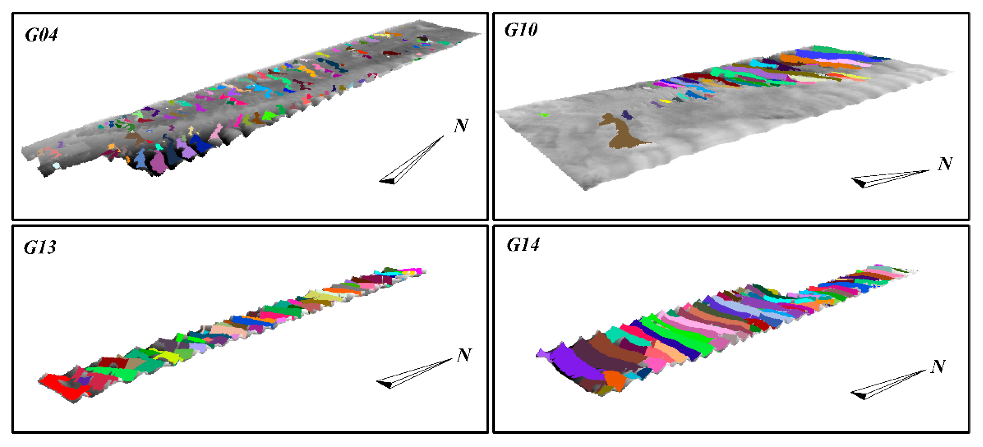
Figure 13 presents a 3D view of G04, G10, G13, and G14 surfaces to better visualize the segmented dunes.
The results of the dune segmentation approach are analyzed in the next section.

5.3. Segmentation Result Analysis and Discussion

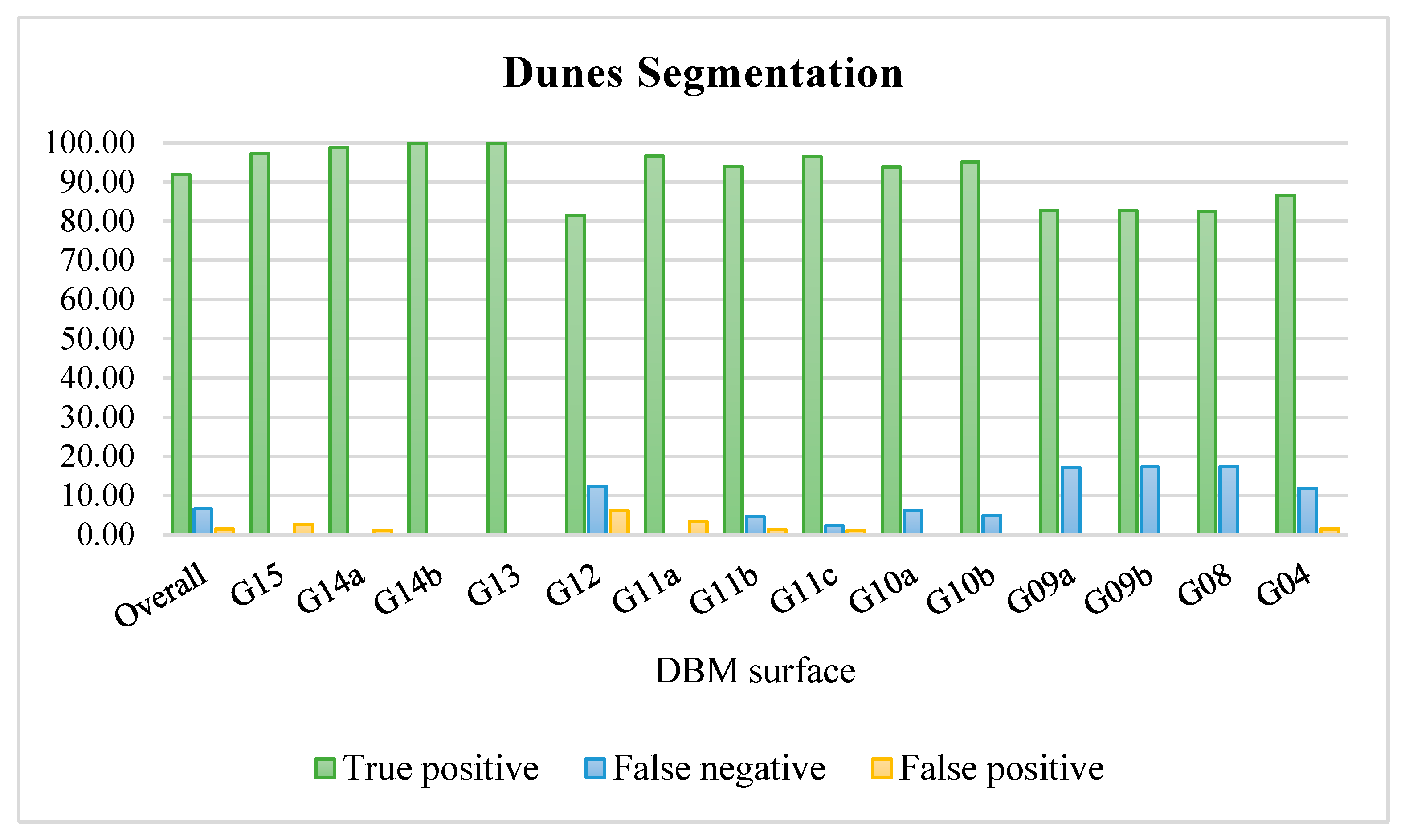
In order to analyse the results presented in the previous section and assess the performance of the proposed segmentation method, a ground truth was built for each DBM by manually selecting the dunes on the surface. Three performance measures were computed by comparing the dunes in the ground truth and the dunes in the segmented DBM, namely true positive, false positive, and false negative rate. A true positive is considered when a minimum of 50% of the segmented area of the dune coincides with its area in the ground truth. A false positive is considered when the area of the segmented dune coincides with less than 50% in the ground truth or when this dune does not have a related dune in the ground truth. A false negative is when the proposed method fails to segment a dune existing in the ground truth (adapted from [35]). Figure 14 summarises the three performance measures for each DBM.
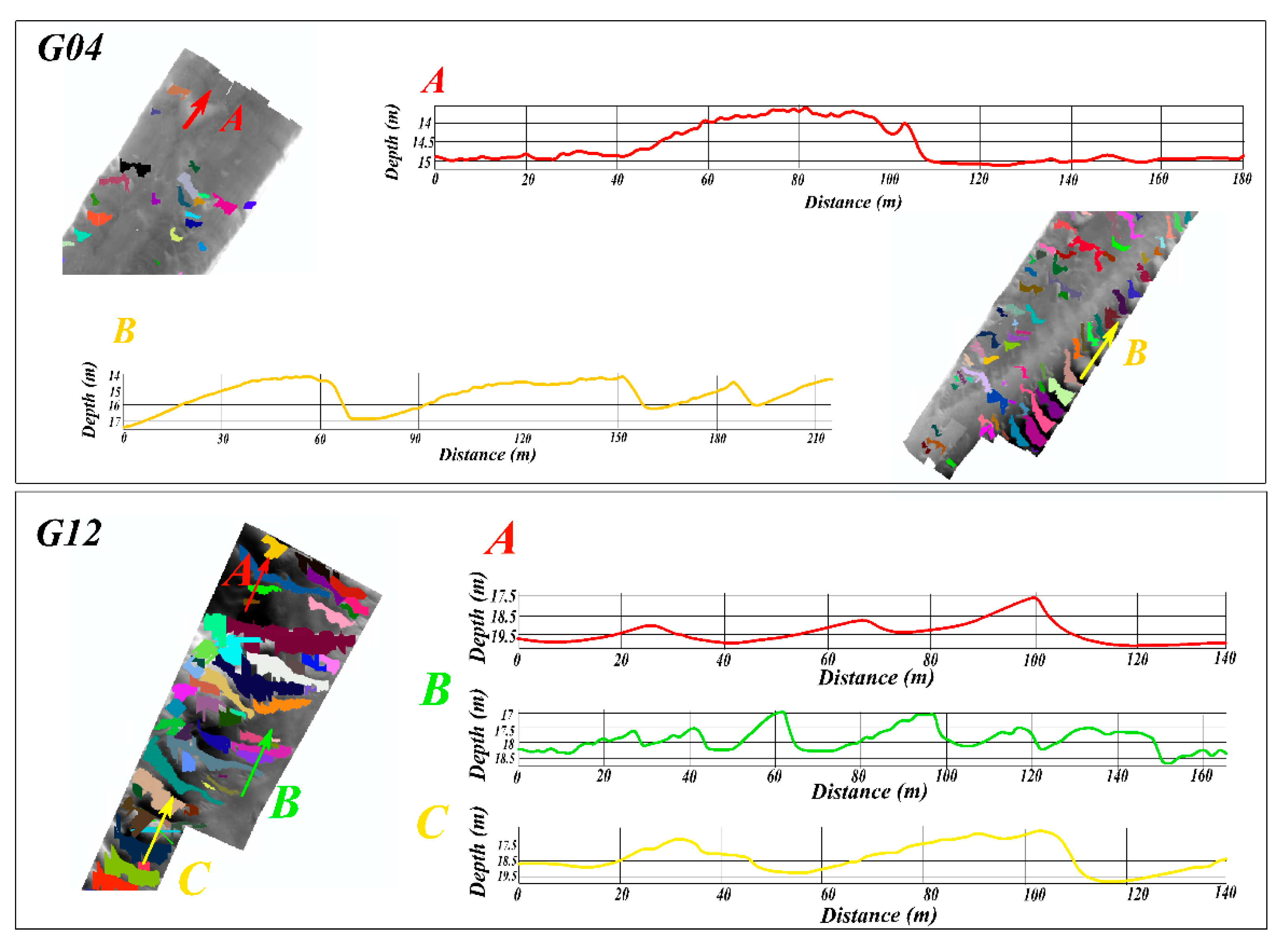
The overall performance of the proposed dune segmentation method, averaging the results over all DBMs, is 91.9% of true positive, 6.6% of false negative, and 1.5% of false positive. This means that out of the 882 segmented dunes, 868 were true positive, 14 were false positive, and 62 were false negative. Among the 14 DBMs, nine had a true positive rate higher than 93%, with two even reaching 100% (i.e., G13 and G14b). The true positive rate of G14a and G15 was greater than 97%, with only one false positive detection each. The segmented dunes from surfaces G14a and G13 can be observed in Figure 12 and Figure 13. Among the false positives, 35% were small structures present in the seafloor detected as dunes, and 65% were structures that had been partially dredged. These dunes were altered by machinery and do not have clearly delineated salient features required for the dune segmentation. An example of dredged dunes in different surfaces can be observed in Figure 15.
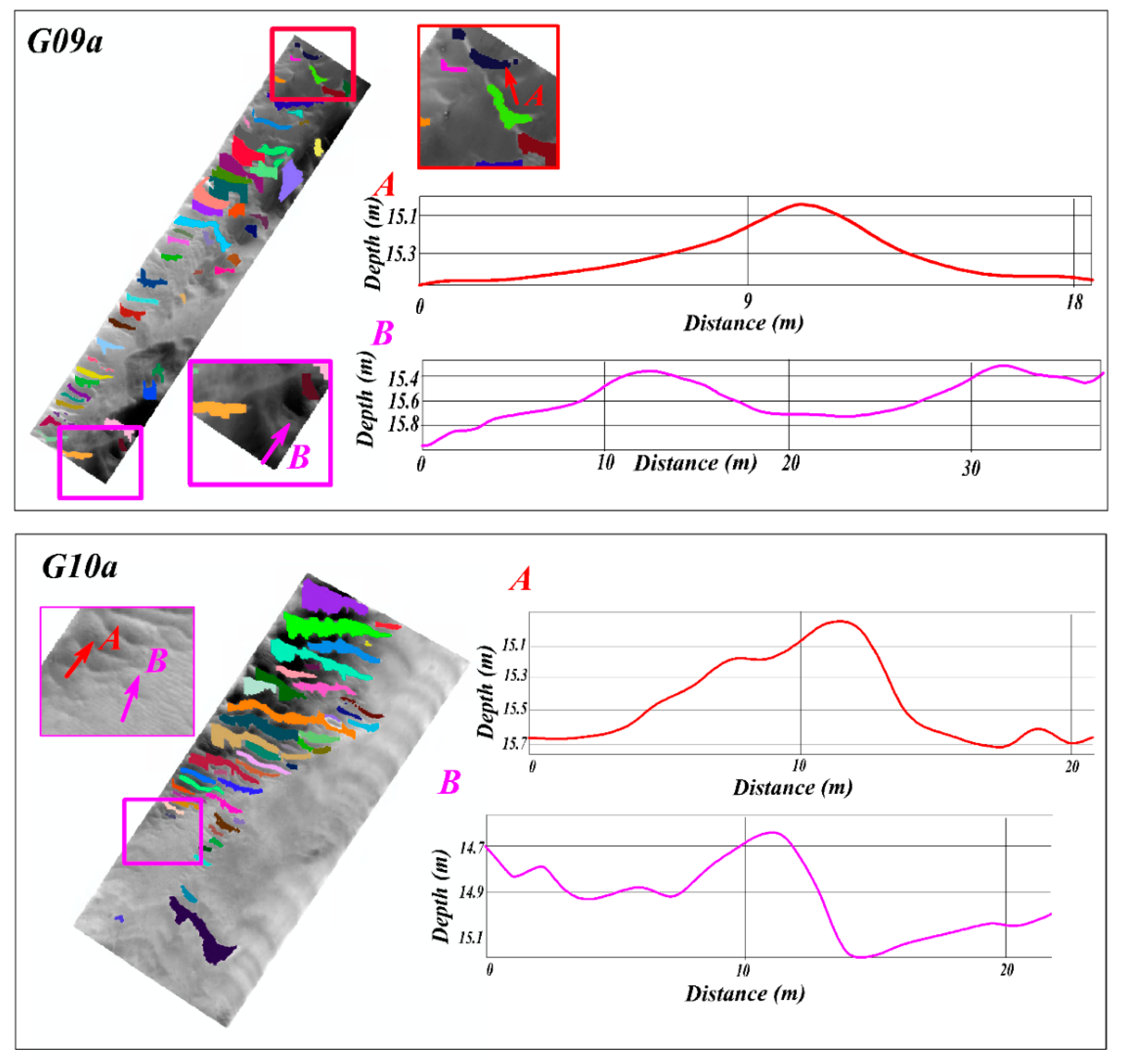
Relying on profiles A and B of G04, we can infer the dunes were not identified because their crests were dredged and therefore were not detected. In B, only the portion of the dune that was not dredged was detected. The highest false positive rate was observed in G12, with 6.2%. In this surface, among the 81 identified sedimentary structures, 5 false positives were associated with the central dune in profile C of G12 presented in Figure 15. This specific dune does not have a well delineated crest line, and therefore 5 small structures, possibly ridges, were detected instead in this partially dredged dune. Profile A of G12 shows dunes correctly segmented from G12 DBM. In other surfaces, false positives were also related to the absence of a well delineated crest line. Regarding the false negative, after analyzing the statistics of this performance measure, we conclude that its occurrence was related to the presence of small dunes on the DBM. In fact, the segmentation of these dunes was not possible with our method since the geomorphometric classification does not identify the crest lines of these sedimentary structures. The false negatives in the results are mostly associated with the resolution of the DBM. These smaller structures responsible for the false negative should be detected with a finer resolution of the DBM. Figure 16 illustrates four examples of false negative on surfaces G09a and G10a.
Profiles A and B of surface G09a and B of surface G10a show two small dunes with a height below 40 cm, characterizing small dunes. Either the geomorphometric classification did not detect the crest line or the crest was removed by the filtering process. The false negative illustrated in profile A of surface G10a (Figure 16) was also removed by filtering for not having a significant surface to be considered as an underwater dune. After analyzing the false negative, we conclude that the small dunes (height inferior to 40 cm, Table 1) were identified manually, but the segmentation method was not able to identify them. Indeed, in these small structures, the salient features were not properly identified by the geomorphometric analysis. Consequently, these small dunes were not segmented. In the proposed method, the identification of the salient features is dependent of the scale of the analysis, as highlighted in [3]. Indeed, the identification of the salient features of the dunes is related to the resolution of the DBM. The resolution of the bathymetric surface is related to the bathymetric data uncertainty and quality as proposed in [36]. However, in this research, the DBMs of the Northern Traverse were generated using a point cloud with regularly spaced points. Therefore, based on the density of the point cloud, the 1 m resolution was chosen. Then, the identification of small dunes with a wavelength between 0.6 m and 5 m and a height between 0.075 m and 0.4 m becomes impractical, since the DBMs considered in the Northern Traverse have a pixel resolution of 1 m.

6. Conclusions

A novel method dedicated to underwater dune segmentation was proposed in this paper. This method is based on the underwater dunes formalized concept through the conceptual model. The segmentation method relies on a geomorphometric analysis of the seabed and mathematical morphology operations to delineate the salient features of the dunes. Then, an OBIA approach was used to match the salient features, thus generating the dune objects. To validate the segmentation method, more than 850 dunes were segmented on the Northern Traverse of the Saint-Lawrence river. The segmented dune objects displayed significant diversity regarding their characteristics, namely straight dunes; tridimensional dunes; barchan dunes; dunes belonging to a field of dunes (adjacent structures); and isolated dunes.
The originality of our segmentation method lies in the dune conceptual model at the basis of this approach. Thanks to this model, identifying the dunes requires only the identification of the dune salient features (crest line, stoss trough, and lee trough) rather than all the dune components. These features delineate the dune object itself. Therefore, formalizing the conceptual and operational models provides an efficient way to segment underwater dunes from the DBM. Indeed, these models can be reused with different datasets with minor adjustments. As an example, the geomorphometric parameters involved in the identification of the salient features can be adapted for different contexts and scales of analysis. In addition, the geomorphon algorithm is not the only one that could be used to conduct the geomorphometric analysis of the DBM (i.e., phase 1 of the proposed method).
The paper focused on underwater dunes situated in a fluvio-marine context. Further experiments will be dedicated to assessing the performance of our method in other contexts (e.g., marine dunes). Additionally, further work should be invested in assessing the impact of DBM with finer and coarser resolutions on the segmentation performances, especially on its capacity to detect small dunes. In addition, relying on the segmentation method, future work will be dedicated to dune classification. Since the conceptual model formalizes the dune by its salient features, these features are not only used to identify them but also should be used to characterize and classify them. The classification should consider the classes well established in the literature (e.g., as in [29]) and extend these categories based on the dune geometry (e.g., asymmetry index, orientation) and expert knowledge (e.g., risk for safe navigation). Future work related to the classification should also consider the backscatter data in order to specify the categories of dunes using the dune geometry and expert knowledge. In fact, if this information is available with the dataset, the segmentation method could be improved by using a multiple input, similarly to what has been proposed in [5] with the BRESS algorithm.

Author Contributions

Conceptualization, W.N.C.; methodology, W.N.C.; validation, W.N.C., S.D. and É.G.; investigation, W.N.C., S.D. and É.G.; resources, S.D. and É.G.; data curation, W.N.C.; writing—original draft preparation, W.N.C.; writing—review and editing, W.N.C., S.D. and É.G.; visualization, W.N.C.; supervision, S.D. and É.G.; project administration, S.D.; funding acquisition, S.D. and É.G. All authors have read and agreed to the published version of the manuscript.

Funding

This research was funded by FRQ-NT (Fonds de Recherche Nature et Technologie Québec), grant number 2018-PR-206875, and the NSERC (Natural Sciences and Engineering Research Council) Discovery, grant number 2016-05129.

Data Availability Statement

The data are not publicly available. The data were a courtesy of the Canadian Hydrographic Service and Ocean Group for this research. Code implementation can be provided upon request to the corresponding author.

Acknowledgments

The authors would like to thank Université Laval for providing access to the equipment and laboratories to conduct this research. In addition, they would like to thank the CHS (Canadian Hydrographic Service) and Ocean group by providing the data that was used in this research. They would also like to thank Mitacs, Fonds Joncas, CN (Canadien National), Faculté de Foresterie, Géographie et Géomatique de l’Université Laval, and the Canadian Institute of Geomatics (CIG) for their financial support. We must thank the companies for the licenses of the software, such as QPS for Qimera 1.7.6 and MATLAB R2019a—Classroom use.

Conflicts of Interest

The authors declare no conflict of interest.

References

  1. Debese, N.; Jacq, J.J.; Garlan, T. Extraction of sandy bedforms features through geodesic morphometry. Geomorphology 2016, 267, 82–97. [Google Scholar] [CrossRef] [Green Version]
  2. Ogor, J. Design of Algorithms for the Automatic Characterization of Marine Dune Morphology and Dynamics. Ocean, Atmosphere. Ph.D. Thesis, ENSTA-Bretagne, Brest, France, 2018. [Google Scholar]
  3. Di Stefano, M.; Mayer, L.A. An automatic procedure for the quantitative characterization of submarine bedforms. Geosciences 2018, 8, 28. [Google Scholar] [CrossRef] [Green Version]
  4. Jasiewicz, J.; Stepinski, T.F. Geomorphons—a pattern reconigtion approach to classification and mapping of landforms. Geomorphology 2012, 182, 147–156. [Google Scholar] [CrossRef]
  5. Masetti, G.; Mayer, L.A.; Ward, L.G. A Bathymetry- and Reflectivity-Based Approach for Seafloor Segmentation. Geosciences 2018, 8, 14. [Google Scholar] [CrossRef] [Green Version]
  6. Lecours, V.; Dolan, M.F.J.; Micallef, A.; Lucieer, V.L. A review of marine geomorphometry, the quantitative study of the seafloor. Hydrol. Earth Syst. Sci. 2016, 20, 3207–3244. [Google Scholar] [CrossRef] [Green Version]
  7. Lucieer, V.; Lecours, V.; Dolan, M.F.J. Charting the course for future developments in marine geomorphometry: An introduction to the special issue. Geosciences 2018, 8, 477. [Google Scholar] [CrossRef] [Green Version]
  8. Wood, J. The Geomorphological Characterization of Digital Elevation Models. Ph.D. Thesis, University of Leicester, Leicester, UK, 1996. [Google Scholar]
  9. Dragut, L.; Blaschke, T. Automated classification of landform elements using object-bases image analysis. Geomorphology 2006, 81, 330–344. [Google Scholar] [CrossRef]
  10. Blaschke, T. Object based image analysis for remote sensing. ISPRS J. Photogramm. Remote Sens. 2010, 65, 2–16. [Google Scholar] [CrossRef] [Green Version]
  11. Benz, U.C.; Hofmann, P.; Willhauck, G.; Lingenfelder, I.; Heynen, M. Multi-resolution, object oriented fuzzy analysis of remote sensing data for GIS-ready information. ISPRS J. Photogramm. Remote Sens. 2004, 58, 239–258. [Google Scholar] [CrossRef]
  12. Castilla, G.; Hay, G.J. Image objects and geographic objects. In Object-Based Image Analysis, Lecture Notes in Geoinformation and Cartography; Blaschke, T., Lang, S., Hay, G.J., Eds.; Springer: Berlin/Heidelberg, Germany, 2008; Chapter 1.5; 20p. [Google Scholar] [CrossRef]
  13. Soille, P.; Pesaresi, M. Advances in mathematical morphology applied to geosciences and remote sensing. IEEE Trans. Geosci. Remote Sens. 2002, 40, 2042–2055. [Google Scholar] [CrossRef]
  14. López-Ornelas, E. High resolution images: Segmenting, extracting information and GIS integration. World Acad. Sci. Eng. Technol. 2009, 54, 172–177. [Google Scholar]
  15. d’Oleire-Oltmanns, S.; Eisank, C.; Dragut, L.; Blaschke, T. An object-based workflow to extract landforms at multiple scale from two distinct data types. IEEE Geosci. Remote Sens. Lett. 2013, 10, 947–951. [Google Scholar] [CrossRef]
  16. Ismail, K.; Huvenne, V.A.I.; Masson, D.G. Objective automated classification technique for marine landscape mapping in submarine canyons. Mar. Geol. 2015, 362, 17–32. [Google Scholar] [CrossRef] [Green Version]
  17. Dragut, L.; Tiede, D.; Levick, S.R. ESP: A tool to estimate scale parameter for multiresolution image segmentation of remotely sensed data. Int. J. Geogr. Inf. Sci. 2010, 24, 859–871. [Google Scholar] [CrossRef]
  18. Diesing, M.; Thorsnes, T. Mapping of cold-water coral carbonate mounds based on geomorphometric features: An object-based approach. Geosciences 2018, 8, 38. [Google Scholar] [CrossRef] [Green Version]
  19. Sowers, D.C.; Masetti, G.; Mayer, L.A.; Johnson, P.; Gardner, J.V.; Armstrong, A.A. Standardized Geomorphic Classification of the Seafloor within the United States Atlantic Canyons and Continental Margin. Front. Mar. Sci. 2020, 7, 9. [Google Scholar] [CrossRef] [Green Version]
  20. Deng, Y. New trends in digital terrain analysis: Landform definition, representation, and classification. Prog. Phys. Geogr. 2007, 31, 405–419. [Google Scholar] [CrossRef]
  21. Arvor, D.; Belgiu, M.; Falomir, Z.; Mougenot, I.; Durieux, L. Ontologies to interpret remote sensing images: Why do we need them? Giscience Remote Sens. 2019, 56, 911–939. [Google Scholar] [CrossRef] [Green Version]
  22. Guilbert, E.; Moulin, B.; Cortés Murcia, A. A conceptual model for the representation of landforms using ontology design patterns. ISPRS Annals of the Photogrammetry, Remote Sensing and Spatial Information Sciences, Volume III-2. In Proceedings of the XXIII ISPRS Congress, Prague, Czech Republic, 12–19 July 2016. 8p. [Google Scholar]
  23. Guilbert, E.; Moulin, B. Towards a Common Framework for the Identification of Landforms on Terrain Models. ISPRS Int. J. Geo-Inf. 2017, 6, 12. [Google Scholar] [CrossRef]
  24. Ferret, Y. Morphodynamique de Dunes Sous-Marines en Contexte de Plate-Forme Mégatidale (Manche Orientale). Approche Multi-Échelles Spatio-Temporelles. Interfaces Continentales, Environnement. Ph.D. Thesis, Université de Rouen, Mont-Saint-Aignan, France, 2011. [Google Scholar]
  25. Nichols, G. Sedimentology and Stratigraphy, 2th ed.; Chapter 4 Processes of Transport and Sedimentary Structures; Wiley-Blackwell, A John Wiley & Sons, Ltd., Publication: West Sussex, UK, 2009; pp. 44–68. [Google Scholar]
  26. Garlan, T. Study on Marine Sandwave Dynamics. Int. Hydrogr. Rev. 2007, 8, 26–37. [Google Scholar]
  27. Thibaud, R.; Del Mondo, G.; Garlan, T.; Mascret, A.; Carpentier, C. A Spatio-Temporal Graph Model for Marine Dune Dynamics Analysis and Representation. Trans. GIS 2013, 17, 742–762. [Google Scholar] [CrossRef]
  28. Boggs, S. Principles of Sedimentology and Stratigraphy, 4th ed.; Chapter 4 Sedimentary structures; Chapter 9 Marginal Marine Environments; Pearson Prentice Hall: Upper Saddle River, NJ, USA, 2006; pp. 74–116, 289–333. ISBN 0-13-154728-3. [Google Scholar]
  29. Ashley, G.M. Classification of large-scale subaqueous bedforms: A new look to an old problem. J. Sediment. Petrol. 1990, 60, 160–172. [Google Scholar]
  30. Gutierrez, R.R.; Abad, J.D.; Parsons, D.R.; Best, J.L. Discrimination of bed form scales using robust spline filters and wavelet transforms: Methods and application to synthetic signals and bed forms of the Rio Paraná, Argentina. J. Geophys. Res. Earth Surf. 2013, 118, 1400–1419. [Google Scholar] [CrossRef]
  31. van der Mark, C.F.; Blom, A. A New & Widely Applicable Bedform Tracking Tool; University of Twente: Enschede, The Netherlands, 2007; 44p. [Google Scholar]
  32. Garlan, T. GIS and Mapping of Moving Marine Sand Dunes. Presented at the 24th International Cartography Conference, (ICC 2009), Santiago, Chile, 15–21 November 2009. [Google Scholar]
  33. Comité de Concertation Navigation de Saint Laurent Vision 2000. Stratégie de Navigation Durable Pour le Saint-Laurent; Ministère des Transports du Québec et Pêches et Océans Canada: Québec, QC, Cananda, 2004; 114p. [Google Scholar]
  34. Dupont, V. Élaboration D’une Méthode D’extraction de Plans par Croissance de Régions Dans un Nuage de Points Bathymétriques Servant à Alimenter des Estimateurs D’erreur Hydrographique. Master’s Thesis, Université Laval, Québec, QC, Cananda, 2020; 120p. [Google Scholar]
  35. Nguyen, T.H.; Daniel, S.; Guériot, D.; Sintès, C.; Le Caillec, J.M. Super-resolution-based snake model—an unsupervised method for large-scale building extraction using airborne LiDAR data and optical image. Remote Sens. 2020, 12, 1702. [Google Scholar] [CrossRef]
  36. Canadian Hydrographic Service (CHS). Traitement et Analyse de Données Bathymétriques de CUBE; Pêches et Océans Canada: Agassiz, BC, Canada, 2012; 7p. [Google Scholar]
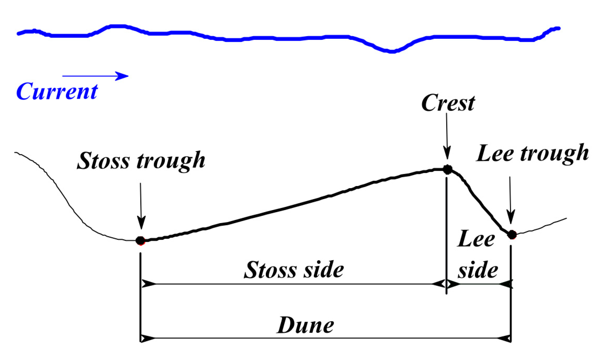
Figure 1. Representation of a dune profile with the crest line, the lee and stoss troughs, and the lee and stoss sides.
Geosciences 11 00361 g001
Figure 2. Correlation between the flow velocity, grain size sediment, and the sedimentary structure formed, adapted from [25].
Geosciences 11 00361 g002
Figure 3. Example of the crest lines (red) and troughs (blue) of a field of dunes identified from a DBM. In the magnified view (i.e., black frame), we can observe that one trough (yellow) can be related to more than one dune (identified with the magenta crest lines).
Geosciences 11 00361 g003
Figure 4. Conceptual model of underwater dunes.
Geosciences 11 00361 g004
Figure 5. Phase I of the dune segmentation approach.
Geosciences 11 00361 g005
Figure 6. Phase II of the dune segmentation approach.
Geosciences 11 00361 g006
Figure 7. Studied sectors (e.g., G04, G08,…, G15) of the Northern Traverse of the Saint-Lawrence river.
Geosciences 11 00361 g007
Figure 8. DBM of the sectors G04, G09, G10, G11, G13, and G14 of the Northern Traverse.
Geosciences 11 00361 g008
Figure 9. Geomorphon surface of the DBM illustrated in Figure 8, where 1 represents flat, 2 summit, 3 ridge, 4 shoulder, 5 spur, 6 slope, 7 hollow, 8 footslope, 9 valley, 10 depression.
Geosciences 11 00361 g009
Figure 10. The salient features of the underwater dunes identified for sectors G04, G09, G10, G11, G13, and G14 of the Northern Traverse. The salient features (crest lines in red and troughs in blue) are superimposed on the DBM.
Geosciences 11 00361 g010
Figure 11. Number of segmented dunes by DBM surface.
Geosciences 11 00361 g011
Figure 12. Segmented dunes of the sectors G04, G09, G10, G11, G13, and G14 of the Northern Traverse. The different dune objects are represented by colored polygons. The dune objects are superimposed on the DBM.
Geosciences 11 00361 g012
Figure 13. Three-dimensional visualisation of the surfaces G04, G10, G13, and G14 with segmented dunes (colored). Please note the vertical exaggeration of 5.
Geosciences 11 00361 g013
Figure 14. Performance measures of the proposed method, namely true positive, false negative, and false positive rates. Please note that we present the overall performance considering all the surfaces.
Geosciences 11 00361 g014
Figure 15. False positive dredged dunes segmented from surfaces G04 and G12. The arrows illustrate the profiles and their directions on the DBM.
Geosciences 11 00361 g015
Figure 16. False negative of surfaces G09a and G10a. The arrows illustrate the profiles and their directions on the DBM.
Geosciences 11 00361 g016
Table 1. Dune classification, adapted from [29].
ParametersSmallMediumLargeVery Large
Wavelength (m)0.6 to 55 to 1010 to 100More than 100
Height (m)0.075 to 0.40.4 to 0.750.75 to 5More than 5
Table 2. Values of the parameters used in the generation of geomorphon classes.
ParameterValues
Outer search radius[5, 10, 15, 20, 25, 30]
Inner search radius[1, 2, 3, 4, 5]
Flatness threshold[0.5, 1, 1.5, 2, 2.5, 3]
Flatness distance[0, 0.5, 1, 2, 3, 4, 5]
Publisher’s Note: MDPI stays neutral with regard to jurisdictional claims in published maps and institutional affiliations.