Abstract
Tokyo, which is located near the boundary between the North American and Philippine Sea plates, has been frequently struck by large earthquakes throughout the Holocene. The 1923 Taisho Kanto Earthquake is a rare historical earthquake that can be reconstructed in detail because abundant datasets were collected by investigations performed just after the earthquake. We examined 13,000 borehole logs from the Tokyo and Nakagawa lowlands to clarify the distribution and thickness of incised-valley fills and soft marine mud that had accumulated since the Last Glacial Maximum (LGM) on a grid with a resolution of 150 m × 150 m. We compared these datasets with the distribution of wooden house damage ratios caused by the Taisho Kanto Earthquake. Our results showed that the thickness of the soft mud, but not that of the incised-valley fills, was strongly correlated with the wooden house damage ratio. The mud content was >60%, water content was >30%, and S-wave velocity was ca. 100 m/s in the soft Holocene marine mud. The wooden house damage ratio was highest where the soft mud thickness was 20 m, because in those areas, both the soft mud and the wooden houses resonated with a natural period of ca. 1 s.
1. Introduction
Tokyo is one of the largest cities in the world with a population of 37.4 million (2021) [1]. Seismic hazard is high in the Tokyo area due to its proximity to an active plate boundary and its underlying geological structure [2]. Tokyo is located near the triple junction of the North American Sea, Philippine Sea, and Pacific plates, and it lies 80 km northeast of the Sagami Trough, where the Philippine Sea Plate is subducting beneath the North American Sea Plate. Subduction zone earthquakes have struck Tokyo at 500- to 2800-year intervals since the middle Holocene [3,4]. The 1703 Genroku Kanto Earthquake (M8.2) and the 1923 Taisho Kanto Earthquake (M7.9) are well-known historical earthquakes with epicenters in the Sagami Trough. The Taisho Kanto Earthquake was especially well investigated by the Geological Survey of Japan and the Earthquake Research Institute of the University of Tokyo beginning just after the earthquake (e.g., [5,6,7]), and these investigations produced abundant data on the distribution of the incised-valley soft sediment fills that accumulated after the Last Glacial Maximum (LGM), tectonic movements, and earthquake damage, which make it possible to reconstruct the earthquake disaster in detail. As a result, it has been revealed that 370,000 houses collapsed and 105,000 people were killed due to the Taisho Kanto Earthquake [8].
The 1923 Taisho Kanto Earthquake disaster has been mainly assessed on the basis of the collapse ratios of houses because most houses were wooden at the time of the earthquake. Kawazumi [9] and Ohsaki [10] were the first to relate wooden house damage to characteristics of the shallow subsurface by showing that the damage ratio of wooden houses increased with the thickness of the post-LGM incised-valley fills. Kaizuka and Matsuda [11] compiled damage ratios of wooden houses across the entire Kanto Plain and showed that, although house damage was generally small in areas far from the epicenter, damage to houses on the alluvial plains could be great, even far from the epicenter. In the Tokyo Lowland, the damage ratio of wooden houses was largest in areas where post-LGM incised-valley fills were ca. 30 m thick because both the wooden houses and the incised-valley fills resonated with a natural period of ca. 1 s [12,13,14,15]. Recently, earthquake simulations have also clarified that ground motion with a period of ca. 1 s is amplified in areas with thick post-LGM incised-valley fills [16]. However, less is known about the distribution of post-LGM incised-valley fills and their relation to the earthquake damage in the Nakagawa Lowland, to the north of the Tokyo Lowland, where the post-LGM incised-valley fills consist mainly of notably soft mud. In general, it is known that near-surface geology and earthquake damage are strongly related, as is clarified from the studies in southern Italy for example [17,18].
Since 2002, the Geological Survey of Japan has been investigating the post-LGM incised-valley fills beneath the Tokyo and Nakagawa lowlands on the Kanto Plain, central Japan, with the aim of mitigating earthquake disasters (e.g., [19,20]). These studies have examined: (1) sedimentary facies, depositional age, and physical properties of the post-LGM incised-valley fills by referring to stratotype cores; (2) the temporal and spatial distribution of the stratigraphy and physical properties of the post-LGM incised-valley fills by comparing thousands of borehole logs obtained for geotechnical purposes with the stratotype cores; and (3) simulated earthquake ground motions in relation to the spatial distribution of physical properties of the post-LGM incised-valley fills.
In this study, we examined 13,000 borehole logs, which were previously reported by Tanabe et al. [21] and Tanabe and Ishihara [22], to compile the distribution and thickness of the post-LGM incised-valley fills and to investigate the distribution and thickness of the soft mud in the Tokyo and Nakagawa lowlands. Subsequently, we compared these datasets with the damage ratio distribution of wooden houses following the Taisho Kanto Earthquake [11]. The physical properties of the soft mud were in three stratotype cores obtained from areas with high house damage ratios in the Nakagawa Lowland [20]. This study is a first attempt to reveal the relationship between the stratigraphy, distribution, and thickness of post-LGM incised-valley fills and soft mud and the house damage ratio in a relatively wide area that includes both the Tokyo and Nakagawa lowlands although a part of this study is initially reported by Stafleu et al. [23].
2. Study Area
The Kanto Plain is situated to the northeast of the Sagami Trough in a sedimentary basin filled with a 3-km-thick sequence of Neogene and Quaternary deposits. The plain mainly comprises uplands that formed after Marine Isotope Stage (MIS) 5e and alluvial lowlands that formed after the LGM (Figure 1).
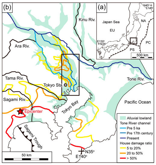
Figure 1.
Index map. (a) The tectonic setting of the Japanese islands. EU, Eurasian Plate; NA, North American Sea Plate; PH, Philippine Sea Plate; PC, Pacific Plate. (b) Kanto Plain. The house damage ratio refers to damage caused to wooden houses by the 1923 Taisho Kanto Earthquake [9]. In general, the house damage ratio decreased outward from the epicenter, but it was great in northeast of the Tokyo Station (Tokyo and Nakagawa lowlands), despite their distance from the epicenter.
Our study area included the Tokyo Lowland east of Tokyo Station and the Nakagawa Lowland, which lies to the north of the Tokyo Lowland (Figure 2). The Tokyo and Nakagawa lowlands are bounded on the east by the Shimosa Upland. On the west, the Nakagawa Lowland is bounded by the Omiya Upland, and the Tokyo Lowland by the Musashino Upland. Marine terraces situated on the Shimosa and Musashino uplands at 20 m above Tokyo Peil (TP) formed during MIS 5e, when the relative sea level was 14 m TP [24]. Therefore, the study area has been practically tectonically stable since MIS 5e. The study area lacks any active faults. Beneath the Omiya Upland, relatively soft MIS 5e age mud (lower Kioroshi Formation) fills the valleys that were incised during MIS 6 [25]. The uplands in the study area comprise, in descending order, the MIS 5e Shimosueyoshi, the MIS 5a Musashino, and the MIS 3 Tachikawa terraces (e.g., [26]).
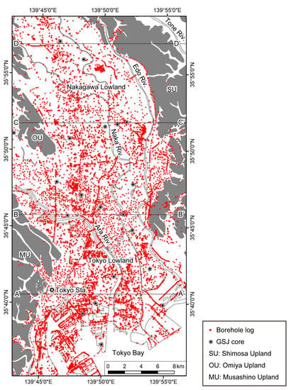
Figure 2.
Locations of the borehole logs used in this study and of the four studied cross-sections. GSJ cores are stratotype cores obtained or analyzed by the Geological Survey of Japan. The borehole plots are after Tanabe et al. [21] and Tanabe and Ishihara [22].
From east to west in the study area, the Edo, Naka, and Ara rivers flow southward into Tokyo Bay (Figure 2). The Tone River flowed along the course of the present Ara River prior to 5 ka, and then along the course of the present Naka River until the 17th century, when in order to prevent flooding in Tokyo, it was diverted to flow directly into the Pacific Ocean instead of Tokyo Bay [20,27] (Figure 1). The present Tone River is the largest distributary in Japan (catchment area, 16,840 km2), with a discharge of 8.7 km3/yr (290 m/s) and a sediment yield of 3 Mt/yr (95 kg/s) [28].
Until the LGM, the Ara River and the Naka River valleys converged in the Tokyo Lowland to form the Paleo-Tokyo River, which flowed into Tokyo Bay [21,26,29,30,31]. The valleys of these rivers became filled with fluvial and marine sediments deposited during the deglacial sea-level rise. The post-LGM incised-valley fills in the Tokyo and Nakagawa lowlands unconformably overlie the Middle to Late Pleistocene Shimosa Group; in stratigraphical order, they comprise gravel beds deposited by a braided river system, alternating beds of sand and mud deposited by a meandering river system, upward-fining sand and mud beds of an estuary system, upward-coarsening sand beds of a spit system, and upward-coarsening sand and mud beds of a delta system [20]. The spit system is distributed locally along the western margin of the Shimosa Upland. The unconformity between the Shimosa Group and the post-LGM incised-valley fills can be regarded as the sequence boundary (SB). The boundary of the braided/meandering river system is the transgressive surface (TS), that of the meandering river and estuary systems is the initial flooding surface (IFS), and the estuary/delta system boundary is the maximum flooding surface (MFS) [32,33]. The MFS has been dated to 7 ka in the Tokyo and Nakagawa lowlands [20].
Sea level was 2–3 m higher than the present level in the area north of Tokyo Bay during 7–4 ka [34]. Marine beds deposited during that period are distributed 70 km inland along the Naka River and 50 km inland along the Ara River [35,36].
3. Materials and Methods
We used 7021 and 5767 borehole logs (total, 12,788 borehole logs), reported by Tanabe et al. [21] and Tanabe and Ishihara [22], respectively. These borehole logs were obtained during standard penetration tests conducted before building construction, and all data were prepared as JACIC-formatted XML data [37]. Borehole logs in this format contain information on the location (latitude, longitude, and elevation measured by leveling or GPS), and on the observed lithology and measured N-values at 1 m intervals. Although details of the lithological descriptions differ depending on the driller, the lithologies are roughly classified into gravel, sand, muddy sand, sandy mud, mud, peat, loam, artificial soil, and bedrock. The lithological descriptions also contain information on color and whether molluscan shells, burrows, and plant material are present. The N-value, which is used in Japan to test ground stiffness, refers to the number of times a 63.5 kg weight must be dropped from a height of 75 cm onto a sample tube for it to penetrate the soil to a depth of 30 cm [38]. N-values are usually high in coarse sediments and low in fine sediments, and they increase with depth because of the effect of compaction. Vertical changes in the N-value are roughly indicative of fining and coarsening trends [39].
The XML dataset of the borehole logs was converted into a voxel model with 150 m × 150 m × 1 m grid cells using the interpolation method of Ishihara et al. [19]. Ishihara et al. [19] used data points from eight directions and interpolate them by the inverse distance weighting (IDW) method. Lithologic and N-value cross-sections and isopachs of mud with an N-value of 0 and 1 were constructed using this voxel model.
The stratigraphy of four lithological and N-value cross-sections was interpreted through correlations with 18 stratotype cores and comparisons with previous studies [20]. The base of the post-LGM incised-valley fill was identified manually in each borehole log by comparison with the stratigraphic sequence of the four cross-sections. In this study, we regarded the top of the basal gravel bed (BG) of the post-LGM incised-valley fill as the floor of the incised valley because few of the borehole logs entirely penetrated the BG, which constitutes a firm ground for building foundations. The spatial distributions of the LGM incised valleys were reconstructed by mathematically interpolating the depth values of the top of the BG using the Kriging interpolation method in Esri’s 3D Analyst Toolbox in ArcGIS 10.6. All ages reported here are cal kyr BP (ka).
4. Geological Cross-Sections
In this section, we describe the stratigraphy of the Shimosa Group and post-LGM incised-valley fills and the basal distribution of the latter in the Tokyo and Nakagawa lowlands in four geological cross-sections, from south to north, sections AA′, BB′, CC′, and DD′ (Figure 2, Figure 3 and Figure 4).
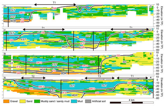
Figure 3.
Lithological cross-sections. Black solid lines indicate the locations of stratotype cores. SB, sequence boundary; TS, transgressive surface; IFS, initial flooding surface; MFS, maximum flooding surface; SH, Shimosa Group; BDR, braided river system; MDR, meandering river system; EST, estuary system; SPT, spit system; DLT, delta system; T1, T2, and T3, buried terraces.
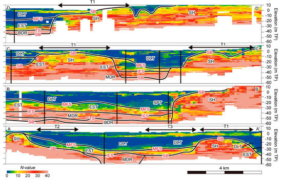
Figure 4.
N-value cross-sections. Black solid lines indicate the locations of stratotype cores. SB, sequence boundary; TS, transgressive surface; IFS, initial flooding surface; MFS, maximum flooding surface; SH, Shimosa Group; BDR, braided river system; MDR, meandering river system; EST, estuary system; SPT, spit system; DLT, delta system; T1, T2, and T3, buried terraces.
4.1. Section AA′
Section AA′ extends from the Musashino Upland in the west to the Edo River mouth in the east (Figure 2). The Paleo-Tokyo River Valley is in the center of this section, and buried terraces are located on both sides of the valley. The lithology below the buried terraces consists of laterally continuous sand and mud beds with relatively high N-values (>20). In contrast, the lithology above the buried terraces consists of laterally discontinuous sand and mud beds with relatively low N-values (<20) (Figure 3 and Figure 4). The former lithology is characteristic of the Shimosa Group, whereas the latter is characteristic of the post-LGM incised-valley fills [40]. Based on the comparison with stratotype cores obtained in the axis of the valley, the alternating sand and mud beds (N-value < 30) filling the 2-km-wide valley are interpreted as having been deposited by a meandering river system, the sand and mud beds (N-value = 5–20) extending widely above the buried terraces are interpreted as an estuary system, and the sand and mud beds (N-value = 0–10) distributed widely above the estuary system are interpreted as a delta system [20]. Gravel beds of the braided river system are presumably distributed beneath the meandering river system (Figure 3 and Figure 4). Where the meandering river system fills the narrow valley, the ground is relatively stiff, whereas ground composed of the delta system, which consists mainly of mud, is very soft (N-value = 0). The N-value of the estuary (delta) system decreases (increases) upward, which suggests the fining-upward (coarsening-upward) trend of the lithological successions. The buried terraces at average heights of −10 m TP and −45 m TP on the east side of the valley are, respectively, called the T1 and T3 surfaces in this study, and the buried terrace at an average height of −35 m TP on the west side of the valley is called the T2 surface (Figure 3 and Figure 4). Details of these surfaces are explained in the next section. The T1 surface overlies the Shimosa Group, and the T2 and T3 surfaces overlie the pre-LGM buried terrace gravel beds (BT).
4.2. Section BB′
Section BB′ extends from the Musashino Upland in the west to the Shimosa Upland in the east (Figure 2). On the west side of this section, the Ara and Naka River valleys merge to form the Paleo-Tokyo River Valley, whereas the east side is dominated by the Shimosa Group, which forms the Shimosa Upland. The Shimosa Group consists of laterally continuous sand and mud beds with relatively high N-values (>20), as in section AA′ (Figure 3 and Figure 4). The post-LGM incised-valley fills consist in stratigraphical order of gravel beds (N-value >40) of the braided river system, alternating sand and mud beds (N-value = 10–20) of the meandering river system, sand and mud beds (N-value = 5–20) of the estuary system, and sand and mud beds (N-value = 0–10) of the delta system. Sand and mud beds (N-value = 5–10) at the western margin of the Shimosa Upland are regarded as a spit system (Figure 3 and Figure 4) [20].
4.3. Section CC′
Section CC′ extends from the Omiya Upland in the west to the Shimosa Upland in the east (Figure 2). The Naka River Valley is in the east central part of this section, and the Ayase River Valley, a branch of the Naka River Valley, is on the west side. The T1 buried terraces are distributed both east of the Naka River Valley and between the Naka and Ayase River valleys. In this section, the Shimosa Group consists of laterally continuous sand and mud beds. However, the N-values of the uppermost mud of the Shimosa Group between the Naka and Ayase River valleys are lower (5–20) than typical N-values of the Shimosa Group (Figure 3 and Figure 4). In the Naka River Valley, gravel beds of the braided river system are absent. The post-LGM incised-valley fills consist in stratigraphical order of alternating sand and mud beds (N-value = 10–20) of the meandering river system, sand and mud beds (N-value = 5–20) of the estuary system, and sand and mud beds (N-value = 0–10) of the delta system. In the Naka River Valley, thick estuary system deposits are accreted on the western slope of the incised valley, but they are thinly distributed in the valley axis, because tidal currents occurred in the elongated bay where the estuary system developed (Figure 3 and Figure 4) [20]. In the Ayase River Valley, the post-LGM incised-valley fill consists of a thick mud bed with a very low N-value of 0–1. In the stratotype core from the Ayase River Valley, the estuary/delta system boundary (MFS) is at −10 m TP (Figure 3 and Figure 4) [20].
4.4. Section DD′
Section DD′ extends from the Omiya Upland in the west to the Shimosa Upland in the east. The Naka River Valley is at the west side of this section, and the Shimosa Group, constituting the Shimosa Upland, is on the east side. Here, the Shimosa Group consists of sand and mud beds with N-values > 10, and it is unusual in that the N-value of the sand beds is smaller than that of the mud beds (Figure 3 and Figure 4). The post-LGM incised-valley fill in the Naka River Valley consists in stratigraphical order of gravel beds of the braided river system (N-value >40), sand and mud beds of the estuary system (N-value = 0–10), and sand and mud beds of the delta system (N-value = 0–10). The MFS is within a mud bed with an N-value of around 0, as in the Ayase River Valley (Figure 3 and Figure 4; section CC′). The buried terrace at −10 m TP is correlated to the T1 surface on the basis of its depth and the absence of the pre-LGM buried terrace gravel beds.
5. Incised Valleys, Buried Terraces, and Soft Mud
Figure 5 shows the distribution of the incised valleys that formed until the LGM beneath the Tokyo and Nakagawa lowlands. The Naka and Ara River valleys converge in the northern part of the Tokyo Lowland to form the Paleo-Tokyo River Valley. Furthermore, small branches of the incised valleys can be observed: the Gyotoku and Saka River valleys dissect the Shimosa Upland; the Ayase River Valley dissects the Omiya Upland; and the Paleo-Kanda River Valley dissects the Musashino Upland. The Paleo-Tokyo River Valley is the deepest valley in the study area; its floor is at −77 m TP in the area adjacent to the present Ara River mouth.
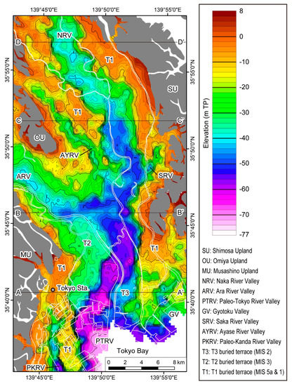
Figure 5.
Depth distribution of the base of the post-LGM incised-valley fills. The contour interval is 2 m.
The LGM incised valleys are bordered by the T1, T2, and T3 buried terrace surfaces.
The T1 surface occurs at a height above −10 m TP, and its depth is shallower at more inland locations (Figure 5). The T1 terrace deposits are finer grained than the other terrace sediments and lack gravel beds. In the southern Tokyo Lowland, a buried terrace surface can be correlated to the T1 surface, which is overlain by the Hk-TP tephra (MIS 4) [41]. This surface was previously regarded as an abrasion platform formed during the middle Holocene sea-level highstand [30,40,42], but it is now regarded as the MIS 5a Musashino Terrace [43]. The terrace surface is slightly eroded by wave action during the middle Holocene sea-level highstand, but only the loam bed on the T1 surface was eroded away at that time, exposing the original topographic surface formed during MIS 5a [26,39,44]. In this study, we consider that most of the T1 terrace surface was formed during MIS 5a, and that it consists in part of an abrasion platform formed during the middle Holocene highstand. Wave energy was presumably high in the southern Tokyo Lowland, which was near the center of Tokyo Bay. The T1 terrace deposits lack gravel beds because the eustatic sea level was around 20 m below the present sea level during MIS 5a [45], and the river gradients were relatively low.
The T2 terrace surface occurs at a height above −35 m TP, and at shallower depths at more inland locations (Figure 5). Gravel beds underlie the T2 surface. In the western Tokyo Lowland, the T2 surface is covered by a loam bed containing the Aira Tn (AT) tephra that was dated to 30.0 ka [46]. Therefore, this surface can be correlated with the MIS 3 Tachikawa Terrace. The eustatic sea level during MIS 3 was 80 m below the present level [45]. Thus, the river gradients were relatively steep leading to the formation of the buried terrace gravel beds.
The T3 surface occurs at a height of around −45 m TP only in the vicinity of the present Ara River mouth (Figure 2 and Figure 5). The T3 terrace deposits contain gravel beds. The T3 surface occurs at a height below the T2 surface, which is covered by the AT tephra, and above the floor of the LGM incised valley. Therefore, it might have formed during the sea-level plateau in the first half the LGM (30.0–21.5 ka) [47,48]. However, the age of T3 and its distribution further upstream must be clarified in future.
Figure 6 is an isopach map of soft mud with an N-value of 0 and 1 (“N1 mud”) in the Tokyo and Nakagawa lowlands. The N1 mud is thin along the western margin of the Shimosa Upland and up to 20 m thick close to the axes of the Naka and Ayase River valleys. The N1 mud is thin along the western margin of the Shimosa Upland because of the occurrence of the sandy beds of the spit system instead of mud beds of the delta system (Figure 3 and Figure 4) [20]. It is also relatively thin in the Ara River Valley compared to the Naka River Valley because the Tone River, which flowed along the course of the present Ara River until 5 ka, deposited coarse sediment. As a result of the postglacial sea-level rise, a bay environment developed after 10 ka in the Naka and Ayase River valleys. The Naka and Ayase River valleys were sediment starved, and an inner bay environment with low wave and tidal energies existed until the Tone River shifted its course from the present Ara River to the Naka River at 5 ka [20]. This allowed the deposition of the thick N1 mud in the Naka and Ayase River valleys.
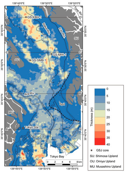
Figure 6.
Isopach map of the N1 mud.
6. Relation between the Thicknesses of the Post-LGM Incised-Valley Fills and N1 Mud and Earthquake Damage
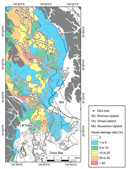
Figure 7 shows the distribution of wooden house damage ratios following the 1923 Taisho Kanto Earthquake in the Tokyo and Nakagawa lowlands. Kaizuka and Matsuda [11] calculated the house damage ratio in each village as follows: house damage ratio = collapse ratio of wooden houses + half-collapse ratio of wooden houses ÷ 2. The construction quality of the wooden houses was almost the same during the 1920s [11,13]. Comparison of the damage ratio distribution (Figure 7) with the thicknesses of the post-LGM incised-valley fills (Figure 8) and N1 mud (Figure 9) indicates that the house damage ratio corresponds better to the thickness of the N1 mud rather than to that of the post-LGM incised-valley fills. In the inner portions of the Ayase and Naka River valleys, the N1 mud is up to 20 m thick, and the house damage ratio is over 20% (Figure 5 and Figure 9). In contrast, the house damage ratio was 0% along the western margin of the Shimosa Upland where the spit system is distributed and N1 mud is absent (Figure 9). The spit system corresponds to relatively stiff sandy ground. The fact that the post-LGM incised-valley fills thicken to more than 50 m in the area where the spit system is distributed indicates that the house damage ratio was not necessarily high in areas where the post-LGM incised-valley fills are thick (Figure 8). The house damage ratio was also relatively high along the eastern margin of the Omiya Upland, where the post-LGM incised-valley fills are thinner than 10 m (Figure 8). In this area, the high damage ratio might be related to the distribution of soft mud of the MIS 5e lower Kioroshi Formation. The lower Kioroshi Formation occasionally contains soft mud with an N-value of ca. 5 [25]. In this study, we ignored the relationship between the house damage ratio and liquefaction.
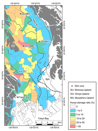
Figure 7.
Distribution of the wooden house damage ratio following the 1923 Taisho Kanto Earthquake. This map is a trimmed version of a previously published larger map of the house damage ratio distribution in the entire Kanto Plain [11].
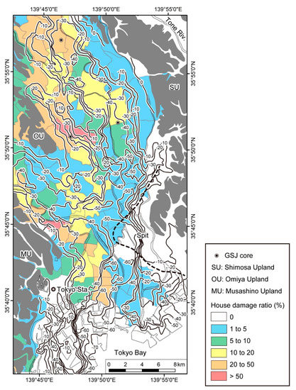
Plots of the house damage ratio against the thicknesses of the post-LGM incised-valley fills and the N1 mud (Figure 10) show that the house damage ratio was highest in areas where the post-LGM incised-valley fill is 30 m thick and the N1 mud is 20 m thick. The average S-wave velocity is 150 m/s in the post-LGM incised-valley fills and 100 m/s in the N1 mud (Figure 11). The natural resonance period T of each sediment can be calculated as follows:
where H is thickness and Vs is S-wave velocity [13]. Therefore, the natural period of both the 30-m-thick post-LGM incised-valley fill and the 20-m-thick N1 mud is 0.8 s. This value roughly matches the natural resonance period of wooden houses (ca. 1 s). Therefore, based on this simplified one-dimensional model [13], resonance would have caused strong shaking and vibration during the earthquake. The majority of wooden houses collapsed due to this resonance [12,13,14,15]. According to Kanai [12], Ogawa and Nakayama [14], and Kuritsuka and Ogawa [15], where the post-LGM incised-valley fills are thicker or thinner than 30 m, and the Holocene marine mud, which corresponds to the N1 mud, is thicker or thinner than 20 m, the house damage ratio decreases because the natural period of the sediments deviates from 1 s (Figure 10).
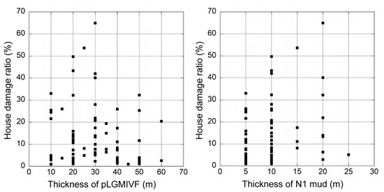
Figure 10.
Plots of the house damage ratio following the 1923 Taisho Kanto Earthquake against the thickness of the post-LGM incised-valley fills (pLGMIVF) and N1 mud. The thickness values are the 5-m-interval averaged values in the extent of each village in the Tokyo and Nakagawa lowlands.
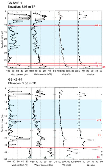
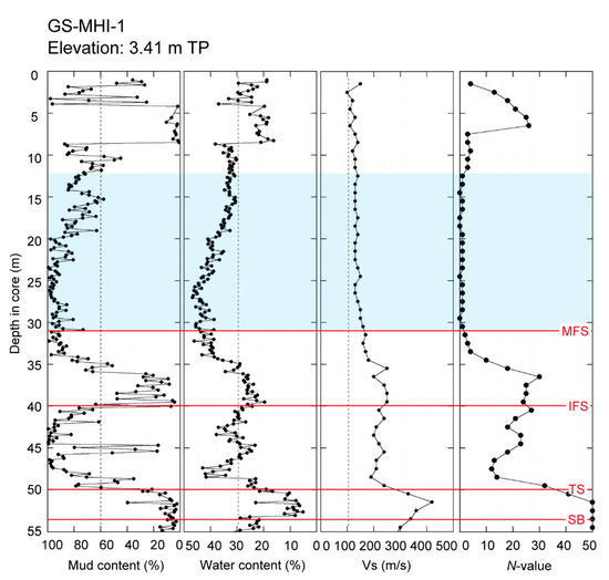
Figure 11.
Physical properties of the N1 mud in the stratotype cores. Blue shadings indicate the intervals of the N1 mud. SB, sequence boundary; TS, transgressive surface; IFS, initial flooding surface; MFS, maximum flooding surface. The SB corresponds to the unconformity between the Shimosa Group and the post-LGM incised-valley fills. The TS, IFS, and MFS correspond to the braided/meandering river, meandering river/estuary, and estuary/delta system boundaries, respectively.
In the Nakagawa Lowland, the GS-SMB-1 stratotype core was obtained from the region where the house damage ratio was over 50%, GS-KBH-1 was obtained where the house damage ratio was 20–50%, and GS-MHI-1 was obtained where the house damage ratio was 10–20% (Figure 7) [20]. The N1 muds are 28 m, 21 m, and 19 m thick in cores GS-SMB-1, GS-KBH-1, and GS-MHI-1, respectively (Figure 11). The depositional age of the N1 mud is 10–3 ka [20]. In these cores, the N1 mud consists of estuarine and deltaic bay muds with a mud content of more than 60% and a water content of more than 30%, and around the MFS, the mud content is as high as 100% and the water content is as high as 50% (Figure 11). This extremely soft mud is at it thickest (5 m) in core GS-KBH-1. However, the house damage ratio at the GS-KBH-1 site was not as high as that at the GS-SMB-1 site. The minimum S-wave velocity of the post-LGM incised-valley fills is around 80 m/s (Figure 11). With this S-wave velocity, the sediments must be thicker than 20 m for the natural resonance period to be 1 s. When the S-wave velocity is higher than 80 m/s, the sediments must be thicker to obtain a natural resonance period of 1 s. It is widely known that the near-surface geology and earthquake damage are strongly related (e.g., [17,18]). However, we argue that the thickness of soft sediments is more important than the stiffness of the sediments (e.g., the presence of extremely soft mud) for predicting earthquake damage in the alluvial lowlands where post-LGM incised-valley fills occur.
7. Conclusions
In this study, we mapped isopachs of the post-LGM incised-valley fills and N1 mud beneath the Tokyo and Nakagawa lowlands by using 13,000 borehole logs. The N1 mud consists of Holocene muds of the estuary and delta systems that were deposited in an inner bay environment where the wave and tidal energy was low. The N1 mud is not always thick in areas where the post-LGM incised-valley fills are thick. Comparison of the thicknesses of the post-LGM incised-valley fills and the N1 mud with the wooden house damage ratio following the 1923 Taisho Kanto Earthquake suggests that the house damage ratio related better to the thickness of the N1 mud rather than to that of the post-LGM incised-valley fills. Furthermore, the house damage ratio was highest where the post-LGM incised-valley fill thickness is 30 m and the N1 mud thickness is 20 m because in those areas, the natural resonance period of the sediments corresponded to that of the wooden houses (ca. 1 s). Where the post-LGM incised-valley fills and the N1 mud are thicker or thinner than these values, the house damage ratio was smaller because the natural period of the sediments deviated from 1 s. Previously, knowledge of the resonance period of the post-LGM incised-valley fills in relation to the house damage ratio was based mainly on data from the Tokyo Lowland. However, by incorporating data from the Nakagawa Lowland, we showed that the thickness of the N1 mud is especially important for predicting earthquake damage in alluvial lowlands where post-LGM incised-valley fills occur in the subsurface.
Author Contributions
S.T. analyzed the datasets and wrote the paper. Y.I. created the voxel model and illustrated the geological cross-sections. T.N. analyzed the stratotype cores. J.S. and F.S.B. were involved in discussion and text editing. This work was designed and performed based on discussions among all the authors. All authors have read and agreed to the published version of the manuscript.
Funding
This research was financially supported by the National Institute of Advanced Industrial Science and Technology (AIST) research program “Geological and active faults survey project in coastal areas of Japan”.
Institutional Review Board Statement
Not applicable.
Informed Consent Statement
Not applicable.
Data Availability Statement
Not applicable.
Acknowledgments
We are thankful for the valuable comments from three anonymous reviewers which improved the manuscript.
Conflicts of Interest
The authors declare no conflict of interest.
References
- Wikipedia. Tokyo. Available online: https://en.wikipedia.org/wiki/Tokyo (accessed on 6 May 2021).
- Hirata, N. Tokyo Metropolitan Earthquake; Iwanami Shoten: Tokyo, Japan, 2016; p. 191. [Google Scholar]
- Shishikura, M. History of the paleo-earthquakes along the Sagami Trough, central Japan: Review of coastal paleoseismological studies in the Kanto region. Episodes 2014, 37, 246–257. [Google Scholar] [CrossRef] [Green Version]
- Komori, J.; Shishikura, M.; Ando, R.; Yokoyama, Y.; Miyairi, Y. History of the great Kanto earthquakes inferred from the ages of Holocene marine terraces revealed by a comprehensive drilling survey. Earth Planet. Sci. Lett. 2017, 471, 74–84. [Google Scholar] [CrossRef]
- Matsuzawa, T. Report on distribution of earthquake damage based on wooden buildings. In Report of the Imperial Earthquake Investigation Committee, No. 100 (A); Iwanami Shoten: Tokyo, Japan, 1925; pp. 163–260. [Google Scholar]
- Building Department, Reconstruction Bureau. Report on Geological Investigation in Tokyo and Yokohama; Building Department, Reconstruction Bureau: Tokyo, Japan, 1929; 144p.
- Miyabe, N. On the vertical earth movements in Kwanto districts. Bull. Earthq. Res. Inst. Univ. Tokyo 1931, 9, 1–21. [Google Scholar] [CrossRef]
- Wikipedia. 1923 Great Kanto Earthquake. Available online: https://en.wikipedia.org/wiki/1923_Great_Kanto_earthquake (accessed on 10 June 2021).
- Kawazumi, H. On the earthquake-stricken areas and their underground formation in Tokyo, appendix-underground formation of Osaka observed through boring tests. J. Archit. Build. Sci. 1951, 66, 8–15. [Google Scholar]
- Ohsaki, Y. Earthquake damage of wooden buildings and depth of alluvial deposits. Trans. Archit. Inst. Jpn. 1962, 72, 29–32. [Google Scholar] [CrossRef]
- Kaizuka, S.; Matsuda, I. Active Tectonics and Geomorphic Division of the Tokyo Metropolitan Area and Damage Ratio due to the Kanto Earthquake of 1923. 1:200,000; Naigai Chizu: Tokyo, Japan, 1982. [Google Scholar]
- Kanai, K. On the Damage to Building by the Kawanto Earthquake. In Publications for the 50th Anniversary of the Great Kanto Earthquake, 1923; Earthquake Research Institute, the University of Tokyo: Tokyo, Japan, 1973; pp. 51–55. [Google Scholar]
- Ohsaki, Y. Earthquake and Architecture; Iwanami Shoten: Tokyo, Japan, 1983; 105p. [Google Scholar]
- Ogawa, Y.; Nakayama, T. Review of Experiential Relation between Building Damage Ratio and Thickness of Alluvial Deposits during the 1923 Kanto Earthquake; Annual Report of Civil Engineering Support and Training Center, Tokyo Metropolitan Government: Tokyo, Japan, 2009; pp. 33–42.
- Kuritsuka, K.; Ogawa, Y. Estimation of Predominant Periods in Tokyo Lowland on the Bases of Compensated Seismograph during the 1923 Kanto Earthquake; Annual Report of Civil Engineering Support and Training Center, Tokyo Metropolitan Government: Tokyo, Japan, 2014; pp. 15–20.
- Sekiguchi, H.; Yoshida, K.; Kimura, K.; Hanashima, Y. Ground motion response of the subsurface structure of the Nakagawa lowland. Misc. Map Ser. Geol. Surv. Jpn. 2014, 40, 136–177. [Google Scholar]
- Guidoboni, E.; Mariotti, D.; Giammarinaro, M.S.; Rovelli, A. Identification of amplified damage zones in Palermo, Sicily (Italy), during the earthquakes of the last three centuries. Bull. Seismol. Soc. Am. 2003, 93, 1649–1669. [Google Scholar] [CrossRef]
- Maresca, R.; Nardone, L.; Gizzi, F.T.; Potenza, M.R. Ambient noise HVSR measurements in the Avellino historical centre and surrounding area (southern Italy). Correlation with surface geology and damage caused by the 1980 Irpinia-Basilicata earthquake. Measurement 2018, 130, 211–222. [Google Scholar] [CrossRef]
- Ishihara, Y.; Miyazaki, Y.; Eto, C.; Fukuoka, S.; Kimura, K. Shallow subsurface three-dimensional geological model using borehole logs in Tokyo Bay area, central Japan. J. Geol. Soc. Jpn. 2013, 119, 554–566. [Google Scholar] [CrossRef] [Green Version]
- Tanabe, S.; Nakanishi, T.; Ishihara, Y.; Nakashima, R. Millennial-scale stratigraphy of a tide-dominated incised valley during the last 14 kyr: Spatial and quantitative reconstruction in the Tokyo Lowland, central Japan. Sedimentology 2015, 62, 1837–1872. [Google Scholar] [CrossRef]
- Tanabe, S.; Nakanishi, T.; Kimura, K.; Hachinohe, S.; Nakayama, T. Basal topography of the Alluvium under the northern area of the Tokyo Lowland and Nakagawa Lowland, central Japan. Bull. Geol. Surv. Jpn. 2008, 59, 497–508. [Google Scholar] [CrossRef] [Green Version]
- Tanabe, S.; Ishihara, Y. Incised-valley topography formed into the Last Glacial Maximum beneath the southern area of the Tokyo Lowland, central Japan. Bull. Geol. Surv. Jpn. 2020, 71, 201–213. [Google Scholar] [CrossRef]
- Stafleu, J.; Maljers, D.; Busschers, F.S.; Schokker, J.; Gunnink, J.L.; Dambrink, R.M. Chapter 11: Models created as 3-D cellular voxel arrays. In Applied Multidimensional Geological Modeling; Turner, A.K., Kessler, H., Van der Meulen, M.J., Eds.; Wiley-Blackwell: Hoboken, NJ, USA, 2021; pp. 247–271. [Google Scholar]
- Okuno, J.; Nakada, M.; Ishii, M.; Miura, H. Vertical tectonic crustal movements along the Japanese coastlines inferred from late Quaternary and recent relative sea-level changes. Quat. Sci. Rev. 2014, 91, 42–61. [Google Scholar] [CrossRef]
- Nakazawa, T.; Endo, H. Geology of the Omiya District; Quadrangle Series, 1:50,000; Geological Survey of Japan: Tsukuba, Japan, 2002; 41p. [Google Scholar]
- Ishihara, T.; Sugai, T. Eustatic and regional tectonic controls on late Pleistocene paleovalley morphology in the central Kanto Plain, Japan. Quat. Int. 2017, 456, 69–84. [Google Scholar] [CrossRef]
- Okuma, T. Influences of the river modification and the eruption of the Asama volcano at the beginning of the early modern period. Urban Kubota 1981, 19, 18–31. [Google Scholar]
- Milliman, J.D.; Farnsworth, K.L. River Discharge to the Coastal Ocean: A Global Synthesis; Cambridge University Press: Cambridge, UK, 2011; 384p. [Google Scholar]
- Chujo, J. On the Paleo-Tokyo River: Prospected by the sonic prospecting. Earth Sci. 1962, 59, 30–39. [Google Scholar]
- Kaizuka, S.; Naruse, Y.; Matsuda, I. Recent formations and their topography in and around Tokyo Bay, central Japan. Quat. Res. 1977, 8, 32–50. [Google Scholar] [CrossRef]
- Endo, K.; Kosugi, M.; Hishida, R. Holocene and latest Pleistocene deposits and their basal topography in the Kanto Plain, central Japan. Proc. Inst. Nat. Sci. Nihon Univ. 1988, 23, 37–48. [Google Scholar]
- van Wagoner, J.C.; Posamentier, H.W.; Mitchum, R.M.; Vail, P.R.; Sarg, J.F.; Louit, T.S.; Hardenbol, J. An overview of the fundamentals of sequence stratigraphy and key definitions. SEPM Spec. Publ. 1988, 42, 39–45. [Google Scholar]
- Zaitlin, B.A.; Dalrymple, R.W.; Boyd, R. The stratigraphic organization of incised-valley systems: Origin and sedimentary sequences. SEPM Spec. Publ. 1994, 51, 45–60. [Google Scholar]
- Tanabe, S. Stepwise accelerations in the rate of sea-level rise in the area north of Tokyo Bay during the Early Holocene. Quat. Sci. Rev. 2020, 248, 106575. [Google Scholar] [CrossRef]
- Geological Research Group of the Central Kanto Plain. Subsurface Geology in the Central Kanto Plain; The Association of the Geological Collaboration in Japan: Tokyo, Japan, 1994; 180p. [Google Scholar]
- Ishihara, T.; Sugai, T.; Hachinohe, S. Fluvial response to sea-level changes since the latest Pleistocene in the near-coastal lowland, central Kanto Plain, Japan. Geomorphology 2012, 147–148, 49–60. [Google Scholar] [CrossRef]
- Ministry of Land, Infrastructure, Transport and Tourism. A Guidebook for Submission of Electric Formatted Report on Geology and Soil Investigation. Available online: http://www.cals-ed.go.jp/mg/wp-content/uploads/boring71.pdf (accessed on 27 August 2019).
- Editorial Committee of “Story of N-value”. Story of N-Value; Riko Tosho: Tokyo, Japan, 1998; 188p. [Google Scholar]
- Tanabe, S.; Ishihara, Y. Formation of undulating topography and gravel beds at the bases of incised valleys: Last Glacial Maximum examples beneath the lowlands facing Tokyo Bay. Prog. Earth Planet Sci. 2021, 8, 20. [Google Scholar] [CrossRef]
- Matsuda, I. Distribution of the recent deposits and buried landforms in the Kanto Lowland, central Japan. Geogr. Rep. Tokyo Metrop. Univ. 1974, 9, 1–36. [Google Scholar]
- Machida, H.; Arai, F. Atlas of Tephra in and around Japan; University of Tokyo Press: Tokyo, Japan, 2003; 336p. [Google Scholar]
- Bureau of Port and Harbor, Tokyo Metropolitan Government. Subsurface Geological Map of Tokyo Port, New Edition; Bureau of Port and Harbor, Tokyo Metropolitan Government: Tokyo, Japan, 2001; 89p.
- Port of Tokyo Geological Research Group. Stratigraphy of the Port of Tokyo, Japan. Monogr. Assoc. Geol. Collab. Jpn. 2000, 47, 10–22. [Google Scholar]
- Tanabe, S.; Ishihara, T.; Komatsubara, T. Undulating topography at the base of the Alluvium: Preliminary interpretation on the formation. Bull. Geol. Surv. Jpn. 2014, 65, 45–55. [Google Scholar] [CrossRef] [Green Version]
- Siddall, M.; Rohling, E.J.; Almogi-Labin, A.; Hemleben, C.; Meischner, D.; Schmelzer, I.; Smeed, D.A. Sea-level fluctuations during the last glacial cycle. Nature 2003, 423, 853–858. [Google Scholar] [CrossRef]
- Smith, V.C.; Staff, R.A.; Blockley, S.P.E.; Bronk Ramsey, C.; Nakagawa, T.; Mark, D.F.; Takemura, K.; Danhara, T.; Suigetsu 2006 Project Members. Identification and correlation of visible tephras in the Lake Suigetsu SG06 sedimentary archive, Japan: Chronostratigraphic markers for synchronising of east Asian/west Pacific palaeoclimatic records across the last 150 ka. Quat. Sci. Rev. 2013, 67, 121–137. [Google Scholar] [CrossRef]
- Yokoyama, Y.; Esat, T.M.; Thompson, W.G.; Thomas, A.L.; Webster, J.M.; Miyairi, Y.; Sawada, C.; Aze, T.; Matsuzaki, H.; Okuno, J.; et al. Rapid glaciation and a two-step sea level plunge into the Last Glacial Maximum. Nature 2018, 559, 603–607. [Google Scholar] [CrossRef] [PubMed]
- Ishiwa, T.; Yokoyama, Y.; Okuno, J.; Obrochta, S.; Uehara, K.; Ikehara, M.; Miyairi, Y. A sea-level plateau preceding the Marine Isotope Stage 2 minima revealed by Australian sediments. Sci. Rep. 2019, 9, 6449. [Google Scholar] [CrossRef]
Publisher’s Note: MDPI stays neutral with regard to jurisdictional claims in published maps and institutional affiliations. |
© 2021 by the authors. Licensee MDPI, Basel, Switzerland. This article is an open access article distributed under the terms and conditions of the Creative Commons Attribution (CC BY) license (https://creativecommons.org/licenses/by/4.0/).