Article

Experimental and Numerical Assessment of Seismic Retrofit Solutions for Stone Masonry Buildings

1
Department of Civil Engineering and Architecture (DICAr), University of Pavia, Via Ferrata 3, 27100 Pavia, Italy
2
European Centre for Training and Research in Earthquake Engineering (EUCENTRE), Via Ferrata 1, 27100 Pavia, Italy
*
Author to whom correspondence should be addressed.
Geosciences 2021, 11(6), 230; https://doi.org/10.3390/geosciences11060230
Submission received: 14 April 2021 / Revised: 24 May 2021 / Accepted: 25 May 2021 / Published: 27 May 2021

Abstract

:
This paper presents an experimental and numerical study on different retrofit solutions for stone masonry buildings with timber diaphragms in earthquake-prone regions, aiming at enhancing wall-to-diaphragm connections, diaphragms’ stiffness, and masonry properties. The experimental results of incremental dynamic shake-table tests on three full-scale two-story buildings, complemented by material and component characterization tests, are initially summarized. The first building specimen was unstrengthened. The second one was retrofitted at the floor and roof levels with improved wall-to-diaphragm connections and a moderate increase in diaphragm stiffness. Connections were also improved in the third specimen together with a significant enhancement of diaphragm stiffness. The calibration of two numerical models, versus the experimental response of the retrofitted building specimens, is then presented. The models were further modified and reanalyzed to assess the effects of masonry mechanical upgrades, which could be achieved in practice through deep joint repointing or various types of jacketing. These solutions were simulated by applying correction coefficients to the masonry mechanical properties, as suggested by the Italian building code. The effectiveness of the experimentally implemented and numerically simulated interventions are discussed in terms of strength enhancement and failure modes.

1. Introduction

Masonry constitutes most of the building stock worldwide, especially concerning heritage construction systems. Among the different masonry types, natural stone masonry is rather common in mountain and rural areas as well as in historical centers. As a material, stone masonry is typically characterized by high heterogeneity and anisotropy combined with low tensile and shear strength, often due to the poor mechanical properties of its constitutive materials. Moreover, historical masonry buildings have been usually conceived to only carry vertical loads, without any consideration for lateral resistance, and have been subjected to a continuous process of modification over the ages. These factors result in the high vulnerability of ordinary and monumental stone masonry buildings, as observed for example after recent major earthquakes in Italy [1,2,3,4,5,6].
Among other parameters affecting the seismic vulnerability of masonry structures, the degree of connection between intersecting walls and between walls and floors play a significant role, as well as the in-plane stiffness of floor diaphragms [7,8,9]. In fact, poor connections may lead to the development of local out-of-plane overturning mechanisms of individual walls, even under low or moderate shaking intensity [10,11,12]. On the other hand, excessively flexible floor diaphragms may not allow an efficient distribution of the horizontal inertia forces among different walls, and may not be effective at preventing local mechanisms.
Consequently, enhancing the in-plane response of individual masonry walls can influence the building seismic performance only if local out-of-plane mechanisms are restrained and sufficient stiffness is provided to the diaphragms, enabling a box-type global behavior of the structure [13,14,15]. At the same time, however, connection strengthening and diaphragm stiffening interventions can be implemented only if the masonry walls can resist the forces transferred locally; this often requires improving the masonry properties, to avoid some detrimental effects observed over the past three decades [16,17,18,19,20]. In particular, masonry disgregation and leaf delamination typical of poor bond and constituents should be preliminarily addressed by material enhancements.
In light of these considerations, three main strategies interact with each other in the retrofit of a stone masonry building [21,22]:
  • improvement of connections;
  • stiffening of floor diaphragms;
  • enhancement of masonry properties.
The first group encompasses interventions such as anchor rods [23,24,25,26], tie-rods [26,27,28,29,30], and ring beams [31,32,33,34]. Solutions for increasing the diaphragm in-plane shear stiffness include additional layers of timber planks or panels or cast-in-place reinforced concrete (RC) slabs, properly connected to the existing joists [23,35,36,37]. Several techniques can be adopted to improve masonry mechanical properties [38,39], depending on the desired effect and compatibility issues; this study focuses on the structural effectiveness of deep joint repointing [40,41] and jacketing with reinforced plasters and composite materials [42,43,44,45,46,47,48,49,50].
A comprehensive experimental campaign on the seismic performance of double-leaf stone masonry was undertaken at the EUCENTRE Foundation and at the University of Pavia, Italy. The project was centered on the uniaxial incremental dynamic shake-table tests of three full-scale, two-story buildings, representative of various levels of strengthening interventions on the same original structure [51,52,53]. The testing program included material characterization tests [54] and in-plane cyclic tests of masonry piers [55] and spandrels [56].
More specifically, the first building specimen was initially tested in an unretrofitted configuration, and tie-rods were tensioned only after the activation of a local overturning mechanism. The second specimen was retrofitted by improving its wall-to-diaphragm connections with steel and reinforced masonry (RM) ring beams at the first floor and roof level, respectively; diaphragm stiffness was only slightly increased by adding a layer of 45-degree oriented timber planks. Connections were also enhanced in the third specimen but they were associated with a significant increase in diaphragm stiffness; in this case, a lightweight RC slab was cast on the first-floor and connected to the timber joists and masonry walls, while additional plywood panels and an RC ring beam were provided to the roof diaphragm.
After summarizing the experimental work, this paper focuses on the numerical modeling of the two strengthened building specimens, to simulate the test results and to evaluate further seismic performance enhancements due to masonry mechanical improvements. An equivalent frame approach has been adopted, as implemented in the software TREMURI [57,58], with nonlinear macroelements for masonry piers and spandrels, linear elastic membranes for floor and roof diaphragms, and linear elastic elements for ring beams. Material properties have been calibrated against the results of material and component characterization tests. Nonlinear pushover analyses have been carried out on the building models, to capture the backbone curves obtained from the shake-table tests.
Strengthening interventions for the enhancement of the masonry material have then been assessed numerically by repeating the pushover analyses after the application of correction coefficients to the masonry mechanical properties, as suggested by the Italian building code [59,60], since these retrofit details could not be explicitly modeled through the chosen macroelement discretization. In particular, correction coefficients compatible with deep joint repointing or various types of reinforced plasters have been considered. The effectiveness of different retrofit approaches and combinations is finally discussed.

2. Experimental Program

The three building specimens tested in the experimental campaign are similar in terms of geometry and masonry characteristics. They differ, however, for the strengthening/stiffening interventions adopted. The following sections describe the masonry structure and the floor framing common to all three building specimens. Then, they provide details of the retrofit interventions adopted at the floor and roof levels of Building 2 [52] and Building 3 [53], while Building 1 [51] was tested in unstrengthened original configuration.

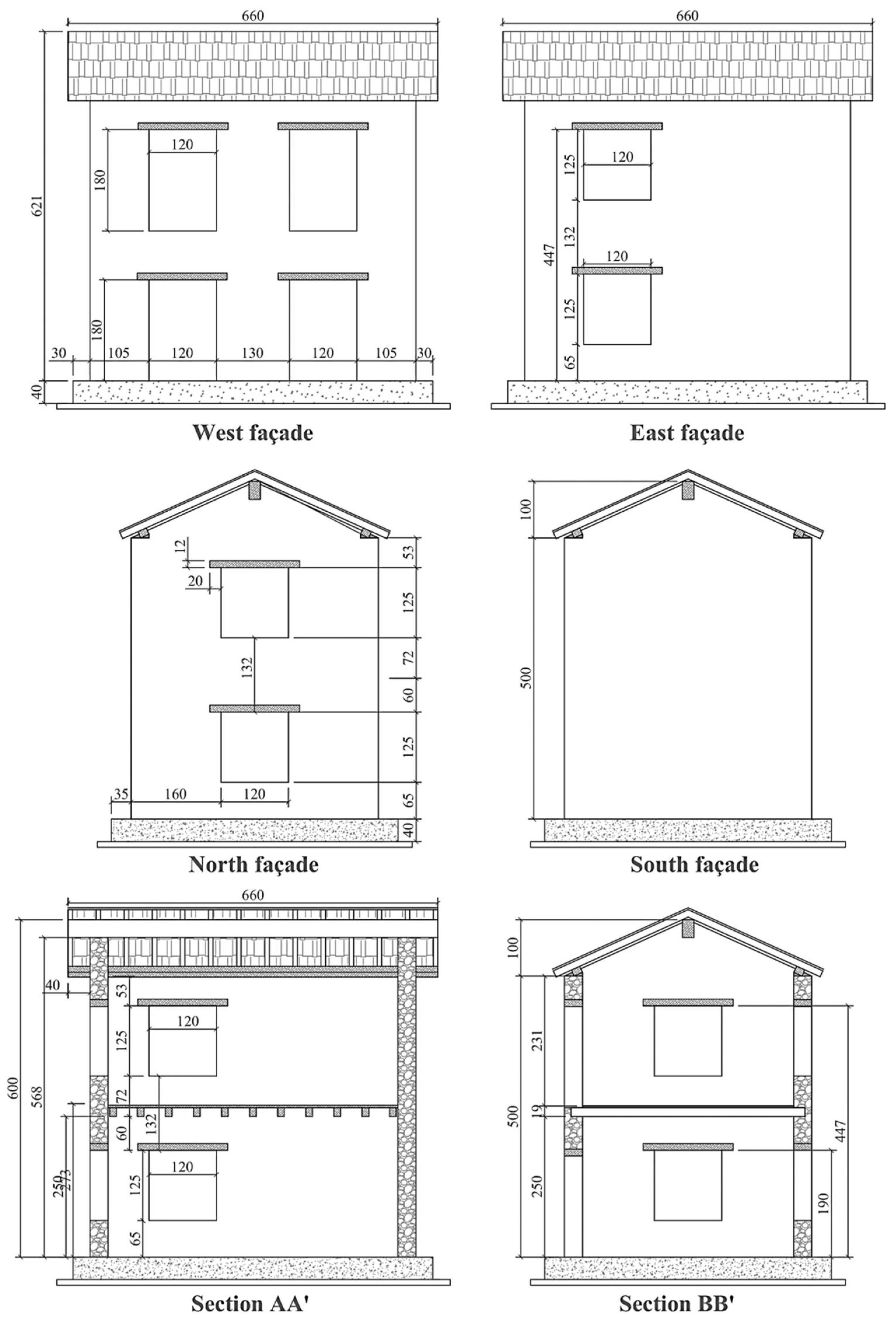
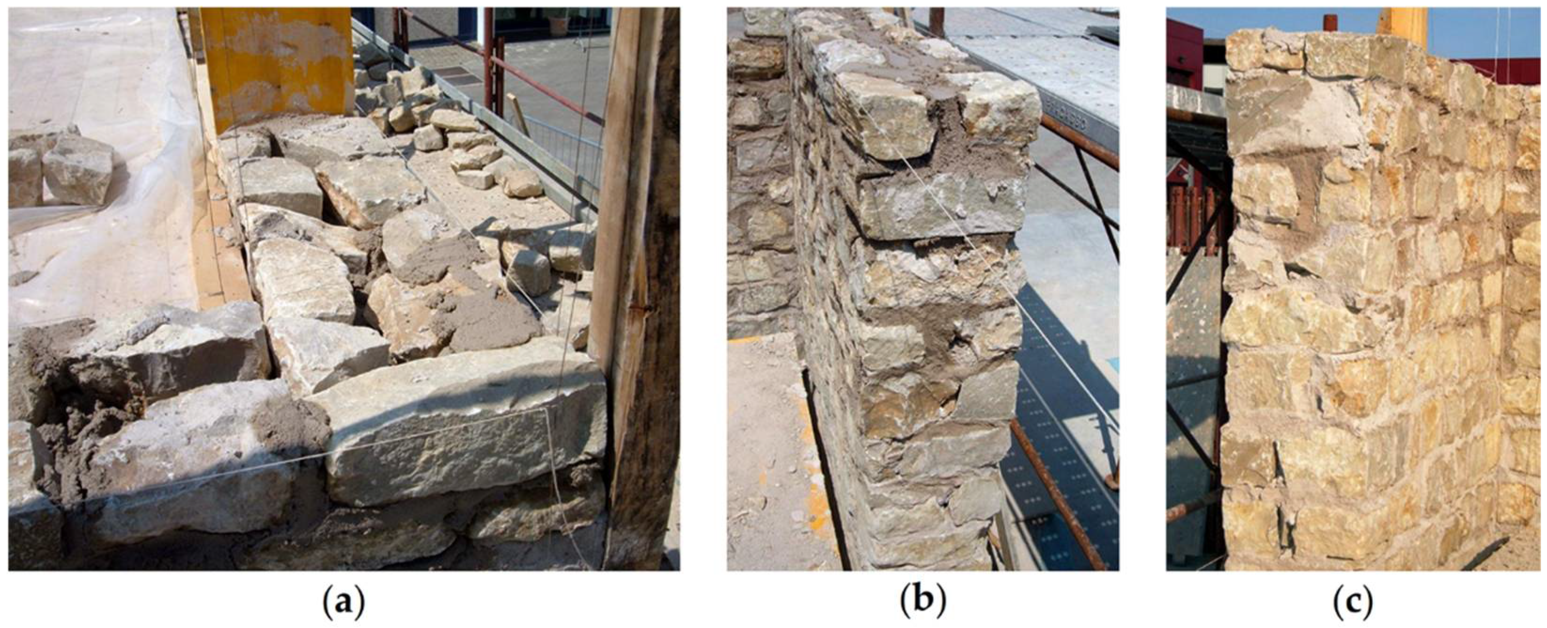
2.1. Masonry Structures

The reference geometry of the specimens simulates the characteristics of a common type of historical residential construction in Italy. The building was designed as a single-room structure with an external footprint of 5.8 × 4.4 m. It included two stories with pitched roof, as shown in Figure 1 and Figure 2. The longitudinal walls, namely the East and West façades, were oriented in the direction of the shaking table motion, while the North and South walls were perpendicular to it. In order to induce in-plan shear distortional or torsional effects under uniaxial shake-table motion, the building was characterized by an asymmetric distribution of openings on the longitudinal walls.
The structural walls consisted of double-leaf undressed stone masonry with overall nominal thickness of 32 cm, with some smaller stones mixed with mortar but no loose material to fill the irregular gaps between the leaves. Connection between intersecting walls was achieved by providing through stones alternatively in the internal or external leaf of the two walls at the corners (Figure 3a). Through stones were also located at opening edges (Figure 3b,c).

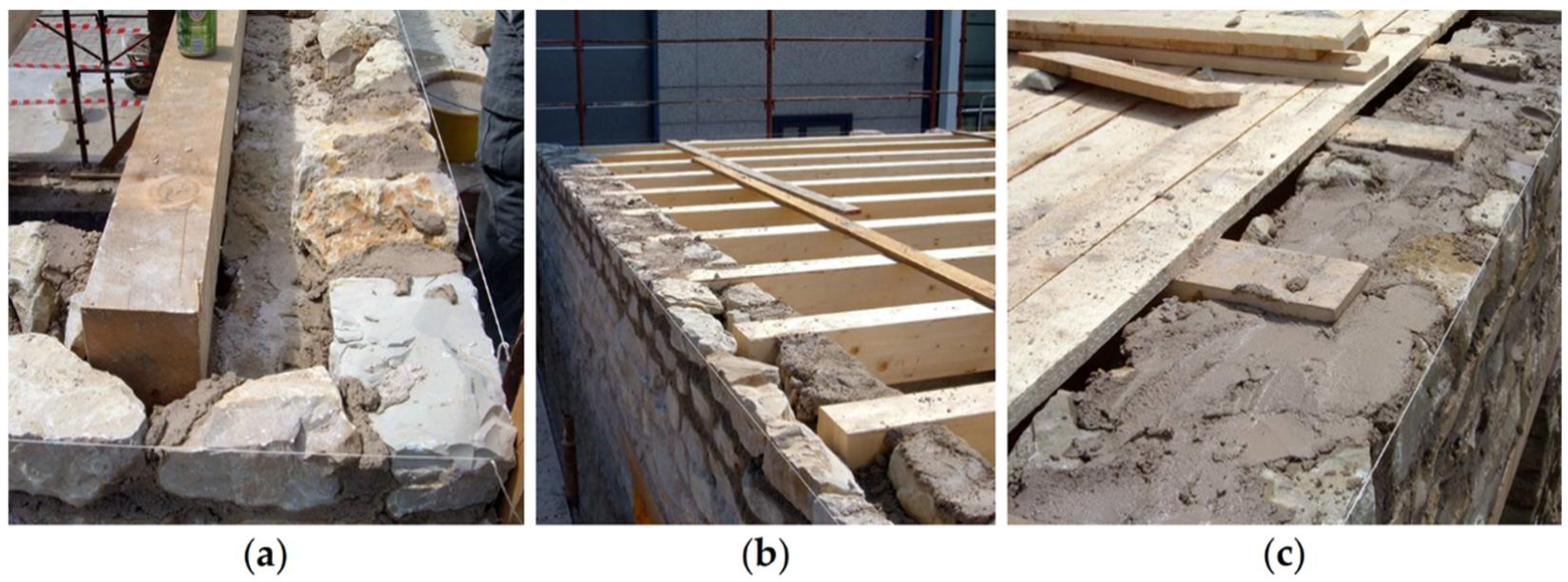
2.2. Timber Floor and Roof Structures

To reproduce the features of similar existing buildings, the reference timber floor framing system consisted of 12 × 16 cm joists, inserted within the internal leaf of the supporting longitudinal walls for about 15 to 20 cm (Figure 4a,b).
The inclined roof pitches consisted of 8 × 12 cm rafters, resting on spreader beams above the longitudinal walls and extending beyond them by approximately 15 cm, to simulate the roof eaves (Figure 5a,b). The rafters were also supported by a 20 × 32 cm ridge beam. Thin perforated steel plates ensure connection between each pair of rafters matching above the ridge beam (Figure 5c).
Floor and roof diaphragms were completed by a single layer of 3-cm-thick timber planks, nailed to the floor joists and roof rafters (Figure 4c and Figure 5b). The roof was covered with clay tiles, nailed to the timber planks to avoid any sliding of the tiles during the dynamic tests.
Building 1 was simply constructed according to the reference details of the unstrengthened prototype, with flexible floor and roof diaphragms. Different retrofit interventions were added to the floors and roofs of Building 2 and Building 3 to increase the diaphragm stiffness, as described in the following paragraphs.

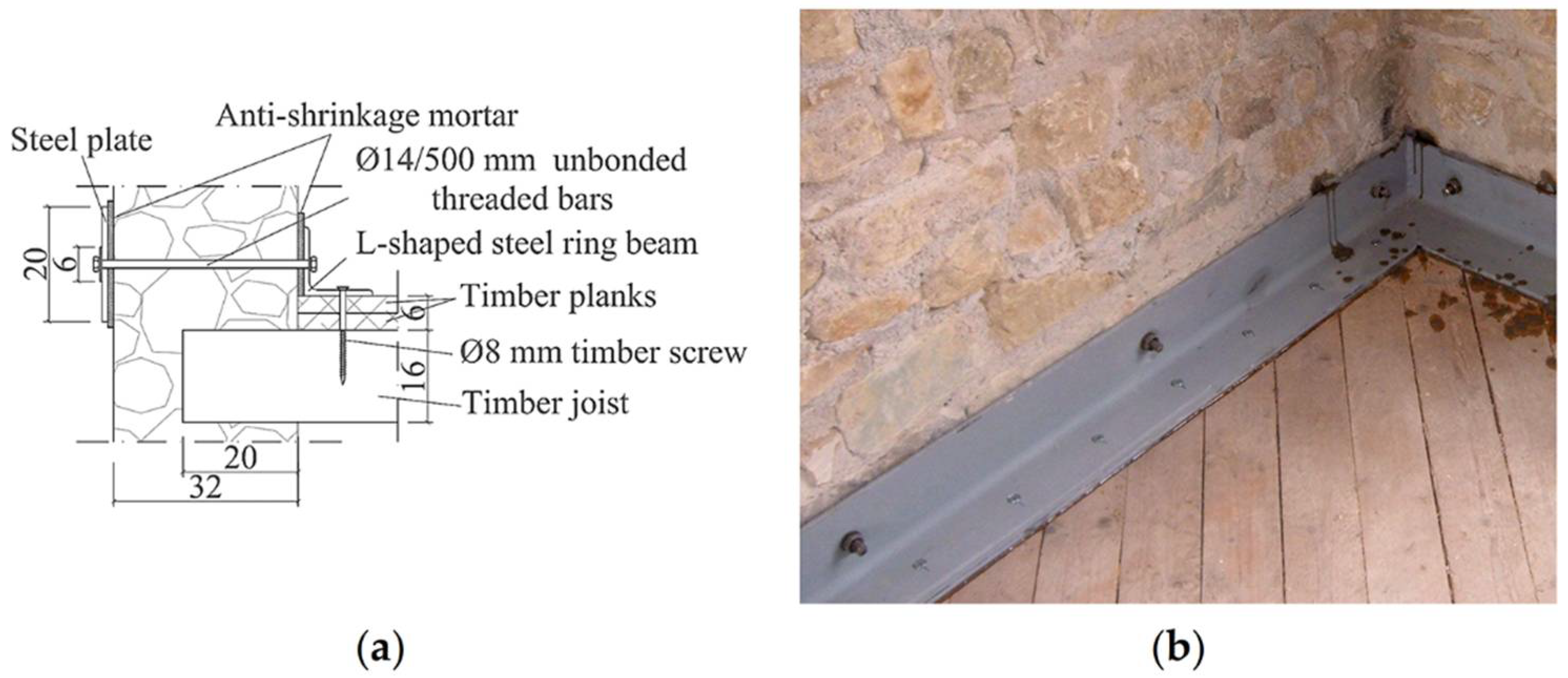
2.3. Retrofit of First-Floor Diaphragms and Connections

The retrofit interventions applied on Building 2 [52] aimed mainly at enhanced connection between the masonry walls and the first-floor diaphragm, while only moderately increasing the timber floor in-plane stiffness. Common interventions from building strengthening practice were selected for these purposes.
Steel angles with dimensions of 120 × 120 × 10 mm were used as a ring beam to allow an easy connection with the timber floor and the masonry walls, as shown in Figure 6a. The ring beam was connected to external rectangular steel anchor plates by pre-tensioned 14-mm-diameter threaded bars, unbonded through the wall thickness. Anti-shrinkage mortar was applied between steel angles or plates and masonry surfaces to create an even and distributed contact interface and a homogeneous confinement effect against out-of-plane wall overturning.
The floor in-plane stiffness of Building 2 was moderately increased by adding a second layer of diagonal timber planks, oriented at 45 degrees with respect to the existing floor joists and planks (Figure 6b). The planks were connected to the joists underneath, using at least two nails at intermediate intersections and four nails when connecting two adjacent planks to the same joist.
On the other hand, strengthening of the first floor of Building 3 [53] was designed not only to improve its connection with the walls, but also to significantly increase the in-plane diaphragm stiffness, implementing another common approach [61].
A 7-cm-thick lightweight concrete slab was cast above the original floor structure (Figure 7a), connected to the timber floor by shear connectors consisting of 14-mm-diameter reinforcing bars bent at 90 degrees [62] (Figure 7c). The connectors crossed through the planks and were chemically anchored to the floor joists at a spacing of 30 cm. The slab was reinforced by a 15 × 15 cm steel welded mesh of 8-mm-diameter bars (Figure 7c,d).
Threaded bars 14 mm in size were embedded by 100 cm in the RC slab and tied against external steel plates (Figure 7b,c), to enhance the wall-to-diaphragm connection and prevent the activation of overturning mechanisms. Anti-shrinkage mortar was applied between steel plates and masonry walls to regularize the contact interface.

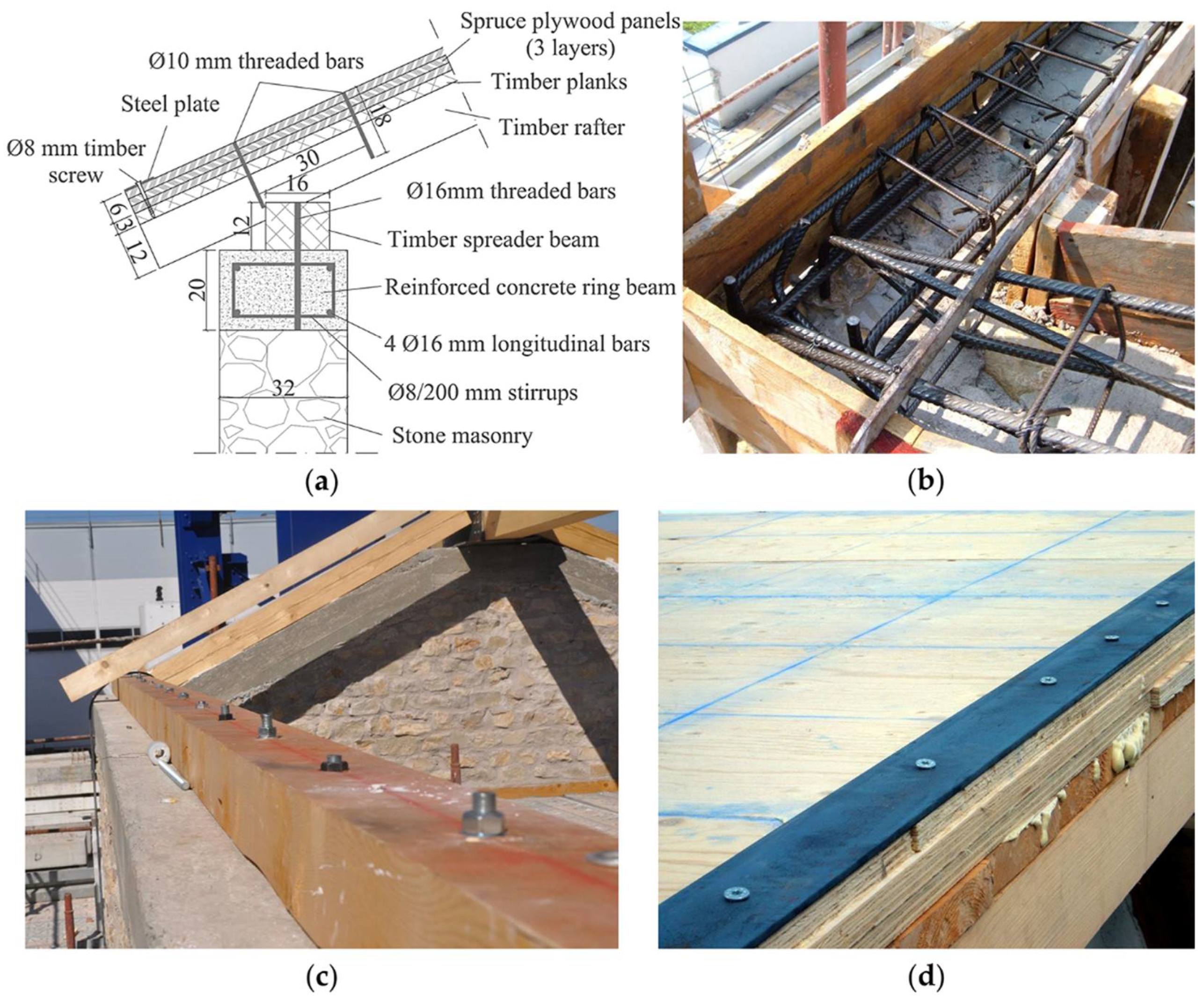
2.4. Retrofit of Roof Diaphragms and Connections

The roof retrofit of Building 2 [52] was conceived mainly to enhance the connection between walls and diaphragm, while only moderately increasing the timber pitches in-plane stiffness, as was carried out for the first-floor diaphragm.
The wall-to-roof diaphragm connection of Building 2 was enhanced with a RM ring beam, made of two solid brick veneers and an inner cement mortar core, located above the masonry walls (Figure 8a). The ring beam was longitudinally reinforced with three layers of 26-cm-wide, 5-mm-diameter reinforcement trusses, placed in the bed-joints and connecting the brick veneers (Figure 8c). Two 16-mm-diameter reinforcing bars were located in the mortar core above the longitudinal walls, while two 12-mm-diameter bars were provided above the gables (Figure 8d).
The perimeter timber spreader beam was doweled to the RM ring beam by pairs of chemically anchored 16-mm-diameter threaded bars, spaced at 80 cm above the longitudinal walls and at 75 cm above the gables, while the ridge beam was anchored to a steel shoe fixed to the ring beam (Figure 8b). To avoid the dispersion of epoxy resin into the masonry voids during injection, a steel sock was inserted in the holes accommodating the threaded bars.
The timber roof pitches were strengthened by adding a second layer of diagonal timber planks, oriented at 45 degrees with respect to the existing floor joists and planks, similarly to the intervention executed on the first-floor diaphragm.
An RC ring beam was provided above the longitudinal walls and transverse gables of Building 3 [53] to improve connection with the roof, while the timber roof pitches were stiffened by multilayer spruce plywood panels (Figure 9a).
The 32 × 20 cm RC ring beam was cast on top of all perimeter walls. The reinforcement consisted of four 16-mm-diameter longitudinal bars and 8-mm-diameter stirrups spaced at 20 cm (Figure 9b). The rafters were supported by a 16 × 12 cm timber spreader beam, doweled to the RC ring beam every 40 cm by chemically anchored 16-mm-diameter threaded bars (Figure 9c).
The roof diaphragm (Figure 9d) was stiffened by adding three layers of 2-cm-thick spruce plywood panels, glued to the planks and to each other with polyurethane adhesive and connected to the rafters by 10-mm-diameter chemically anchored steel bars every 30 cm. Panels of adjacent layers were staggered to avoid aligned joints. To improve the mechanical behavior of the roof, 80 × 5 mm continuous steel plates were placed all along the perimeter of each pitch.

2.5. Material Properties and Masses

The mechanical properties of the masonry constituting the three building specimens were determined from vertical compression and diagonal compression tests [54]. Table 1 summarizes the mean values and the dispersions of Young’s and shear moduli, E and G , as well as of compressive and tensile strengths, f m and f t .
C25/30 concrete (normal weight for the ring beam, lightweight for the slab) and B450 steel reinforcement were used for the strengthening interventions applied to Building 3, whereas the tests performed on the cement mortar used for the RM ring beam of Building 2 provided a mean compressive of approximately 15 MPa. Young’s and shear moduli of 10,000 MPa and 630 MPa, respectively, were assumed for all timber components, corresponding to class C22 timber [63,64].
A list of the nominal density of the construction materials is given in Table 2. Additional masses of 2 kN/m2 were distributed on the first floor of each building specimen, to simulate the pavement load plus 30% of residential live load. The tiles installed on the roof provided a total weight of 12.7 kN.

2.6. Testing Protocol and Results

The three building specimens were subjected to a similar sequence of unidirectional dynamic tests, with increasing ground motion intensity obtained by scaling the amplitude of the selected signal to predefined nominal peak ground acceleration (PGA) levels [51,52,53]. The Ulcinj-Hotel Albatros station East–West record of the 15 April 1979 Montenegro event was used for all dynamic tests, to allow for the comparison of the damage progression and of the effect of the selected retrofit techniques.
For all three buildings, the first test was carried out with nominal PGA of 0.05 g; then, amplitude scaling factors were increased up to reaching a near collapse conditions. Table 3 outlines the testing sequence for the three specimens, with the recorded PGA for each test run. Discrepancies between the PGA actually recorded for the different specimens occurred because of difficulties in the control procedure of the shaking table.
Building 1 was subjected to the last test at PGA of 0.70 g only after tightening pre-installed tie-rods to contrast out of-plane local mechanisms already activated; because of this variation in the structural configuration, this test run is not given further consideration. Additionally, the last test of Building 3, representing a lower-intensity aftershock with PGA of 0.66 g, is not taken into account in the following discussion.
Figure 10a shows the backbone curves in terms of total base shear versus average top displacement (at the roof base), by taking the points corresponding to maximum positive and negative base shear with the associated displacement from each test run; only the last point of each curve is taken at the maximum positive or negative displacement with the corresponding base shear. Figure 10b represents instead the incremental dynamic test (IDT) curves in terms of maximum absolute recorded PGA versus maximum absolute average top displacement from each test run.
The reference Building 1 was characterized by smaller lateral strength and displacement capacity compared to retrofitted Building 2 and Building 3, and reached near-collapse conditions at a PGA of 0.63 g due to out-of-plane overturning of the upper portions of the transverse façades. Instead, Building 2 and Building 3 exhibited a global response up to higher PGA intensities of 1.16 g and 1.49 g, respectively, thanks to the effectiveness of the enhanced wall-to-diaphragm connections. Their ultimate conditions were associated with in-plane failure mechanisms rather than out-of-plane local overturning.
The IDT curves of Figure 10b show that the same displacement demand was reached for higher PGA as the connections were enhanced with minor floor stiffness variation (Building 2 compared to Building 1) and as the diaphragms were significantly stiffened (Building 3 compared to Building 2). In particular, despite similar lateral strength, Building 3 underwent smaller displacement demand under higher PGA compared to Building 2, thanks to better engagement of all longitudinal and transverse piers by the nearly rigid diaphragms.
None of the specimens suffered from masonry disgregation, leaf delamination, or wall separation at corners, even though the masonry was characterized by relatively low strength. This performance was achieved thanks to a combination of mortar binding quality, sharp-cornered stones, and absence of loose filling, representative of good existing or improved stone masonry.

3. Numerical Simulations

3.1. Modeling Strategy

Several approaches can be followed to model masonry structures, ranging from the most complex micro-modelling techniques to simplified methods based on limit analysis, equivalent truss models, or story mechanisms [58]. In this study, the intermediate strategy of three-dimensional equivalent-frame modeling was adopted, as it is one of the most widely used in professional practice to reproduce the global response of masonry buildings. This choice is particularly appropriate to simulate the response of structures with fairly regular wall layouts when local mechanisms are prevented. The TREMURI program [57] was chosen for this purpose.
The software simulates the behavior of an entire building by assembling vertical walls and horizontal diaphragms, referring to their in-plane strength and stiffness contributions. Walls are discretized into two-node macroelements [58], corresponding to pier (vertical) and spandrel (horizontal) members, and rigid nodal regions at their intersections. These macroelements allow one to reproduce the two main in-plane failure mechanisms of a masonry panel (flexure and shear), keeping a reasonable compromise between the accuracy of the results and computational effort.
Various strategies are proposed in the literature and codes to discretize masonry walls into macroelements [65]. In this work, the pier height was taken as equal to the one of the adjacent openings, to capture better the damage mechanisms observed during the shake-table tests and to account for the presence of timber lintels anchored into the masonry walls, which effectively prevented the diffusion of cracks in the nodal regions [66].
The structural behavior of a building is strongly affected by the in-plane stiffness of floor and roof diaphragms. For this reason, TREMURI includes linear three- or four-node orthotropic membrane finite elements, with two in-plane displacement degrees of freedom at each node. Moreover, the equivalent-frame model of a wall allows one to introduce other structural elements, such as steel, RC, and RM ring beams, with both linear and nonlinear beam element formulation.
The out-of-plane flexural responses of diaphragms and walls are not accounted for because they are considered negligible in the context of the global building response, which is governed by their in-plane behavior. As a consequence, local disgregation, delamination, and out-of-plane overturning mechanisms cannot be captured by this modeling technique: in fact, the underlying assumption of global building modeling is that local mechanisms are inhibited. For this reason, only Building 2 and Building 3 models were analyzed, since the failure of Building 1 was governed by local overturning of the transverse façades [51].
As shown in Figure 11, the four walls of the models representing the two buildings were very similar to each other. Differences were limited to cross-sections and materials assigned to diaphragms and ring-beams. All masses actually present in the experimental building specimens were considered in the models. In particular, the stone masonry mass was automatically obtained by assigning its density to nodal regions and macroelements: a reduced value of 2200 kg/m3 was used to account for the penetration of lighter timber lintels and joists in the walls. Floor, roof, retrofit components, and additional masses were instead assigned as lumped nodal values.

3.2. Calibration of Masonry Material Properties

The masonry mechanical properties adopted in the numerical models were derived from a comprehensive characterization campaign carried out on material samples and components built together with the three building specimens at the EUCENTRE Foundation and University of Pavia laboratories [54,55,56].
In particular, the normal compressive strength was directly taken as the mean value from vertical compression tests on wallettes [54]. Instead, the Young modulus E and the shear modulus G assigned to the macroelements were different from the values obtained from the characterization tests. In fact, the two specimens were built elsewhere and then transported on the shake-table, resulting in some preliminary cracking [52,53]. For this reason, stiffness parameters of masonry macroelements were reduced to 80% of the characterization values. All spandrels and some piers were particularly damaged in Building 3: only 40% of the elastic moduli were assigned to the corresponding macroelements.
The tensile strength associated with diagonal shear cracking was derived from quasi-static cyclic shear-compression tests on four piers [55] rather than from diagonal compression tests to account for geometric and axial load effects. The specimen dimensions were chosen to be representative of slender and squat piers of the building prototype. The two specimens of each geometry were tested under distinct levels of axial compression.
At the end of each test, the maximum positive and negative values of shear strength V R + and V R were recorded. By inverting Turnsek and Sheppard’s strength criterion [67], the corresponding tensile strengths f t + and f t were obtained from Equation (1):
V R = l t f t b 1 + σ 0 f t
where l , h , and t are pier length, height, and thickness, respectively, b = h / l is a coefficient accounting for the shear stress distribution in the center of the panel, and σ 0 is the axial compressive stress. A summary of the tensile strength calculations is reported in Table 4. It can be noted that almost all the tensile strength values determined from cyclic shear-compression tests fall around the mean value from diagonal compression tests (0.137 MPa) plus or minus one standard deviation (0.031 MPa).
As the shear failure criterion of the macroelement implemented in TREMURI is based on a Coulomb model, equivalent cohesion c e q and friction coefficient μ e q can be calculated by linearizing the Turnsek and Sheppard’s criterion [67] around the static axial load N 0 = l t σ 0 due to gravity loads only [66], according to Equation (2):
{ μ e q = d V R d N | N 0 = 1 2 b f t f t + N 0 / l t c e q = f t b 1 + N 0 l t   f t μ e q N 0 l t
The equivalent parameters were assigned, distinguishing between slender piers, squat piers, and spandrels. For slender piers, the upper-bound tensile strength of 0.18 MPa from Table 4, the static axial load acting on the first-story West-wall central pier (68 kN for Building 2, while 78 kN for Building 3), and element dimensions of 1.30 × 1.80 × 0.32 m were considered. Instead, for squat piers, the lower-bound tensile strength of 0.10 MPa, the axial load on the first-story East-wall squat pier (149 kN for Building 2, while 173 kN for Building 3), and dimensions of 3.55 × 1.25 × 0.32 m were used. The same equivalent cohesion and friction coefficient of the slender piers were also applied to the spandrels.
Parameters G c t and β complete the definition of the nonlinear shear response of the macroelement [58]. In particular, G c t controls the shear deformation corresponding to the peak strength, while β governs the softening branch following the peak. All mechanical properties assigned to the macroelements of the two models are summarized in Table 5.

3.3. Calibration of Membrane and Beam Element Stiffness

The in-plane stiffness of floor and roof diaphragms can be simulated in TREMURI through orthotropic membrane elements with linear elastic formulation. The mechanical properties of the aforementioned elements are defined through a principal direction, with Young modulus E 1 , an orthogonal direction, with Young modulus E 2 , the Poisson coefficient ν , and the shear modulus G 12 . The most critical parameter is the last one, which influences the diaphragm shear stiffness and its ability to redistribute lateral forces among masonry walls, both in linear and nonlinear phases.
In this work, the mechanical properties for floor and roof diaphragms were evaluated with Equation (3):
{ E 1 = E t j A j / s j + E t a t a sin 2 φ a + E t p t p + E c t c t m E 2 = E t e t e + E t a t a cos 2 φ a + E t p t p + E c t c t m G 12 = C d G 12 , e t e + G c t c t m
where the equivalent shear modulus of the originally existing timber diaphragm, G 12 , e , includes the three in-series contributions [68] due to flexural and shear deformation of each plank and rigid rotation of the plank due to nail slip, according to Equation (4):
G 12 , e = χ A e · ( s j 2 12 · E t e · I e + χ G t e · A e + s j k s e r · s n 2 ) 1
The symbols that appear in Equations (3) and (4) have the following meanings:
  • E 1 is oriented parallel to the timber joists, orthogonal to the shaking direction;
  • E 2 is oriented parallel to the original timber planks and to the shaking direction;
  • t m is the thickness assigned to the model membrane;
  • E t j is the Young modulus of timber for the joists;
  • A j and s j are the cross-section area and the spacing of the timber joists;
  • E t e and G t e are the Young and shear moduli of timber for the existing planks;
  • t e , A e , and I e are the thickness, cross-section area, and moment of inertia of each existing timber planks;
  • E t a is the Young modulus of timber for the additional planks;
  • t a and φ a are the thickness of the additional timber planks or panels and their orientation with respect to the existing planks;
  • E t p is the Young modulus of timber for the additional panels;
  • t p is the thickness of the additional timber panels;
  • E c and G c are the Young and shear moduli of concrete;
  • t c is the thickness of the additional reinforced concrete slab;
  • k s e r is the nailed connection stiffness according to Eurocode 5 [69];
  • s n is the nail spacing at a plank–joist intersection;
  • χ = 1.2 is the shear factor for a rectangular cross-section;
  • C d is a correction coefficient accounting for additional timber layers.
Correction coefficients C d were applied to the equivalent shear modulus derived from Equation (4), to account for retrofit interventions increasing the diaphragm stiffness through further planks or plywood layers [70]. C d = 5 was chosen for the floor and roof diaphragms in Building 2, where an additional plank layer was provided with 45° orientation with respect to the original one. Coefficient C d = 20 was instead used to simulate Building 3 roof improvement with three additional layers of plywood panels.
The lightweight RC slab cast on the floor of Building 3 was explicitly modeled by considering its collaboration with the timber floor underneath, as expressed by Equation (3). The Young’s modulus of concrete was calculated according to Eurocode 2 [71] and the Italian building code [59,60] based on the concrete strength class and density. The concrete shear modulus was approximated as G c = E c / 2.6 .
The values of the main parameters assigned to the floor and roof diaphragms are reported in Table 6. It is noteworthy that combining the literature formulations with the material properties adopted for the specimens resulted in good agreement with the experimental results without further calibration of the diaphragm models.
The quality of the wall-to-diaphragm connections was improved by steel, RM, or RC ring beams. These components were modeled using linear elastic beam elements with axial stiffness corresponding to the actual material and cross-section area. The clay RM elastic moduli were calibrated in a previous numerical study of the same test campaign [66].
The out-of-plane flexural stiffness of the lightweight RC slab of Building 3 was also simulated through linear beam elements, with the moment of inertia corresponding to the actual slab thickness and half the floor width perpendicular to the element; the cross-section area of these elements was set to zero, as the slab axial stiffness was already assigned to the linear elastic membrane.
Table 7 lists the main properties assigned to the linear elastic beam elements.

3.4. Comparison between Numerical and Experimental Results

Nonlinear static (pushover) analyses were performed on three-dimensional models of the two retrofitted buildings described in the previous sections, in order to reproduce the experimental backbone force–displacement curves. Pushover analyses were carried out considering two different horizontal load patterns. The first one, named “Modal”, consisted of a first-mode-type force distribution, with forces proportional to the product of nodal masses times the nodal height above the base. In contrast, the second load pattern, termed “Uniform”, consisted of a force distribution proportional only to the nodal masses. Due to the vertical regularity and the diaphragm stiffness of both buildings, other load patterns were not deemed relevant [72].
Figure 12 compares experimental backbone curves with numerical pushover curves. In particular, since most of the damage occurred at the first story in both buildings, the uniform distribution (proportional to nodal masses) resulted in curves closer to the experimental backbones for stiffness and strength. Consequently, the modal distribution will not be given further consideration. Given the asymmetric experimental response of Building 3, a slightly larger discrepancy between numerical and experimental curves can be observed than for Building 2.
As depicted in Figure 13 and Figure 14, both numerical models were able to correctly capture the damage patterns observed on masonry piers and spandrels at the end of the shake-table tests. Lines perpendicular to the macroelement axis close to its ends indicate the extent of flexural cracks. A cross through a macroelement means that its shear strength was reached. Colors ranging from yellow to brown correspond to increasing levels of shear damage from moderate to post-peak phase, while a green color indicates axial tension instead. Both the flexural–rocking mechanism, that characterized the West façade, and the shear mechanism, observed on the East one, were properly simulated. Moreover, the numerical models correctly reproduced the shear cracking of the transverse South wall engaged by global torsion of the whole structure.

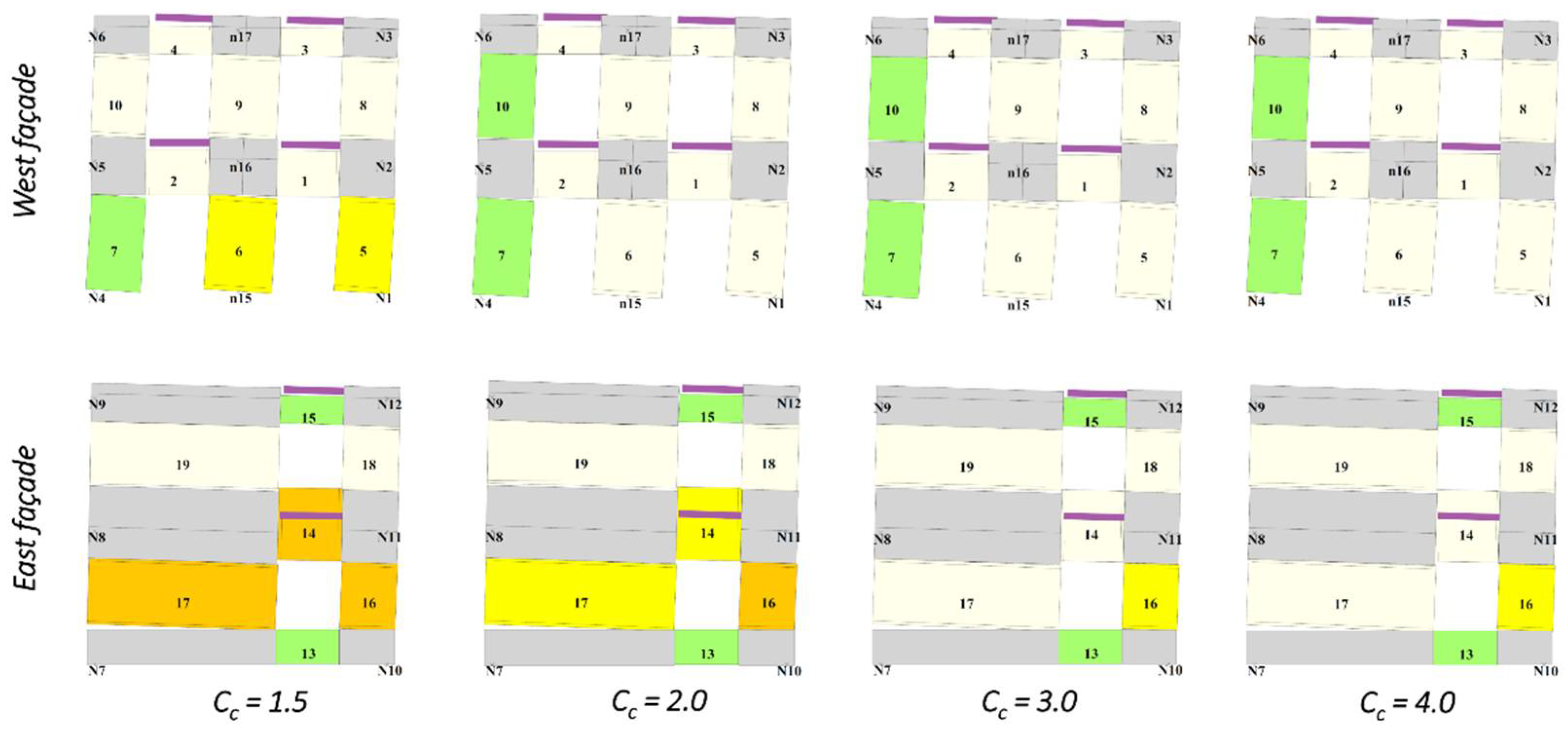
3.5. Paramateric Study on Masonry Mechanical Improvements

Various techniques can be used in the professional practice to increase the masonry mechanical characteristics: their choice should be guided by consideration of compatibility with the existing substrate. Deep joint repointing and jacketing are two solutions often adopted for this purpose. The parametric study discussed herein focuses on some macroscopic effects of masonry improvement on the overall seismic response of masonry buildings, without addressing specific construction details of any intervention.
Deep joint repointing consists in replacing low-quality mortar with better performing materials, reaching a depth of a few centimeters from the wall surface. Sometimes, steel reinforcement is embedded in the new mortar. Jacketing instead covers a variety of interventions with the application of composite materials to one or both surfaces of masonry walls. Fiber-reinforced polymers (FRP), fabric-reinforced cementitious matrices (FRCM), composite-reinforced mortars (CRM), and steel-reinforced grouts (SRG) are among the most common jacketing materials.
The effects of these techniques on the masonry strength and stiffness are highly dependent on the constituents, bond pattern, and thickness of the original walls. Moreover, the equivalent-frame modeling strategy adopted for this study, relying on macroelement discretization of the masonry walls, cannot explicitly encompass construction details of the material strengthening. In light of these considerations, the simplified approach proposed by the Italian building code [59,60] was followed, which estimates the mechanical enhancements through simple correction coefficients starting from unstrengthened material properties. This method was deemed appropriate to compare the overall impact of increasing levels of masonry mechanical improvements.
Consequently, a parametric study has been conducted with correction coefficients C c of 1.5 and 2.0, similar to the values proposed by the Italian building code for deep joint repointing and jacketing. Higher values of 3.0 and 4.0 have also been considered, to better cover the experimental range available in the literature for jacketing alternatives [41,44,46,47,49,50]. These coefficients were applied to the masonry Young’s and shear moduli, as well as compressive and tensile strengths. Due to the Coulomb-type shear strength criterion adopted for the macroelements, equivalent cohesion c e q and friction coefficient μ e q were recalculated based on the increased tensile strength using Equation (2).
Jacketing techniques rely on layers of composite materials with non-negligible tensile strength. These interventions can be detailed to provide tensile continuity with the foundation and across the floors, thus enhancing the pier axial tensile response. For this reason, the parametric study was repeated including the axial tensile strength for masonry macroelements, neglected so far. The mean tensile strength of 0.137 MPa from experimental material characterization [54] was assigned to the unstrengthened models. The same correction coefficients used for the other properties were also applied to the axial tensile strength in the retrofitted models.
Figure 15 shows the pushover curves obtained with the uniform load distribution for Building 2 and Building 3, applying correction coefficients C c between 1.5 and 4.0 and ignoring any axial tensile strength. Considering also an improved, non-zero axial tensile strength (Figure 16) had minor effects on the stiffness of both numerical models and on the strength of Building 3; however, it conferred more pronounced hardening to the response of Building 2. All analyses were stopped at a top displacement equal to the maximum demand from the dynamic tests.
It can be emphasized that applying correction coefficients beyond 1.5 resulted in a sort of saturation of the global lateral strength for both buildings. This can be understood by looking at Figure 17 and Figure 18, which depict the damage patterns when the maximum experimental displacement is achieved with the analyses. Increasing the correction coefficient resulted in lower shear damage to the macroelements. Shear failure on the East façade of the unstrengthened models transitioned into a global flexural mechanism on both longitudinal walls, with strength limited by rigid-body equilibrium and only barely sensitive to the material properties. The simultaneous enhancement of both axial and diagonal shear strength did not affect the failure mechanisms: in fact, a flexural behavior continued to govern the numerical responses with improved masonry properties.
The change of failure mechanism from shear to flexure and the increase in lateral strength, especially if associated with hardening behavior, constitute a combined positive effect for the general performance of masonry buildings. In fact, higher lateral strength usually results in smaller inelastic amplification of the seismic displacement demand [73,74]; however, care should be taken when choosing jacketing materials which add excessively to the lateral stiffness, as they may result in the opposite effect. Moreover, larger displacement capacity is typically associated with flexural than with shear failures, as recognized by building codes which provide deformation, drift or chord-rotation limitations for various failure modes of piers and spandrels [59,60].

4. Summary and Conclusions

This paper discussed the effectiveness of different seismic retrofit strategies for stone masonry buildings with flexible timber diaphragms, combining experimental and numerical findings.
Unidirectional incremental dynamic shake-table tests were performed on three full-scale two-story buildings, to prove the effectiveness of enhancing wall-to-diaphragm connections and increasing floor and roof diaphragm stiffness. A local out-of-plane overturning mechanism developed in the unstrengthened Building 1, but was inhibited by the selected interventions in Building 2 and Building 3. Moreover, the same lateral displacement demands were achieved under higher-intensity ground motion as connections were improved (Building 2 compared to Building 1) and diaphragms significantly stiffened (Building 3 compared to Building 2).
None of the specimens suffered from masonry disgregation, leaf delamination, or wall separation at corners, thanks to a combination of mortar binding quality, sharp-cornered stones, and the absence of loose filling, corresponding to good natural stone masonry. Generally, preliminary interventions may be required to address poor existing bond and constituents. Otherwise, connection improvement and diaphragm stiffening would result ineffective if the masonry walls could not resist the forces transferred locally.
Nonlinear pushover analyses were carried out on numerical three-dimensional models based on an equivalent-frame approach. The software TREMURI was used for this scope. Nonlinear macroelements represented the in-plane behavior of masonry piers and spandrels, while linear elastic elements that of diaphragms and ring beams. This modeling strategy cannot capture out-of-plane local mechanisms and is appropriate for structures governed by a global response. Consequently, only Building 2 and Building 3 were analyzed; Building 1 was excluded because it exhibited out-of-plane overturning of walls.
Material properties were calibrated versus the experimental results from material and component characterization tests, which were conducted on samples and components constructed together with the building units. A good match was achieved between the numerical pushover curves and the experimental backbone curves, as well as between the simulated and observed damage patterns on the masonry elements.
The two numerical models were subsequently modified to simulate masonry mechanical upgrades, which could be achieved in practice through deep joint repointing or various types of jacketing among other techniques. Construction details of the masonry enhancement could not be explicitly modeled with the chosen equivalent-frame strategy, relying on macroelement discretization. Consequently, these solutions were simulated through correction coefficients applied to the masonry elastic moduli, compressive, tensile and shear strength, as suggested by the Italian building code.
It was shown that, as the shear tensile strength of piers increases, the overall lateral strength tends to saturate. In fact, failure of the two buildings transitioned from shear to flexural mechanisms, with the flexural strength limited by rigid-body equilibrium and nearly independent of material properties. However, flexural mechanisms are generally associated with larger displacement capacity than shear failures, while higher lateral strength results in smaller inelastic amplification of the displacement demand, if the elastic period does not increase excessively. Combining these two effects together is expected to have a net positive impact on the seismic performance of masonry buildings in general.
Special details can be implemented with jacketing techniques to provide tensile continuity with the foundation and across the floors. This condition was modeled by accounting for the axial tensile strength of the piers, and by applying to it the same correction coefficient used for the other material properties. The simultaneous enhancement of shear and axial tensile strength resulted in appreciable differences only on Building 2, characterized by more deformable diaphragms: its pushover curves exhibited more pronounced hardening compared to the case of zero-axial tensile strength. This additional strength would result in further reduction in the inelastic displacement amplification.
The experimental and numerical results of this study confirmed that the biggest benefit was achieved by improving wall-to-diaphragm connections, because this allowed one to prevent the local out-of-plane overturning of a wall, and by stiffening timber diaphragms. Masonry mechanical enhancement induced additional positive effects, but to a lesser extent. These outcomes constitute the basis for future developments related to the selection and design of appropriate seismic retrofit measures for stone masonry buildings. Among other aspects, the optimal quantification of the required connection strength and diaphragm stiffness will be of particular interest.

Author Contributions

Conceptualization, G.G. and A.P.; methodology, G.G. and C.S.; software, A.P.; validation, G.G. and I.S.; formal analysis, C.S.; investigation, G.G. and C.S.; resources, A.P.; data curation, G.G.; writing—original draft preparation, G.G., C.S. and I.S.; writing—review and editing, A.P.; visualization, I.S. and C.S.; supervision, A.P.; project administration, A.P.; funding acquisition, A.P. All authors have read and agreed to the published version of the manuscript.

Funding

The experimental program, forming the basis for this research, was funded by the Italian Department of Civil Protection through the 2005–2008 EUCENTRE Executive Project, the 2005–2008 ReLUIS Project Line 1, and the 2010–2013 ReLUIS Project Task AT1-1.1. The numerical study was conducted within the 2019–2021 ReLUIS Project WP10 “Code contributions for existing masonry constructions”, funded by the Italian Department of Civil Protection.

Data Availability Statement

Data can be made available upon request to the corresponding author.

Acknowledgments

The authors would like to gratefully acknowledge the valuable contributions of G. Magenes, A. Galasco, F. Graziotti, M. Rota, and M. Da Paré to the experimental program and preliminary numerical simulations.

Conflicts of Interest

The authors declare no conflict of interest. The funders had no role in the design of the study; in the collection, analyses, or interpretation of data; in the writing of the manuscript, or in the decision to publish the results.

References

  1. D’Ayala, D.; Paganoni, S. Assessment and analysis of damage in L’Aquila historic city centre after the 6th April 2009. Bull. Earthq. Eng. 2011, 9, 81–104. [Google Scholar] [CrossRef]
  2. Carocci, C.F. Small centres damaged by 2009 L’Aquila earthquake: On site analyses of historical masonry aggregates. Bull. Earthq. Eng. 2012, 10, 45–71. [Google Scholar] [CrossRef]
  3. Da Porto, F.; Silva, B.; Costa, C.; Modena, C. Macro-Scale Analysis of Damage to Churches after Earthquake in Abruzzo (Italy) on April 6, 2009. J. Earthq. Eng. 2012, 16, 739–758. [Google Scholar] [CrossRef]
  4. Lagomarsino, S. Damage assessment of churches after L’Aquila earthquake (2009). Bull. Earthq. Eng. 2011, 10, 73–92. [Google Scholar] [CrossRef]
  5. Penna, A.; Calderini, C.; Sorrentino, L.; Carocci, C.F.; Cescatti, E.; Sisti, R.; Borri, A.; Modena, C.; Prota, A. Damage to churches in the 2016 central Italy earthquakes. Bull. Earthq. Eng. 2019, 17, 5763–5790. [Google Scholar] [CrossRef]
  6. Sorrentino, L.; Cattari, S.; da Porto, F.; Magenes, G.; Penna, A. Seismic behaviour of ordinary masonry buildings during the 2016 central Italy earthquakes. Bull. Earthq. Eng. 2019, 17, 5583–5607. [Google Scholar] [CrossRef] [Green Version]
  7. Tomaževič, M.; Weiss, P.; Velechovsky, T. The influence of rigidity of floors on the seismic behaviour of old stone-masonry buildings. Eur. Earthq. Eng. 1991, 3, 28–41. [Google Scholar]
  8. Benedetti, D.; Carydis, P.; Pezzoli, P. Shaking table test on 24 masonry buildings. Earthq. Eng. Struct. Dyn. 1998, 27, 67–90. [Google Scholar] [CrossRef]
  9. Rota, M.; Penna, A.; Strobbia, C.; Magenes, G. Typological Seismic Risk Maps for Italy. Earthq. Spectra 2011, 27, 907–926. [Google Scholar] [CrossRef]
  10. Costa, A.A.; Arede, A.; Costa, A.; Penna, A.; Costa, A. Out-of-plane behaviour of a full-scale stone masonry façade. Part 1: Specimen and ground motion selection. Earthq. Eng. Struct. Dyn. 2013, 42, 2081–2095. [Google Scholar] [CrossRef]
  11. Costa, A.A.; Arêde, A.; Costa, A.C.; Penna, A.; Costa, A. Out-of-plane behaviour of a full scale stone masonry façade. Part 2: Shaking table tests. Earthq. Eng. Struct. Dyn. 2013, 42, 2097–2111. [Google Scholar] [CrossRef]
  12. Senaldi, I.E.; Guerrini, G.; Comini, P.; Graziotti, F.; Penna, A.; Beyer, K.; Magenes, G. Experimental seismic performance of a half-scale stone masonry building aggregate. Bull. Earthq. Eng. 2019, 18, 609–643. [Google Scholar] [CrossRef]
  13. Tolles, E.L.; Webster, F.A.; Crosby, A.; Kimbro, E.E. Survey of Damage to Historic Adobe Buildings after the January 1994 Northridge Earthquake; The Getty Conservation Institute: Los Angeles, CA, USA, 1996. [Google Scholar]
  14. Vintzileou, E.; Mouzakis, C.; Adami, C.-E.; Karapitta, L. Seismic behavior of three-leaf stone masonry buildings before and after interventions: Shaking table tests on a two-storey masonry model. Bull. Earthq. Eng. 2015, 13, 3107–3133. [Google Scholar] [CrossRef]
  15. Mouzakis, C.; Adami, C.-E.; Karapitta, L.; Vintzileou, E. Seismic behaviour of timber-laced stone masonry buildings before and after interventions: Shaking table tests on a two-storey masonry model. Bull. Earthq. Eng. 2017, 16, 803–829. [Google Scholar] [CrossRef]
  16. Decanini, L.; de Sortis, C.A.; Goretti, A.; Langenbach, R.; Mollaioli, F.; Rasulo, A. Performance of Masonry Buildings during the 2002 Molise, Italy, Earthquake. Earthq. Spectra 2004, 20 (Suppl. 1), 191–220. [Google Scholar] [CrossRef]
  17. Binda, L.; Cardani, G.; Saisi, A. A classification of structures and masonries for the adequate choice of repair. In Proceedings of the International RILEM Workshop on Repair Mortars for Historic Masonry, Delft, The Netherlands, 26–28 January 2005. [Google Scholar]
  18. Valluzzi, M.R. On the vulnerability of historical masonry structures: Analysis and mitigation. Mater. Struct. 2006, 40, 723–743. [Google Scholar] [CrossRef]
  19. Modena, C.; Valluzzi, M.R.; da Porto, F.; Casarin, F. Structural Aspects of The Conservation of Historic Masonry Constructions in Seismic Areas: Remedial Measures and Emergency Actions. Int. J. Arch. Herit. 2011, 5, 539–558. [Google Scholar] [CrossRef]
  20. Sisti, R.; Di Ludovico, M.; Borri, A.; Prota, A. Damage assessment and the effectiveness of prevention: The response of ordinary unreinforced masonry buildings in Norcia during the Central Italy 2016–2017 seismic sequence. Bull. Earthq. Eng. 2019, 17, 5609–5629. [Google Scholar] [CrossRef]
  21. Karantoni, F.V.; Fardis, M. Effectiveness of Seismic Strengthening Techniques for Masonry Buildings. J. Struct. Eng. 1992, 118, 1884–1902. [Google Scholar] [CrossRef]
  22. Frumento, S.; Giovinazzi, S.; Lagomarsino, S.; Podestà, S. Seismic retrofitting of unreinforced masonry buildings in Italy. In Proceedings of the New Zealand Society for Earthquake Engineering Conference, Napier, New Zealand, 10–12 March 2006. [Google Scholar]
  23. Modena, C.; Valluzzi, M.R.; Garbin, E.; da Porto, F. A strengthening technique for timber floors using traditional materials. In Proceedings of the 4th Structural Analysis of Historical Constructions Conference, Padova, Italy, 10–12 November 2004. [Google Scholar]
  24. Moreira, S.M.T.; Ramos, L.F.; Oliveira, D.V.; Lourenco, P. Experimental behavior of masonry wall-to-timber elements connections strengthened with injection anchors. Eng. Struct. 2014, 81, 98–109. [Google Scholar] [CrossRef] [Green Version]
  25. Moreira, S.; Ramos, L.F.; Oliveira, D.V.; Lourenco, P. Design Parameters for Seismically Retrofitted Masonry-To-Timber Connections: Injection Anchors. Int. J. Arch. Herit. 2015, 10, 217–234. [Google Scholar] [CrossRef] [Green Version]
  26. Guerrini, G.; Senaldi, I.; Graziotti, F.; Magenes, G.; Beyer, K.; Penna, A. Shake-Table Test of a Strengthened Stone Masonry Building Aggregate with Flexible Diaphragms. Int. J. Arch. Herit. 2019, 13, 1078–1097. [Google Scholar] [CrossRef]
  27. Tomaževič, M.; Lutman, M.; Weiss, P. Seismic Upgrading of Old Brick-Masonry Urban Houses: Tying of Walls with Steel Ties. Earthq. Spectra 1996, 12, 599–622. [Google Scholar] [CrossRef]
  28. Celik, O.; Sesigur, H.; Cili, F. Importance of wood and iron tension members on seismic performance of historic masonry buildings: Three case studies from Turkey. In Proceedings of the ATC and SEI Conference on Improving the Seismic Performance of Existing Buildings and Other Structures, San Francisco, CA, USA, 9–11 December 2009. [Google Scholar]
  29. Calderini, C.; Lagomarsino, S.; Rossi, M.; de Canio, G.; Mongelli, M.L.; Roselli, I. Shaking table tests of an arch-pillars system and design of strengthening by the use of tie-rods. Bull. Earthq. Eng. 2014, 13, 279–297. [Google Scholar] [CrossRef]
  30. Podestà, S.; Scandolo, L. Earthquakes and Tie-Rods: Assessment, Design, and Ductility Issues. Int. J. Arch. Herit. 2019, 13, 329–339. [Google Scholar] [CrossRef]
  31. Tolles, E.L.; Kimbro, E.E.; Webster, F.A.; Ginell, W.S. Seismic Stabilization of Historic Adobe Structures. Final Report of the Getty Seismic Adobe Project; The Getty Conservation Institute: Los Angeles, CA, USA, 2000. [Google Scholar]
  32. Sikka, S.; Chaudhry, C. Research on the Upgrade of Traditional Seismic Retrofits for Ancient Buddhist Temples in the Region of Spiti and Kinnaur in the Western Himalayas. In Proceedings of the Getty Seismic Adobe Project 2006 Colloquium, Los Angeles, CA, USA, 11–13 April 2006; Hardy, M., Cancino, C., Ostergren, G., Eds.; The Getty Conservation Institute: Los Angeles, CA, USA, 2009. [Google Scholar]
  33. Borri, A.; Castori, G.; Grazini, A. Retrofitting of masonry building with reinforced masonry ring-beam. Constr. Build. Mater. 2009, 23, 1892–1901. [Google Scholar] [CrossRef]
  34. Guadagnuolo, M.; Faella, G. Simplified Design of Masonry Ring-Beams Reinforced by Flax Fibers for Existing Buildings Retrofitting. Buildings 2020, 10, 12. [Google Scholar] [CrossRef] [Green Version]
  35. Piazza, M.; Baldessari, C.; Tomasi, R. The role of in-plane floor stiffness in the seismic behaviour of traditional buildings. In Proceedings of the 14th World Conference on Earthquake Engineering, Beijing, China, 12–17 October 2008. [Google Scholar]
  36. Valluzzi, M.R.; Garbin, E.; Dalla Benetta, M.; Modena, C. In-plane strengthening of timber floors for the seismic improvement of masonry buildings. In Proceedings of the 11th World Conference on Timber Engineering, Riva del Garda, Italy, 20–24 June 2010. [Google Scholar]
  37. Nunes, M.; Bento, R.; Lopes, M. In-plane stiffening and strengthening of timber floors for the improvement of seismic behaviour of URM buildings. Int. J. Mason. Res. Innov. 2020, 5, 85. [Google Scholar] [CrossRef]
  38. Valluzzi, M.R.; Binda, L.; Modena, C. Experimental and analytical studies for the choice of repair techniques applied to historic buildings. Mater. Struct. 2002, 35, 285–292. [Google Scholar] [CrossRef]
  39. Mazzon, N.; Chavez, C.M.; Valluzzi, M.R.; Casarin, F.; Modena, C. Shaking Table Tests on Multi-Leaf Stone Masonry Structures: Analysis of Stiffness Decay. Adv. Mater. Res. 2010, 133–134, 647–652. [Google Scholar] [CrossRef]
  40. Vintzileou, E.N.; Toumbakari, E.E. The effect of deep rejointing on the compressive strength of brick masonry. In Historical Constructions; Lourenço, P.B., Roca, P., Eds.; University of Minho: Guimarães, Portugal, 2001; pp. 995–1002. [Google Scholar]
  41. Corradi, M.; Tedeschi, C.; Binda, L.; Borri, A. Experimental evaluation of shear and compression strength of masonry wall before and after reinforcement: Deep repointing. Constr. Build. Mater. 2008, 22, 463–472. [Google Scholar] [CrossRef] [Green Version]
  42. Prota, A.; Marcari, G.; Fabbrocino, G.; Manfredi, G.; Aldea, C. Experimental In-Plane Behavior of Tuff Masonry Strengthened with Cementitious Matrix–Grid Composites. J. Compos. Constr. 2006, 10, 223–233. [Google Scholar] [CrossRef]
  43. Papanicolaou, C.G.; Triantafillou, T.C.; Karlos, K.; Papathanasiou, M. Textile-reinforced mortar (TRM) versus FRP as strengthening material of URM walls: In-plane cyclic loading. Mater. Struct. 2006, 40, 1081–1097. [Google Scholar] [CrossRef]
  44. Borri, A.; Castori, G.; Corradi, M. Shear behavior of masonry panels strengthened by high strength steel cords. Constr. Build. Mater. 2011, 25, 494–503. [Google Scholar] [CrossRef]
  45. De Felice, G.; de Santis, S.; Garmendia, L.; Ghiassi, B.; Larrinaga, P.; Lourenco, P.; Oliveira, D.V.; Paolacci, F.; Papanicolaou, C.G. Mortar-based systems for externally bonded strengthening of masonry. Mater. Struct. 2014, 47, 2021–2037. [Google Scholar] [CrossRef]
  46. Gattesco, N.; Boem, I.; Dudine, A. Diagonal compression tests on masonry walls strengthened with a GFRP mesh reinforced mortar coating. Bull. Earthq. Eng. 2014, 13, 1703–1726. [Google Scholar] [CrossRef]
  47. Gattesco, N.; Boem, I. Experimental and analytical study to evaluate the effectiveness of an in-plane reinforcement for masonry walls using GFRP meshes. Constr. Build. Mater. 2015, 88, 94–104. [Google Scholar] [CrossRef]
  48. Carozzi, F.G.; Bellini, A.; D’Antino, T.; de Felice, G.; Focacci, F.; Hojdys, Ł.; Laghi, L.; Lanoye, E.; Micelli, F.; Panizza, M.; et al. Experimental investigation of tensile and bond properties of Carbon-FRCM composites for strengthening masonry elements. Compos. Part B Eng. 2017, 128, 100–119. [Google Scholar] [CrossRef]
  49. Del Zoppo, M.; di Ludovico, M.; Prota, A. Analysis of FRCM and CRM parameters for the in-plane shear strengthening of different URM types. Compos. Part B Eng. 2019, 171, 20–33. [Google Scholar] [CrossRef]
  50. Türkmen, Ö.S.; de Vries, B.T.; Wijte, S.N.M.; Vermeltfoort, A.T. In-plane behaviour of clay brick masonry wallettes retrofitted with single-sided fabric-reinforced cementitious matrix and deep mounted carbon fibre strips. Bull. Earthq. Eng. 2020, 18, 725–765. [Google Scholar] [CrossRef] [Green Version]
  51. Magenes, G.; Penna, A.; Galasco, A. A full-scale shaking table test on a two storey stone masonry building. In Proceedings of the 14th European Conference on Earthquake Engineering, Ohrid, North Macedonia, 30 August–3 September 2010. [Google Scholar]
  52. Magenes, G.; Penna, A.; Senaldi, I.E.; Rota, M.; Galasco, A. Shaking Table Test of a Strengthened Full-Scale Stone Masonry Building with Flexible Diaphragms. Int. J. Arch. Herit. 2013, 8, 349–375. [Google Scholar] [CrossRef]
  53. Senaldi, I.; Magenes, G.; Penna, A.; Galasco, A.; Rota, M. The Effect of Stiffened Floor and Roof Diaphragms on the Experimental Seismic Response of a Full-Scale Unreinforced Stone Masonry Building. J. Earthq. Eng. 2013, 18, 407–443. [Google Scholar] [CrossRef]
  54. Magenes, G.; Penna, A.; Galasco, A.; Rota, M. Experimental characterization of stone masonry mechanical properties. In Proceedings of the 8th International Masonry Conference, Dresden, Germany, 4–7 July 2010. [Google Scholar]
  55. Magenes, G.; Galasco, A.; Penna, A.; da Paré, M. In-plane cyclic shear tests of undressed double leaf stone masonry panels. In Proceedings of the 8th International Masonry Conference, Dresden, Germany, 4–7 July 2010. [Google Scholar]
  56. Graziotti, F.; Magenes, G.; Penna, A. Experimental Cyclic Behaviour of Stone Masonry Spandrels. In Proceedings of the 15th World Conference on Earthquake Engineering, Lisbon, Portugal, 24–28 September 2012. [Google Scholar]
  57. Lagomarsino, S.; Penna, A.; Galasco, A.; Cattari, S. TREMURI program: An equivalent frame model for the nonlinear seismic analysis of masonry buildings. Eng. Struct. 2013, 56, 1787–1799. [Google Scholar] [CrossRef]
  58. Penna, A.; Lagomarsino, S.; Galasco, A. A nonlinear macroelement model for the seismic analysis of masonry buildings. Earthq. Eng. Struct. Dyn. 2014, 43, 159–179. [Google Scholar] [CrossRef]
  59. Ministry of Infrastructures and Transport. Norme Tecniche per le Costruzioni; DM 17/01/2018; Ministry of Infrastructures and Transport: Rome, Italy, 2018. (In Italian)
  60. Ministry of Infrastructures and Transport. Istruzioni per l’Applicazione dell’Aggiornamento delle “Norme Tecniche per le Costruzioni”; Circ. 7 of 21/01/2019; Ministry of Infrastructures and Transport: Rome, Italy, 2019. (In Italian)
  61. Piazza, M.; Tomasi, R.; Baldessari, C.; Acler, E. Behaviour of refurbished timber floors characterized by different in-plane stiffness. In Structural Analysis of Historic Construction: Preserving Safety and Significance; D’Ayala, D., Fodde, E., Eds.; Taylor & Francis: London, UK, 2008; Volume 2, pp. 843–850. [Google Scholar]
  62. Turrini, G.; Piazza, M. Una tecnica di recupero statico dei solai in legno. Recuperare 1983, 5, 224–227. (In Italian) [Google Scholar]
  63. European Committee for Standardization. Structural Timber—Strength Classes; EN338:2016; European Committee for Standardization: Brussels, Belgium, 2016. [Google Scholar]
  64. European Committee for Standardization. Timber Structures—Strength Graded Structural Timber with Rectangular Cross Section—Part 1: General Requirements; EN 14081-1:2016; European Committee for Standardization: Brussels, Belgium, 2016. [Google Scholar]
  65. Bracchi, S.; Rota, M.; Penna, A.; Magenes, G. Consideration of modelling uncertainties in the seismic assessment of masonry buildings by equivalent-frame approach. Bull. Earthq. Eng. 2015, 13, 3423–3448. [Google Scholar] [CrossRef]
  66. Penna, A.; Senaldi, I.E.; Galasco, A.; Magenes, G. Numerical Simulation of Shaking Table Tests on Full-Scale Stone Masonry Buildings. Int. J. Arch. Herit. 2015, 10, 146–163. [Google Scholar] [CrossRef]
  67. Turnšek, V.; Sheppard, P. The shear and flexural strength of masonry walls. In Proceedings of the International Research Conference on Earthquake Engineering, Skopje, North Macedonia, 30 June–3 July 1980. [Google Scholar]
  68. Brignola, A.; Podestà, S.; Pampanin, S. In-plane stiffness of wooden floor. In Proceedings of the New Zealand Society for Earthquake Engineering Conference, Wairakei, New Zealand, 11–13 April 2008. [Google Scholar]
  69. European Committee for Standardization. Eurocode 5: Design of Timber Structures—Part 1-1: General—Common Rules and Rules for Buildings; EN 1995-1-1:2004; European Committee for Standardization: Brussels, Belgium, 2004. [Google Scholar]
  70. Mirra, M.; Ravenshorst, G.; van de Kuilen, J.-W. Experimental and analytical evaluation of the in-plane behaviour of as-built and strengthened traditional wooden floors. Eng. Struct. 2020, 211, 110432. [Google Scholar] [CrossRef]
  71. European Committee for Standardization. Eurocode 2: Design of Concrete Structures—Part 1-1: General Rules and Rules for Buildings; EN 1992-1-1:2004; European Committee for Standardization: Brussels, Belgium, 2004. [Google Scholar]
  72. Marino, S.; Cattari, S.; Lagomarsino, S. Are the nonlinear static procedures feasible for the seismic assessment of irregular existing masonry buildings? Eng. Struct. 2019, 200, 109700. [Google Scholar] [CrossRef]
  73. Guerrini, G.; Graziotti, F.; Penna, A.; Magenes, G. Improved evaluation of inelastic displacement demands for short-period masonry structures. Earthq. Eng. Struct. Dyn. 2017, 46, 1411–1430. [Google Scholar] [CrossRef]
  74. Guerrini, G.; Kallioras, S.; Bracchi, S.; Graziotti, F.; Penna, A. Displacement Demand for Nonlinear Static Analyses of Masonry Structures: Critical Review and Improved Formulations. Buildings 2021, 11, 118. [Google Scholar] [CrossRef]
Figure 1. Elevation views and vertical sections of the reference building prototype (Building 1). Units of cm.
Geosciences 11 00230 g001
Figure 2. Plan views of the reference building prototype (Building 1). Units of cm.
Geosciences 11 00230 g002
Figure 3. Double-leaf stone masonry: (a) stone interlocking at corners; (b,c) through stones at opening edges.
Geosciences 11 00230 g003
Figure 4. Timber floor: (a,b) floor joists supported by the internal wall leaf; (c) timber planks nailed to the floor joists.
Geosciences 11 00230 g004
Figure 5. Timber roof: (a) rafters resting on the spreader beam above longitudinal walls; (b) inside view of the spreader beam, rafters, and nailed timber planks; (c) rafters supported by the ridge beam and connected by perforated steel plates.
Geosciences 11 00230 g005
Figure 6. Building 2, retrofit at the first-floor level: (a) structural detail of the wall-to diaphragm connection; (b) steel-angle ring beam at a building corner and 45-degree-oriented additional timber planks. Units of cm.
Geosciences 11 00230 g006
Figure 7. Building 3, retrofit at the first-floor level: (a) structural detail of the wall-to-diaphragm connection and of the RC slab; (b) external steel plates; (c) shear connectors, steel welded mesh and threaded bars for the wall-to-diaphragm connection; (d) lightweight RC slab casting. Units of cm.
Geosciences 11 00230 g007
Figure 8. Building 2, retrofit at the roof level: (a) structural detail of the RM ring beam; (b) timber spreader and ridge beams connected to the RM ring beam above a gable; (c) horizontal truss reinforcement at corner; (d) longitudinal reinforcing bars at corner. Units of cm.
Geosciences 11 00230 g008
Figure 9. Building 3, retrofit at the roof level: (a) structural detail of the RC ring beam; (b) ring beam reinforcement at corner; (c) timber spreader beam connected to the RC ring beam above a longitudinal wall; (d) spruce plywood layers and continuous steel plate along the perimeter. Units of cm.
Geosciences 11 00230 g009
Figure 10. Shake-table test results: (a) backbone curves; (b) incremental dynamic test (IDT) curves.
Geosciences 11 00230 g010
Figure 11. Geometrical discretization of walls in Building 2 and Building 3 models.
Geosciences 11 00230 g011
Figure 12. Comparison between backbone and pushover curves: (a) Building 2; (b) Building 3.
Geosciences 11 00230 g012
Figure 13. Comparison between experimental and numerical damage patterns for Building 2 (with magnified lateral displacements).
Geosciences 11 00230 g013
Figure 14. Comparison between experimental and numerical damage patterns for Building 3 (with magnified lateral displacements).
Geosciences 11 00230 g014
Figure 15. Comparison between pushover curves obtained with various correction coefficients neglecting any masonry tensile strength: (a) Building 2; (b) Building 3.
Geosciences 11 00230 g015
Figure 16. Comparison between pushover curves obtained with various correction coefficients including masonry tensile strength: (a) Building 2; (b) and Building 3.
Geosciences 11 00230 g016
Figure 17. Comparison between damage patterns obtained with various correction coefficients for Building 2 neglecting any masonry tensile strength (with magnified lateral displacements).
Geosciences 11 00230 g017
Figure 18. Comparison between damage patterns obtained with various correction coefficients for Building 3 neglecting any masonry tensile strength (with magnified lateral displacements).
Geosciences 11 00230 g018
Table 1. Masonry mechanical properties after characterization tests.
E
(MPa)
G
(MPa)
fm
(MPa)
ft
(MPa)
Mean25508403.280.137
St. Dev.3451250.260.031
C.o.V13.5%14.8%8.0%21.8%
Table 2. Construction material densities.
Materialρ
(kg/m3)
Double-leaf stone masonry2250
Normal weight RC2500
Lightweight RC1500
Steel7850
Timber600
Table 3. Shake-table testing protocols.
TestBuilding 1 PGA
(g)
Building 2 PGA
(g)
Building 3 PGA
(g)
10.070.060.12
20.140.140.27
30.310.260.55
40.500.360.92
50.630.561.28
60.70 *0.711.04
7-0.881.49
8-1.160.66 **
* Test performed on Building 1 after post-tensioning of tie-rods. ** Simulation of an aftershock on the damaged Building 3.
Table 4. Determination of the tensile strength from cyclic shear-compression tests on piers.
Pierl
(mm)
h
(mm)
t
(mm)
σ0
(MPa)
b
(-)
V R +
(kN)
V R
(kN)
f t +
(MPa)
f t
(MPa)
Slender 1125025003200.51.586940.160.18
Slender 2125025003200.21.545480.100.11
Squat 1250025003200.512342250.130.13
Squat 2250025003200.211351540.100.12
Table 5. Masonry macroelement properties.
ModelElementE
(MPa)
G
(MPa)
fm
(MPa)
μeq
(-)
ceq
(MPa)
β
(-)
Gct
(-)
Building 2Slender p.20305603.280.2610.1370.410
Squat p.20305603.280.3280.1090.410
Spandrels20305603.280.2610.1370.010
Building 3Slender p.2030 *560 *3.280.2530.1380.410
Squat p.2030 *560 *3.280.3150.1110.410
Spandrels10152803.280.2530.1380.010
* Values halved for piers with extensive pre-existing damage.
Table 6. Floor and roof diaphragm properties.
ModelDiaphr.tm
(m)
E1
(MPa)
E2
(MPa)
ν
(-)
G12
(MPa)
Building 2Floor0.0511,1869000012
Roof0.0511,1869000012
Building 3Floor0.1013,92813,08803881
Roof0.1082209300071
Table 7. Linear elastic beam elements properties.
ModelElementE
(MPa)
G
(MPa)
A
(cm2)
J
(cm4)
Building 2Steel ring beam206,00078,40023.2313
RM ring beam5600140016310,000
Building 3E-W RC slab14,411554305370
N-S RC slab14,411554307370
RC ring beam31,00013,00064021,333
Publisher’s Note: MDPI stays neutral with regard to jurisdictional claims in published maps and institutional affiliations.

