Article

Texture and Shape Analysis of Quartzite Mylonites of the Metamorphic Sole of the Samail Ophiolite (Oman): Evidence for Syn- and Post-Obduction Deformation

1
Geologisches Institut, TU Bergakademie Freiberg B.v. Cotta Str. 2, 09599 Freiberg, Germany
2
Institut für Geowissenschaften, Universität Bonn, Meckenheimer Allee 169, 53115 Bonn, Germany
3
AGEO Department, German University of Technology in Oman, P.O. Box 1816, Athaibah 130, Oman
*
Author to whom correspondence should be addressed.
Geosciences 2021, 11(3), 111; https://doi.org/10.3390/geosciences11030111
Submission received: 20 January 2021 / Revised: 16 February 2021 / Accepted: 22 February 2021 / Published: 1 March 2021
(This article belongs to the Special Issue Tectonics of Oman—from the Precambrian to the Present)

Abstract

:
The metamorphic sole, tectonically welded to the base of the Samail ophiolite in a supra-subduction system, is assumed to play the main role in strain accumulation during later thrusting onto the Arabian Plate (i.e., during obduction). The present study deals with five quartzite samples representative of the upper amphibolite and lower greenschist facies parts of the sole. Whole-rock textures obtained by neutron time-of-flight technique were coupled with microstructural observation using electron backscatter diffraction analyses. The quartz microstructural fabrics and textures in the upper and lower parts of the sole represent grain boundary migration and [c]-in-Y textures and subgrain rotation recrystallization and {r}-in-Z textures, respectively. The shear sense in these samples points to top-to-the-SW to SSW shear. One sample of the upper part, yielding a higher calcite amount, is later overprinted by bulging and displays top-to-the-NNE shear. We postulate to differentiate two main deformation steps. The first is the overall present subgrain rotation and grain boundary migration recrystallization combined to top ~SW shear is related to the sole accretion to the ophiolite and the eventually following thrusting onto the Arabian Plate. The second is correlated to a post-obduction extensional top-to-the-NNE shearing, which is associated with tectonic thinning of the ophiolite and mainly documented in the underlying autochthonous units.

1. Introduction

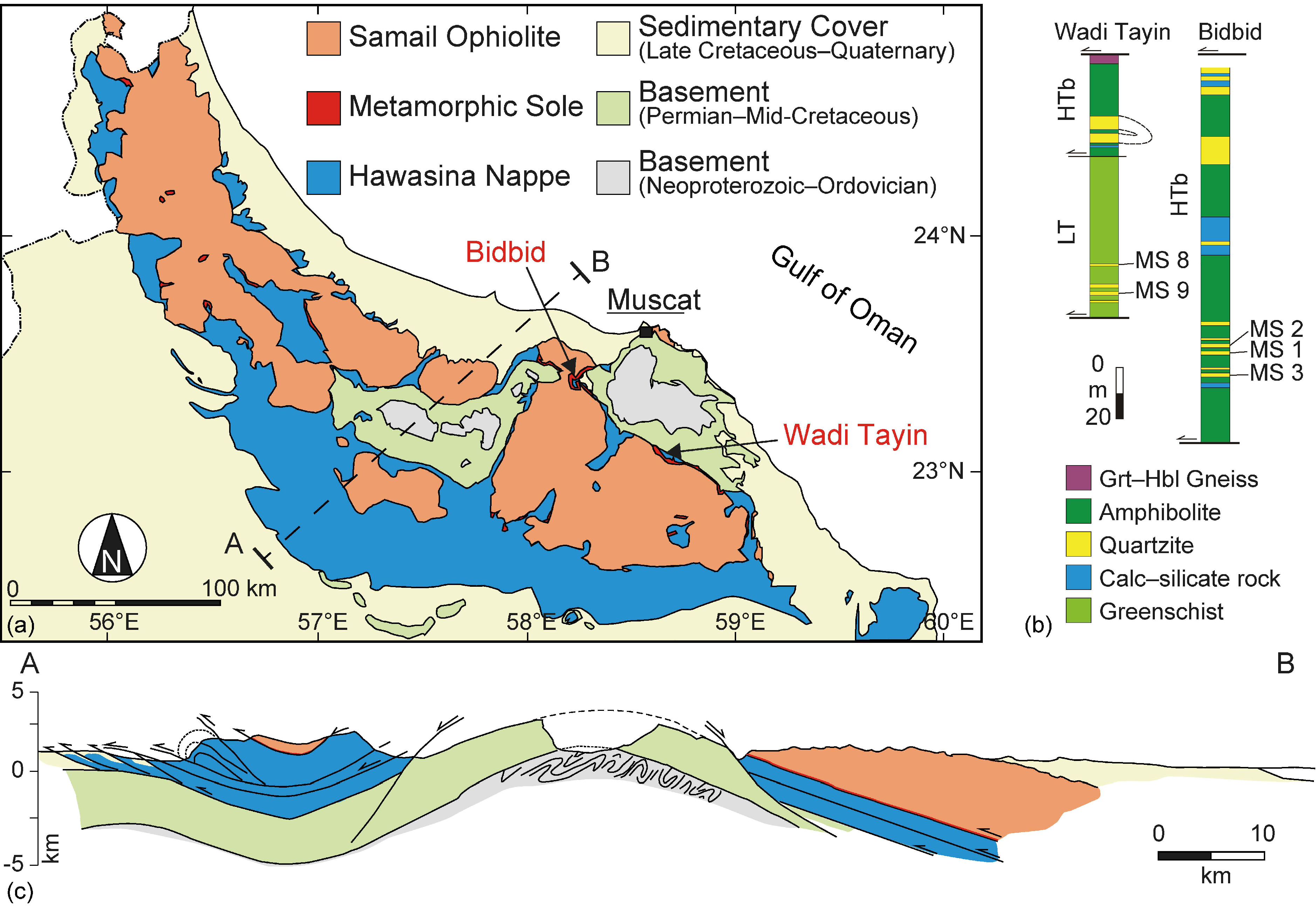
The Oman Mountains comprise the world’s most spectacular and complete ophiolite section (i.e., the Samail ophiolite). The metamorphic sole is an intensely locally deformed more-than-200-m-thick package of amphibolites, greenschists, calc-silicate rocks, and quartzites at the base of the Samail ophiolite (Figure 1). The protoliths of the metamorphic sole were formed between the Permian and the Early Cretaceous as mafic volcanics and pelagic sediments on the floor of the Hawasina Basin, a branch of the Neo-Tethys [1]. During the Late Cretaceous, the ocean floor was buried beneath the ophiolite forming in a supra-subduction zone setting [2] and eventually became partially welded to the base of the ophiolite, forming the metamorphic sole. Both were eventually thrusted onto the Arabian Plate [1,3], here called obduction.
The amphibolites of the metamorphic sole are well documented regarding their petrological, geochronological, and structural features [3,4,5]. Within the laterally discontinuous and locally attenuated sole, the peak metamorphic grade decreases from 850 °C at the top to less than 500 °C at its base [6]. The metamorphic peak ages of the sole rocks scatter from 104 Ma to 94 Ma [7,8], roughly synchronous with the ophiolite crystallization at 98–94 Ma [9]. Kinematic investigations, focused on the upper part of the sole and the contact to the ophiolite, reveal numerous ultramylonitic shear zones [10,11], pointing to ductile high-temperature top-to-the-SSW simple shear [3]. Additionally, texture analyses of amphibolites of the upper part of the metamorphic sole reveal strain accumulation, shape-preferred orientation (SPO), and crystal-preferred orientation (CPO) development during peak metamorphism or shortly thereafter [5] (i.e., during sole accretion). In the footwall of the allochthonous complex, majorly post-obduction deformation processes are recorded, associated with extensional top-to-the-NNE shearing and subsequent doming [12,13]. Thus, the strain during thrusting of the ophiolite complex onto the Arabian Plate had to be accumulated elsewhere.
Figure 1. (a) Simplified geological map of the Oman Mountains in Oman (after [14]); (b) synoptic normal profiles of the metamorphic sole in Wadi Tayin and near the town of Bidbid, with sample locations; (c) cross section through the central part of the Oman Mountains, along the line A–B in the map (modified after [2]).
Geosciences 11 00111 g001
The present study focuses on the deformation record of quartzite mylonites from the high-grade and low-grade parts of the metamorphic sole. Microstructural and textural analyses of quartz and calcite using electron backscatter diffraction (EBSD) and neutron time-of-flight (ToF) technique are used for SPO and CPO analyses to address the following questions: Is the finite strain preserved in these rocks a result of the sole accretion or of the thrusting onto the Arabian Plate or of the crustal-scale extension or a mixture? Are there differences of the particular texture due to different metamorphic overprint or due to differences in strain intensity? Are the quartzites a possible strain accumulator during sole accretion and during thrusting on the Arabian Plate?

2. Geological Setting and Previous Work

The allochthonous units of the Oman Mountains, overlying the autochthonous basement of the Arabian Plate, comprise the Samail ophiolite in the hanging wall, followed by the metamorphic sole and the Haybi and Hawasina nappes in the footwall (Figure 1). The Samail ophiolite complex was formed at roughly 96 Ma (U-Pb zircon ages [7]), most likely in a supra-subduction setting [1,3,9]. The rocks of the metamorphic sole were tectonically eroded from the subducted slab around 94 Ma and subsequently welded to the overriding plate (i.e., the Samail ophiolite) [6,7]. Subsequently, the ophiolite was obducted onto the Arabian Plate [7]. 40Ar/39Ar ages of white mica and biotite of the ophiolite and the metamorphic sole point to the termination of cooling at 90 Ma [15]. Simultaneously, a sequence of Permian to Upper Cretaceous distal deep marine sediments of the Haybi and Hawasina nappes was thrusted directly onto the autochthonous basement of the Arabian Plate [2,16]. The whole crustal section is characterized by an inverse metamorphic and age profile [4,6,8,15,17,18]. The separation of the ophiolite from its metamorphic sole is based on shear zones and the amphibolite geochemistry, which differs significantly from that of the basaltic rocks of the Samail ophiolite and is more similar to that of Triassic and Jurassic basalts of the Haybi and Hawasina units [2].
According to Soret et al. [6], the metamorphic sole can be further subdivided into three metamorphic subunits (in the following, we adopt this classification, Figure 1b). (i) The uppermost amphibolite facies part (HTa) comprises mainly garnet-clinopyroxene amphibolites, which exhibit the highest peak conditions in the sole section. (ii) The upper amphibolite facies part (HTb) consists of plagioclase-rich amphibolites, quartzites, and calc-silicate rocks. (iii) The lower greenschist facies unit (LT) comprises mafic greenschists and metasediments and yields peak metamorphic conditions of 530 °C at 0.5 GPa.
The structural evolution of the metamorphic sole and adjacent units is characterized by accretion, obduction, and several post-obduction deformations, including extensional collapse and doming [2,3,13,19,20]. From the ultramafic ophiolite rocks above the HTa to the LT metacherts at the bottom, the ductile deformation temperature decreases, the simple shear component rotates from top-to-the-SSW to WSW direction, and the amount of pure shear flattening increases [3,21]. The finite strain of the Haybi and Hawasina nappes is the complex result of intense deformation related to both obduction and post-obduction processes (extension and doming [22]). Grobe et al. [12] and Scharf et al. [23] focused on the deformation in the carbonaceous sediments below the Samail ophiolite and its metamorphic sole. In these sediments, ductile-obduction-related deformation plays a minor role. Here, the structural features majorly document the ductile-brittle transition and show extensional top-to-the-NNE shear. Later, doming of these units led to the development of the tectonic windows of Saih Hatat, Jebel Akhdar, and Hawasina [24].
CPO analyses of olivine and orthopyroxene from harzburgites at the base of the ophiolite and quartz from a quartzite in the metamorphic sole (Figure 2) show asymmetric textures, indicating top-to-the-SW simple shear [21]. Recently, more detailed texture analyses by Soret et al. [5] indicated strain accumulation and texture development in amphibolites of the HTa part of the sole during subduction and metamorphic sole accretion.

3. Methods

3.1. Sampling

Five samples were collected from different quartzite layers of the metamorphic sole (Table 1, Figure 1b), three near the town of Bidbid (MS 1–3) and two from Wadi Tayin (MS 8 and 9). Samples MS 1–3 belong to the HTb (i.e., close to the Samail ophiolite). Samples MS 8 and 9 are part of the LT (i.e., close to the Hawasina nappe). Microstructural and textural observations were analyzed in the XZ section of the finite strain ellipsoid (i.e., normal to the foliation and parallel to the stretching lineation).

3.2. Neutron Time-of-Flight Texture Analyses

Neutron ToF measurements were performed on whole-rock sample cubes (~4 × 4 × 4 cm) at the texture diffractometer SKAT at the Frank Laboratory of Neutron Physics at JINR, Dubna, Russia (for instrument specifications, see [25]). The samples were measured in a water moderator mode cycle of the IBR-2M reactor. The step size was 5°, and the measuring time per position was 520–570 s (Table S1). For data clean-up and postprocessing, the MTEX toolbox by Ralf Hielscher was used (http://mtex-toolbox.github.io/, accessed on 25 February 2021, [26,27]). Intensity differences of the measuring positions, originated from detector efficiency differences, the fluctuating reactor power during measuring time, and the sample shape were compensated by normalizing the total intensity per step with its coefficient (deviation from the mean). A baseline calculated from the summarized spectra was used to correct the single spectrum with respect to the neutron energy distribution. D-values, channel position, and absolute and relative intensities were calculated by using the crystal information files of Hazen et al. [28] for quartz and of Markgraf and Reeder [29] for calcite. For the recalculation of pole figures, the relative intensity was used as the superposition factor to separate peaks diffracted by different lattice planes (e.g., {r} and {z} of quartz). The orientation density function (ODF) is based on a single-peak calculation using six to eight peaks (measured pole figures) in the case of quartz and five peaks in the case of calcite (Table S1). During peak selection, attention was paid to keeping the error (L1 error) between the pole figures and ODF as small as possible. The kernel was fixed at a half-width of 7.5° (i.e., 1.5 times the resolution). All pole figures were plotted antipodally in the upper hemisphere and equal area projection. Texture strength is given by the maximum of multiples of random distribution (m.r.d.), texture index (implemented in MTEX), and uniform portion.

3.3. Electron Backscatter Diffraction

EBSD maps were collected with a JEOL JSM-7001F Schottky emission scanning electron microscope at the TU Bergakademie Freiberg, equipped with a Bruker e-Flash high-definition EBSD detector in low vacuum mode, using 2 × 2 or 4 × 4 binning, 15 kV acceleration voltage, a beam current of 15 nA, a frame average of 32.8 ns, and a step size of 3.09 or 6.19 µm (for sample-specific configuration, see Table S2). Because several EBSD software packages use different, not unique coordinate systems [30], the Euler reference system had to be rotated 180° at a fixed sample coordinate system (verified by an U-stage test [31]). In order to remedy the relatively large grain size of the studied samples compared with the narrowness of the measured area due to instrument configuration, several EBSD maps were stitched. This was done manually without taking care of the trapezoidal distortion given by the measurement arrangement. For data correction and processing, the MTEX toolbox was used. All single mis-indexed pixels, pixels with worse properties, such as the number of Kikuchi bands (<6), the band contrast (≤80), and the mean average derivation (≥1.4°), were deleted. To avoid Dauphiné twins, quartz grains were calculated using point group 622 and then transformed back into trigonal point group 321 [32]. Grains were calculated using a threshold of 10° of misorientation. Grains <3 pixels were deleted and reconstructed together with nonindexed pixels. Nonindexed areas smaller than 3 pixels wide were attributed to grains. This avoids holes within grains but keeps the grain expansion. Pole figures were calculated from the orientation distribution functions (ODFs) of the grain modal orientation, one point per grain, plotted antipodally in the upper hemisphere and equal area projection. The kernel half-width was fixed at 7.5 degree. Texture strength is given by maximum pole figure densities (multiples of random distribution) and texture index (implemented in MTEX). For grain shape analyses, grains were smoothed to remove staircase effects, and only grains larger than 20 pixels were used. This ensured that we analyzed deformed grains, not new grown ones. Grain size is represented by the area equivalent diameter of a certain grain. Grain long-axis calculation was done by using the orthogonal of the grain short axis to avoid tripping long axis in brick-shaped grains. The aspect ratio is the ratio between the long and the short axis. The shape factor represents the perimeter divided by the perimeter of the area-equivalent ellipse (i.e., an expression of how lobate the grain boundary is).
To compare intragranular deformation the grain orientation spread and the grain kernel average misorientation were used. The grain orientation spread represents the mean of all misorientation angles (of all grain pixels) to the grain modal orientation, whereas the grain kernel average misorientation is defined as the mean of all kernel average misorientations per grain. The kernel average misorientation is the local grain misorientation (i.e., this method is more sensitive to subgrain boundaries than grain orientation spread). Of the samples measured with a step size of 3.09 µm, only every second step was used for grain orientation spread and grain kernel average misorientation calculation.

4. Results

4.1. Sample Description and (Micro-) Structures

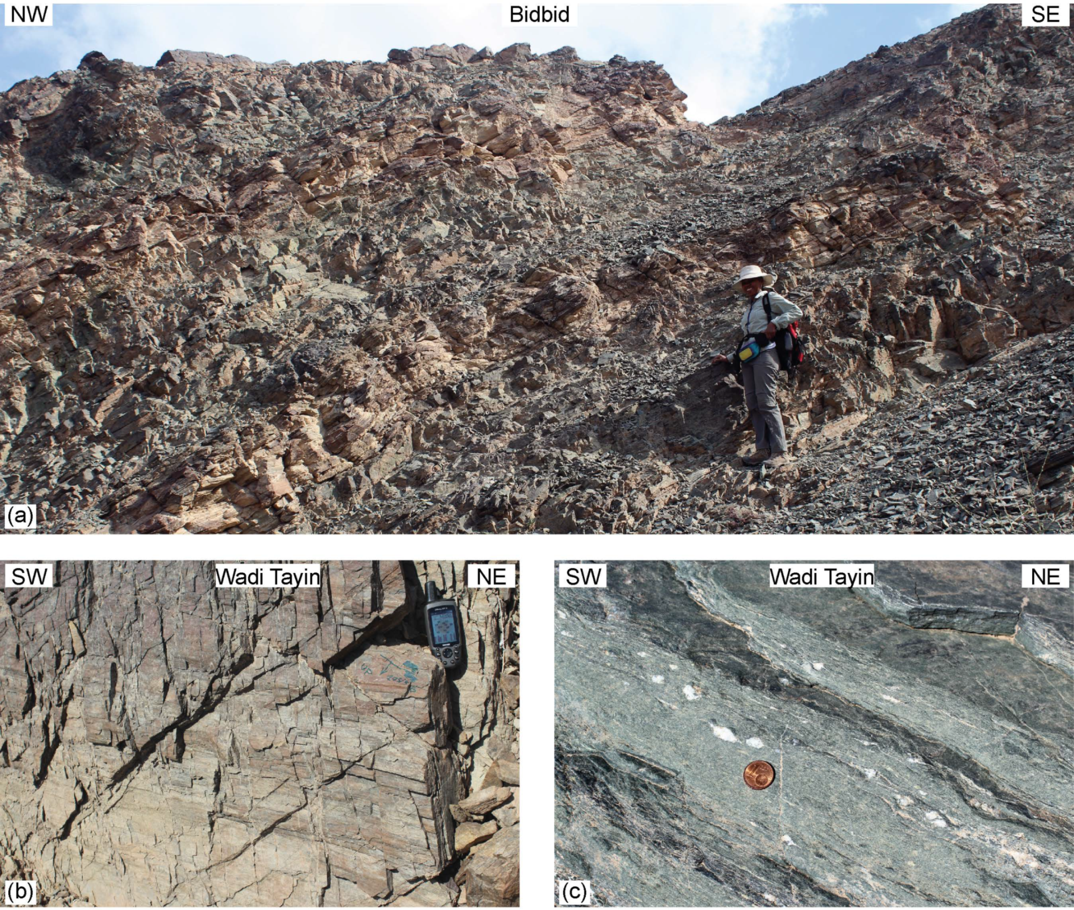
The quartzites MS 1–3 that belong to the HTb part of the metamorphic sole (Figure 1b and Figure 3a) represent fine-grained LS tectonites with NNE-SSW oriented stretching lineation and a main foliation dipping of ~55° towards WNW. The fine-grained LS tectonites from the LT part of the metamorphic sole (MS 8 and 9) show a steep foliation dipping towards the NE and strong stretching lineations trending NE-SW to E-W (Figure 3b). Plagioclase σ-clasts in the adjacent metabasites point to SW-directed sense of shear (Figure 3c).
The sampling site of MS 8 and 9 represents a tectonically strongly thinned part of the metamorphic sole. Samples MS 1, 8, and 9 represent quartzite with less than 5% of calcite, whereas the amount of calcite is much higher in sample MS 2 and exceeds 50% in sample MS 3.
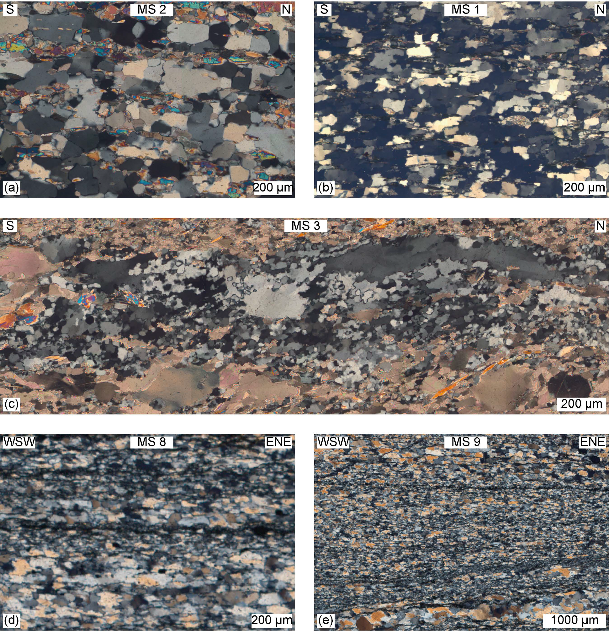
Both quartz and calcite are characterized by strong dynamic recrystallization in all samples (Figure 4). For quartz, the complete field of dynamic recrystallization processes, from grain boundary migration (GBM) to subgrain rotation (SGR) and bulge nucleation (BLG), is observed. The samples mainly differ in the varying dominance and activity, simultaneously or successively, of the individual recrystallization processes (Table 1). In general, SGR plays a more significant role in the LT part, and BLG is most abundant in sample MS 3. Strong SPO development due to SGR or pinning of a secondary phase (e.g., calcite) is partly attenuated by lobate grain boundaries, especially in the HTb part. The predominant recrystallization structure of calcite (MS 3) is a result of GBM, overprinted by BLG. The calcite in sample MS 2 is restricted to grain interstices of quartz, and thus, the recrystallization mechanisms are almost prevented or cannot be observed.

4.2. Quartz

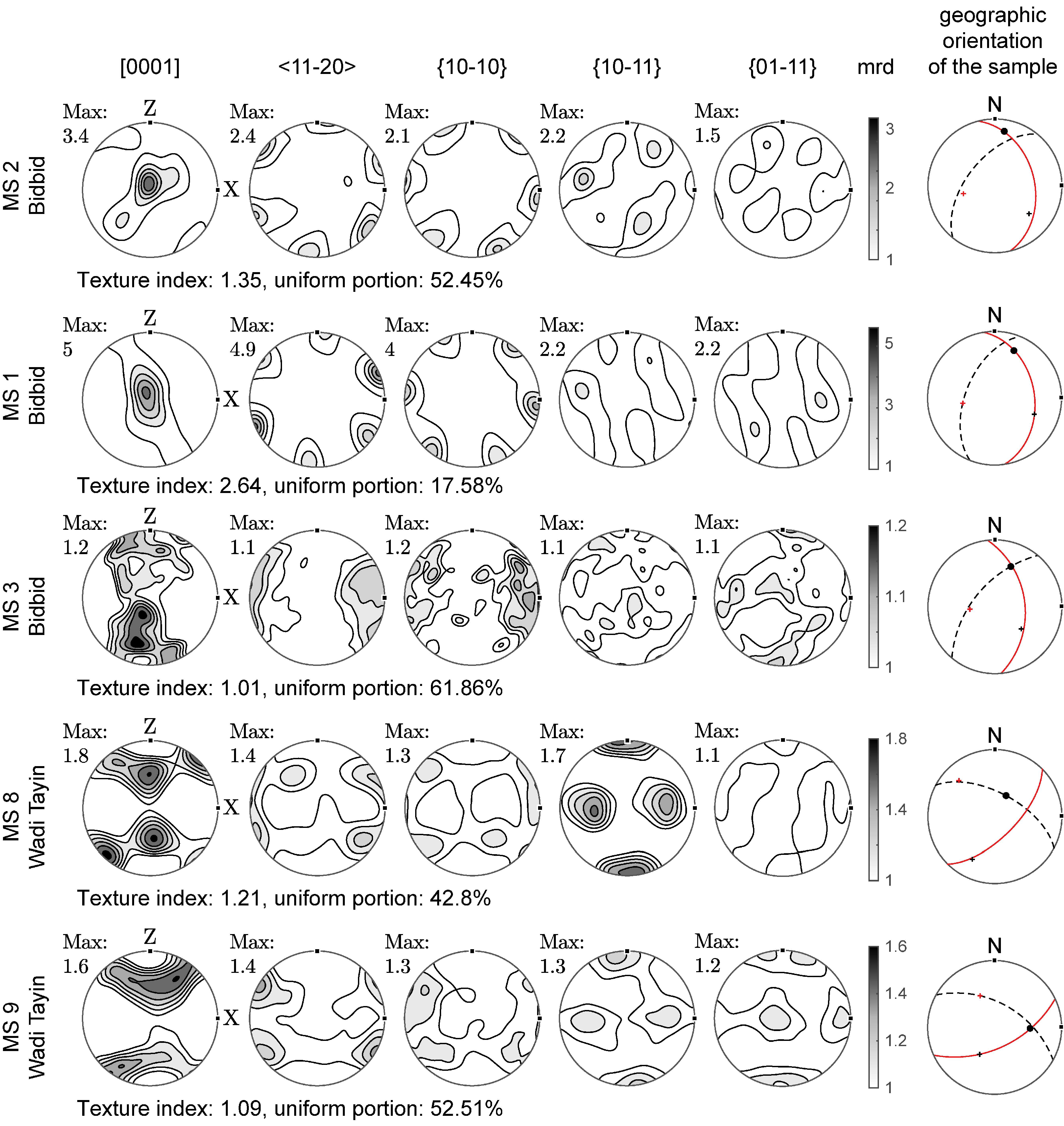
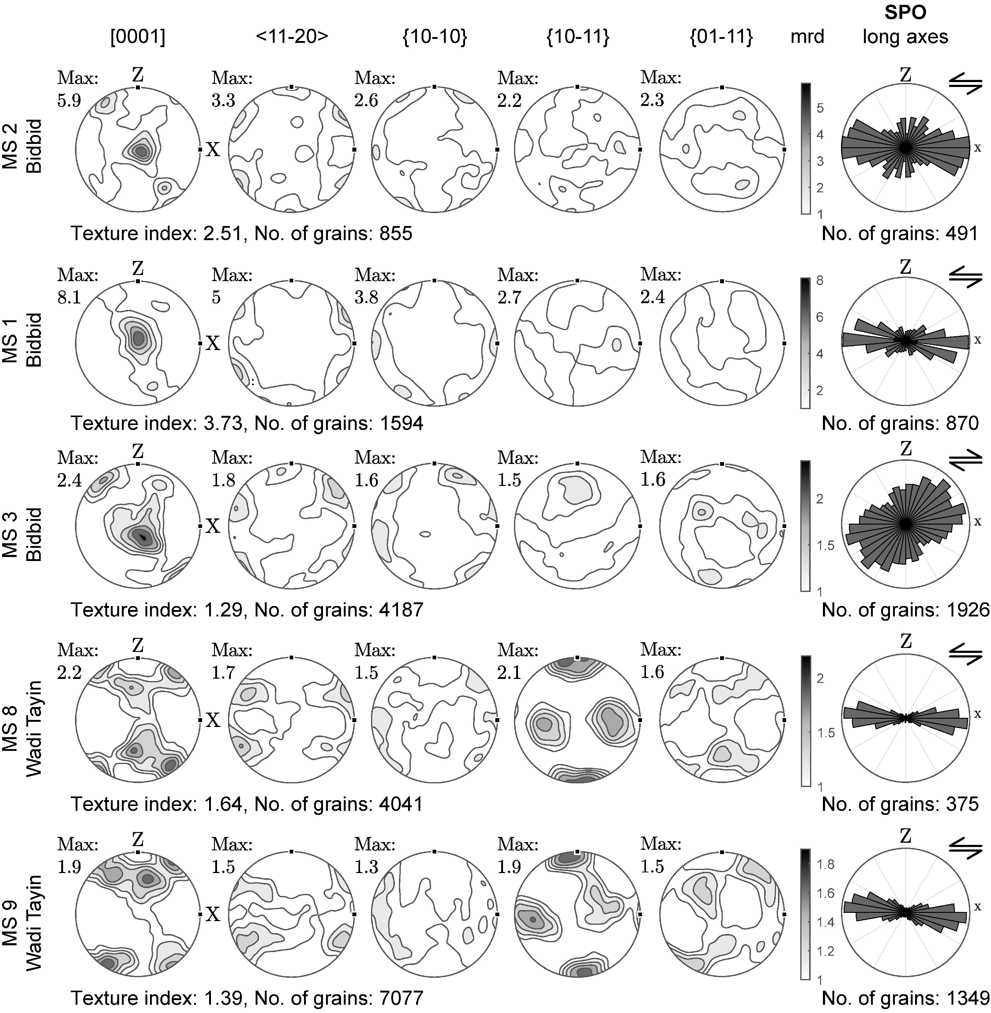
The geometry of quartz pole figures is highly variable over the profile of the metamorphic sole. Neutron ToF bulk textures and EBSD local textures reveal two main types of pole figure skeletons (Figure 5 and Figure 6). (i) In the HTb part (MS 1 and 2), [c]-axis pole figures show an elongated maximum in the center, parallel to the structural y direction ([c]-in-Y texture), overlying a weak single or crossed girdle. Further, the <a>-axes, {m}, {r}, and {z}-poles show a tendency towards a single crystal-like texture. (ii) In the LT part (MS 9), a small girdle distribution of the [c]-axes, <a>-axes, and {m}-poles around structural Z is associated with strong {r} maximum in Z ({r}-in-Z textures). Texture transition from {r}-in-Z textures to [c]-in-Y textures results in [c]-axis distributions characterized by small girdle distributions with local maxima (MS 8—ToF) and crossed girdles (MS 8—EBSD). The <a>-axis distribution changes from a small girdle distribution with two maxima at the periphery (±15° to the structural X direction) to three maxima at the periphery with one stronger maximum oriented approximately parallel to X with an anticlockwise component of rotation of ~10° (pole figure view, Figure 6). This in turn indicates top-to-the-SSW sense of shear (for MS 1–3).
The maximum of the grain long-axis distribution, oriented with a clockwise component of rotation of 5°–10° with respect to the foliation, points to top SSW (MS 1 and 2) and SW (MS 8 and 9) sense of shear. For sample MS 3, the quartz long-axis distribution is significantly weaker and points to a top-to-NNE sense of shear (i.e., in the opposite direction to that indicated by the <a>-axes).
Considering the grain shape (Figure 7) (i.e., grain size, aspect ratio, and shape factor), samples MS 1 and 2 and samples MS 8 and 9 are similar. The latter are characterized by smaller grain sizes with a narrow range, slightly larger aspect ratios, and clearly lower shape factors. Thus, the quartz grains of MS 8 and 9 can be described as elongated equal-size grains with smooth boundaries, which is indicative of SGR. In contrast, the quartz grains of MS 1 and 2 yield different grain sizes, a less elongated habit, and more irregular grain boundaries, which is indicative of GBM. The shape analyses of MS 3 show the lowest aspect ratio and shape factor and point to more rounded smaller grains.
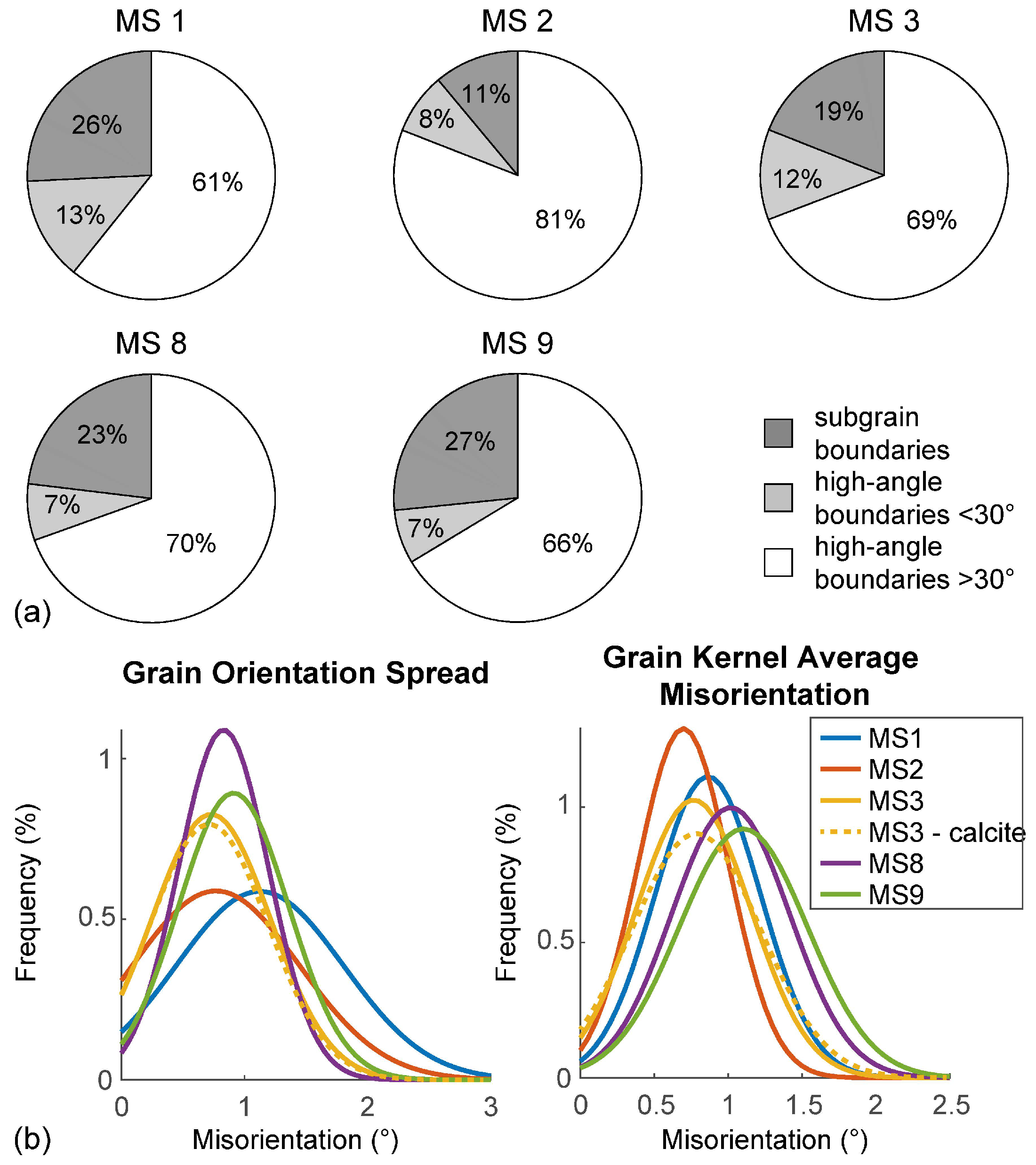
The proportion of low-angle grain boundaries (2°–10°) in comparison with high-angle grain boundaries varies from 11% to 27% (Figure 8a). Samples MS 1, 8, and 9 have higher percentage of subgrain boundaries (i.e., those point to higher intragranular deformation). Characterizing the internal grain deformation, the grain orientation spread and the grain kernel average misorientation were measured (Figure 8b). Grain orientation spread exhibits a wide distribution for MS 1 and 2, but narrow distributions for samples MS 8, 9, and 3 with fewer grains showing high values. In contrast, the grain kernel average misorientation has comparable distribution widths for all samples, with the highest values for MS 8 and 9, followed by MS 1. Thus, the dislocation density in the LT part is higher and more strongly localized (e.g., forming subgrain boundaries).

4.3. Calcite

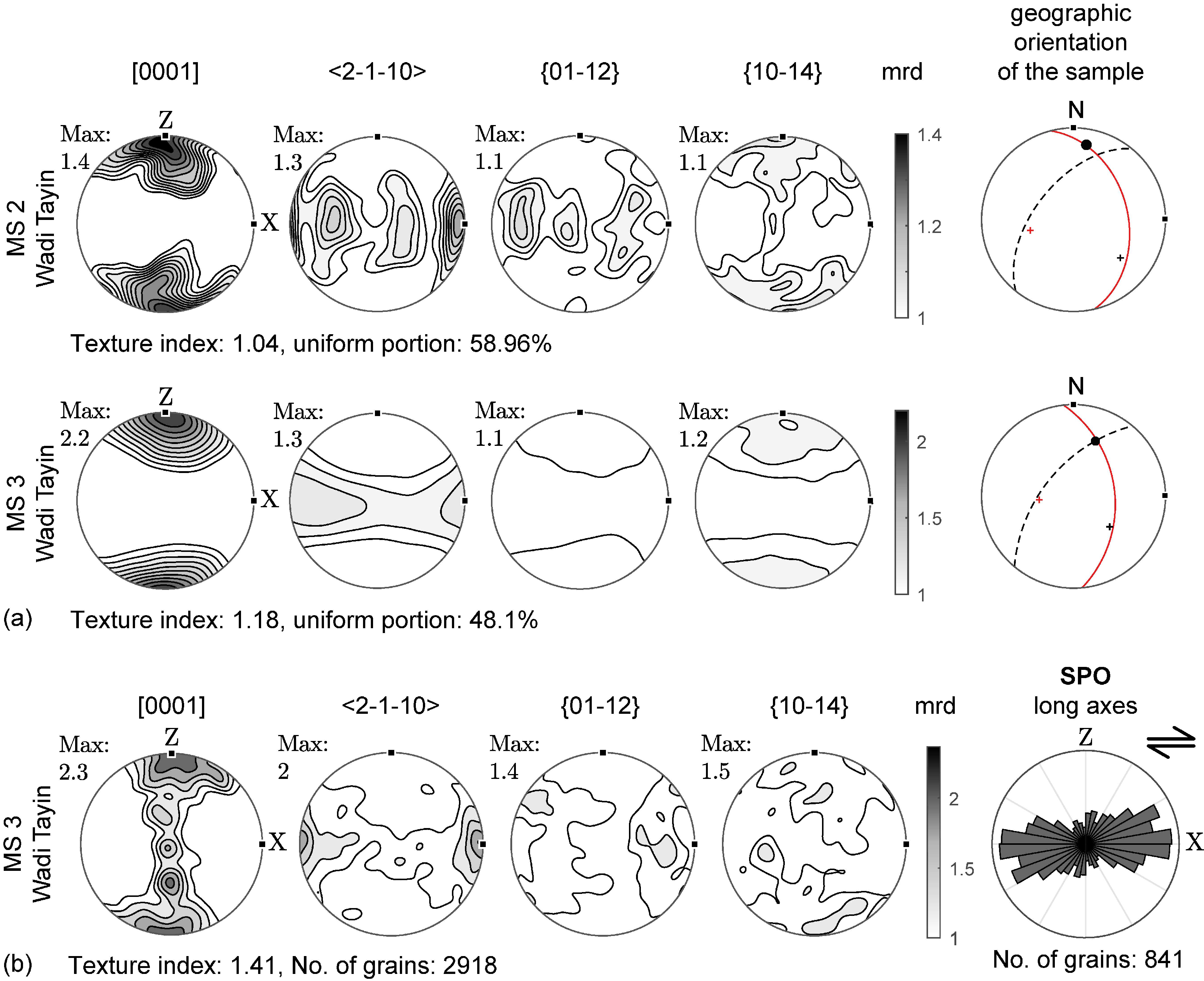
Calcite CPO was measured by ToF from two samples (MS 2 and 3) and by EBSD from one sample (MS 3). The pole figures of the c [0001] and a <2-1-10> axes and the f {01-12} and r {10-14} poles are shown in Figure 9 together with the shape long-axis distribution of the calcite grains of MS 3.
The whole-rock ToF texture of both samples is characterized by [c]-axes pointing to a maximum perpendicular to the main foliation (shear plane), varying in strength. The <a>-axes are concentrated along a girdle, parallel to the foliation, with a maximum in the X direction. The {f}-poles define a weak girdle distribution, and the {r}-poles are concentrated normally to the foliation. The strength of the latter two pole figures is lower than that for [c]- and <a>-axes. The local texture obtained from the EBSD measurements shows a symmetric single girdle [c]-axis distribution perpendicular to the foliation, with a maximum at the periphery. The <a>-axes and the {r}-poles are equal to the whole-rock texture. The {f}-poles show weak small girdle distributions around X.
The calcite grain long-axis maximum of MS 3 is oriented approximately within the foliation with an anticlockwise component of rotation of 5°, corresponding to top-to-the-NNE sense of shear. The grain shape, grain orientation spread, and grain kernel average misorientation of calcite is similar to that of the quartz grains in this sample (MS 3).

5. Discussion

5.1. Quartz Microstructure and Texture-Forming Process

Microstructural observation and grain shape analysis indicate GBM and SGR as the predominant recrystallization mechanisms for the HTb samples (MS 1 and 2) and for the LT samples (MS 8 and 9), respectively. However, the aspect ratio and strong SPO of MS 1 (and MS 2) are quite atypical for GBM. Therefore, the question is, what defines the SPO in these samples, GBM and pinning of the quartz boundary or SGR?
Sample MS 2 shows calcite grains enclosed by quartz grains (i.e., pinning to secondary phases is less important (cf. GBM II of [33])). However, in MS 1, such microstructures are less observed or less evident. Since grain shape could be affected by pinning of grain boundaries by a secondary phase, intragranular deformation analysis can provide better indication of the active recrystallization mechanism affecting a particular grain. GBM-dominated samples should have a higher amount of grain orientation spread because the grain-free energy cannot be reduced at small-angle grain boundaries. Concurrently, there should be a small amount of low-angle grain boundaries. Both effects are true for MS 2. In contrast, MS 1 shows a lot of low-angle grain boundaries, but also high grain orientation spread. Thus, in MS 1, the high grain-free energy is for some reason not reduced at the low-angle grain boundaries. Hence, we interpret the low-angle grain boundaries and the SPO as a relic of previous recrystallization by SGR.
Nevertheless, GBM and SGR are indicative of the last recrystallization mechanisms in quartzites of the HTb and LT part, respectively. Strong [c]-in-Y texture is concomitant with predominant GBM (HTb), and {r}-in-Z texture is associated with thoroughgoing SGR recrystallization (LT). This agrees with Stipp et al. [33], who suggested that different recrystallization mechanisms result in different textures and that GBM leads to [c]-in-Y textures with a tendency towards single crystal-like textures. Texture transitions from [c]-in-Y textures to {r}-in-Z texture are also reported from other shear zones [28,31,34]. Explanations of texture-forming processes and recrystallization mode are varied and include the change of rheological behavior due to temperature or strain variations [35,36,37]. Therefore, [c]-in-Y texture and GBM are a result of higher temperatures or lower strain rates compared with {r}-in-Z textures and SGR. The geological setting provides hints for both. The first explanation is encouraged by an inverse temperature gradient, which is a result of advective heat transfer due to the overlying ophiolite [4]. However, the temperature in the upper part of the sole decreases first rapidly and then slowly over time [15], which suggests an early temperature equalization over the entire sole section. As further indicated for the HTb part, where GBM overprints SGR recrystallization and later BLG overprints GBM (MS 3), different deformation steps are present. Linking them to different metamorphic conditions would mean an increase in temperature during the transition from SGR to GBM. The juxtaposition of the different parts of the sole and the ophiolite takes place after reaching the peak metamorphic conditions [3,18]. In general, the preserved quartz CPO and SPO in nature are a result of ductile deformation at temperatures equal to or below 700 °C [38]. After peak temperature conditions of 850 °C, there is no hint for a reheating on the retrograde path [6]. Thus, we interpret the transition from SGR to GBM in the HTb part to be caused by strain rate decrease during obduction, concomitant with CPO modification from a c-axis girdle distribution to strong point maxima in Y. Contemporaneously, the strain rate in the tectonically strongly thinned part of the LT part in Wadi Tayin remains high. As it is common in shear zones, strain partitioning is indicated for the LT part by the quartzite sample of Boudier and Coleman [21] (see Figure 2).
Certainly, the BLG recrystallization in MS 3 is a result of a later deformation under low temperature and strain conditions, presumably concomitant with the calcite texture development. The reason for the exclusive occurrence of BLG recrystallization in quartz in a calcite-rich sample can be seen by the rheological weakness of calcite at high temperatures, while quartz is strong and minor recrystallization only occurs at lower temperatures.

5.2. Tectonic Implications: Type of Strain and Sense of Shear

The quartz <a>-axis orientation, anticlockwise rotation out of the X direction, and the grain long-axis distribution, clockwise rotation out of the X direction, point to top-to-the-SSW to SW sense of shear. The variation from SSW in the HTb to SW in the LT corroborates former observations [3,21]. The long-axis distribution in MS 1 and 2 is the result of the early SGR rather than the overprinting GBM. Further, the texture and ductile microstructural evolution of the amphibolites are interpreted to be related to subduction and sole accretion [5], accompanying a shear sense top to SSW [3]. Thus, the shear direction rotates from S(SW) to (W)SW through time. According to Morris et al. [39], the arc-trench system and, thus, the ophiolite underwent an intraoceanic clockwise rotation of 90° before and during its obduction. At the onset of the obduction (ongoing slab rollback) associated with the metamorphic sole accretion, the subduction zone was dipping towards N(NE), whereas the final emplacement on the Arabian Plate occurred in the (W)SW direction. This in turn indicates a propagation of strain accumulation downwards during ongoing obduction and thrusting onto the Arabian Plate (i.e., moving from rheologically hardened to weaker rock material).
The shape and symmetry of texture skeletons provide hints on the strain mode during quartz deformation [35,36]. Applied to the presented samples, this means non-coaxial deformation under prolate to plane strain for MS 1 and 2 (relic single and crossed girdle distribution of the c-axes; HTb) and nearly coaxial deformation under plane to oblate strain for MS 8 and 9 (LT). The increase of the amount of coaxial deformation and oblate strain with depth can be attributed to the loading of the ophiolite [3], which is higher during the thrusting onto the Arabian Plate than in the subduction zone.
The quartz texture and microstructure obtained in MS 3 are the most complex in our study. The microstructural development could be divided into two parts, a former GBM and SGR recrystallization and a more recent BLG nucleation. The EBSD local texture, which was measured in an area exhibiting several relict GBM and SGR grains, is comparable to other quartzites in HTb and points to non-coaxial deformation with top-to-the-SSW shear. In contrast, the quartz whole-rock texture (ToF) and the calcite texture point to low temperatures near the ductile-brittle transition and coaxial deformation under plane to oblate strain. The obtained top-to-the-NNE shear sense from long-axis distributions of quartz and calcite grains is interpreted to be part of the late low-temperature deformation. NNE-directed simple shear tectonics in combination with extensional tectonics is described for the underlying Haybi and Hawasina nappes and the autochthonous carbonate platform of the Arabian Plate [12,22,23].

6. Conclusions

Detailed microstructural and textural analyses of the quartzites of the metamorphic sole allow us to differentiate two main deformation steps (i.e., sole accretion to thrusting onto the Arabian Plate and post-obduction deformation). In particular, the main conclusions that can be drawn are the following:
  • Differences in texture and microstructure within the quartzites of the metamorphic sole result from strain variations rather than temperature differences. Additionally, GBM in the HTb part and SGR in the LT part were likely contemporaneous. Thus, during quartz texture development, there is a regional (HTb vs. LT part) and probably local strain partitioning;
  • The quartz recrystallization and texture development in the HTb and LT part of the metamorphic sole occurred during the sole accretion or thrusting on the Arabian Plate (except MS 3). SGR is the most important recrystallization process for microstructural fabric development. In the upper part, SGR gets overprinted by GBM, while in the lower part, SGR is still active. Thus, grain long-axis distribution from different crustal depths is frozen in the upper and lower parts of the metamorphic sole. We conclude that the differences in simple shear direction correlate to ophiolite rotation during obduction (i.e., older SSW direction in the HTb part and younger SW direction in the LT part). Additionally, it is proposed that the main strain accumulation during ongoing obduction and thrusting onto the Arabian Plate propagates towards the footwall, away from the base of the ophiolite;
  • BLG nucleation, quartz whole-rock texture, and quartz SPO of MS 3 and calcite CPO and SPO point to low-temperature coaxial deformation with a minor simple shear component, indicating top-to-the-NNE kinematics. These late texture developments of the metasediments of the metamorphic sole correlate with the post-obduction extensional tectonic event, which is predominantly documented in the underlying autochthonous units.

Supplementary Materials

The following are available online at https://www.mdpi.com/2076-3263/11/3/111/s1: Table S1: ToF, Table S2: EBSD, all raw data.

Author Contributions

Conceptualization, P.H. and W.B.; sample analysis, P.H.; field investigation, W.B.; data curation, P.H.; writing—original draft preparation, P.H. and W.B.; writing—review and editing, P.H. and W.B. All authors have read and agreed to the published version of the manuscript.

Funding

This research received no external funding.

Institutional Review Board Statement

Not applicable.

Informed Consent Statement

Not applicable.

Data Availability Statement

All data are available in the Supplementary Materials.

Acknowledgments

The suggestions of three anonymous reviewers are gratefully acknowledged; their comments helped to improve the manuscript significantly. We are also grateful to the Frank Laboratory of Neutron Physics (FLNP) at Dubna (Russia) for support in the texture measurements.

Conflicts of Interest

The authors declare no conflict of interest.

References

  1. Searle, M.P.; Cox, J. Subduction zone metamorphism during formation and emplacement of the Semail ophiolite in the Oman Mountains. Geol. Mag. 2002, 139, 241–255. [Google Scholar] [CrossRef]
  2. Searle, M.P. Structural geometry, style and timing of deformation in the Hawasina Window, Al Jabal al Akhdar and Saih Hatat culminations, Oman Mountains. GeoArabia 2007, 12, 99–130. [Google Scholar]
  3. Cowan, R.; Searle, M.; Waters, D. Structure of the metamorphic sole to the Oman ophiolite, Sumeini Window and Wadi Tayyin: Implications for ophiolite obduction processes. Geol. Soc. Spec. Publ. 2014, 392, 155–175. [Google Scholar] [CrossRef]
  4. Hacker, B.; Mosenfelder, J. Metamorphism and deformation along the emplacement thrust of the Samail ophiolite. Oman. Earth Planet. Sci. Lett. 1996, 144, 435–451. [Google Scholar] [CrossRef]
  5. Soret, M.; Agard, P.; Ildefonse, B.; Dubacq, B.; Prigent, C.; Rosenberg, C. Deformation mechanisms in mafic amphibolites and granulites: Record from the Semail metamorphic sole during subduction infancy. Solid Earth 2019, 10, 1733–1755. [Google Scholar] [CrossRef] [Green Version]
  6. Soret, M.; Agard, P.; Dubacq, B.; Plunder, A.; Yamato, P. Petrological evidence for stepwise accretion of metamorphic soles during subduction infancy (Semail ophiolite, Oman and UAE). J. Metamorph. Geol. 2017, 35, 1051–1080. [Google Scholar] [CrossRef]
  7. Rioux, M.; Garber, J.; Bauer, A.; Bowring, S.; Searle, M.; Kelemen, P.; Hacker, B. Synchronous formation of the metamorphic sole and igneous crust of the Semail ophiolite: New constraints on the tectonic evolution during ophiolite formation from high-precision U-Pb zircon geochronology. Earth Planet. Sci. Lett. 2016, 451, 185–195. [Google Scholar] [CrossRef] [Green Version]
  8. Guilmette, C.; Smit, M.A.; van Hinsbergen, D.J.J.; Gürer, D.; Corfu, F.; Charette, B.; Maffione, M.; Rabeau, O.; Savard, D. Forced subduction initiation recorded in the sole and crust of the Semail Ophiolite of Oman. Nat. Geosci. 2018, 11, 688–695. [Google Scholar] [CrossRef]
  9. Rioux, M.; Bowring, S.; Kelemen, P.; Gordon, S.; Miller, R.; Dudás, F. Tectonic development of the Samail ophiolite: High-precision U-Pb zircon geochronology and Sm-Nd isotopic constraints on crustal growth and emplacement. J. Geophys. Res. Solid Earth 2013, 118, 2085–2101. [Google Scholar] [CrossRef] [Green Version]
  10. Boudier, F.; Ceuleneer, G.; Nicolas, A. Shear zones, thrusts and related magmatism in the Oman ophiolite: Initiation of thrusting on an oceanic ridge. Tectonophysics 1988, 151, 275–296. [Google Scholar] [CrossRef]
  11. Boudier, F.; Nicolas, A.; Bouchez, J. Kinematics of oceanic thrusting and subduction from basal sections of ophiolites. Nature 1982, 296, 825–828. [Google Scholar] [CrossRef]
  12. Grobe, A.; Virgo, S.; Von Hagke, C.; Urai, J.; Littke, R. Multiphase structural evolution of a continental margin during obduction orogeny: Insights from the Jebel Akhdar Dome, Oman Mountains. Tectonics 2018, 37, 888–913. [Google Scholar] [CrossRef]
  13. Mattern, F.; Scharf, A. Postobductional extension along and within the Frontal Range of the Eastern Oman Mountains. J. Asian Earth Sci. 2018, 154, 369–385. [Google Scholar] [CrossRef]
  14. Le Métour, J.; Platel, J.P.; Béchennec, F.; Berthiaux, A.; Chevrel, S.; Dubreuilh, J.; Roger, J.; Wyns, R. Geological Map of Oman, Scale 1:1,000,000; Directorate General of Minerals, Oman Ministry of Petroleum and Minerals: Muscat, Oman, 1993. [Google Scholar]
  15. Hacker, B.R.; Mosenfelder, J.L.; Gnos, E. Rapid emplacement of the Oman ophiolite: Thermal and geochronologic constraints. Tectonics 1996, 15, 1230–1247. [Google Scholar] [CrossRef] [Green Version]
  16. Blechschmidt, I.; Dumitrica, P.; Mater, A.; Krystyn, L.; Peters, T. Stratigraphic architecture of the northern Oman continental margin—Mesozoic Hamrat Duru Group, Hawasina complex, Oman. GeoArabia 2004, 9, 81–132. [Google Scholar]
  17. Agard, P.; Searle, M.P.; Alsop, G.I.; Dubacq, B. Crustal stacking and expulsion tectonics during continental subduction: P-T deformation constraints from Oman. Tectonics 2010, 29, 1–19. [Google Scholar] [CrossRef]
  18. Garber, J.M.; Rioux, M.; Kylander-Clark, A.R.; Hacker, B.R.; Vervoort, J.D.; Searle, M.P. Petrochronology of Wadi Tayin metamorphic sole metasediment, with implications for the thermal and tectonic evolution of the Samail Ophiolite (Oman/UAE). Tectonics 2020, 39. [Google Scholar] [CrossRef]
  19. Miller, J.M.; Gregory, R.; Gray, D.; Foster, D.A. Geological and geochronological constraints on the exhumation of a high-pressure metamorphic terrane, Oman. Geol. Soc. Spec. Publ. 1999, 154, 241–260. [Google Scholar] [CrossRef]
  20. Csontos, L.; Pocsai, T.; Sasvári, Á.; Palotai, M.; Árgyelán-Bagoly, G.; Fodor, L.I.; Magyari, Á.; Al-Wardi, M. Structural evolution of the Hawasina Window, Oman Mountains. GeoArabia 2010, 15, 85–124. [Google Scholar]
  21. Boudier, F.; Coleman, R.G. Cross section through the peridotite in the Samail ophiolite, southeastern Oman Mountains. J. Geophys. Res. Solid Earth 1981, 86, 2573–2592. [Google Scholar] [CrossRef]
  22. Béchennec, F.; Le Metour, J.; Rabu, D.; Bourdillon-de-Grissac, C.; De Wever, P.; Beurrier, M.; Villey, M. The Hawasina Nappes: Stratigraphy, palaeogeography and structural evolution of a fragment of the south-Tethyan passive continental margin. Geol. Soc. Spec. Publ. 1990, 49, 213–223. [Google Scholar] [CrossRef]
  23. Scharf, A.; Mattern, F.; Pracejus, B. Two new microscopic ductile kinematic indicators from the Oman Mountains. J. Struct. Geol. 2019, 119, 107–117. [Google Scholar] [CrossRef]
  24. Mann, A.; Hanna, S.S.; Nolan, S.C. The post-Campanian tectonic evolution of the Central Oman Mountains: Tertiary extension of the Eastern Arabian Margin. Geol. Soc. Spec. Publ. 1990, 49, 549–563. [Google Scholar] [CrossRef]
  25. Keppler, R.; Ullemeyer, K.; Behrmann, J.H.; Stipp, M. Potential of full pattern fit methods for the texture analysis of geological materials: Implications from texture measurements at the recently upgraded neutron time-of-flight diffractometer SKAT. J. Appl. Crystallogr. 2014, 47, 1520–1534. [Google Scholar] [CrossRef]
  26. Hielscher, R.; Schaeben, H. Multi-scale texture modeling. Math. Geosci. 2008, 40, 63–82. [Google Scholar] [CrossRef]
  27. Hielscher, R.; Schaeben, H. A novel pole figure inversion method: Specification of the MTEX algorithm. J. Appl. Crystallogr. 2008, 41, 1024–1037. [Google Scholar] [CrossRef]
  28. Hazen, R.; Finger, L.; Hemley, R.; Mao, H. High-pressure crystal chemistry and amorphization of α-quartz. Solid State Commun. 1989, 72, 507–511. [Google Scholar] [CrossRef]
  29. Markgraf, S.A.; Reeder, R.J. High-temperature structure refinements of calcite and magnesite. Am. Mineral. 1985, 70, 590–600. [Google Scholar]
  30. Britton, T.; Jiang, J.; Guo, Y.; Vilalta-Clemente, A.; Wallis, D.; Hansen, L.; Winkelmann, A.; Wilkinson, A. Tutorial: Crystal orientations and EBSD—Or which way is up? Mater. Charact. 2016, 117, 113–126. [Google Scholar] [CrossRef] [Green Version]
  31. Hallas, P. Tectonics of an Intracontinental Exhumation Channel in the Erzgebirge, Central Europe. Ph.D. Thesis, TU Bergakademie Freiberg, Freiberg, Germany, 2020. [Google Scholar]
  32. Kilian, R.; Heilbronner, R. Analysis of crystallographic preferred orientations of experimentally deformed Black Hills Quartzite. Solid Earth 2017, 8, 1095–1117. [Google Scholar] [CrossRef] [Green Version]
  33. Stipp, M.; Stünitz, H.; Heilbronner, R.; Schmid, S.M. The eastern Tonale fault zone: A ‘natural laboratory’ for crystal plastic deformation of quartz over a temperature range from 250 to 700 °C. J. Struct. Geol. 2002, 24, 1861–1884. [Google Scholar] [CrossRef]
  34. Wenk, H.-R.; Yu, R.; Vogel, S.; Vasin, R. Preferred orientation of quartz in metamorphic rocks from the Bergell Alps. Minerals 2019, 9, 277. [Google Scholar] [CrossRef] [Green Version]
  35. Lister, G.; Hobbs, B. The simulation of fabric development during plastic deformation and its application to quartzite: The influence of deformation history. J. Struct. Geol. 1980, 2, 355–370. [Google Scholar] [CrossRef]
  36. Schmid, S.; Casey, M. Complete fabric analysis of some commonly observed quartz c-axis patterns. Geophys. Monogr. 1986, 36, 263–286. [Google Scholar]
  37. Law, R.D. Deformation thermometry based on quartz c-axis fabrics and recrystallization microstructures: A review. J. Struct. Geol. 2014, 66, 129–161. [Google Scholar] [CrossRef]
  38. Tokle, L.; Hirth, G.; Behr, W.M. Flow laws and fabric transitions in wet quartzite. Earth Planet. Sci. Lett. 2019, 505, 152–161. [Google Scholar] [CrossRef]
  39. Morris, A.; Meyer, M.; Anderson, M.W.; MacLeod, C.J. Clockwise rotation of the entire Oman ophiolite occurred in a suprasubduction zone setting. Geology 2016, 44, 1055–1058. [Google Scholar] [CrossRef]
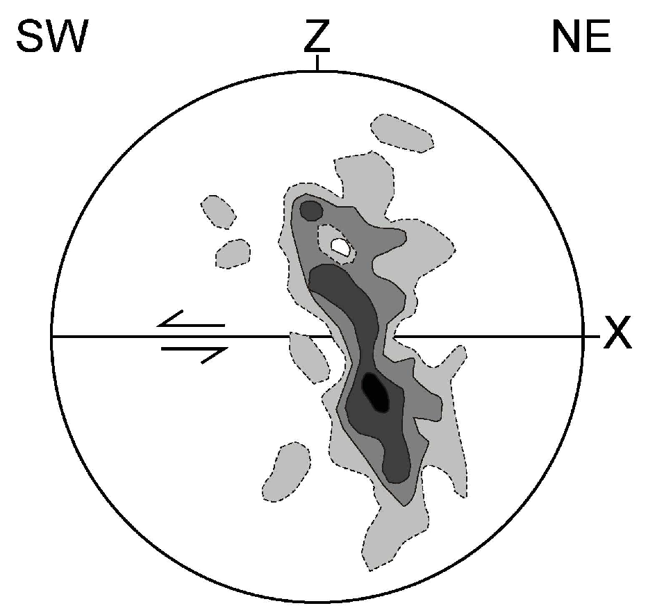
Figure 2. Quartz [c]-axis pole figure (100 grains) showing an asymmetric single girdle, interpreted as top-to-SW sense of shear, Wadi Tayin (modified after [21]).
Geosciences 11 00111 g002
Figure 3. (a) The sampling site of MS 1 and 2 near Bidbid (N 23°25′24.6″, E 58°8′32.0″). Interlayering of quartzite (light rocks) and amphibolite (dark rocks); (b) mylonitic greenschist with asymmetric σ-clasts, indicating top-to-the-southwest sense of shear, approximately 500 m above the sampling site of MS 8, Wadi Tayin; (c) quartzite of the sampling site of MS 8 (N 23°3′53.9″, E 58°35′49.9″, Wadi Tayin) characterized by steep mylonitic foliation (028/68) and strong stretching lineation (L 028/61), indicating a high amount of simple shear.
Geosciences 11 00111 g003
Figure 4. (a) Quartz microstructures affected by dynamic recrystallization. MS 2 shows large grains with lobate grain boundaries indicative of predominant GBM; (b) MS 1 shows brick-shaped grains with highly lobate boundaries (GBM), strong SPO due to SGR or pinning of quartz boundaries by a secondary phase; (c) Sample MS 3 with the highest calcite content is characterized by large leftover grains, presumably signs of an older deformation with predominant GBM, the dominant quartz recrystallization being due to BLG; (d,e) Microfabric of MS 8 and 9 resulting from thoroughgoing SGR, characterized by smaller grain size than (a,b) and brick-shaped grains with strong SPO.
Geosciences 11 00111 g004
Figure 5. Recalculated quartz pole figure results from time-of-flight (ToF) measurements at SKAT, Dubna. Sections are perpendicular to the foliation and parallel to the X direction of the finite strain ellipsoid (S-N for MS 1, 2, and 3 and SW-NE for MS 8 and 9). The exact orientation is given in the Schmidt net (equal area and lower hemisphere projection) at the right; the red great circle represents the pole figure orientation (i.e., the XZ section). The dotted black great circle represents the foliation, and the black dot the stretching lineation (i.e., the X direction of the finite strain ellipsoid). All pole figures are plotted antipodally and in the upper hemisphere; m.r.d.: multiples of random distribution, max: maximum of magnitudes of m.r.d.
Geosciences 11 00111 g005
Figure 6. Quartz pole figures from EBSD measurements with one orientation per grain. Sections are perpendicular to the foliation and parallel to the X direction of the finite strain ellipsoid (S-N for MS 1, 2, and 3 and SW-NE for MS 8 and 9). All pole figures are plotted antipodally and in the upper hemisphere; m.r.d.: multiples of random distribution, max: maximum of magnitudes of m.r.d. The rose diagrams at the right represent the SPO of the grain long axes (grains >20 pixels). At the top right is the derived shear sense. Note that the shear sense of MS 3 is in the opposite direction to all other samples.
Geosciences 11 00111 g006
Figure 7. Compilation of the grain sizes, aspect ratios, and shape factors of the samples using kernel density estimations.
Geosciences 11 00111 g007
Figure 8. (a) Comparison of the amount of low-angle and high-angle quartz-quartz grain boundaries. Pie charts show the amount of low-angle or subgrain boundaries (<10°) inclusive of the “subtwin” grain boundaries (rotations around [c] with angles >50° and <60°), high-angle grain boundaries <30°, and high-angle grain boundaries >30° per sample. (b) Compilation of the grain orientation spread and the grain kernel average misorientation of the samples using kernel density estimations. For further explanations, see text.
Geosciences 11 00111 g008
Figure 9. Calcite pole figures from neutron ToF analyses (a) and EBSD measurements, one point per grain (b). The sections have the same orientation as the corresponding quartz pole figures in Figure 5. The exact orientation is given in the Schmidt net (equal area and lower hemisphere projection) at the right in (a). The red great circle represents the pole figure orientation (i.e., the XZ section). The dotted black great circle represents the foliation, and the black dot the stretching lineation (i.e., the X direction of the finite strain ellipsoid). The rose diagram at the right in (b) represents the SPO of the grain long axes (grains >20 pixels). At the top right, the derived shear sense is given. All pole figures are plotted antipodally and in the upper hemisphere; m.r.d.: multiples of random distribution; max: maximum of magnitudes of m.r.d.
Geosciences 11 00111 g009
Table 1. Sample descriptions of the quartzites.
SampleNorthingEastings_fl_minPetrography
azidipazidip
MS 1 (HTb)23°25′24.6″58°08′32.0″2925402224Grains show SPO that defines a continuous foliation developed by SGR or due to boundary pinning of a secondary phase. Irregular grain boundaries point to an overprint by GBM.
MS 2 (HTb)23°25′24.9″58°08′32.6″3095601018Relatively high grain size of grains that show highly lobate grain boundaries indicative of predominant GBM (restricted due to calcite grains).
MS 3 (HTb)23°25′24.8″58°08′31.6″3105502224Relicts of large leftover quartz grains with undulose extinction and weak elongated subgrains pass into domains of small new grains formed by BLG.Large grains are presumably signs of an older deformation with predominantly GBM. These show high intracrystalline deformation (undulose extinction).
MS 8 (LT)23°03′53.9″58°35′49.4″0286102861Ultramylonitic quartzite characterized by uniform grain size, strong SPO, brick-shaped grains with plain boundaries. Microfabric resulted from thoroughgoing SGR. No hint of GBM.
MS 9 (LT)23°03′53.9″58°35′49.5″0295009234Ultramylonitic quartz fabric comparable to MS 8.
s_f: foliation; l_min: stretching lineation; azi: azimuth; dip: declination; HTb: upper amphibolite facies part of the metamorphic sole; LT: lower greenschist facies part of the metamorphic sole.
Publisher’s Note: MDPI stays neutral with regard to jurisdictional claims in published maps and institutional affiliations.