Article

Detecting and Mapping Gas Emission Craters on the Yamal and Gydan Peninsulas, Western Siberia

1
Woodwell Climate Research Center, Falmouth, MA 02540, USA
2
Oklahoma State University, Stillwater, OK 74078, USA
3
US Forest Service Rocky Mountain Research Station, Ogden, UT 84401, USA
4
Trofimuk Institute of Petroleum Geology and Geophysics, Novosibirsk 630090, Russia
*
Author to whom correspondence should be addressed.
Geosciences 2021, 11(1), 21; https://doi.org/10.3390/geosciences11010021
Submission received: 30 October 2020 / Revised: 25 November 2020 / Accepted: 29 December 2020 / Published: 1 January 2021
(This article belongs to the Special Issue Gas Emissions and Crater Formation in Arctic Permafrost)

Abstract

:
Rapid climate warming at northern high latitudes is driving geomorphic changes across the permafrost zone. In the Yamal and Gydan peninsulas in western Siberia, subterranean accumulation of methane beneath or within ice-rich permafrost can create mounds at the land surface. Once over-pressurized by methane, these mounds can explode and eject frozen ground, forming a gas emission crater (GEC). While GECs pose a hazard to human populations and infrastructure, only a small number have been identified in the Yamal and Gydan peninsulas, where the regional distribution and frequency of GECs and other types of land surface change are relatively unconstrained. To understand the distribution of landscape change within 327,000 km2 of the Yamal-Gydan region, we developed a semi-automated multivariate change detection algorithm using satellite-derived surface reflectance, elevation, and water extent in the Google Earth Engine cloud computing platform. We found that 5% of the landscape changed from 1984 to 2017. The algorithm detected all seven GECs reported in the scientific literature and three new GEC-like features, and further revealed that retrogressive thaw slumps were more abundant than GECs. Our methodology can be refined to detect and better understand diverse types of land surface change and potentially mitigate risks across the northern permafrost zone.

1. Introduction

Rapid climate warming [1] and intensifying hydrologic cycles [2] at northern high latitudes are driving a suite of landscape changes, including changes in vegetation productivity [3], thawing of perennially frozen soils (permafrost) [4], and lake expansion and drainage [5]. These changes may pose a hazard to humans and infrastructure and alter ecosystems [6], particularly where permafrost is relatively ice-rich [7] and, therefore, may induce greater terrain consolidation following thaw (i.e., thermokarst). Detecting and mapping northern land surface change is thus emerging as a top research priority for understanding northern ecosystem change and mitigating potential risks associated with intensifying geomorphic activity (e.g., [8]).
For decades, remote sensing has enabled broad-scale assessment of environmental change at northern high latitudes. For instance, data from Landsat missions 5–8 (1984–present) have been used to classify northern land cover and vegetation change at 30 m resolution across regional to continental scales [9,10,11]. Landsat time-series data were used by the European Commission Joint Research Centre (JRC) to generate the first global estimates of surface water change at 30 m resolution [12]. In the northern permafrost zone, where thermokarst causes vertical land surface displacement, multi-temporal digital surface models and digital elevation models stand to enhance the detection of thermokarst at its onset by tracking vertical changes at the land surface. Such data are typically acquired by drone or aircraft, and can support detailed investigations from local to regional scales (e.g., [8]). For instance, 4-D data derived using high-resolution (2 m) multi-temporal strip data from the ArcticDEM digital surface model [13] enabled estimates of the volume of recent lava flows over ~1000 km2 of active volcanic terrain in Alaska [14]. The pan-Arctic ArcticDEM data are freely available on the cloud computing platform Google Earth Engine [15], enabling rapid computations on terabytes of data for investigating geomorphic change at northern high latitudes.
Gas emission craters (GECs), which are only known to occur in the Yamal and Gydan peninsulas in western Siberia [16], are among the most abruptly forming geomorphic features in the northern permafrost zone. GECs are thought to form as a result of the migration of subterranean biogenic or thermogenic gases, from unfrozen saline deposits (i.e., cryopegs) or deeper geogenic sources via faults, and their accumulation beneath relatively impermeable layers of tabular ground ice and overlying clay-rich permafrost [17,18]. GECs show common geomorphic traits during three general stages of evolution [19] that can be readily observed with moderate- to high-resolution satellite imagery [16,20]. First, GECs are preceded by a pingo-like feature up to ca. 6 m in height and 20–55 m in width, resulting from the mechanical deformation of near-surface permafrost caused by the build-up of excessive gas [16]. This initial stage of terrain disturbance may develop over several to ten years. Second, during the eruption stage, up to hundreds of cubic meters of ground material is exploded [16]. Blocks of ground material several meters in diameter can be ejected radially tens of meters, scattering permafrost and unfrozen soils amongst peripheral vegetation and forming small thaw ponds when ejecta are sufficiently ice-rich [20]. Calderas of newly formed GECs (stage 2) are commonly ca. 35 m in diameter, ranging from 10–90 m [16,21] and reaching depths up to 70 m [17]. Internally, funnel-like upper caldera walls and nearly vertical lower walls of the evacuated GEC expose ice- and sediment-rich permafrost. In the final stage, the crater structure degrades into a sub- or non-circular turbid lake over the course of one to several years. Inputs of precipitation, surface water, and meltwater and solids from exposed ice- and sediment-rich permafrost, contribute to the infilling and shallowing of GECs, resulting in a turbid lake which can bear visual, morphologic, and biogeochemical resemblance to thermokarst lakes that are ubiquitous in the region [17]. Warming permafrost temperatures [4], which are associated with GEC formation [19], may also facilitate the development of thermokarst features such as retrogressive thaw slumps (RTS) [22,23]. Despite the abrupt geomorphic change caused by GECs, little is known about the potential risks to infrastructure and human populations at regional scales, or the implications for carbon cycling and feedbacks to global climate. This is because research on GEC abundance and distribution started only recently [19] and few have been studied remotely or on the ground. Only seven GECs have been reported in the scientific literature thus far [16,17,24,25] and there are no existing algorithms that can accurately detect GECs.
In this study, we use freely available moderate- to high-resolution satellite remote sensing data to detect changes in vegetation (LandTrendr), elevation (ArcticDEM), and surface water (JRC) on a cloud computing platform (Google Earth Engine) to detect and map land surface change across 327,000 km2 of the Yamal and Gydan peninsulas. Objectives of this research were to develop a methodological framework to detect land surface change; to quantify the extent of land surface change and the ecosystems in which it occurred; and to identify and characterize new potential GECs within the context of land surface change across the study region.

2. Materials and Methods

2.1. Study Area

The northern and southern boundaries of our 327,000 km2 study area were defined using the Circumpolar Arctic Vegetation Map (CAVM) bioclimatic zones and included Subzones C, D, and E [26,27]. These subzones are characterized by summer air temperatures of 9–35 °C and vegetation ranging from 5 to 100% vascular plant cover in open patches to closed canopy dwarf shrubs with moss layers 3–10 cm in thickness. The east and west boundaries were defined by the geographic extent of the Yamal and Gydan peninsulas themselves. Situated within the continuous permafrost zone of western Siberia [28], the relatively low-relief and low-elevation Yamal and Gydan peninsulas contain Quaternary alluvial-lacustrine-marine plains and terraces hosting abundant lakes, drained lake basins, rivers, and thermokarst features (e.g., retrogressive thaw slumps, thermo-erosion gullies) [29]. Permafrost in the Yamal-Gydan region ranges in thickness from 100 to >400 m and in temperature from −2 to −8 °C [29,30]. Tabular ground ice is widespread in the region, exceeding 20 m in thickness and extending for hundreds of meters ([29] and references therein) and is commonly overlain by fluvial late Pleistocene–Holocene-aged sand, silt, and clay interbeds, and underlain by marine late Pleistocene sand deposits containing saline cryopeg lenses [31]. The co-occurrence of near-surface tabular ground ice, cryopegs [17], and relatively high gas content (including methane) in permafrost and deep deposits [32] are thought to be unique to the Yamal-Gydan region and the requisite conditions for GEC formation [16]. Consequently, GECs in the Yamal-Gydan region are increasingly sought, studied, and observed by the scientific community [17,19,24,29,32,33,34,35]. While not necessarily considered the primary source of GEC methane [32,36], deep hydrocarbon reservoirs in the Yamal-Gydan region are among the largest in the world [37]. Infrastructure for oil and gas exploration and extraction, including roads, pipelines, processing plants, and workers barracks, and activities of the Yamal Nenets indigenous people are among the primary human uses of the region [38,39]. At the city of Salekhard (66.31° N, 66.67° E) in the south of the study area, mean annual and summertime (June–September) air temperatures from 1984 to 2018 were −5.3 °C and 10.5 °C, respectively [40].

2.2. Multivariate Change Detection Algorithm for Detecting and Mapping Land Surface Change

To determine the potential distribution of GECs across our study area, we developed a multivariate land surface change detection algorithm (CDA) using geospatial data within the high-performance cloud computing platform Google Earth Engine [15]. The CDA identified hotspot areas, where abrupt changes in vegetation, elevation, and surface water reflected terrain disturbance that is characteristic of GEC activity. The CDA used freely available, pan-Arctic geospatial data that were derived from moderate- to high-resolution satellite imagery (≤30 m pixels) and represented changes in (i) land surface reflectance [41], (ii) elevation [13], and (iii) surface water extent and distribution [12]. Because the CDA did not ascribe the type of land surface change, expert verification was required to confirm the presence or absence of GECs using high-resolution (sub-meter) satellite imagery. This approach allowed us to understand the distribution of GECs and also general landscape change across our study area. The workflow to develop the CDA, identify and map land surface change, and verify GECs is summarized in Figure 1. As described below, we first compiled the three geospatial datasets for land surface reflectance, elevation, and surface water.

2.2.1. Change in Surface Reflectance

The first dataset was based on the normalized difference vegetation index (NDVI), which can be derived from Landsat (30 m) imagery and is commonly used as a proxy for vegetation productivity in boreal and tundra environments [42]. Higher NDVI values reflect more productive vegetation; thus, decreased NDVI can indicate the decline or loss of vegetation. Because GEC formation causes the rapid replacement of surface vegetation with water and occurs across areas that are typically larger than a Landsat pixel, we hypothesized that changes in NDVI would be sensitive to GEC formation. Collecting imagery approximately every two weeks since 1984, the Landsat 5–8 campaigns provide a multi-decadal record of surface reflectance that is well-suited to identifying abrupt land surface change associated with GEC formation. To test this, we used the LandTrendr algorithm in Google Earth Engine, which ingests a series of user-defined algorithm parameters and determines trends and identifies break-points in surface reflectance within Landsat time-series stacks [41,43]. LandTrendr considers the entire Landsat time-series when identifying breakpoint(s). Landsat surface reflectance data made available in Google Earth Engine are atmospherically corrected using the Landsat Ecosystem Disturbance Adaptive Processing System (LEDAPS) (Landsat 5–7) or the Land Surface Reflectance Code (LaSRC) (Landsat 8). We iteratively tested LandTrendr input parameters to optimize the detection of rapidly forming (GEC-like) permafrost thaw features. The full list of input parameters is presented in Table A1. Because any given Landsat pixel’s time-series may contain more than one change event, the user must specify in LandTrendr the type of change to query. Briefly, our final set of input parameters queried the greatest decrease in NDVI during the summer thaw season (1 May–September 30), when GEC formation is likely to be more common [16], from 1984 to 2018. Clouds, shadows, and snow were masked from the Landsat imagery based on CFMask from the United States Geological Survey [44].

2.2.2. Change in Elevation

To detect abrupt elevation change—a hallmark of GEC formation (e.g., [16])—we used the ArcticDEM, a high-resolution (2 m) pan-Arctic digital surface model generated by the Polar Geospatial Center and freely available in Google Earth Engine (Figure 1) [13]. We used ArcticDEM strip data, comprising a time series of stereo-imagery collected from 2008 to 2017, to quantify elevation change over time. We recognize that elevation change could have occurred prior to 2008. Therefore, because our change detection product accounts for changes in surface reflectance and water from 1984 to 2017, but not elevation over this entire time span, our change product is likely a conservative estimate of change. Sensor model errors can result in geolocation offsets between individual ArcticDEM strips on the order of several meters [14], which must first be corrected for assessment of change across broad scales (>1000 km2). We first corrected for elevation artifacts in the ArcticDEM strip data, which can result in overlapping strips being anchored to different elevation values and potentially result in erroneous change values (Figure A1). Artifacts were corrected using offset values from the Ice, Cloud and land Elevation satellite (ICESat) LiDAR altimetry data available in the ArcticDEM strip metadata. Of the 5783 ArcticDEM strips in our study area, 4523 had metadata information that allowed us to correct the values to ICESat data (Appendix A). We filtered elevation change to within ±20 m, the typical range of geomorphic activity associated with GEC formation [16], to omit change associated with variation in fog and/or cloud cover over time. Using the corrected and filtered ArcticDEM strips, we calculated change as the maximum difference in elevation change for each 30 m pixel in our study area.

2.2.3. Change in Surface Water

Precipitation, surface water, and thawed ground ice rapidly fill newly formed GECs, creating a lake within ~1 to 2 years of formation [16]. To limit change in surface water to within our study period, surface water that was present both in 2018 and before the study period was omitted from the analysis. This may have resulted in the omission of change associated with GECs which formed within drained lake beds (e.g., [36]) and GECs which formed prior to 1984. Surface water presence during the study period was obtained from a dataset of global surface water (30 m resolution) derived from Landsat data [12].

2.2.4. Mapping Hotspots of Land Surface Change

Geospatial data for changes in NDVI (1984–2017), elevation (2008–2017), and surface water (1984–2017) were combined by scaling each metric from 0 to 1, assuming these three metrics of land surface change carried equal weight for detecting GECs, and then adding them together for every 30 m pixel. Maximum possible change, therefore, for any given pixel would have a value of 3. While elevation change was computed in the native resolution of the ArcticDEM (2 m), we calculated the mean elevation change over 30 m to combine the three datasets at the same spatial resolution. Hereafter, land surface change refers to change within the context of the CDA.
Additional filters were applied to the change product to mask out mountainous terrain and human infrastructure. Topography-driven landcover masking was used to omit parts of the change product that was in mountainous terrain, where avalanches or other forms of mass-wasting may induce large scale elevational or landcover changes unrelated to GEC activity. This mask was defined by thresholds of elevation (>150 m) and slope (≥2°), and CAVM category (mountain complexes, both carbonate and non-carbonate). Human development in the study area, which includes mines, roads, pipelines, oil and gas platforms and machinery, and urban infrastructure, was expert-identified and digitized by hand using ArcGIS Pro, and masked out of the change product. Open Street Map data were used to enhance and validate the human infrastructure mask. To limit potential effects of human infrastructure on natural change in surface reflectance, we applied a buffer of 100 m to digitized infrastructure.

2.3. Validation of the Land Surface Change Map

In order to validate CDA identified GECs versus other forms of change (e.g., thermokarst such as RTSs), we developed a three-stage validation protocol based on expert knowledge. First, initial validation efforts explored six cells around GEC-1, near the Bovanenkovo gas field. Additional validation cells were developed by dividing the study domain into 604 cells (~500 km2/cell). Based on the majority CAVM landcover type within each cell, we used random stratified sampling to select an additional 31 cells for validation. Next, a team of GEC ‘crater hunters’, trained by permafrost experts, independently manually interpreted high-resolution (sub-meter) satellite imagery available for the entire study region (Maxar, www.maxar.com). Manual interpretation included labeling features which appeared to be GECs within the subset of validation cells. RTSs were also noted and differentiated from other cryogenic landslide features (e.g., active layer detachments or ground flows; [22]) on the basis of a near-vertical headwall of exposed permafrost, readily identified by a shadow cast onto the RTS floor. Landcover data were obtained from the CAVM [27]. Crater hunters were assigned the randomly selected cells, which contained a grid of smaller cells (~5 × 5 km2) for visual interpretation. All crater hunters independently interpreted the same two larger cells, containing known GECs, to ensure rigor and accuracy of the validation process. Second, features of interest identified by the crater hunters were verified by the permafrost experts. Third, for features resembling GECs, we interpreted high-resolution, multi-temporal imagery to confirm the feature type. GECs were positively identified when features showed: (i) a pingo-like mound prior to eruption; (ii) a debris-encircled crater containing turbid water; and (iii) growth of a turbid lake one or more years post-eruption [20]. Additionally, spectral and morphological characteristics of potential GECs were extracted from remote sensing data and compared with GECs previously identified in the literature (Section 3.3), to support our hypotheses about the origin of the GEC-like features. Due to the low number of GECs reported in the literature (n = 7), GEC validation was not evaluated using accuracy statistics [45] or omission/commission errors.

2.4. Statistics

To assess variability in landscape change by ecosystem and land cover type, we report change summary statistics for the categories in CAVM [27]. The summary statistics were derived using Google Earth Engine. To test whether change pixel values associated with GECs were significantly different from the median of non-GEC change pixels, we used a one-sample Wilcoxon Signed Rank Test. The Wilcoxon test was performed using the stats package in R software v.3.6.2 [46]. We assessed long-term trends (1984–2018) in mean annual and mean summertime air temperature for the city of Salekhard, to place land surface change within the context of regional climate change. Long-term climate trends were evaluated using the non-parametric Mann–Kendall test from the R software package zyp [47], following the trend pre-whitening approach to account for serial autocorrelation [48].

3. Results

3.1. Land Cover Types and Change

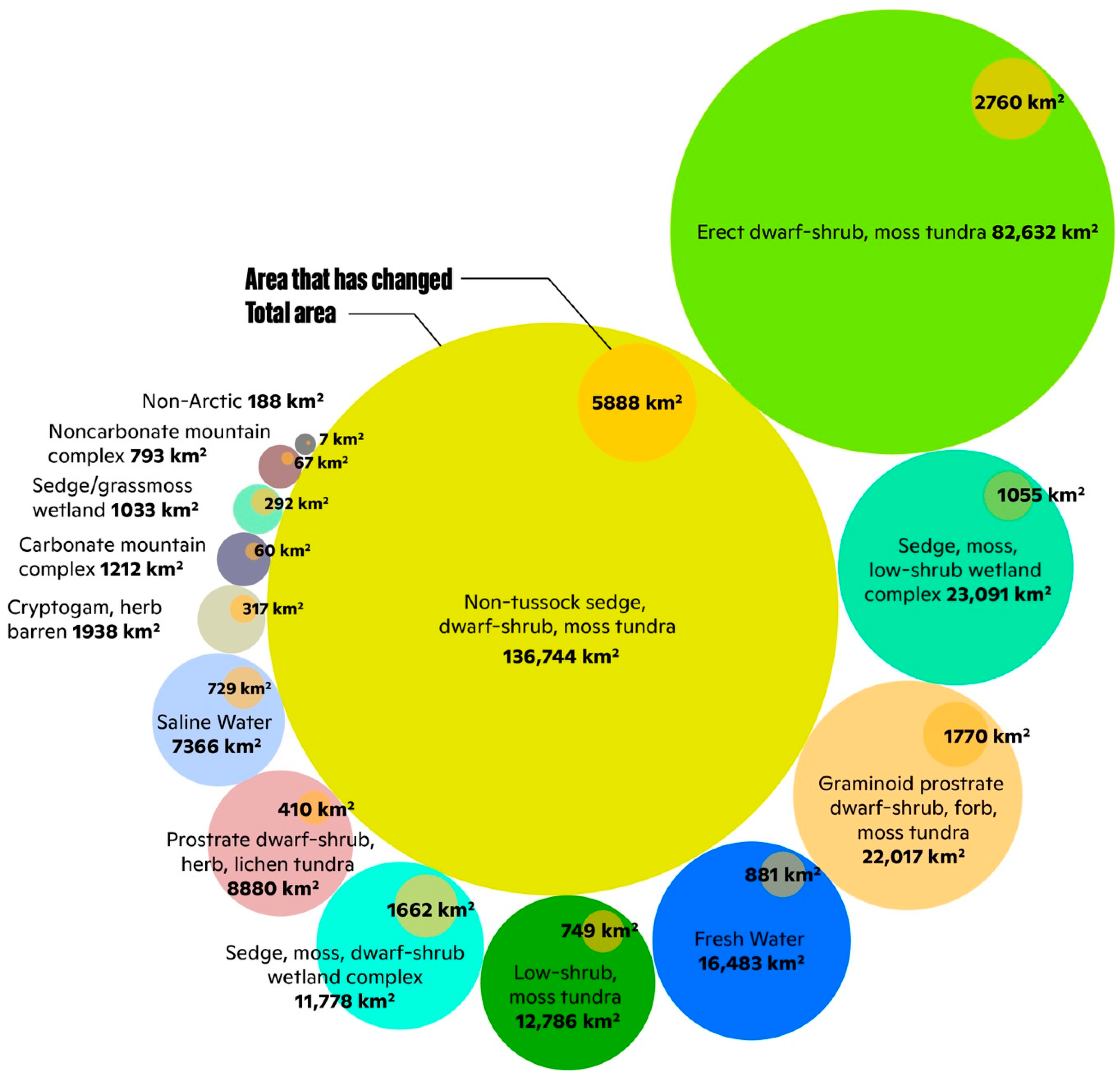
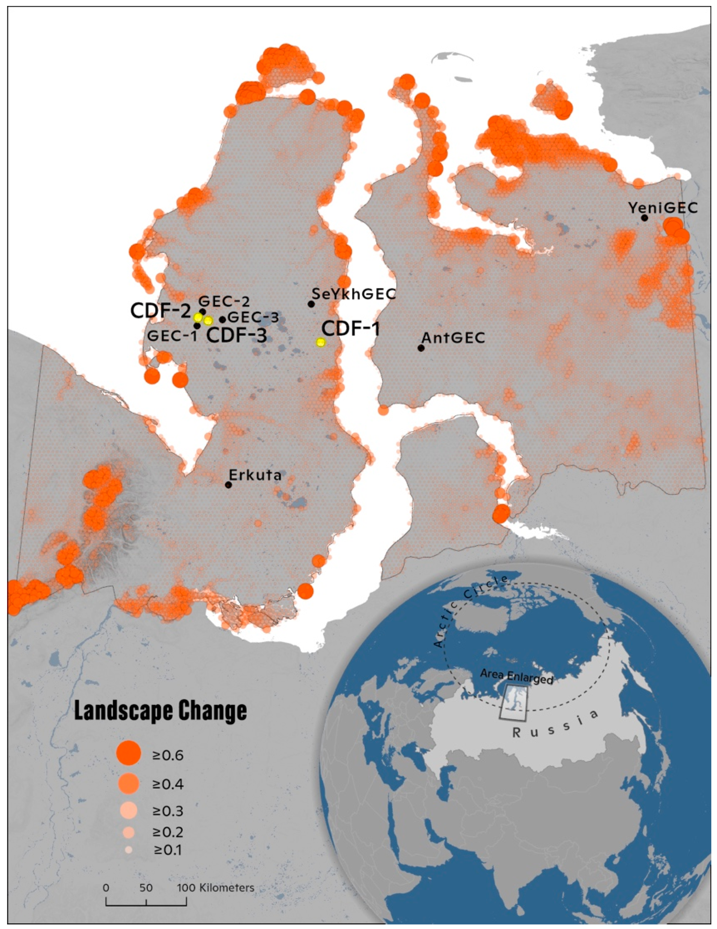
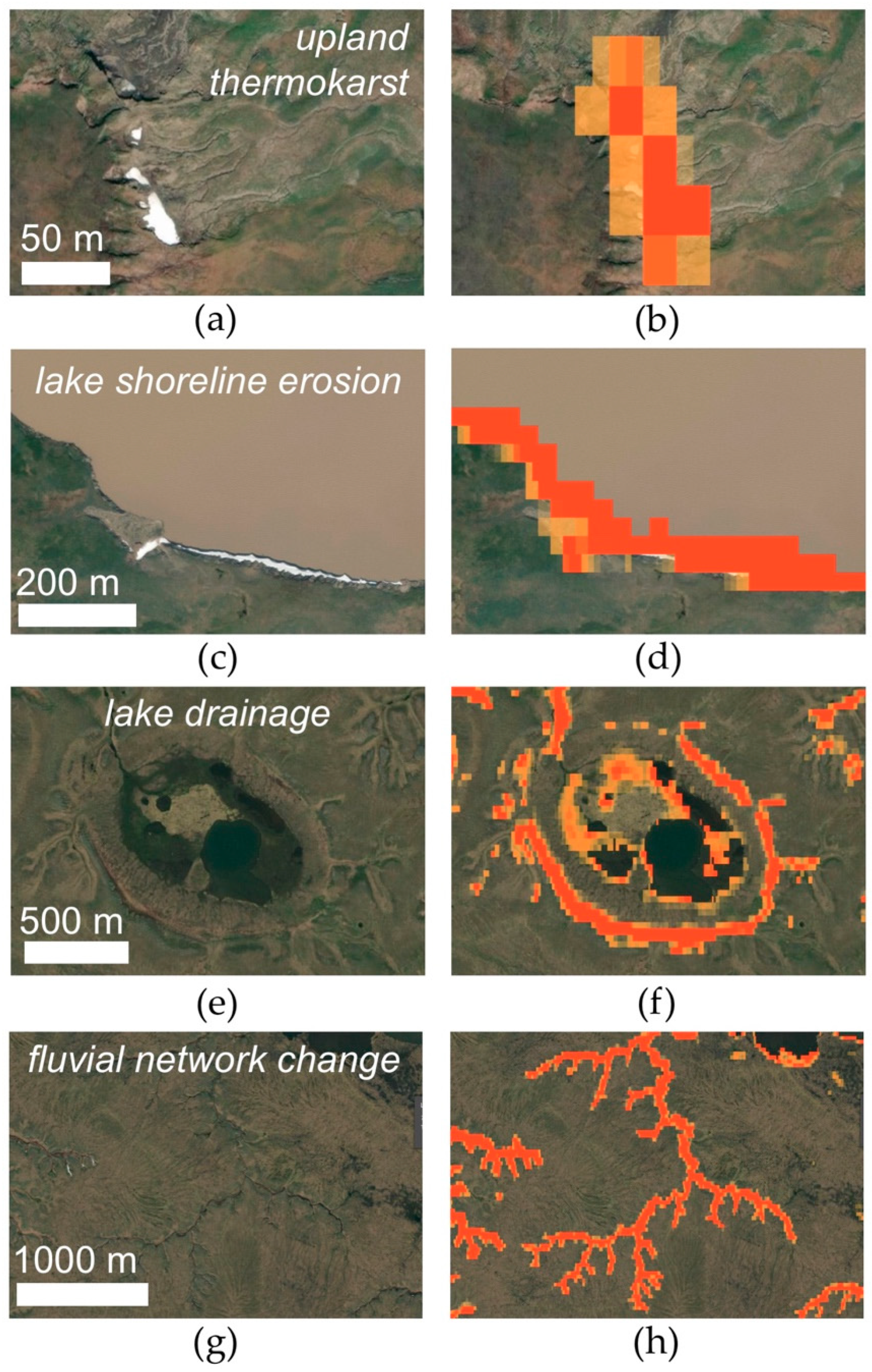
Across the 327,000 km2 study area, land cover was primarily classified as upland/non-wetland tundra (81%), with lower amounts of wetlands (11%), water (7%), and mountains/barren terrain (1%) (Table 1, Figure A2). Approximately 5% (16,600 km2) of the land surface showed changes in vegetation, elevation, and/or water extent (Figure 1 and Figure 2). Land surface change was generally greater along the shorelines of water bodies, along coasts and in northern regions, and in the Ural Mountains in the southwest of the study area (Figure 2). Land surface change occurred among 14 categories of vegetation of the CAVM, which could be generalized into four land cover categories (Table 1). The total area of change was greatest in upland/non-wetland tundra (11,600 km2), but this category showed the lowest amount of change relative to total area (4%). Compared to upland/non-wetland tundra, proportional change was roughly two times higher in wetland complexes, areas of surface water, and mountains/barren terrain (Table 1). We recognize that masking some mountainous terrain (Section 2.2.2) likely resulted in a conservative estimate of proportional change. Change was often relatively more intense (higher change pixel values) for upland thermokarst (Figure 3a,b), thermo-erosional features along lake shorelines (Figure 3c,d), exposed littoral zones (Figure 3e,f), and, in some regions, for headwater stream networks (Figure 3g,h).
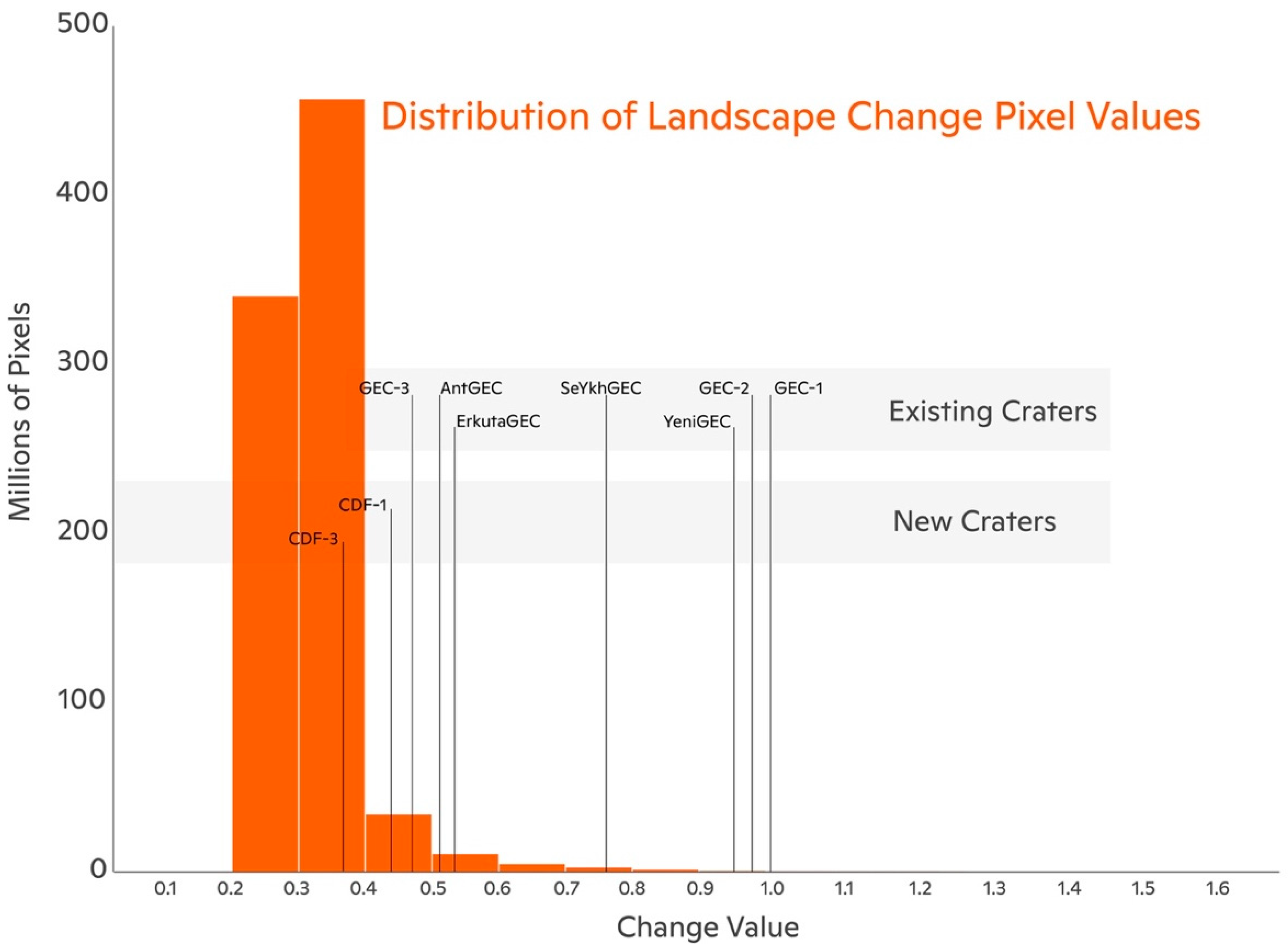
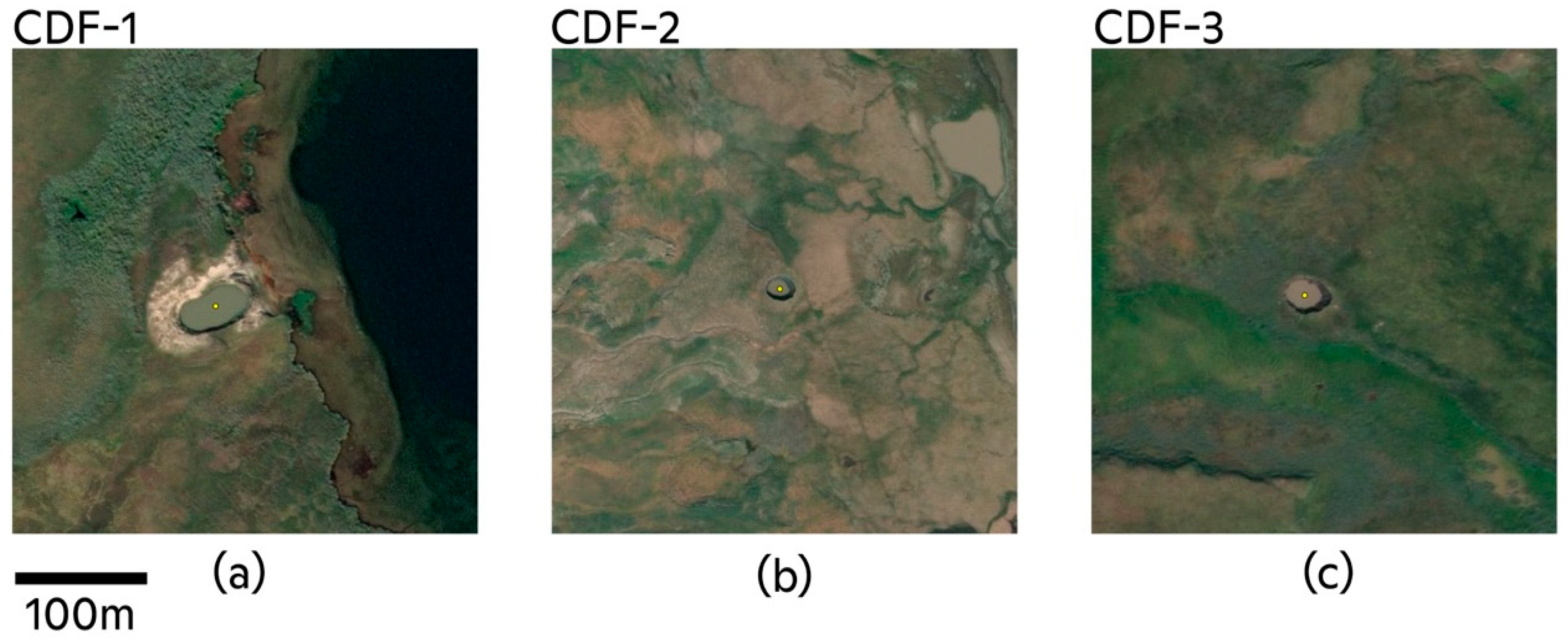
Pixel change values ranged from 0.10 to 1.62 and were generally low (median = 0.31, IQR = 0.29–0.33) relative to the maximum potential change (3.0). The distribution of values was right-skewed, indicating a smaller proportion of high-magnitude change values (Figure 4). Generally, previously identified GECs were associated with moderate values of land surface change (median = 0.78, n = 7). Values of land surface change associated with GECs were significantly greater than non-GEC change (p < 0.01, one-sample Wilcoxon Signed Rank Test). All GECs were located within upland/non-wetland tundra except for SeYkhGEC, which was located within a river in a wetland complex. Three additional GEC-like change detection features (CDF-1, CDF-2, CDF-3), which have not been previously reported, were detected during validation of the CDA (Figure 5). These three features were located in the central Yamal Peninsula, two of which were located approximately 40 km south of the Bovanenkovo gas field, in relatively close proximity to GEC-1, GEC-2, and GEC-3. Across the study area, RTSs were also prevalent. Within the 28,300 km2 of validated terrain, we found 150 terrain disturbance features that were likely to be RTSs. RTSs were present within 500 m of GEC-1, GEC-2, CDF-2 and not as close to the other GECs. AntGEc, SeYkhGEC, YeniGEC, and ErkutaGEC were located within ~400 m of terrain that appeared to be polygonal tundra.

3.2. Validation of Land Surface Change

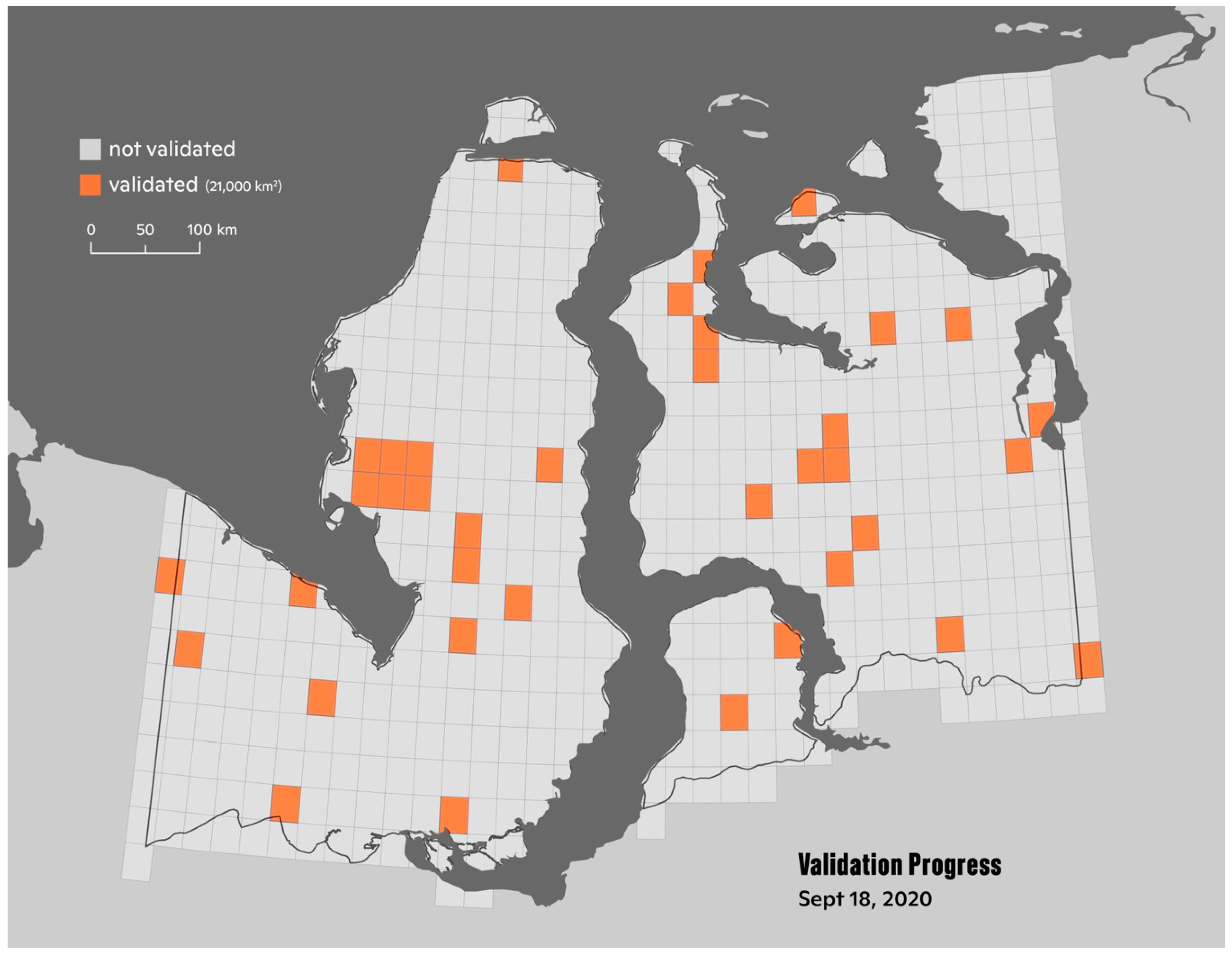
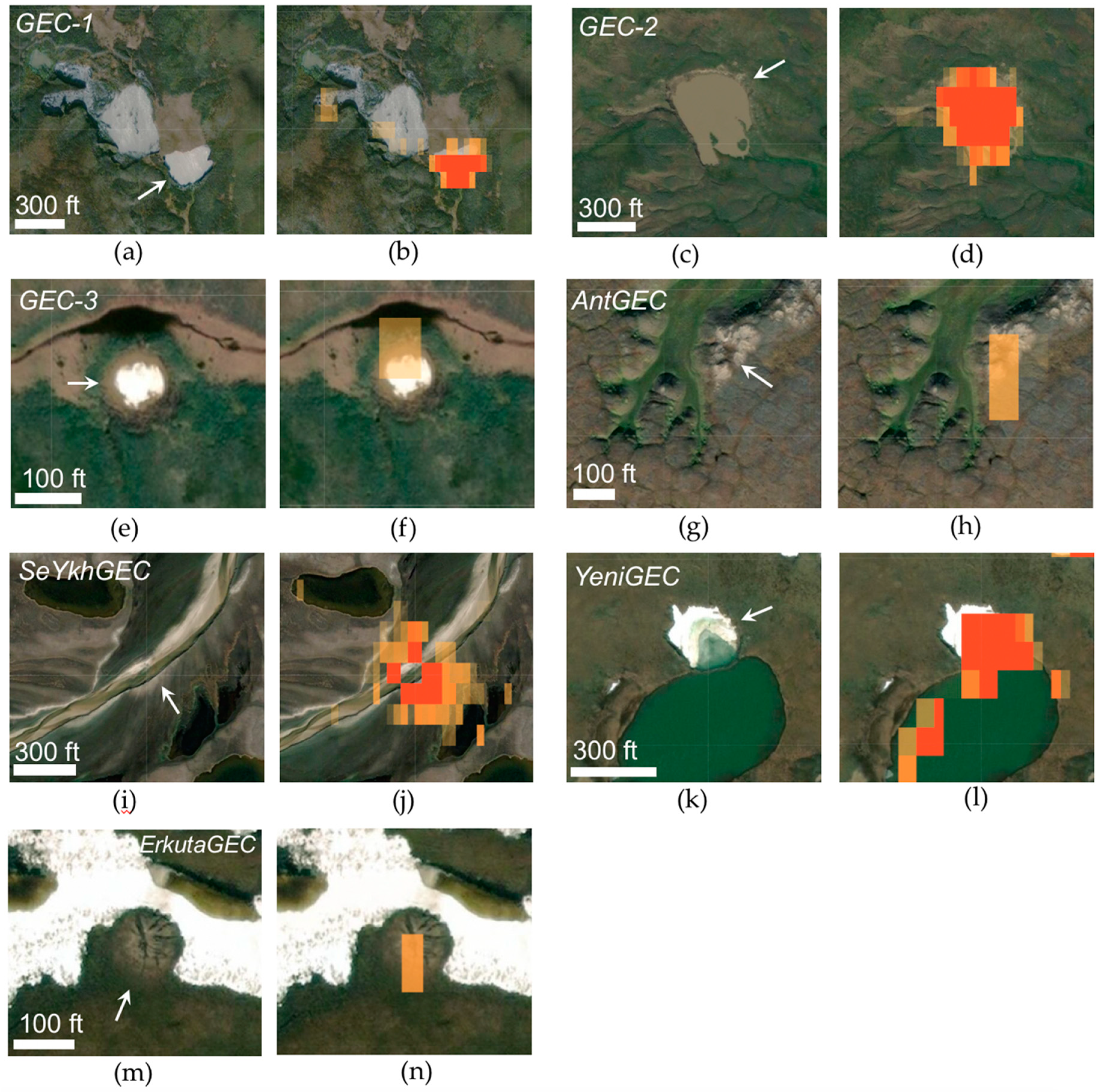
We validated 37 fishnet cells (6.1% of total), accounting for 28,300 km2 within the study area (Figure A3). The randomly selected fishnet cells represented 14 of the CAVM land cover categories (Table A2). Validation efforts revealed that all seven of the GECs previously reported in the literature (Table 2) were detected using the CDA (Figure A4). In addition to detecting land surface change associated with GEC formation, validation efforts further revealed that the CDA detected change that appeared to be due to declines in NDVI, loss or gain of surface water extent, and non-GEC geomorphic processes (e.g., lake shoreline erosion, RTS activity). Additionally, validation efforts identified 23 lakes having a visual appearance (e.g., morphometry, turbidity) similar to that of previously identified GECs. While 19 of these lakes were associated with change pixels, inspection of high-resolution satellite imagery archives found that none of the lakes were likely to be GECs.

3.3. Characteristics of GEC Formation from the Change Detection Algorithm and High-Resolution Satellite Imagery

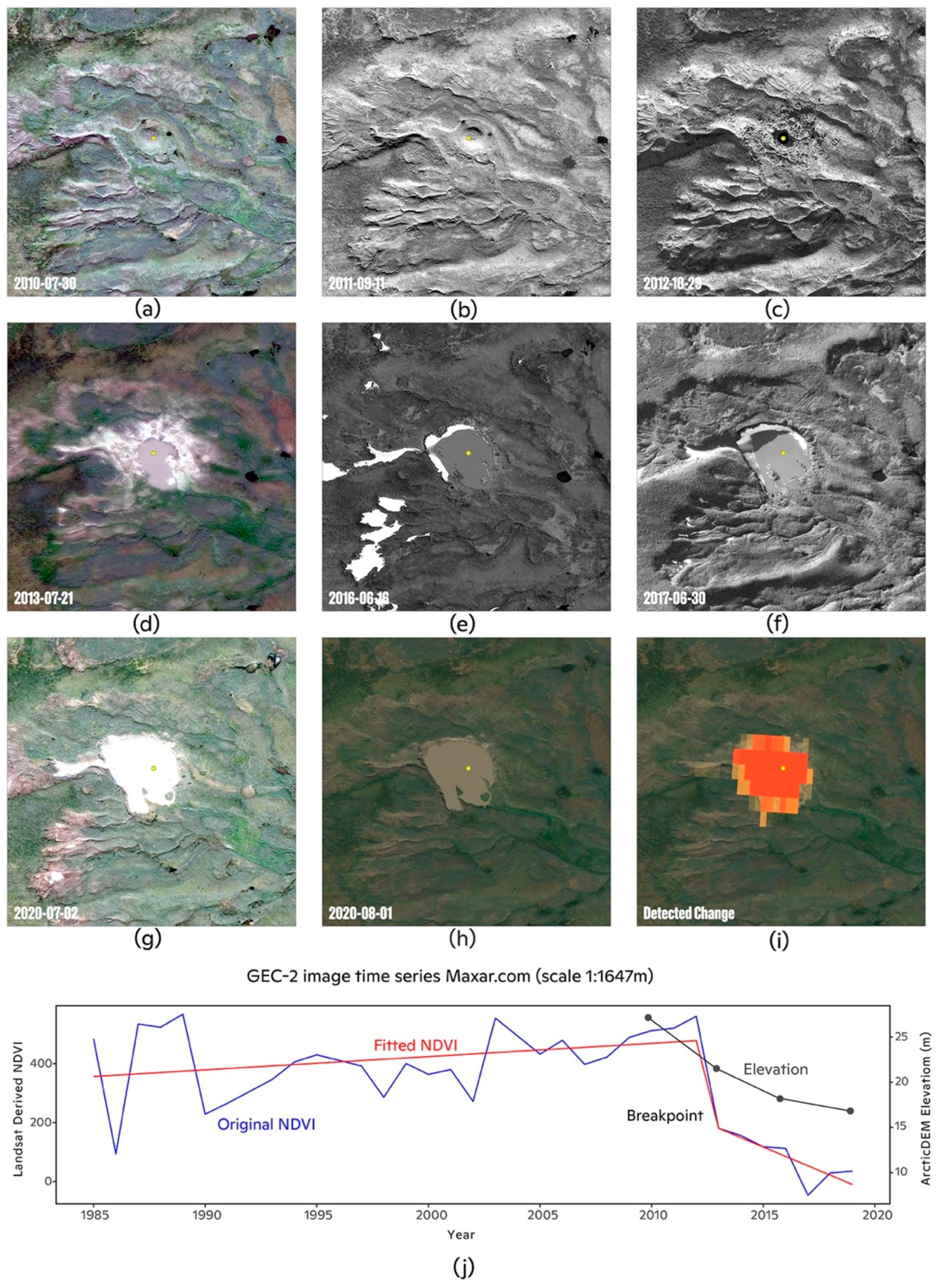
High-resolution satellite imagery together with elevation data from the ArcticDEM strips showed the geomorphic development of GEC-2 prior to (Figure 6a–h) and after its detection by the CDA (Figure 6i,j). CDA detection of GEC-2 was approximately coincident with its formation in late 2012. The CDA demarcated a cluster of pixels with a high magnitude of change centered on GEC-2 and the peripheral ejecta. Subsequent degradation of the crater parapet and apparent infilling of the GEC lake by precipitation, surface water, ground ice, and soil sediments resulted in the formation of a turbid, sub-circular lake ~0.1 km2 in area by August 2020. At least one dozen small ponds (2–10 m diameter) around the GEC lake periphery were visible in satellite imagery from August 2020. NDVI generally increased from 1985 until 2012. An abrupt decrease in NDVI showed as a distinct breakpoint in the time-series, signaling the formation of GEC-2 (Figure 6b). After the formation of GEC-2, NDVI values decreased until ~2019. Similarly, elevation values from the ArcticDEM decrease by ~5 m after GEC-2 formed, and decrease thereafter until 2018.
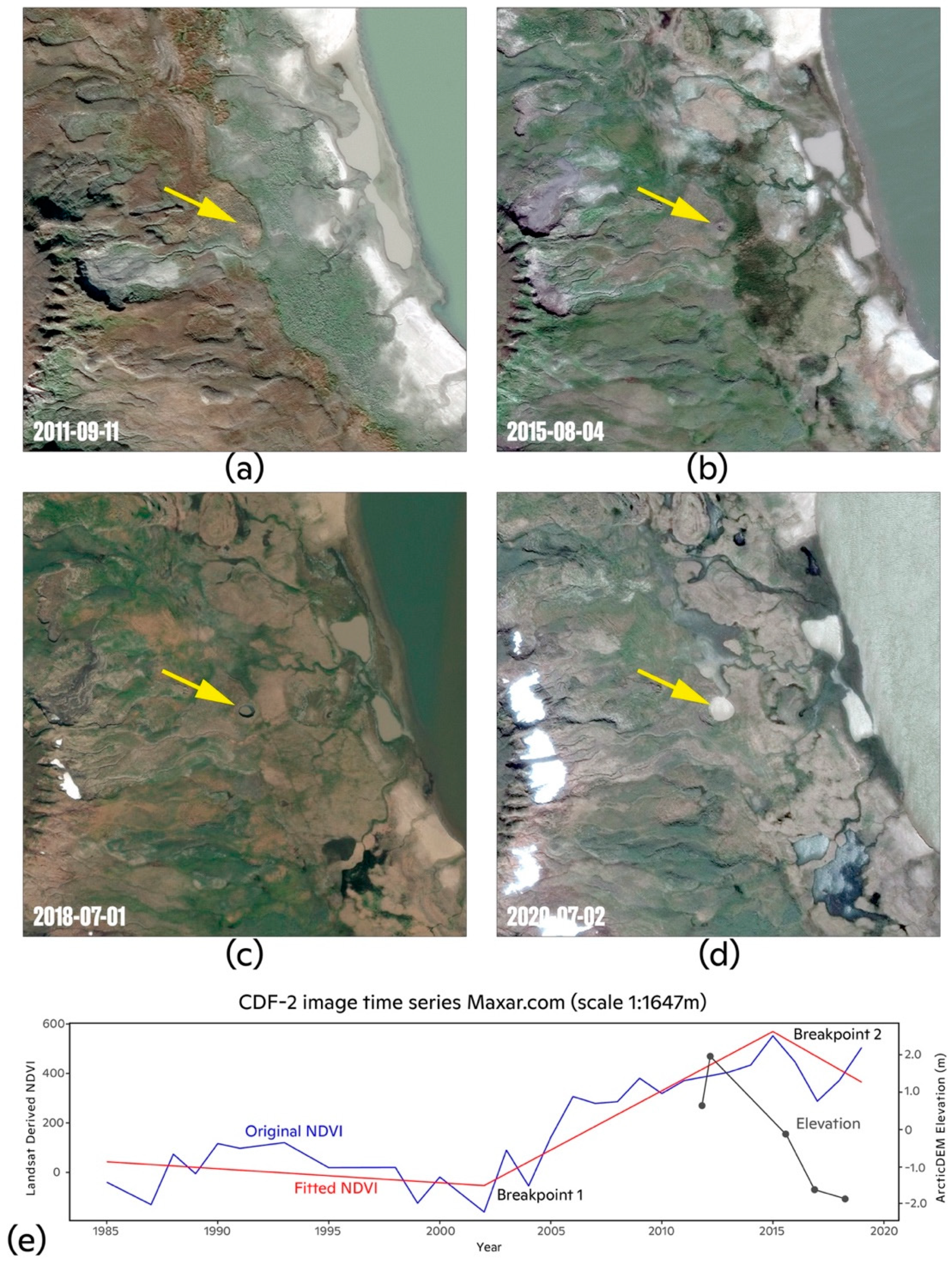
The landscape change features CDF-1, CDF-2, and CDF-3 have not been previously reported in the literature. CDF-1 was located 53 km south of SeYkhGEC. Satellite imagery of CDF-1 showed an elongate lake adorned by what appeared to be a sandy parapet encircling a lake with relatively low turbidity. There was no high-resolution, multi-year satellite imagery of CDF-1 with which to characterize its geomorphic evolution. CDF-2 was located 10.8 km due north of GEC-1 and was situated within the edge of a partially drained lake basin (Lake Khalevto), within 300 m of RTSs and polygonal tundra. Satellite imagery of CDF-2 showed a pingo-like feature in 2011, which had begun to degrade by August 2015 (Figure 7a,b). ArcticDEM elevation data indicate that the collapse of the feature apex occurred from ca. 2015 to 2017, resulting in a GEC-like crater by July 2018 with a diameter of 12–15 m (Figure 7c,d; Table 2). There was no evidence from the high-resolution satellite imagery of ejected debris around the periphery of the feature, nor signs of newly formed ponds associated with the thawing of ice-rich ejecta. Degradation of the feature parapet and infilling of the crater formed a ~600 m2 circular lake by July 2020 and the development of secondary thermokarst adjacent to the lake. Unlike GEC-2, NDVI was relatively constant from 1984 to 2002, increased from 2002 to 2015, and then decreased in conjunction with the collapse of the feature and formation of a lake (Figure 7e).
The development and morphometry of the feature CDF-3 appeared to be similar to that of CDF-2. CDF-3 was located 14.3 km northeast of GEC-1, within shrub-tundra. Satellite imagery showed the feature resembled a pingo in July 2010 and had degraded into a crater ~20–22 m in diameter by July 2013. Similar to CDF-2, there was no evidence for the explosive ejection of ground material associated with the formation of CDF-3. Imagery from May 2020 showed no evidence of degradation of the feature or growth of the lake within the crater.

4. Discussion

4.1. Multi-Decadal Land Surface Change on the Yamal and Gydan Peninsulas

The CDA revealed widespread land surface change across the Yamal-Gydan region in recent decades. Change was primarily associated with coastal regions—which is occurring at rates of 0.2–1.7 m y−1 in the Yamal-Gydan region [49]—surface water (e.g., lakes, streams, rivers), and geomorphically active terrain (e.g., thermokarst), which is not unexpected for lake-rich terrains hosting relatively ice-rich permafrost [5]. Change along lake shorelines is taken to reflect the expansion and/or drainage of thermokarst lakes, and change within fluvial networks may indicate changes in snow persistence or vegetation loss associated with thawing and subsiding riparian zones. These land surface changes occurred in tandem with an increase in mean summer (June–September) air temperature by 0.4 °C per decade from 1984 to 2017 (p < 0.05, Mann–Kendall test) in Salekhard, in the southern part of the study area, and warming of permafrost on the Yamal Peninsula (ca. +1 °C per decade, 2007–2016) [4]. Together, these findings indicate that geomorphic and hydrologic activity in the Yamal and Gydan peninsulas are driving widespread land surface change with largely unknown implications for regional ecosystems, biogeochemical cycles, and hazards to human populations and infrastructure.

4.2. Speculation on the Origins of the Three New GEC-Like Features

Of the three features, CDF-2 appeared most similar to a GEC upon first inspection of high-resolution satellite imagery acquired in July 2018 (Figure 7). Examination of historical high-resolution satellite imagery showed a mound predecessor in July 2011, within the margin of drained Lake Khalevto. Annual time-series of Landsat imagery in Google Earth Timelapse (https://earthengine.google.com/timelapse/) showed a minor decrease in water levels in Lake Khalevto in 2003, which was followed by a period of stability for five years and then lake drainage in the period 2008–2009. This aligns with NDVI trends, which started to increase around 2003 (Figure 7), perhaps reflecting the emergence and/or growth of vegetation following subaerial exposure of the littoral zone. Drained lake margins often contain the requisite geomorphic and hydrologic conditions for the formation of hydrostatic (i.e., closed system) pingos [50]. Within drained lakes, pingos typically form within residual ponds via the downward aggradation of permafrost, causing forceful expulsion of talik porewater, formation of intrusive ice, and upward heaving of the land surface [51,52]. In early stages, hydrostatic pingos are characterized by rapid early growth rates up to ~1.5 m y−1 [50] and, in following decades, on the order of cm y−1 [53]. Pingo degradation may occur over decades and show dilation (i.e., tension) cracks across the dome surface [50,54], though geomorphic characteristics of pingo collapse vary across the northern permafrost zone [51]. We presume that growth of the CDF-2 mound predecessor initiated between 2003 and 2008, when Lake Khalevto water levels began to decline. Assuming the height of CDF-2 reached ~3 to 4 m before collapse initiated (Figure 7), growth aligned with theoretical rates typical of early pingo formation. Thus, development of the CDF-2 mound predecessor was characteristic of both pingos and GECs. Curiously, Google Earth Timelapse reveals that CDF-2 did not originate within a residual pond. Therefore, CDF-2 may have originated as a hydraulic (open-system) pingo, provided a sufficient water source [50]. Relatively abrupt collapse of the CDF-2 dome is indicated by high-resolution satellite imagery collected in August 2015, and July 2018, resulting in the formation of a central pond and funnel-like upper crater walls (Figure 7). We presume that the abrupt loss of soil mechanical strength and subsequent dome collapse was coupled to the loss of internal pressure within CDF-2 via non-eruptive degassing of methane or loss of subsurface water. Subsequent thermokarst and exposure of permafrost would accelerate thaw, resulting in the turbid lake. From the available data, we can neither confirm that CDF-2 was a pingo, nor reject the hypothesis that it was a GEC that did not erupt explosively.
Google Earth Timelapse revealed that, unlike CDF-2, CDF-1 and CDF-3 were not located within drained lake or pond basins. While limited elevation data and historical high-resolution satellite imagery exist for CDF-1, its elongate nature, relatively low turbidity, and sand-adorned parapet were not characteristic of GECs [16,24,36,55]. We surmise it was a degraded pingo, or perhaps resulted via thermokarst lake formation. In contrast, high-resolution satellite imagery of CDF-3 showed geomorphic evolution more similar to that of CDF-2. Without additional information, we reason that CDF-3 could have formed from a collapsing pingo induced by the escape of subterranean water or thaw of ice-rich permafrost [56], or as a GEC that released its methane non-explosively. Why CDF-3 did not appear to show much, if any, degradation between 2013 and 2020 remains unknown. Relatively low change pixel values for CDF-3 and absence of breakpoints in its NDVI time-series are likely because the feature was smaller than the resolution of a Landsat pixel (30 m). These results highlight the limits of using remote-sensing to ascribe forms of geomorphic change in permafrost-affected terrains. The CDA detected previously undocumented GEC-like features and results suggest that not all GECs may erupt explosively. Validating land surface change features in the field is a top priority to advance understanding of these phenomena.

4.3. Performance of the Change Detection Algorithm

The CDA detected all seven of the GECs previously reported in the literature [16,24,36,55] and three new GEC-like features. Therefore, despite uncertainty whether the latter were GECs, these results demonstrate that our semi-automated CDA successfully detected land surface change associated with GECs. Importantly, however, GECs had already formed prior to detection by the CDA [16]. Detection of GECs after their formation is largely due to the CDA inputs (Figure 1), which weight breakpoints associated with abrupt changes in NDVI [41]. Such changes are most likely to occur after GECs form. This was reflected by relatively large clusters of high-value change pixels centered on lakes that formed within year(s) following GEC formation, such as for GEC-1, GEC-2 (Figure 6), and YeniGEC. Further, the CDA product simply represents net land surface change during the 1984–2017 period. The CDA does not as readily capture more subtle multi-year terrain uplift associated with mound predecessor formation [16]. For these reasons, and the laborious validation required for the CDA (Figure 1), our semi-automated approach represents a first step towards the automated detection of GECs. Further refinement of the algorithm is required to better isolate change associated with GECs from other types of land surface change, which would reduce validation time. On the other hand, although the CDA input parameters (Figure 1) were tuned for the detection of GECs, our results demonstrate that the CDA was sensitive to diverse types of land surface change that occur in the Yamal-Gydan region [19,22] and also in permafrost regions elsewhere. Thus, our CDA workflow (Figure 1) could be further refined to detect and monitor RTSs [57], lake or coastal shoreline erosion [58], and/or lake drainage across the circumpolar north [59].

4.4. Detection, Mapping, and Monitoring Northern Environmental Change

Geomorphic, hydrologic, and vegetation change across the northern permafrost zone encompasses a suite of land surface processes, including GECs, that can be expected to intensify with future warming [60,61,62]. Given the potential hazards to humans and infrastructure posed by GECs [17], detecting mound predecessors and predicting GEC formation in the Yamal-Gydan region is of top interest. Yet, the sparsity of known GECs hinders automated and remote detection of mound predecessors, and also the development of an approach to predict GEC formation [16]. Our results indicate that elevation change, a hallmark of mound predecessor formation, can be detected across broad scales using ICESat-corrected ArcticDEM data. Remote sensing campaigns which make repeat measurements of elevation at annual or sub-annual timescales could detect and monitor future regional land surface change associated with thermokarst activity [63]. For instance, the ESA Sentinel-1 and Sentinel-2 platforms (launched in 2014/2015) collect radar and multispectral imagery up to 84° N every 10 to 12 days at decameter spatial resolution (https://sentinel.esa.int). Sentinel-1 interferometric synthetic aperture radar (InSAR) data capture sub-decimeter vertical resolution of ground surface displacement [64] and could potentially enable detection and monitoring of GEC formation. Developing Sentinel data-based methods was beyond the scope of this work, which sought to identify trends in land surface change prior to the launch of the Sentinel platforms. Identifying changes in surface water extent using multispectral satellite imagery [12] could allow for detection and monitoring of areas considered conducive to GEC formation, such as drained thermokarst lake basins [55]. Other approaches for detecting GECs may be hindered by the limited number of documented GECs [16]. For instance, machine learning approaches show promise for mapping thermokarst based on the distinct spectral texture of thermokarst features [65], but require large amounts of input data for calibration and validation. In any case, feature detection is limited by the spatial resolution of imagery. Increasing accessibility to large amounts of remote sensing data and cloud-computing (e.g., Google Earth Engine) will push forward new avenues of research on land surface change at northern high latitudes [66]. Remote sensing methods for detecting and monitoring geomorphic, hydrologic, and vegetation change, which are rapidly evolving, are of utmost importance for understanding the extent, rate, and forms of permafrost thaw, and for mitigating effects to infrastructure [7] and ecosystems [6] across the circumpolar north.

5. Conclusions

In this study, we developed a semi-automated workflow using satellite remote sensing imagery to characterize land surface change and detect GECs on the Yamal and Gydan peninsulas. We found that 5% of the Yamal-Gydan region experienced changes in vegetation, elevation, and/or surface water from 1984 to 2017. Our change detection algorithm successfully identified the seven GECs previously reported in the scientific literature and three previously undocumented GEC-like features. Two of the newly identified features had geomorphic similarities to—and were located in an area nearby—several known GECs in the vicinity of the Bovanenkovo gas field. While less abundant than retrogressive thaw slumps in the Yamal-Gydan region, GEC activity is challenging to predict and poses a hazard to human populations and infrastructure. Our approach is a first step to detecting and monitoring the formation of GECs, which may be further improved and perhaps automated with additional observations of GECs. Refining methods to detect geomorphic activity will help to mitigate potential hazards and better understand regional variability in terrain responses to climate change across the northern permafrost zone.

Author Contributions

Conceptualization, S.M.N., G.F., S.Z., V.O., and A.F.; methodology, G.F., S.Z., and S.M.N.; software, G.F. and Z.Y.; validation, S.Z., G.F., T.W., G.D., and S.M.N.; formal analysis, G.F. and S.Z.; investigation, S.Z., G.F., T.W., Z.Y., V.O., A.F., and S.M.N.; resources, S.M.N. and Z.Y.; data curation, G.F. and S.Z.; writing—original draft preparation, S.Z., G.F., S.M.N., T.W., G.D., Z.Y., V.O., and A.F.; writing—review and editing, S.Z., G.F., S.M.N., T.W., G.D., Z.Y., V.O., and A.F.; visualization, G.F., S.Z.; supervision, S.M.N. and G.F.; project administration, S.M.N.; funding acquisition, S.M.N. and G.F. All authors have read and agreed to the published version of the manuscript.

Funding

This research was funded by the Heising Simons Foundation, grant number 2019–1501 and NASA, grant number NASA 18-RRNES18-0004.

Institutional Review Board Statement

Not applicable.

Informed Consent Statement

Not applicable.

Data Availability Statement

Data is contained within the article or supplementary material.

Acknowledgments

We thank Carl Churchill for assistance with delineating human disturbance; Kim Fiske for assistance with validating the GEC map; Paul Morin and Ian Howat (University of Minnesota Polar Geospatial Center) for insightful conversations about the ArcticDEM; and four anonymous reviewers for their constructive feedback, which greatly helped to improve the manuscript.

Conflicts of Interest

The authors declare no conflict of interest.

Appendix A

Example code for correcting ArcticDEM data to ICESat spaceborne lidar can be found here:

Appendix B

Table A1. Input parameters used in the LandTrendr analysis. Detailed descriptions of input parameters can be found in the LandTrendr for Google Earth Engine guide (https://emapr.github.io/LT-GEE/api.html) and in the literature [41].
Parameter TypeLandTrendr VarValue
Collection (Landsat)startYear1984
endYear2018
startDay05-01
endDay09-30
indexNDVI
maskThese[‘cloud’, ‘shadow’, ‘snow’]
Changedeltaloss
sortgreatest
year1984–2018
mag>200
dur<20
prevalN/A
mmuN/A
LandTrendrmaxSegments3
spikeThreshold0.9
vertexCountOvershoot3
preventOneYearRecoveryTrue
recoveryThreshold0.04
pvalThreshold0.05
bestModelProportion0.75
minObservationsNeeded6

Appendix C

Table A2. Total area and change among vegetation and land cover categories defined by the circumpolar arctic vegetation map (CAVM) [27].
CAVM CategoryTotal (km2)Total Area (%)Total Change (km2)Change Proportion
Sedge/grass moss wetland 110330.32920.28
Cryptogram, herb barren 219380.63170.16
Sedge, moss, dwarf-shrub wetland complex 111,7783.616620.14
Saline water 373662.37290.10
Non-carbonate mountain complex 27930.2670.08
Graminoid prostrate dwarf-shrub, forb, moss tundra 422,0176.717700.08
Low-shrub, moss tundra412,7863.97490.06
Freshwater 316,4835.08810.05
Carbonate mountain complex 212120.4600.05
Prostrate dwarf-shrub, herb, lichen tundra 488802.74100.05
Sedge, moss, low-shrub wetland complex 123,0917.110550.05
Non-tussock sedge, dwarf-shrub, moss tundra 4136,74441.858880.04
Non-Arctic1880.170.04
Erect dwarf-shrub, moss tundra 482,63225.327600.03
1 Wetland complex; 2 Mountains/barren terrain; 3 Water; 4 Upland/non-wetland tundra.

Appendix D

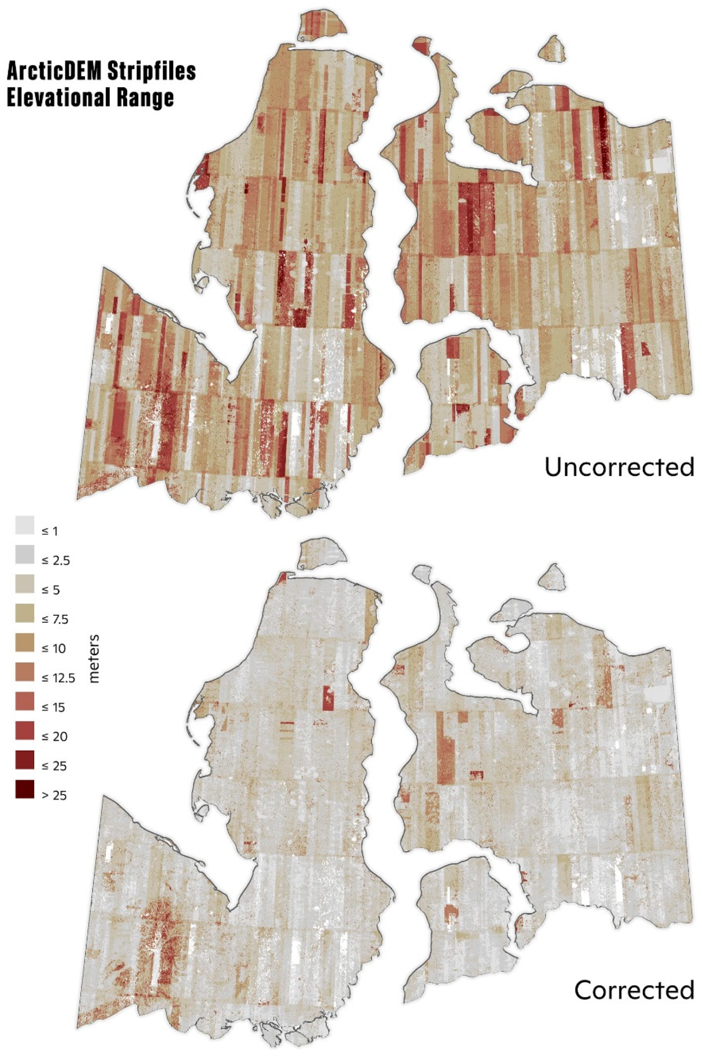
Figure A1. Change in elevation across the study area from 2008 to 2017, derived using the ArcticDEM digital surface model [13]. Vertical discrepancy among ArcticDEM strips (uncorrected, top panel) was corrected using the ICESat altimetry offset (corrected, bottom panel) (see Section 2.2).
Geosciences 11 00021 g0a1

Appendix E

Figure A2. Area of landscape change visualized as a proportion of total area, for categories of land surface types (n = 14) within the study area. Land surface categories were extracted from the circumpolar arctic vegetation map [27].
Geosciences 11 00021 g0a2

Appendix F

Figure A3. Distribution of fishnet cells across the study area (outlined in dark gray). Out of 604 fishnet cells within the study area, 37 (6.1%) were validated, accounting for 28,300 km2.
Geosciences 11 00021 g0a3
Figure A4. High-resolution satellite imagery of the seven gas emission craters (GECs) previously reported in the literature (Table 2), shown without change pixels (left panel) and with change pixels (right panel) for GEC-1 (a,b), GEC-2 (c,d), GEC-3 (e,f), AntGEC (g,h), SeYkhGEC (i,j), YeniGEC (k,l), and ErkutaGEC (m,n). Note: due to the difficulty of obtaining cloud-free, high-resolution imagery during the relatively brief period during which the characteristic crater stage of GEC evolution, most images show the GECs prior to (e.g., ErkutaGEC) or after (e.g., YeniGEC) their formation. Imagery © 2020, DigitalGlobe.
Geosciences 11 00021 g0a4

References

  1. Serreze, M.C.; Barry, R.G. Processes and impacts of Arctic amplification: A research synthesis. Glob. Planet. Change 2011, 77, 85–96. [Google Scholar] [CrossRef]
  2. Rawlins, M.A.; Steele, M.; Holland, M.M.; Adam, J.C.; Cherry, J.E.; Francis, J.A.; Groisman, P.Y.; Hinzman, L.D.; Huntington, T.G.; Kane, D.L.; et al. Analysis of the Arctic System for Freshwater Cycle Intensification: Observations and Expectations. J. Clim. 2010, 23, 5715–5737. [Google Scholar] [CrossRef]
  3. Bjorkman, A.D.; Myers-Smith, I.H.; Elmendorf, S.C.; Normand, S.; Rüger, N.; Beck, P.S.A.; Blach-Overgaard, A.; Blok, D.; Cornelissen, J.H.C.; Forbes, B.C.; et al. Plant functional trait change across a warming tundra biome. Nature 2018, 562, 57–62. [Google Scholar] [CrossRef] [PubMed]
  4. Biskaborn, B.K.; Smith, S.L.; Noetzli, J.; Matthes, H.; Vieira, G.; Streletskiy, D.A.; Schoeneich, P.; Romanovsky, V.E.; Lewkowicz, A.G.; Abramov, A.; et al. Permafrost is warming at a global scale. Nat. Commun. 2019, 10, 1–11. [Google Scholar] [CrossRef] [PubMed] [Green Version]
  5. Grosse, G.; Jones, B.; Arp, C. Thermokarst Lakes, Drainage, and Drained Basins. In Treatise on Geomorphology; Academic Press: San Diego, CA, USA, 2013; pp. 325–353. ISBN 978-0-08-088522-3. [Google Scholar]
  6. Schuur, E.A.G.; Mack, M.C. Ecological Response to Permafrost Thaw and Consequences for Local and Global Ecosystem Services. Annu. Rev. Ecol. Evol. Syst. 2018, 49, 279–301. [Google Scholar] [CrossRef]
  7. Hjort, J.; Karjalainen, O.; Aalto, J.; Westermann, S.; Romanovsky, V.E.; Nelson, F.E.; Etzelmüller, B.; Luoto, M. Degrading permafrost puts Arctic infrastructure at risk by mid-century. Nat. Commun. 2018, 9. [Google Scholar] [CrossRef]
  8. Van der Sluijs, J.; Kokelj, S.V.; Fraser, R.H.; Tunnicliffe, J.; Lacelle, D. Permafrost Terrain Dynamics and Infrastructure Impacts Revealed by UAV Photogrammetry and Thermal Imaging. Remote Sens. 2018, 10, 1734. [Google Scholar] [CrossRef] [Green Version]
  9. Rees, W.G.; Williams, M.; Vitebsky, P. Mapping land cover change in a reindeer herding area of the Russian Arctic using Landsat TM and ETM+ imagery and indigenous knowledge. Remote Sens. Environ. 2003, 85, 441–452. [Google Scholar] [CrossRef]
  10. Fraser, R.H.; Olthof, I.; Carrière, M.; Deschamps, A.; Pouliot, D. Detecting long-term changes to vegetation in northern Canada using the Landsat satellite image archive. Environ. Res. Lett. 2011, 6, 045502. [Google Scholar] [CrossRef] [Green Version]
  11. Ju, J.; Masek, J.G. The vegetation greenness trend in Canada and US Alaska from 1984–2012 Landsat data. Remote Sens. Environ. 2016, 176, 1–16. [Google Scholar] [CrossRef]
  12. Pekel, J.-F.; Cottam, A.; Gorelick, N.; Belward, A.S. High-resolution mapping of global surface water and its long-term changes. Nature 2016, 540, 418–422. [Google Scholar] [CrossRef] [PubMed]
  13. Morin, P.; Porter, C.; Cloutier, M.; Howat, I.; Noh, M.-J.; Willis, M.; Bates, B.; Willamson, C.; Peterman, K. ArcticDEM.; A Publically Available, High Resolution Elevation Model of the Arctic. In Proceedings of the Geophysical Research Abstracts, Vienna, Austria, 17–22 April 2016; Volume 18, p. 1. [Google Scholar]
  14. Dai, C.; Howat, I.M. Measuring Lava Flows with ArcticDEM: Application to the 2012–2013 Eruption of Tolbachik, Kamchatka. Geophys. Res. Lett. 2017, 44, 12,133–12,140. [Google Scholar] [CrossRef] [Green Version]
  15. Gorelick, N.; Hancher, M.; Dixon, M.; Ilyushchenko, S.; Thau, D.; Moore, R. Google Earth Engine: Planetary-scale geospatial analysis for everyone. Remote Sens. Environ. 2017, 202, 18–27. [Google Scholar] [CrossRef]
  16. Kizyakov, A.; Leibman, M.; Zimin, M.; Sonyushkin, A.; Dvornikov, Y.; Khomutov, A.; Dhont, D.; Cauquil, E.; Pushkarev, V.; Stanilovskaya, Y. Gas Emission Craters and Mound-Predecessors in the North of West Siberia, Similarities and Differences. Remote Sens. 2020, 12, 2182. [Google Scholar] [CrossRef]
  17. Dvornikov, Y.A.; Leibman, M.O.; Khomutov, A.V.; Kizyakov, A.I.; Semenov, P.; Bussmann, I.; Babkin, E.M.; Heim, B.; Portnov, A.; Babkina, E.A.; et al. Gas-emission craters of the Yamal and Gydan peninsulas: A proposed mechanism for lake genesis and development of permafrost landscapes. Permafr. Periglac. Process. 2019, 2014. [Google Scholar] [CrossRef] [Green Version]
  18. Bogoyavlensky, V.I.; Sizov, O.S.; Nikonov, R.A.; Bogoyavlensky, I.V.; Kargina, T.N. Earth degassing in the Arctic: The genesis of natural and anthropogenic methane emissions. Arct. Ecol. Econ. 2020, 6–22. [Google Scholar] [CrossRef]
  19. Leibman, M.; Kizyakov, A.; Plekhanov, A.; Streletskaya, I. Russia New Permafrost Feature–Deep Crater in Central Yamal (West Siberia, Russia) as a Response to Local Climate Fluctuations. Geogr. Environ. Sustain. 2014, 7, 68–80. [Google Scholar] [CrossRef]
  20. Kizyakov, A.; Khomutov, A.; Zimin, M.; Khairullin, R.; Babkina, E.; Dvornikov, Y.; Leibman, M. Microrelief Associated with Gas Emission Craters: Remote-Sensing and Field-Based Study. Remote Sens. 2018, 10, 677. [Google Scholar] [CrossRef] [Green Version]
  21. Chuvilin, E.; Ekimova, V.; Davletshina, D.; Sokolova, N.; Bukhanov, B. Evidence of Gas Emissions from Permafrost in the Russian Arctic. Geosciences 2020, 10, 383. [Google Scholar] [CrossRef]
  22. Leibman, M.O. Cryogenic landslides on the Yamal Peninsula, Russia: Preliminary observations. Permafr. Periglac. Process. 1995, 6, 259–264. [Google Scholar] [CrossRef]
  23. Segal, R.A.; Lantz, T.C.; Kokelj, S.V. Acceleration of thaw slump activity in glaciated landscapes of the Western Canadian Arctic. Environ. Res. Lett. 2016, 11, 034025. [Google Scholar] [CrossRef]
  24. Bogoyavlensky, V.; Bogoyavlensky, I.; Nikonov, R.; Kishankov, A. Complex of Geophysical Studies of the Seyakha Catastrophic Gas Blowout Crater on the Yamal Peninsula, Russian Arctic. Geosciences 2020, 10, 215. [Google Scholar] [CrossRef]
  25. Bogoyavlensky, V.I.; Sizov, O.S.; Bogoyavlensky, I.V.; Nikonov, R.A. Remote Site Detection surface gas and gas Arctic Emissions: Yamal Peninsula. Arktika 2016, 3, 4–15. [Google Scholar]
  26. CAVM Team Circumpolar Arctic Vegetation Map. 2003. Available online: https://www.geobotany.uaf.edu/cavm/ (accessed on 30 December 2020).
  27. Raynolds, M.K.; Walker, D.A.; Balser, A.; Bay, C.; Campbell, M.; Cherosov, M.M.; Daniëls, F.J.A.; Eidesen, P.B.; Ermokhina, K.A.; Frost, G.V.; et al. A raster version of the Circumpolar Arctic Vegetation Map (CAVM). Remote Sens. Environ. 2019, 232, 111297. [Google Scholar] [CrossRef]
  28. Brown, J.; Ferrians, O.J., Jr.; Heginbottom, J.A.; Melnikov, E.S. Circum-Arctic Map of Permafrost and Ground-Ice Conditions; USGS: Reston, VA, USA, 1997. [Google Scholar]
  29. Kizyakov, A.; Zimin, M.; Sonyushkin, A.; Dvornikov, Y.; Khomutov, A.; Leibman, M. Comparison of Gas Emission Crater Geomorphodynamics on Yamal and Gydan Peninsulas (Russia), Based on Repeat Very-High-Resolution Stereopairs. Remote Sens. 2017, 9, 1023. [Google Scholar] [CrossRef] [Green Version]
  30. Biskaborn, B.K.; Lanckman, J.-P.; Lantuit, H.; Elger, K.; Streletskiy, D.A.; Cable, W.L.; Romanovsky, V.E. The new database of the Global Terrestrial Network for Permafrost (GTN-P). Earth Syst. Sci. Data 2015, 7, 245–259. [Google Scholar] [CrossRef] [Green Version]
  31. Streletskaya, I.D.; Leibman, M.O. Cryogeochemical Model of Tabular Ground Ice and Cryopegs, Yamal Peninsula, Russia; Swets & Zeitlinger: Lisse, The Netherlands, 2003; pp. 1111–1115. [Google Scholar]
  32. Buldovicz, S.N.; Khilimonyuk, V.Z.; Bychkov, A.Y.; Ospennikov, E.N.; Vorobyev, S.A.; Gunar, A.Y.; Gorshkov, E.I.; Chuvilin, E.M.; Cherbunina, M.Y.; Kotov, P.I.; et al. Cryovolcanism on the Earth: Origin of a Spectacular Crater in the Yamal Peninsula (Russia). Sci. Rep. 2018, 8, 13534. [Google Scholar] [CrossRef]
  33. Kizyakov, A.I.; Sonyushkin, A.V.; Leibman, M.O.; Zimin, M.V.; Khomutov, A.V. Geomorphological conditions of the gas-emission crater and its dynamics in Central Yamal. Earth’s Cryosphere 2015, 14, 13–22. [Google Scholar]
  34. Savvichev, A.; Leibman, M.; Kadnikov, V.; Kallistova, A.; Pimenov, N.; Ravin, N.; Dvornikov, Y.; Khomutov, A. Microbiological Study of Yamal Lakes: A Key to Understanding the Evolution of Gas Emission Craters. Geosciences 2018, 8, 478. [Google Scholar] [CrossRef] [Green Version]
  35. Vorobyev, S.; Bychkov, A.; Khilimonyuk, V.; Buldovicz, S.; Ospennikov, E.; Chuvilin, E. Formation of the Yamal Crater in Northern West Siberia: Evidence from Geochemistry. Geosciences 2019, 9, 515. [Google Scholar] [CrossRef] [Green Version]
  36. Chuvilin, E.; Sokolova, N.; Davletshina, D.; Bukhanov, B.; Stanilovskaya, J.; Badetz, C.; Spasennykh, M. Conceptual Models of Gas Accumulation in the Shallow Permafrost of Northern West Siberia and Conditions for Explosive Gas Emissions. Geosciences 2020, 10, 195. [Google Scholar] [CrossRef]
  37. Ulmishek, G.F. Petroleum Geology and Resources of the West Siberian Basin, Russia; U.S. Geological Survey: Reston, Virginia, USA, 2003. [Google Scholar]
  38. Forbes, B.C.; Stammler, F.; Kumpula, T.; Meschtyb, N.; Pajunen, A.; Kaarlejärvi, E. High resilience in the Yamal-Nenets social–ecological system, west Siberian Arctic, Russia. Proc. Natl. Acad. Sci. USA 2009, 106, 22041–22048. [Google Scholar] [CrossRef] [Green Version]
  39. Kumpula, T.; Forbes, B.C.; Stammler, F. Remote Sensing and Local Knowledge of Hydrocarbon Exploitation: The Case of Bovanenkovo, Yamal Peninsula, West Siberia, Russia. Arctic 2010, 63, 165–178. [Google Scholar] [CrossRef]
  40. World Meteorological Organization Climate Explorer. Available online: https://climexp.knmi.nl/start.cgi (accessed on 25 October 2020).
  41. Kennedy, R.E.; Yang, Z.; Cohen, W.B. Detecting trends in forest disturbance and recovery using yearly Landsat time series: 1. LandTrendr—Temporal segmentation algorithms. Remote Sens. Environ. 2010, 114, 2897–2910. [Google Scholar] [CrossRef]
  42. Guay, K.C.; Beck, P.S.A.; Berner, L.T.; Goetz, S.J.; Baccini, A.; Buermann, W. Vegetation productivity patterns at high northern latitudes: A multi-sensor satellite data assessment. Glob. Change Biol. 2014, 20, 3147–3158. [Google Scholar] [CrossRef] [PubMed]
  43. Kennedy, R.; Yang, Z.; Gorelick, N.; Braaten, J.; Cavalcante, L.; Cohen, W.; Healey, S. Implementation of the LandTrendr Algorithm on Google Earth Engine. Remote Sens. 2018, 10, 691. [Google Scholar] [CrossRef] [Green Version]
  44. Foga, S.; Scaramuzza, P.L.; Guo, S.; Zhu, Z.; Dilley, R.D.; Beckmann, T.; Schmidt, G.L.; Dwyer, J.L.; Joseph Hughes, M.; Laue, B. Cloud detection algorithm comparison and validation for operational Landsat data products. Remote Sens. Environ. 2017, 194, 379–390. [Google Scholar] [CrossRef] [Green Version]
  45. Landis, J.R.; Koch, G.G. The Measurement of Observer Agreement for Categorical Data. Biometrics 1977, 33, 159. [Google Scholar] [CrossRef] [Green Version]
  46. R Core Team. R Core Team 2019; R Foundation for Statistical Computing: Vienna, Austria, 2019. [Google Scholar]
  47. Bronaugh, D.; Werner, A. zyp: Zhang + Yue-Pilon Trends Package; Pacific Climate Impacts Consortium: Victoria, BC, Canada, 2013. [Google Scholar]
  48. Yue, S.; Pilon, P.; Phinney, B.; Cavadias, G. The influence of autocorrelation on the ability to detect trend in hydrological series. Hydrol. Process. 2002, 16, 1807–1829. [Google Scholar] [CrossRef]
  49. Lantuit, H.; Overduin, P.P.; Couture, N.; Wetterich, S.; Aré, F.; Atkinson, D.; Brown, J.; Cherkashov, G.; Drozdov, D.; Forbes, D.L.; et al. The Arctic Coastal Dynamics Database: A New Classification Scheme and Statistics on Arctic Permafrost Coastlines. Estuaries Coast. 2012, 35, 383–400. [Google Scholar] [CrossRef] [Green Version]
  50. French, H.M. The Periglacial Environment, 4th ed.; Wiley-Blackwell: Hoboken, NJ, USA, 2018; ISBN 978-1-119-13281-3. [Google Scholar]
  51. Mackay, J.R. The Growth of Pingos, Western Arctic Coast, Canada. Can. J. Earth Sci. 1973, 10, 979–1004. [Google Scholar] [CrossRef]
  52. Samsonov, S.V.; Lantz, T.C.; Kokelj, S.V.; Zhang, Y. Growth of a young pingo in the Canadian Arctic observed by RADARSAT-2 interferometric satellite radar. Cryosphere 2016, 10, 799–810. [Google Scholar] [CrossRef] [Green Version]
  53. Mackay, J.R. Aklisuktuk (Growing Fast) Pingo, Tuktoyaktuk Peninsula, Northwest Territories, Canada. Arctic 1981, 34, 270–273. [Google Scholar] [CrossRef] [Green Version]
  54. Mackay, J.R. Pingo collapse and paleoclimatic reconstruction. Can. J. Earth Sci. 1988, 25, 495–511. [Google Scholar] [CrossRef]
  55. Chuvilin, E.; Stanilovskaya, J.; Titovsky, A.; Sinitsky, A.; Sokolova, N.; Bukhanov, B.; Spasennykh, M.; Cheremisin, A.; Grebenkin, S.; Davletshina, D.; et al. A Gas-Emission Crater in the Erkuta River Valley, Yamal Peninsula: Characteristics and Potential Formation Model. Geosciences 2020, 10, 170. [Google Scholar] [CrossRef]
  56. Mackay, J.R. Pingos of the Tuktoyaktuk Peninsula Area, Northwest Territories. Géographie Phys. Quat. 1979, 33, 3–61. [Google Scholar] [CrossRef] [Green Version]
  57. Brooker, A.; Fraser, R.H.; Olthof, I.; Kokelj, S.V.; Lacelle, D. Mapping the Activity and Evolution of Retrogressive Thaw Slumps by Tasselled Cap Trend Analysis of a Landsat Satellite Image Stack. Permafr. Periglac. Process. 2014, 25, 243–256. [Google Scholar] [CrossRef]
  58. Fritz, M.; Vonk, J.E.; Lantuit, H. Collapsing Arctic coastlines. Nat. Clim. Change 2017, 7, 6–7. [Google Scholar] [CrossRef] [Green Version]
  59. Jones, B.M.; Grosse, G.; Arp, C.D.; Jones, M.C.; Walter Anthony, K.M.; Romanovsky, V.E. Modern thermokarst lake dynamics in the continuous permafrost zone, northern Seward Peninsula, Alaska. J. Geophys. Res. 2011, 116, G00M03. [Google Scholar] [CrossRef]
  60. Kokelj, S.V.; Lantz, T.C.; Tunnicliffe, J.; Segal, R.; Lacelle, D. Climate-driven thaw of permafrost preserved glacial landscapes, northwestern Canada. Geology 2017, 45, 371–374. [Google Scholar] [CrossRef] [Green Version]
  61. Liljedahl, A.K.; Boike, J.; Daanen, R.P.; Fedorov, A.N.; Frost, G.V.; Grosse, G.; Hinzman, L.D.; Iijma, Y.; Jorgenson, J.C.; Matveyeva, N.; et al. Pan-Arctic ice-wedge degradation in warming permafrost and its influence on tundra hydrology. Nat. Geosci. 2016, 9, 312–318. [Google Scholar] [CrossRef]
  62. Myers-Smith, I.H.; Kerby, J.T.; Phoenix, G.K.; Bjerke, J.W.; Epstein, H.E.; Assmann, J.J.; John, C.; Andreu-Hayles, L.; Angers-Blondin, S.; Beck, P.S.A.; et al. Complexity revealed in the greening of the Arctic. Nat. Clim. Change 2020, 10, 106–117. [Google Scholar] [CrossRef] [Green Version]
  63. Zwieback, S.; Kokelj, S.V.; Günther, F.; Boike, J.; Grosse, G.; Hajnsek, I. Sub-seasonal thaw slump mass wasting is not consistently energy limited at the landscape scale. Cryosphere 2018, 12, 549–564. [Google Scholar] [CrossRef] [Green Version]
  64. Teshebaeva, K.; van Huissteden, K.J.; Puzanov, A.V.; Balykin, D.N.; Sinitsky, A.I.; Kovalevskaya, N. Permafrost seasonal surface changes revealed from Sentinel-1 InSAR time-series, Yamal peninsula. Proc. Int. Assoc. Hydrol. Sci. 2020, 382, 183–187. [Google Scholar] [CrossRef] [Green Version]
  65. Huang, L.; Liu, L.; Jiang, L.; Zhang, T. Automatic Mapping of Thermokarst Landforms from Remote Sensing Images Using Deep Learning: A Case Study in the Northeastern Tibetan Plateau. Remote Sens. 2018, 10, 2067. [Google Scholar] [CrossRef] [Green Version]
  66. Lewkowicz, A.G.; Way, R.G. Extremes of summer climate trigger thousands of thermokarst landslides in a High Arctic environment. Nat. Commun. 2019, 10. [Google Scholar] [CrossRef] [Green Version]
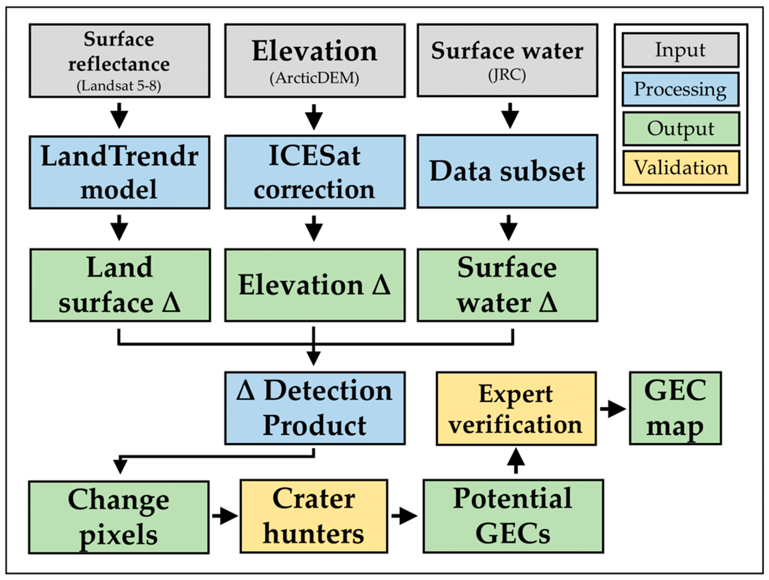
Figure 1. Summary of workflow for the change (∆) detection algorithm (CDA) and production of the GEC map.
Geosciences 11 00021 g001
Figure 2. Locations of gas emission craters (GEC) and change detection features (CDF) identified by the change detection algorithm (CDA). Magnitude of landscape change was derived from the change pixels (see Section 2.2).
Geosciences 11 00021 g002
Figure 3. Examples of types of land surface change in the Yamal-Gydan region that were detected by the change detection algorithm (CDA): upland thermokarst (a) with change pixels (b); lake shoreline erosion (c,d); lake drainage (e,f); and fluvial network change (g,h). Satellite imagery in the left and right columns are identical. Imagery in the right column includes colored pixels from the CDA. Imagery © 2020, DigitalGlobe.
Geosciences 11 00021 g003
Figure 4. Distribution of surface change pixel values (range = 0.098–1.62, n = 1.9 × 10⁹). Vertical lines connect change pixel values with corresponding GECs. CDF-2 is not shown because its land surface change values were omitted by the water mask.
Geosciences 11 00021 g004
Figure 5. Three GEC-like change detection features (CDF) identified using the change detection algorithm: CDF-1 (a), CDF-2 (b), and CDF-3 (c). Imagery © 2020, DigitalGlobe
Geosciences 11 00021 g005
Figure 6. Time-series of high-resolution satellite imagery showing the development of GEC-2 from July 2010 (top left image) to August 2020 (bottom center image). Image series shows the mound predecessor (a,b) prior to GEC formation (c), and subsequent lake formation and expansion (dh). Image on the bottom right shows a cluster of change pixels superimposed on the lake formed by GEC-2 (i). Chart at the bottom (j) shows the original trends and fitted trends (by LandTrendr) in Landsat-derived NDVI (scaled from −1000 to 1000), the breakpoint identified by LandTrendr, and corresponding trends in elevation extracted from the corrected ArcticDEM strips. Imagery © 2020, DigitalGlobe.
Geosciences 11 00021 g006
Figure 7. Time-series of high-resolution satellite imagery showing the development of CDF-2 from September 2011 (top left image) to July 2020 (bottom right image). Image series shows the mound predecessor (a), mound degradation (b), crater formation (c), and subsequent lake expansion (d). Graphs at the bottom (e) show the original trends and fitted trends (by LandTrendr) in Landsat-derived NDVI (left) (scaled from −1000 to 1000), breakpoints identified by LandTrendr, and trends in elevation (right; 2014–2017) extracted from the corrected ArcticDEM strips. Imagery © 2020, DigitalGlobe.
Geosciences 11 00021 g007
Table 1. Total area and change among vegetation and land cover categories defined by the circumpolar arctic vegetation map (CAVM) [27]. The list of detailed CAVM categories comprising each generalized category can be found in Table A2. Non-Arctic regions outside of the CAVM map (not reported) accounted for 188 km2 (0.1%) of the study area.
CAVM Category (Generalized)n CAVM
Categories Represented
Total (km2)Total Area (%)Total Change (km2)Change Proportion
Upland/non-wetland tundra5263,05980.511,5770.04
Wetland complex335,90211.030090.08
Water223,8497.316100.07
Mountains/barren terrain339431.24440.11
Table 2. Characteristics of gas emission craters (GECs) on the Yamal and Gydan peninsulas. CDF = change detection feature. Latitude (Lat) and longitude (Long) are reported in decimal degrees. ∆ = surface change value derived from the change detection algorithm (CDA). Approximate formation dates reported as month, when known, or a range of months/years. * No change pixels in area due to omission by water mask. 1 [24], 2 [25], 3 [17], 4 [16], 5 This study.
CraterAlternate GEC IDsLat
(DD)
Long
(DD)
Date FormedDiameter (m)Depth (m)CDA (∆) 5
GEC-1C1 169.971168.3703October 2013–April 2014 325–29 450–70 31.00
GEC-2C2 170.144668.4959September–October 2012 432–35 4-0.97
GEC-3C9 270.062569.0995October 2012–June 2013 435–37 4-0.48
AntGECC3 269.794675.0350September 2013 325–28 315–19 30.52
SeYkhGECC11 170.302071.7455June 2017 476–88 456 10.78
YeniGECC4 271.285981.9250---0.95
ErkutaGECC12 268.110769.55212016–201710–12200.54
CDF-1-69.843472.0637-18–30 5-0.44
CDF-2-70.067968.37692015 512–15 5-*
CDF-3-70.038868.68972011–2015 520–22 5-0.38
Publisher’s Note: MDPI stays neutral with regard to jurisdictional claims in published maps and institutional affiliations.