Abstract
Geotechnical seismic isolation (GSI) has emerged as a potential technique to mitigate the effects of earthquakes, with many applications to structural configurations, such as bridges and buildings. It consists of absorbing the seismic energy from the soil to the superstructure by interposing a superficial soil layer in order to reduce the accelerations that filter from the soil to the structure. This mitigation technique is particularly suitable in developing countries since GSIs are low-cost seismic isolation systems that through relatively simple manufacturing processes allow to safe costs and stimulate many applications. The presented study aimed to perform 3D numerical finite element models that overcome the previous contributions by performing several structural configurations. Several historical earthquakes are considered in this paper, and the results may be applied to drive general assessments of the technique in case of future seismic hazards.
1. Background
Seismic base isolation using natural materials is a relatively new technique [1,2] with historical applications for several structures (such as buildings and bridges) [3]. Traditional base isolation suffers some limitations mainly due to costs (installation and maintenance of the devices) and exploring new methodologies that allow cost saving is important especially for developing countries, as shown in Reference [4]. In this regard, applications that apply different materials, including rubber-soil mixtures (RSM), geofoam, and geosynthetics, have become more frequent. The mechanism at the base of such applications consists of dissipation of energy inside the soil and reducing the transmission of seismic forces to the superstructure.
The concept of geotechnical seismic isolation (GSI) was historically proposed by Reference [5] and has been applied in recent constructions of the Rio-Antirion Bridge in Greece [6], Vasco de Gama Bridge in Portugal [7], and the Izmit Bay Bridge in Turkey [8]. Other interesting applications consist of soil replacement by geofoam smooth synthetic liners [9,10,11,12,13], geomembranes/geotextiles [14,15,16,17,18], rocking isolation [19,20,21,22] and natural stone pebbles [23,24]. In particular, Reference [12] proposed seismic isolators made of kart tyres filled with recycled elastomeric materials, following a green and environmentally friendly approach and tested via horizontal tests with static and dynamic loadings. In particular, GSI technique has many novelties, if compared with the traditional base isolation. For example, tyres as filling materials are effective because their high-expected life and simple, low-cost, and environmentally friendly production processes [12]. Fiber Reinforced Bearings (FRBs) were found to be effective because of the absence of thick end-plates thus they have no need to be bonded to top and bottom support surfaces and their thin layers of fiber reinforcements are flexible in extension with little flexural rigidity [25]. Moreover, GSI can be validly applied for the developing countries where the design and construction of small and poorly constructed buildings in many urban areas do not provide an adequate level of structural safety against even moderate seismic events. In particular, past earthquakes suggested that introducing simple but reliable low-cost isolation devices would have reduced the number of damages, failures, economic costs, functionality interruptions and losses of lives [25].
GSI has been studied by following two main approaches. First, researchers conducted experimentally investigations [24,25,26,27,28,29,30,31]. In particular, Reference [24] assessed the efficiency of seismic base isolation using natural stone pebbles below the foundation by experimental shake table tests with the aim to propose practical applications in the construction of low-cost buildings and smaller bridges in seismically active regions. They applied four different inputs to stiff and medium-stiff buildings: one on rigid-base foundations and a model with a layer of stone pebbles under the foundations.
Secondly, numerical simulations were performed [32,33,34,35,36,37,38,39,40,41]. For example, Reference [36] applied a non-linear, inelastic model to test the proposed isolator made by tire-derived aggregate (TDA) Rubber, obtained from scrap tires which are shredded into small pieces. Their approach differed from the equivalent non-linear models available in the literature with that they simulated the performance of a simple structure subjected to a variety of actual seismic records. They demonstrated that rubber–soil mixture layer placed underneath a structure could reduce significantly the seismic demand on it by performing several simulations with nonlinear inelastic models, subjected to vertically propagating shear waves. Moreover, Reference [4] proposed a new, low-cost, seismic isolation strategy for developing countries consisting of a sand-rubber foundation layer by presenting a comprehensive static and dynamic experimental investigation of a wide spectrum of mechanical and geometrical properties of a deformable, granular sand-rubber layer. in Reference [42], the authors performed three-dimensional (3D) Finite Element (FE) model by using experimental data from four Modified Rectangular Fiber-Reinforced Elastomeric Isolators (MR-FREIs), based on geometric modifications to the plan loaded surface of the original FREIs that simultaneously altered both the horizontal and vertical performance of the isolator, including increased stresses and changes in pressure distributions.
Recently, Reference [43] proposed an innovative procedure based on the use of nanoindentation tests [44] consisting of coring a very small sample of rubber from a bearing and testing it with a nanoindenter to quantitatively estimating the current characteristics of elastomeric bearings, in conjunction with low implementation costs and influence on the isolating devices. They also conducted experimental tests that showed good agreement between the properties calculated with the proposed method and the ones obtained directly through traditional shear tests.
Overall, low-cost seismic isolation systems through relatively simple manufacturing process stimulate many applications, such as isolation of new structures (i.e., Reference [6,7,8]) or retrofits of existing ones (i.e., Reference [45]). In particular, Reference [37] developed a lumped-parameter analytical model for the dynamic analysis of GSI systems by proposing equivalent-linear stiffness and viscous damping coefficients along with rocking radiation damping coefficient for surface and embedded foundations. In Reference [45], unbounded fiber reinforced elastomeric isolators (UFREI) combined with ferrous shape memory alloy (SMA) wires were applied to base seismically isolate a historical masonry church located in the south part of Lombardia region, Northern Italy. Recently [46] proposed to implement GSI technique as a low-cost alternative for the conventional base isolation technique under a two storied residential apartment building in India.
In this background, the present paper aimed to develop the preliminary study [42], where the effects of GSI were assessed on bridge configurations (performed with equivalent 1 Degree of Freedom (1DOF) models) by performing tri-dimensional (3D) numerical models of low-rise buildings. The paper applies the open-source computational interface OpenSeesPL, implemented within the FE code OpenSees [47,48].
2. Case Study
This paper considers the previous results by Reference [38] that investigated the seismic response of low-rise to mid-rise residential buildings isolated with a RSM layer that leads to a general reduction of the parameters of the structure (i.e., floor accelerations). Similar conclusions were shown in Reference [41] that demonstrated the effectiveness of the use of a surface foundation layer (RSM) on the seismic response of reinforced concrete moment resisting frames, taking into account soil–structure interaction effects and considering the building’s height. The beneficial effects of GSI were object of the previous contribution of Reference [40] that assessed the role of Soil Structure Interaction (SSI) by varying soil deformability.
Developing such contribution, this paper aims to focus on the role of the structural flexibility by performing structural configurations with increasing number of floors and thus different dynamic characteristics. Figure 1 and Figure 2 show the 3D and the vertical views. Table 1 shows the characteristics of the considered benchmark structures (named S1, S2, and S3) and their longitudinal periods. In order to focus on structural flexibility, the effects of the soil were minimized by implementing a hard soil (named soil A) defined in Reference [40]. The properties of the GSI configurations (liner position: 0.50 m) are also based on the previous study by Reference [40].
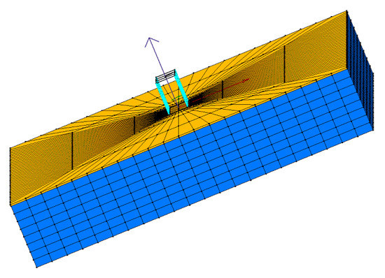
Figure 1.
Three-dimensional mesh: soil (blue); geotechnical seismic isolation (GSI) liner (yellow).
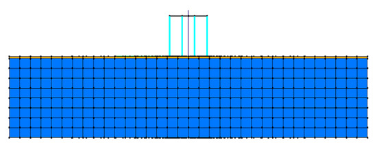
Figure 2.
Vertical view: soil (blue); GSI liner (yellow).

Table 1.
Structural characteristics.
In order to reproduce realistic scenarios, five historical earthquakes were considered (Figure 3 and Table 2); see Reference [40]) on the base of Eurocode prescriptions and applied along the x-axis (longitudinal direction). For all analyses, the Newmark transient integrator is used with c = 0.6 and = 0.3 (as already applied in Reference [40]). Stiffness and mass proportional damping is added with 2% equivalent viscous damping at 1 and 6 Hz, as already applied in Reference [48].
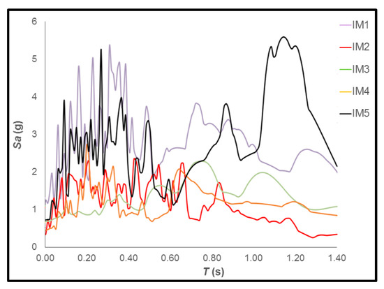
Figure 3.
Selected input motions [40].
Table 2.
Selected input motions (characteristics).
3. Finite Element Models
Finite Element Models were built with Opensees PL [47,48]. A total of 6 systems have been studied: three isolated configurations (named GSI1, GSI2, and GSI3) and three non-isolated structures (named S1, S2, and S3). Table 1 shows the characteristics of the structural configurations that were selected to have fundamental periods in the range of residential buildings, considering 3, 5, and 7 floors (floor height: 3.40 m, total heights: 10.20 m; 17.00 m and 23.80 m) and several values of H/B (1.38, 2.30, and 3.22), where H is the total height of the building and B the dimension of the foundation in the longitudinal direction. The structures have the same 4 × 3 column scheme (4 in longitudinal direction (8 m spaced) and 6 in the transversal direction (10 m spaced)), a shear-type behavior (with plan and vertical regularity) and seismic masses concentrated at each floor level. The structural configurations were assumed to be linear elastic and modeled with elastic-beam column elements (Table 3).
Table 3.
Elastic beam column element parameters.
The concrete shallow foundations (28.4 m × 34.4 m × 0.50 m) were considered as to be representative of recurrent typologies for residential buildings and performed as rigid by linking all the nodes at the base of the columns together and to boundaries (Figure 2), by applying equaldof [47,48]. Foundations were designed by calculating the eccentricity (the ratio between the overturning bending moment at the foundation level and the vertical forces) in the most detrimental condition of minimum vertical loads (gravity and seismic loads) and maximum bending moments. Foundations were modeled with a Pressure Independent Multiyield (see Reference [47,48]; Table 4) as an equivalent concrete non-linear hysteretic material with a Von Mises multi-surface kinematic plasticity model to simulate monotonic or cyclic response of materials in which shear behavior is insensitive to the confinement change. GSI configurations were embedded directly inside the liner superficial mesh and horizontal rigid beam-column links were set normal to the column longitudinal axis to simulate the interface between the column and GSI liner. The Pressure Independent Multiyield model [47,48] (Figure 4) was applied to model the GSI liner, and the calibration of several parameters (Table 5) was required. Some of them (such as the density, Poisson’s ratio) have little effect on the performance of GSI and were widely investigated in literature, as shown in Reference [38]. The other parameters (as shear modulus and cohesion) that are fundamental to define the characteristics of energy dissipation and shear strain deformation of the liner were herein based on the previous values assumed in Reference [40], since a specific experimental procedure would have been required a proper calibration.
Table 4.
Foundation.
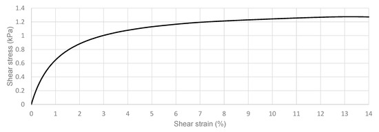
Figure 4.
GSI material backbone curve.
Table 5.
GSI liner and soil parameters.
The soil consists of a one-layer 30 m homogenous cohesive material with a 3D mesh (100 m × 75 m × 30 m) FE mesh composed of 2496 brickUP isoparametric 8-nodes elements with 2873 nodes (Figure 1), and it was built-up on the soil mesh calibrated and performed in Reference [40]. Penalty method was adopted for modeling the boundary conditions (tolerance: of 10−4), chosen as a compromise to be large enough to ensure strong constrain conditions but not too large to avoid problems associated with conditioning of the system of equations. Base boundaries (30 m depth) were considered rigid. Vertical direction (described by the 3rd DOF) was constrained in correspondence with all the boundaries (at the base and lateral), while longitudinal and transversal directions were left unconstrained in correspondence with the lateral boundaries to allow the shear deformations of the GSIs. The 3D meshes were defined by following the approach already adopted in Reference [49,50,51,52,53], and they were verified by comparing the accelerations at the surface levels of the soil meshes with the free field conditions at the edge of the mesh, and they were found to be identical.
4. Results
The 3D models can compute the performance of the entire systems (soil + GSI + structure) in realistic details by considering significant design parameters, such as maximum accelerations at the base of the structures and at various floors. Figure 5 shows the time histories of the longitudinal accelerations (at the base of the mesh, in correspondence with the bedrock) that can be compared with the accelerations that resulted for the isolated structural configurations (GSI1, GSI2, and GSI3, respectively, shown in Figure 6, Figure 7 and Figure 8). The reductions in the accelerations were possible since the inertial soil-structure interaction was minimized and did not play the relevant role that was shown in Reference [40]. In particular, it is worth noting that GSI efficiently reduced the accelerations at the base of the structure (reductions around 50% for S1 and S2 and around 70% for S3). These reductions depend on the friction force that is proportional to the weight of the structure and that leads the shear mechanism on which GSI behavior is based. Similar conclusions were shown in Reference [41] that demonstrated that the use of RSM layers is beneficial mainly for mid-rise and high-rise buildings.
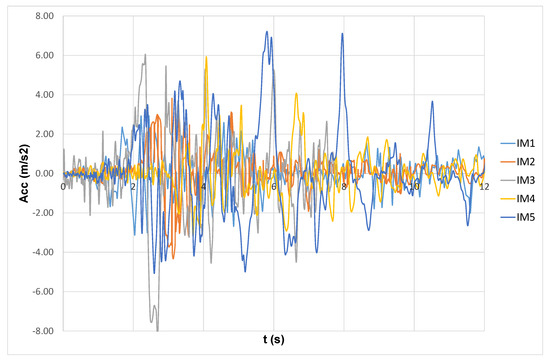
Figure 5.
Acceleration time histories at the bedrock.
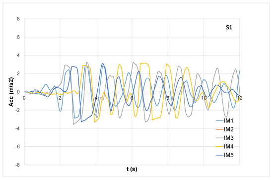
Figure 6.
Base acceleration (S1).
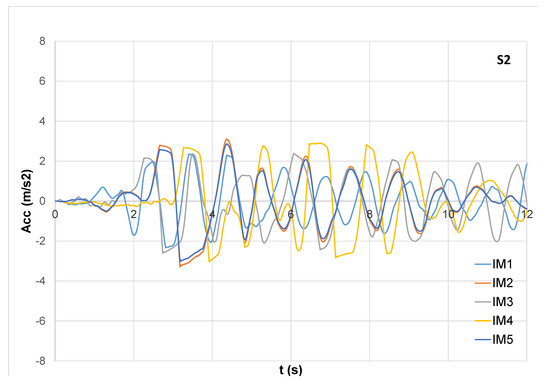
Figure 7.
Base acceleration (S2).
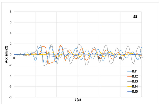
Figure 8.
Base acceleration (S3).
The reduction of the accelerations along the height of the building is the key parameter to assess the effectiveness of GSI, and the role of H/B ratio on the structural performance is assessed by calculating the significant parameters that describe the performance. In this regard, Figure 9, Figure 10, Figure 11, Figure 12 and Figure 13 show the maximum longitudinal accelerations along the height of the buildings in correspondence with the selected input motions. It is worth noting that, in some cases, the reduction of maximum acceleration occurs at a certain height and that this position along the height of the structure depends on the structural flexibility.
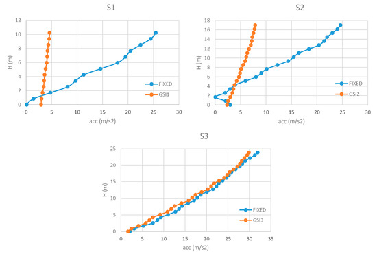
Figure 9.
Maximum accelerations along the height (IM1).
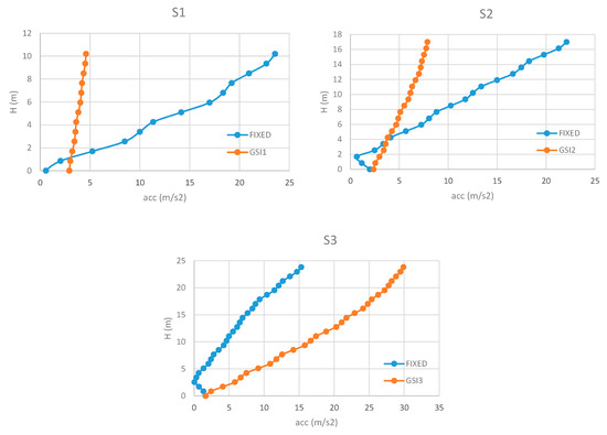
Figure 10.
Maximum accelerations along the height (IM2).
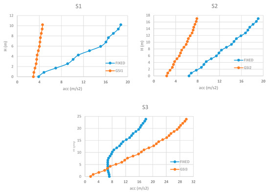
Figure 11.
Maximum accelerations along the height (IM3).
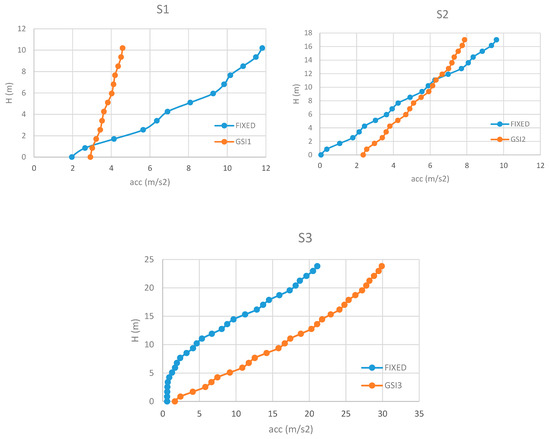
Figure 12.
Maximum accelerations along the height (IM4).
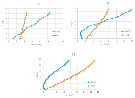
Figure 13.
Maximum accelerations along the height (IM5).
For S1, GSI reduces the maximum accelerations that remain relatively constant along the height of the structures. It is worth noting that GSI is shown to become efficient at 1–2 m from the base, with maximum reductions of the accelerations in correspondence with IM1 (around 5 times if compared with the fixed configuration; see Figure 9). Near the base, the values of the maximum accelerations are bigger when GSI is applied, except for IM3, because, in correspondence with the fundamental period of the structure (0.301 s), this input motion presents low values of pseudo-accelerations (see Figure 3).
For S2, GSI effectiveness is limited to the highest floors, while the lower parts suffer big accelerations depending on the stiffness of the columns. In this regard, it is worth noting that GSI cases show increases of the maximum accelerations at the base of the structures that can become even significantly bigger than those resulted for the fixed cases, in correspondence with IM4 and IM5 (Figure 12 and Figure 13). For IM3, the reduction of the accelerations increases with the height of the structure, with a maximum reduction of 2.24 at the top of the structure (Figure 11).
For S3, the results show that GSI is detrimental in correspondence with every motion except for IM1 (Figure 9), where no improvements occurred, confirming that application of base isolation should be limited to low- and medium-rise buildings since its efficiency is driven significantly by the superstructure flexibility, as historically recognized by Reference [54].
Moreover, the reduction of the accelerations along the height of the building was shown to depend on the mutual relation between the peak values of the input motion and the fundamental period of the structure. For example, S1 and S2 perform particularly well for IM3 since the fundamental periods (Table 1) are significantly far from the peak values of the input motion (around 0.75 s; see Figure 3). On the contrary, S3 has a fundamental period of 0.685 s (Table 1) that leads to the detrimental amplifications shown in Figure 11, due to dynamic mechanisms (i.e., resonance).
Table 6 shows the maximum displacements at the surface (z = 0.00m) for the three performed configurations and in correspondence with the selected input motions. These permanent deformations depends essentially on the shear mechanism that leads the behavior of GSI, since non-linear deformations of the ground were minimized by considering hard soil conditions (Table 5). It is worth noting that the displacements are not significantly influenced by the bearing pressures of the buildings (S1: 203 kPa; S2: 350 kPa; S3: 496 kPa) and that these values are similar to those calculated in Reference [40].
Table 6.
Maximum displacements at the surface (z = 0.00 m).
Overall, the performed 3D numerical simulations confirmed the importance of structural flexibility assessing the behavior of the entire system (hard soil + GSI layer + structure) in reducing the accelerations along the height of the building. The results demonstrated that, under the conditions investigated here, low-rise structures (S1) can experience more significant reductions of accelerations than the highest one (S3), confirming what was shown in Reference [38]. In addition, middle-rise buildings are shown to be more sensitive to eventual detrimental effects in correspondence with lower floors, and this needs to be considered in designing GSIs.
5. Conclusions
The paper investigated the effects of structural flexibility on GSI effectiveness by performing several 3D structural models built up with OpenSeesPL. The principal novelty consists of overcoming the previous contributions where only equivalent structures (single degree of freedom) were analyzed. The paper demonstrated GSI effectiveness in reducing the foundation input motions and improving the seismic response of low-rise to mid-rise residential buildings founded on a hard soil (minimizing the effects of soil deformability). The calculated time histories of accelerations along the height of the building confirmed that GSI tends to be more effective in reducing floor accelerations in case of low-rise buildings. The paper also showed that GSI is not always beneficial depending on the dynamic characteristics of the input motion in relation to the properties of the structure (mainly the fundamental periods). Even if the presented outcomes are limited to the considered conditions, they can potentially be helpful to take the structural slenderness into proper consideration during design procedures. Many aspects still need to be considered for this innovative technique, such as experimental calibration of GSI properties, durability of the isolation systems, and in-situ assessment procedures that will be object of future investigations.
Funding
This research received no external funding.
Conflicts of Interest
The authors declare no conflict of interest.
References
- Przewłócki, J.; Dardzinska, I.; Swinianski, J. Review of historical buildings’ foundations. Géotechnique 2005, 55, 363–372. [Google Scholar]
- Carpani, B. Base isolation from a historical perspective. In Proceedings of the 16th World Conference on Earthquake, Santiago, Chile, 9–13 January 2017. [Google Scholar]
- Kulukčija, S.; Humo, M.; Mandžić, E.; Mandžić, K.; Selimović, M. Existing historical foundation system of two old bridges from the Ottoman period in Bosnia and Herzegovina. In Proceedings of the Third International Congress on Construction, Cottbus, Germany, 20–24 May 2009. [Google Scholar]
- Tsiavos, A.; Alexander, N.; Diambra, A.; Ibraim, E.; Vardanega, P.J.; Gonzalez-Buelga, A.; Sextos, A.G. A sand-rubber deformable granular layer as a low-cost seismic isolation strategy in developing countries: Experimental investigation. Soil Dyn. Earthq. Eng. 2019, 125, 105731. [Google Scholar] [CrossRef]
- Tsang, H.H. Seismic isolation by rubber-soil mixtures for developing countries. Earthq. Eng. Struct. Dyn. 2007, 37, 283–303. [Google Scholar] [CrossRef]
- Pecker, A.; Prevost, J.H.; Dormieux, L. Analysis of pore pressure generation and dissipation in cohesionless materials during seismic loading. J. Earth. Eng. 2001, 5, 441–464. [Google Scholar] [CrossRef]
- Pecker, A. Aseismic foundation design process, lessons learned from two major projects: The Vasco de Gama and the Rion Antirion bridges. In Proceedings of the ACI International Conference on Seismic Bridge Design and Retrofit, La Jolla, CA, USA, 8–9 December 2003. [Google Scholar]
- Steenfelt, J.S.; Foged, B.; Augustesen, A.H. Izmit Bay bridge-geotechnical challenges and innovative solutions. Int. J. Brid. Eng. 2015, 3, 53–68. [Google Scholar]
- Azinović, B.; Koren, D.; Kilar, V. The seismic response of low-energy buildings founded on a thermal insulation layer—A parametric study. Eng. Struct. 2014, 81, 398–411. [Google Scholar] [CrossRef]
- Azinović, B.; Kilar, V.; Koren, D. Energy-efficient solution for the foundation of passive houses in earthquake-prone regions. Eng. Struct. 2016, 112, 133–145. [Google Scholar] [CrossRef]
- Azzam, W.; Ayeldeen, M.; El Siragy, M. Improving the structural stability during earthquakes using in-filled trench with EPS geofoam—Numerical study. Arab. J. Geosci. 2018, 11, 395. [Google Scholar] [CrossRef]
- Hadad, H.A.; Calabrese, A.; Strano, S.; Serino, G. A Base Isolation System for Developing Countries Using Discarded Tyres Filled with Elastomeric Recycled Materials. J. Earthq. Eng. 2016, 21, 246–266. [Google Scholar] [CrossRef]
- Karatzia, X.; Mylonakis, G. Geotechnical seismic isolation using eps geofoam around piles. In Proceedings of the 6th International Conference on Computational Methods in Structural Dynamics and Earthquake Engineering, Rhodes Island, Greece, 15–17 June 2017. [Google Scholar]
- Doudoumis, I.; Papadopoulos, P.; Papaliangas, T. Low-cost base isolation system on artificial soil layers with low shearing resistance. In Proceedings of the 12th European Conference on Earthquake Engineering, London, UK, 9–13 September 2002. [Google Scholar]
- Yegian, M.K.; Catan, M. Soil Isolation for Seismic Protection Using a Smooth Synthetic Liner. J. Geotech. Geoenviron. Eng. 2004, 130, 1131–1139. [Google Scholar]
- Yegian, M.K.; Kadakal, U. Foundation Isolation for Seismic Protection Using a Smooth Synthetic Liner. J. Geotech. Geoenviron. Eng. 2004, 130, 1121–1130. [Google Scholar]
- Nanda, R.P.; Shrikhande, M.; Agarwal, P. Effect of ground motion characteristics on the pure friction isolation system. Earthq. Struct. 2012, 3, 169–180. [Google Scholar] [CrossRef]
- Kalpakci, V.; Bonab, A.T.; Özkan, M.Y.; Gulerce, Z. Experimental evaluation of geomembrane/geotextile interface as base isolating system. Geosynth. Int. 2018, 25, 1–11. [Google Scholar] [CrossRef]
- Makris, N. A half-century of rocking isolation. Earthq. Struct. 2014, 7, 1187–1221. [Google Scholar] [CrossRef]
- Chung, Y.L.; Du, L.J.; Pan, H.H. Performance evaluation of a rocking steel column base equipped with asymmetrical resistance friction damper. Earthqu. Struct. 2019, 17, 49–61. [Google Scholar]
- Feng, R.; Chen, Y.; Cui, G. Dynamic response of post-tensioned rocking wall-moment frames under near-fault ground excitation. Earthqu. Struct. 2018, 15, 243–251. [Google Scholar]
- Wang, J.; He, J.X.; Yang, Q.; Yang, N. Study on mechanical behaviors of column foot joint in traditional timber structure. Earthqu. Struct. 2018, 66, 1–14. [Google Scholar]
- Banović, I.; Radnić, J.; Grgić, N. Geotechnical Seismic Isolation System Based on Sliding Mechanism Using Stone Pebble Layer: Shake-Table Experiments. Shock. Vib. 2019, 2019, 9346232. [Google Scholar] [CrossRef]
- Banović, I.; Radnić, J.; Grgić, N.; Matesan, D. The Use of Limestone Sand for the Seismic Base Isolation of Structures. Adv. Civ. Eng. 2018, 2018, 9734283. [Google Scholar] [CrossRef]
- Spizzuoco, M.; Calabrese, A.; Serino, G. Innovative low-cost recycled rubber–fiber reinforced isolator: Experimental tests and Finite Element Analyses. Eng. Struct. 2014, 76, 99–111. [Google Scholar] [CrossRef]
- Anastasopoulos, I.; Loli, M.; Georgarakos, T.; Drosos, V. Shaking Table Testing of Rocking—Isolated Bridge Pier on Sand. J. Earthq. Eng. 2012, 17, 1–32. [Google Scholar] [CrossRef]
- Xiong, W.; Li, Y. Seismic isolation using granulated tire-soil mixtures for less-developed regions: Experimental validation. Earthq. Eng. Struct. Dyn. 2013, 42. [Google Scholar] [CrossRef]
- Xiong, W.; Yan, M.R.; Li, Y.Z. Geotechnical Seismic Isolation System—Further Experimental Study. Appl. Mech. Mater. 2014, 580, 1490–1493. [Google Scholar] [CrossRef]
- Patil, S.J.; Reddy, G.; Shivshankar, R.; Babu, R.; Jayalekshmi, B.; Kumar, B. Seismic base isolation for structures using river sand. Earthq. Struct. 2016, 10, 829–847. [Google Scholar] [CrossRef]
- Radnić, J.; Grgić, N.; Matešan, D.; Baloević, G. Shake table testing of reinforced concrete columns with different layout size of foundation. Mater. Werkst. 2015, 46, 348–367. [Google Scholar] [CrossRef]
- Tehrani, F.M.; Hasani, A. Behaviour of Iranian low rise buildings on sliding base to earthquake excitation. In Proceedings of the 11th World Conference on Earthquake Engineering, Acapulco, Mexico, 23–28 June 1996; p. 1433. [Google Scholar]
- Mavronicola, E.; Komodromos, P.; Charmpis, D.C. Numerical Investigation of Potential Usage of Rubber-Soil Mixtures as a Distributed Seismic Isolation Approach. In Proceedings of the Tenth International Conference on Computational Structures Technology, Valencia, Spain, 14–17 September 2010. [Google Scholar]
- Panjamani, A.; Ramegowda, M.D.; Divyesh, R. Low cost damping scheme for low to medium rise buildings using rubber soil mixtures. Jpn. Geotech. Soc. Spec. Publ. 2015, 3, 24–28. [Google Scholar] [CrossRef][Green Version]
- Xiao, H.; Butterworth, J.W.; Larkin, T. Low technology techniques for seismic isolation. In Proceedings of the 2004 NZSEE Conference, Rototua, New Zealand, 19–21 March 2004. [Google Scholar]
- Bandyopadhyay, S.; Sengupta, A.; Reddy, G.R. Performance of sand and shredded rubber tire mixture as a natural base isolator for earthquake protection. Earthq. Eng. Eng. Vib. 2015, 14, 683–693. [Google Scholar] [CrossRef]
- Brunet, S.; De La Llera, J.; Kausel, E. Non-linear modeling of seismic isolation systems made of recycled tire-rubber. Soil Dyn. Earthq. Eng. 2016, 85, 134–145. [Google Scholar] [CrossRef]
- Tsang, H.-H.; Pitilakis, K. Mechanism of geotechnical seismic isolation system: Analytical modeling. Soil Dyn. Earthq. Eng. 2019, 122, 171–184. [Google Scholar] [CrossRef]
- Tsang, H.-H.; Lo, S.H.; Xu, X.; Sheikh, M.N. Seismic isolation for low-to-medium-rise buildings using granulated rubber-soil mixtures: Numerical study. Earthq. Eng. Struct. Dyn. 2012, 41, 2009–2024. [Google Scholar] [CrossRef]
- Zhao, X.; Zhang, Q.; Zhang, Q.; He, J. Numerical study on seismic isolation effect of gravel cushion. In Proceedings of the 7th International Conference on Discrete Element Methods, Dalian, China, 1–4 August 2016. [Google Scholar]
- Forcellini, D. Assessment on geotechnical seismic isolation (GSI) on bridge configurations. Innov. Infrastruct. Solutions 2017, 2, 760. [Google Scholar] [CrossRef]
- Pitilakis, K.; Karapetrou, S.; Tsagdi, K. Numerical investigation of the seismic response of RC buildings on soil replaced with rubber–sand mixtures. Soil Dyn. Earthq. Eng. 2015, 79, 237–252. [Google Scholar] [CrossRef]
- Van Engelen, N.C.; Osgooei, P.M.; Tait, M.J.; Konstantinidis, D. Experimental and finite element study on the compression properties of Modified Rectangular Fiber-Reinforced Elastomeric Isolators (MR-FREIs). Eng. Struct. 2014, 74, 52–64. [Google Scholar] [CrossRef]
- Rossi, E.; Sebastiani, M.; Gigliotti, R.; D’Amato, M. An Innovative Procedure for the In-situ Characterization of Elastomeric Bearings by Using Nanoindentation Test. Int. J. Arch. Herit. 2020, 1–13. [Google Scholar] [CrossRef]
- Oliver, W.C.; Pharr, G. Nanoindentation in materials research: Past, present, and future. MRS Bull. 2010, 35, 897–907. [Google Scholar] [CrossRef]
- Habieb, A.B.; Valente, M.; Milani, G. Hybrid seismic base isolation of a historical masonry church using unbonded fiber reinforced elastomeric isolators and shape memory alloy wires. Eng. Struct. 2019, 196, 109281. [Google Scholar] [CrossRef]
- Dhanya, J.S.; Boominathan, A.; Banerjee, S. Response of low-rise building with geotechnical seismic isolation system. Soil Dyn. Earthquake Eng. 2020, 136, 106187. [Google Scholar] [CrossRef]
- Lu, J.; Elgamal, A.; Yang, Z. OpenSeesPL: 3D Lateral Pile-Ground Interaction, User Manual, Beta 1.0. Available online: http://soilquake.net/openseespl/ (accessed on 5 June 2020).
- Mazzoni, S.; McKenna, F.; Scott, M.H.; Fenves, G.L. Open System for Earthquake Engineering Simulation User Command-Language Manual. Available online: http://opensees.berkeley.edu/OpenSees/manuals/usermanual (accessed on 5 June 2020).
- Forcellini, D. Seismic assessment of a benchmark based isolated ordinary building with soil structure interaction. Bull. Earthq. Eng. 2017, 16, 2021–2042. [Google Scholar] [CrossRef]
- Forcellini, D. Cost assessment of isolation technique applied to a benchmark bridge with soil structure interaction. Bull. Earthq. Eng. 2016, 15, 51–69. [Google Scholar] [CrossRef]
- Forcellini, D. Numerical simulations of liquefaction on an ordinary building during Italian (20 May 2012) earthquake. Bull. Earthq. Eng. 2019, 17, 4797–4823. [Google Scholar] [CrossRef]
- Forcellini, D. Soil-structure interaction analyses of shallow-founded structures on a potential-liquefiable soil deposit. Soil Dyn. Earthq. Eng. 2020, 133, 106108. [Google Scholar] [CrossRef]
- Mina, D.; Forcellini, D. Soil–structure interaction assessment of the 23 November 1980 Irpinia-Basilicata earthquake. Geosciences 2020, 10, 152. [Google Scholar] [CrossRef]
- Skinner, R.I.; Robinson, W.H.; McVerry, G.H. An Introduction to Seismic Isolation; John Willey & Sons: New York, NY, USA, 1994. [Google Scholar]


© 2020 by the author. Licensee MDPI, Basel, Switzerland. This article is an open access article distributed under the terms and conditions of the Creative Commons Attribution (CC BY) license (http://creativecommons.org/licenses/by/4.0/).