Article

Effects of Thinner Compliant Electrodes on Self-Clearability of Dielectric Elastomer Actuators

1
Department of Mechanical Engineering, National Chiao Tung University, Hsinchu 30010, Taiwan
2
Temasek Laboratories, Nanyang Technological University, Singapore 637553, Singapore
3
School of Mechanical and Aerospace Engineering, Nanyang Technological University, Singapore 639798, Singapore
*
Author to whom correspondence should be addressed.
Actuators 2020, 9(4), 121; https://doi.org/10.3390/act9040121
Submission received: 2 October 2020 / Revised: 20 November 2020 / Accepted: 24 November 2020 / Published: 26 November 2020
(This article belongs to the Special Issue Dielectric Elastomer Actuators (DEAs))

Abstract

:
A metalized plastic capacitor stands a higher chance to clear faults when embodied with thinner electrodes. However, it is not clear whether the same thickness effect applies to carbon-based compliant electrodes in clearing the defects in dielectric elastomer actuators (DEA). This experimental study showed that charcoal-powder compliant electrodes act like fuses and current limiters to successfully clear the defects of an acrylic dielectric elastomer actuator, provided a very thin electrode coating. For example, DEAs with 3 μ m thick (average) charcoal-powder electrodes fast cleared faults and sustained high breakdown strength (300 to 400 MV/m), but the ones with thicker charcoal-powder electrodes (30 μ m thick on average) succumbed to persisting breakdowns in a weaker electric field (200 to 300 MV/m). Thermo-gravitational analysis and differential scanning calorimetry showed that dielectric elastomer (3M VHB F9473PC) started to ignite at 350 C, and charcoal powders (Mungyo charcoal pastel MP-12CP) started burning above 450 C. This confirmed that flash ignition and its damping of charcoal powder is possible only with a very thin electrode coating relative to acrylic elastomer substrate thickness. Too thick of a charcoal-powder coating could lead to the spread of burning beyond the initial flash point, and incomplete burning that punctures the dielectric layer but shorts across opposite electrodes. With this insight, one can design self-clearable electrodes to improve the dielectric strength of dielectric elastomer actuators.

Graphical Abstract

1. Introduction

Dielectric elastomer actuators can act as artificial muscles for driving bio-inspired robots [1,2], yet their performance still pales as compared to natural muscles; it is limited by dielectric breakdown which depends on properties and designs of both dielectric systems and electrodes. Causes of dielectric breakdown [3,4] include: (1) partial discharge [3,5] of air void in dielectrics; (2) electromechanical breakdown [3,4,6,7,8], which happens at a weak spot where the dielectric elastomer membrane locally collapses under critical electrostatic pressure; and (3) electrothermal breakdown [3,9,10,11,12], which happens at a hot weak spot where local resistive heating burns through and punctures the dielectric elastomer membrane. Among the causes that fail acrylic dielectric elastomer actuators [4,13], partial discharge of the air void happens in relatively weak electric fields of around 34 MV/m [13] while electromechanical and electrothermal breakdowns happen in stronger electric fields in the order of 100 to 500 MV/m [13]. Fatal failures happen if a dielectric elastomer membrane is subjected to local puncturing and permanent electrical shorting [3,9,10,11].
The fault tolerance of dielectric elastomer actuators can be improved by delaying dielectric puncturing and electrical shorting. Methods of inhibiting dielectric punctures include dielectric oil immersion [13,14,15,16] and dielectric gel encapsulation [10,17], both of which act as an oxygen barrier to make the dielectric elastomer thermally more stable against thermal degradation under local resistive heating. Meanwhile, electrical short can be avoided or delayed to stronger fields by using self-clearable electrode materials. Defects in the dielectric elastomer capacitor can be isolated electrically by vaporizing or oxidizing the electrode materials next to the defects. This self-clearing mechanism is similar to "fuse" vaporization that saves a plastic capacitor from permanent failure during a burn-in test. Examples of self-clearable electrode materials include single walled carbon nanotubes [18,19,20], reduced graphite nanoplatelets [21], fluffy charcoal powder [22], and silver nanometric films [23,24]. However, defect clearing in dielectric elastomer actuators was unsuccessful with multiwalled carbon nanotubes [25,26] and other common compliant electrode materials, such as carbon black [27].
Why can single-walled-carbon-nanotube electrodes [18] be cleared in the event of dielectric breakdown but multiwalled-carbon-nanotube ones cannot [25,26]? A complete isolation of the defect renders it an electrical open circuit (see Figure 1). However, incomplete burning will leave a conductive path or shorting path next to the dielectric puncture (see Figure 1c). Flash ignition [18,28] of single walled carbon nanotubes in a nanometric coating with ample air supply could help complete burning, so could fluffy charcoal dust [22] and graphite nanoplates [21] with their large surface areas per unit mass. However, to successfully clear the defect in the dielectric actuator, the ignition of electrode materials must be stopped from spreading. This is possible through limiting the fuel of an ignitable nanometric electrode coating and simultaneous damping by a large heat sink of a relatively cool dielectric elastomer substrate. This explanation agrees with the experimental observation reported by Shaw [14] that a metalized capacitor stands a higher chance of self-clearing with thinner metallic electrodes. The same thickness effect of the electrode is expected to improve the fault tolerance of dielectric elastomer actuator. However, it is not clear how thin the electrodes should be relative to dielectric layers to successfully clear the faults in dielectrics.
To answer these questions about self clearing of a capacitive device, we characterized the thermal stability and ignition temperatures acrylic dielectric elastomer and charcoal-powder electrodes. Next, we investigated the influences of the thickness of charcoal-powder compliant electrodes on dielectric elastomer activation and dielectric strength. This work showed highly resistive charcoal-powder compliant electrodes enabling the dielectric elastomer actuator to survive burn-in test. As a result, the actuator with self-clearable electrodes can sustain a higher voltage post repeated premature failure until the electrode resistance becomes too high for charging the capacitive actuator.

2. Mechanism of Self-Clearing

Here, we propose a mechanism to explain the stochastic phenomenon of dielectric breakdowns and the clearing of defects. Let us consider a dielectric elastomer actuator with compliant electrodes subjected to high voltages (strong electric field). Figure 1 postulates the possible chain effects of various failure modes in dielectric elastomer actuator with the support by theory and experimental observations, which will be elaborated in later sections. If there was a defect at a local weak spot which thinned down to a local membrane thickness t thinner than the nominal thickness, premature failure of dielectric elastomer could happen below the nominal critical field E c of electromechanical instability following [3,29]:
E b = V b t < E c = Y ϵ r ϵ 0 ,
where E b is the breakdown field, V b is the breakdown voltage, Y and ϵ r are Young’s modulus and dielectric constant of dielectric elastomer, and ϵ 0 is the air permittivity. There, the electric field is stronger than the nominal applied field due to the positive effect of thinning down. Then, the air void is subjected to a stronger electrostatic field and higher field concentration due to lower dielectric constant relative to the dielectric matrix following the interface condition for normal electrical displacement [3,29]:
E b , a i r = ϵ r E b .
Hence, the air void is more prone to partial discharge as compared to dielectrics. The occurrence of partial discharge heats up the dielectric media next to the air void, forming a heat affected zone and consequently reducing the local volume resistivity. Next, this leads to increased leakage current I l e a k and consequently increased resistive heating following
P l e a k = V I l e a k = V 2 R l e a k ,
if the soft capacitor is subjected to constant voltage activation.
Partial discharge at air voids may be the flash point (see Figure 1e(iii)), but its escalation to electrothermal breakdown depends on the applied electrical field, heat source, and sink. The heat source could be flash ignition and resistive heating of dielectric or electrodes, while the heat sink is the cooler part of dielectrics (outside heat affected zone). In the case of thermal runaway (see Figure 1e(v)), a dielectric was punctured electro-thermally when local resistive heating exceeded the capacity of heat sink such that the dielectric temperature at the weak spot eventually reached the degradation point. The severity of leakage current provides a measure of temperature rise and its positive feedback on reduced volume resistivity at the defect, which was modeled as a hot pin here. Then, the hot pin resistance follows:
R l e a k = V I l e a k ,
which is smaller than the nominal resistance for healthy parts of dielectric elastomer. The determination of dielectric resistivity at the hot pin follows: ρ h = R l e a k ( π r h 2 ) / t I , where r h is the radius of the hot pin, and t I is the nominal dielectric thickness next to the dielectric puncture where pre-stress was released. According to Klein’s model [10,30], temperature of the hot spot can be inferred from the correlation law: T h = ln ( ρ h / ρ 0 ) / a with ρ 0 being the extrapolated dielectric resistivity at 0 K and a being the index coefficient for an exponential decay function following [10].
Will a hot pin where leakage current passes be burnt hollow and become a pinhole? This is very likely if leak-induced resistive heating P l e a k is very fast and concentrated through the hot pin of tiny radius, leading to a quick rise in temperature. According to a hot spot model [11], dielectric puncture happens to a hot pin (of radius r h ) when the resistive heating reaches the degradation temperature T d , exceeding the heat dissipation by conduction off the heat affected zone of radius r a :
P l e a k > > 2 π k t ( T d T a ) ln ( r a / r h ) ,
where k is thermal conductivity of heat affected zone (i.e., dielectric elastomer) and T a is the ambient temperature, i.e., for the cool part of dielectric elastomer. Post mortem examination can measure the radius of pinhole r h , while a thermogram of persisting breakdown can show the radius r a of heat affected zone. The current limit of power supply determined the energy available to puncture to cause the dielectric breakdown and puncture. However, the size of hot spot and flame point depends on the available power relative to natural cooling and solid heat condition. This argument will be confirmed by the growth of dielectric puncture and flame size observed from the persisting breakdown of a DEA with thicker charcoal-powder electrodes.
Incomplete burning of the dielectric can lead to permanent shorting with a conductive trace along the puncture wall (see Figure 1e(vii)). Such a conductive trace could be a carbon remnant of not-fully-burnt acrylic dielectric or reflow of conductive grease or particles from electrode materials. Complete burning of dielectric and electrode materials on the defect can ensure electrical isolation (see Figure 1e(viii)) of the defect from the healthy part of soft capacitor. To help explain this self-clearing mechanism in short, we also proposed a circuit model consisting of fuse elements that represent parts of self-clearable electrodes and capacitor elements that represent parts of dielectric elastomer actuator (see Figure 1e(viii) left).
Some questions still remain about details of the self-clearing mechanism. The first question is about which component materials of the actuator ignite first. Do the dielectric elastomer substrate or self-clearable electrodes ignite first? The second question is how thick the electrodes will be in order to delay the spread of flash ignition and dielectric puncture. To answer these questions, we measured the ignition temperature and energy generation for both dielectric elastomer and electrode materials. To validate whether the dielectric elastomer substrate can act as the heat sink to damp out flash, we compared the heat capacities of dielectric and electrode layers.

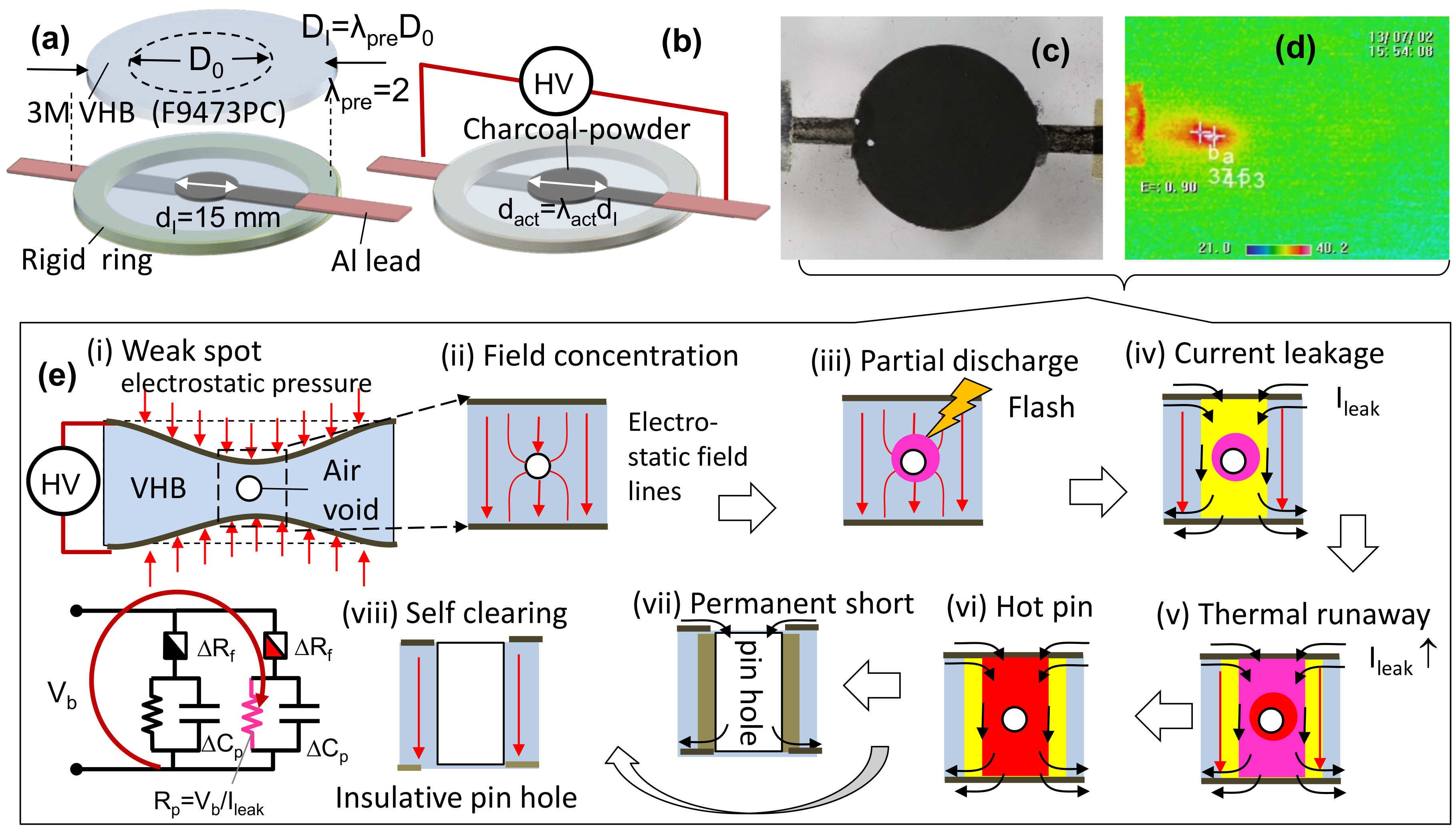
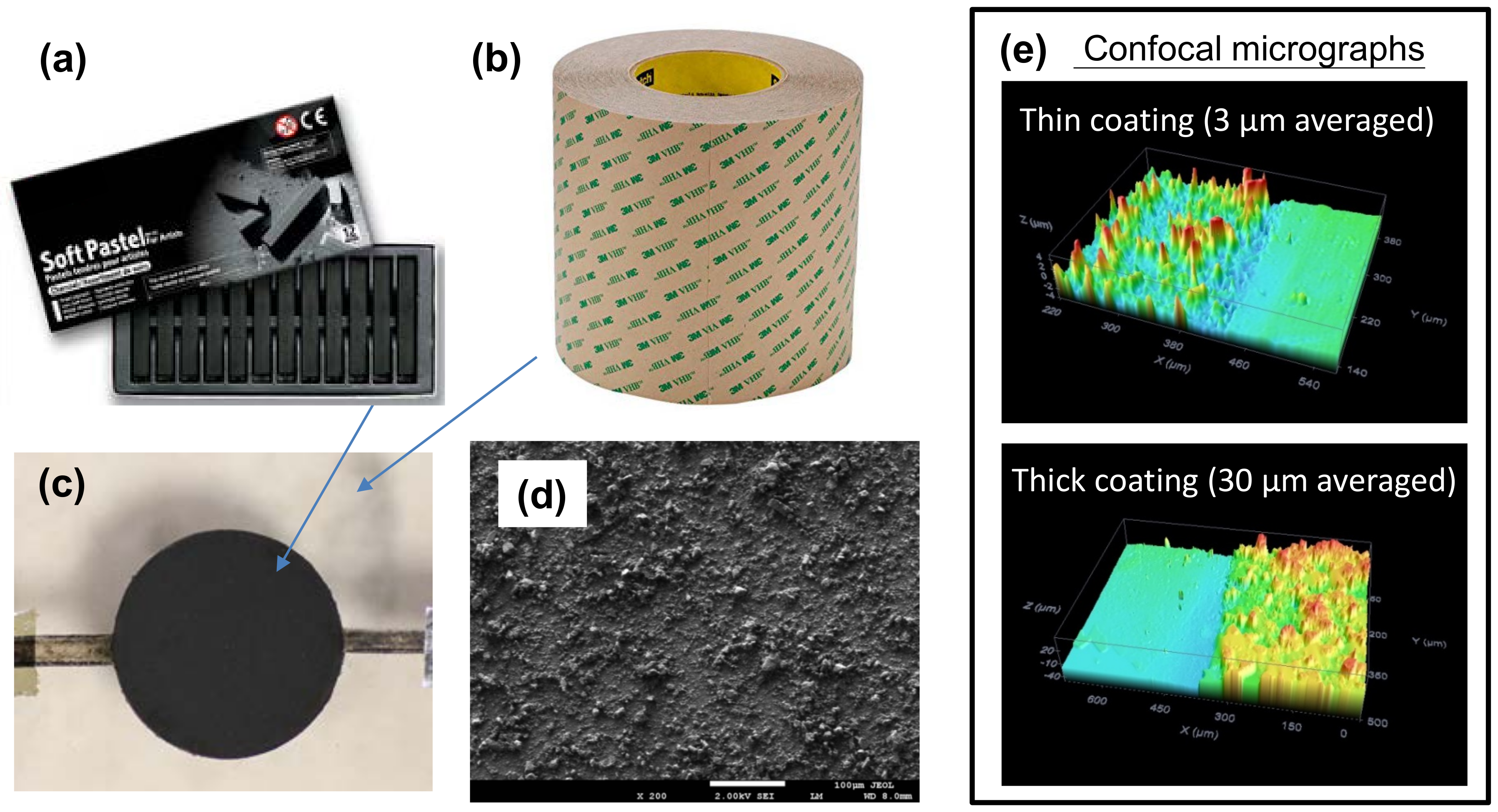
3. Materials and Methods

This section discusses the material and methods for investigating the failure mechanisms and self-clearability of dielectric elastomer actuators. Electrode materials and thickness were varied so as to show their impacts on self-clearing of the capacitive actuator. Resistors and dielectric elastomer actuators were prepared and tested—i.e., three samples for each electrode type and electrode thickness. Except the thermomechanical analyses, the stretch-resistor test and electromechanical tests were performed at room temperature (25 C) in an air-conditioned laboratory with 65% relative humidity.
First, we measured the weight loss and ignition of dielectric and electrode materials using simultaneous thermogravimetry–differential scanning calorimetry (TA Instruments, SDT Q7600, Singapore). Then for measuring weight loss and heat absorption, the sample was subjected to a temperature ramp. This investigation will reveal the thermal stability of constituent materials. Second, we measured the stretchability of electrode materials and the dependence of its electrical resistance on coating thickness; the stretchability and resistance values of electrode materials dictate the actuation and current limit. Thirdly, we performed the electromechanical tests of dielectric elastomer actuators. During the tests, we simultaneously measured the leakage current and applied voltage across the capacitive actuator. During the dielectric elastomer activation, visual observation of sparks was assisted by a thermogram that identified the hot spot of a localized breakdown. Here, an infrared camera (NEC Thermo Shot F30W with a pixel size of 156 μ m by 156 μ m) was used to capture thermograms at each voltage step during the ramp activation.
Charcoal pastels (see Figure 2) are commonly used for art, but are also used to make compliant electrodes in pulverized powder form. Our preliminary works [22] showed charcoal powder (prepared by pulverization of the charcoal pastel) serves as a cheap self-clearable compliant electrode for an acrylic dielectric elastomer actuator. Here, we developed a technique to control the coating thickness of charcoal powder on the acrylic adhesive tape. Charcoal powders were prepared from a pastel stick of drawing charcoal (Mungyo Co Ltd, Korea, MP-12CP) by manual pulverization using a mortar and pestle. Transfer smearing was applied to obtain fine coating on the adhesive substrate, in the same manner as transfer printing. First, we used a rubber-gloved finger to further ground and smear the charcoal powders on a piece of paper substrate. Second, we transferred the fine charcoal powder on the rubber glove to the adhesive target of elastomeric substrate. The transferred powders can be spread more uniformly by further smearing on the substrate. A scanning electron micrograph in Figure 2d shows the surface morphology; two optical confocal micrographs showed a thin coating (3 μ m averaged) and a thick coating (30 μ m averaged), which were obtained by tapping and smearing once and smearing-only once respectively. The tapping and smearing three times yielded a 6 μ m averaged thick coating. The coating thickness was measured by non-contact confocal microscopy (Keyence, Japan, VK-X200 Series 3D laser scanning confocal microscope) by averaging the step height of charcoal coating next to a blank substrate.
To be useful for compliant electrodes, an electrode coating of charcoal powder needs to remain electrically conductive while being stretched on an elastomeric substrate. Here, the sample of compliant electrode was the coating of carbon powder on a strip of adhesive foam tape (3M VHB 4905). To prevent the stress concentration and tear at the clamp edge, the sample under tensile test was made of a 0.5 mm thick substrate of VHB 4905 tape rather than 0.26 mm thick VHB F9473PC tape; conductive coating thickness was controlled by transfer smearing. The strip of elastomer substrate was 25.4 mm wide, 76.2 mm long, and 0.5 mm thick initially. The conductive coating was at the middle of the strip, having a square shape of 25.4 mm sides. A tensile tester (Instron, United States, Instron model 5565) was used to pull the sample strip by moving one of the two clamped ends at a rate of 3 mm/minute. Then, the resistance change of the stretched coating was measured using a digital multimeter (Agilent, United States, DMM 34410A). The maximum stretchability of the resistor was taken at the value where the resistance hit the 1.5 G Ω limit readable by the digital multimeter. As the focus was to show the high resistance of the current limiter, we just measured the film electrical resistance but did not go deeper than surface resistivity. Later experiments will show the film electrical resistance, i.e., R f ( λ L ) , increases with increasing stretch due to the increasing separation of conductive particles. Then, the electrode stretch ratio λ L is defined as the ratio of the stretched length L f to undeformed length L f , 0 .
The actuator under testing was a dielectric elastomer actuator which consisted of a pre-stretched dielectric elastomer membrane sandwiched by a pair of charcoal-powder electrodes. The dielectric elastomer membrane had a square shape of 25 mm side; it was prepared by pre-stretching an acrylic foam tape (3M VHB F9473PC of 260 μ m thick) [23,31,32]. equi-biaxially for 2 times by 2 times. Here, a relatively moderate pre-stretch ratio was used to avoid the membrane creep and rupture under high pre-stretch [23,32]. The pre-stretched membrane was kept taut by a rigid acrylic frame with inner square hole of 50 by 50 mm. The charcoal-powder electrodes were in a circular shape of 15 mm in diameter; it was prepared by powder tapping and smearing on the adhesive substrate of dielectric membrane through a Teflon stencil mask. The electrical lead to the charcoal-powder compliant electrodes was aluminum foil, with improved contact by silver grease (Chemtronics, United States, CW7100) [33]. The coating thickness was controlled by the amount of tapping and smearing; excess powders were shaken off. For comparison, a reference actuator was prepared by using conductive silver grease (Chemtronics, United States, CW71000) as compliant electrodes, which was applied by brushing on the adhesive substrate.
Next, we performed electromechanical tests of dielectric elastomer actuators, three samples for each electrode type and each electrode thickness. A high voltage supply (Trek Inc, United States, Trek model 610E) was used to activate the capacitive actuators by a voltage ramp, stepwise (typically at a 30 s time step) until the ultimate dielectric breakdown. The high voltage supply was pre-set with a 20 μ A current limit to prevent the surge of leakage current during dielectric breakdown. In instances of flash or partial discharge, the voltage ramp was suspended. Then, the driving voltage was held constant until partial discharge was cleared. Afterwards, the voltage ramp was continued higher until the ultimate dielectric breakdown. During the ramp activation, the driving voltage and current were monitored continuously. A computer and NI digital acquisition card (National Instruments, NI DAQ 6009) were used to directly log the voltage monitor of high voltage supply, while a digital multi-meter (Agilent, United States, model DMM 34410) was used as the interface for measuring the leakage current.
A digital camera (Canon, Japan, EOS 55D) with a micro lens (Tamron, Japan, AF 90 mm F/2.8 Di SP A/M 1:1) was used to take the voltage induced area expansion of capacitive actuator. The voltage induced area strain was calculated as
s A = A a c t A I 1 = λ A 1 ,
where the active area ratio λ A = A a c t / A I is equal to the square of diametral stretch ratio, following A a c t / A I = ( d a c t / d I ) 2 = λ d 2 . As such, the capacitive actuator under high voltage V activation is thinned down to be t 0 / λ A under the electrostatic pressure. Then, the true electric field is calculated as:
E = V t = V t I t I t a c t = V t I λ A
where t I and t a c t are the initial and active thicknesses of the capacitive actuator. The active thickness ratio can be related to the active areal ratio on the assumption of volume conservation A I t I = A a c t t a c t .

4. Results and Discussion

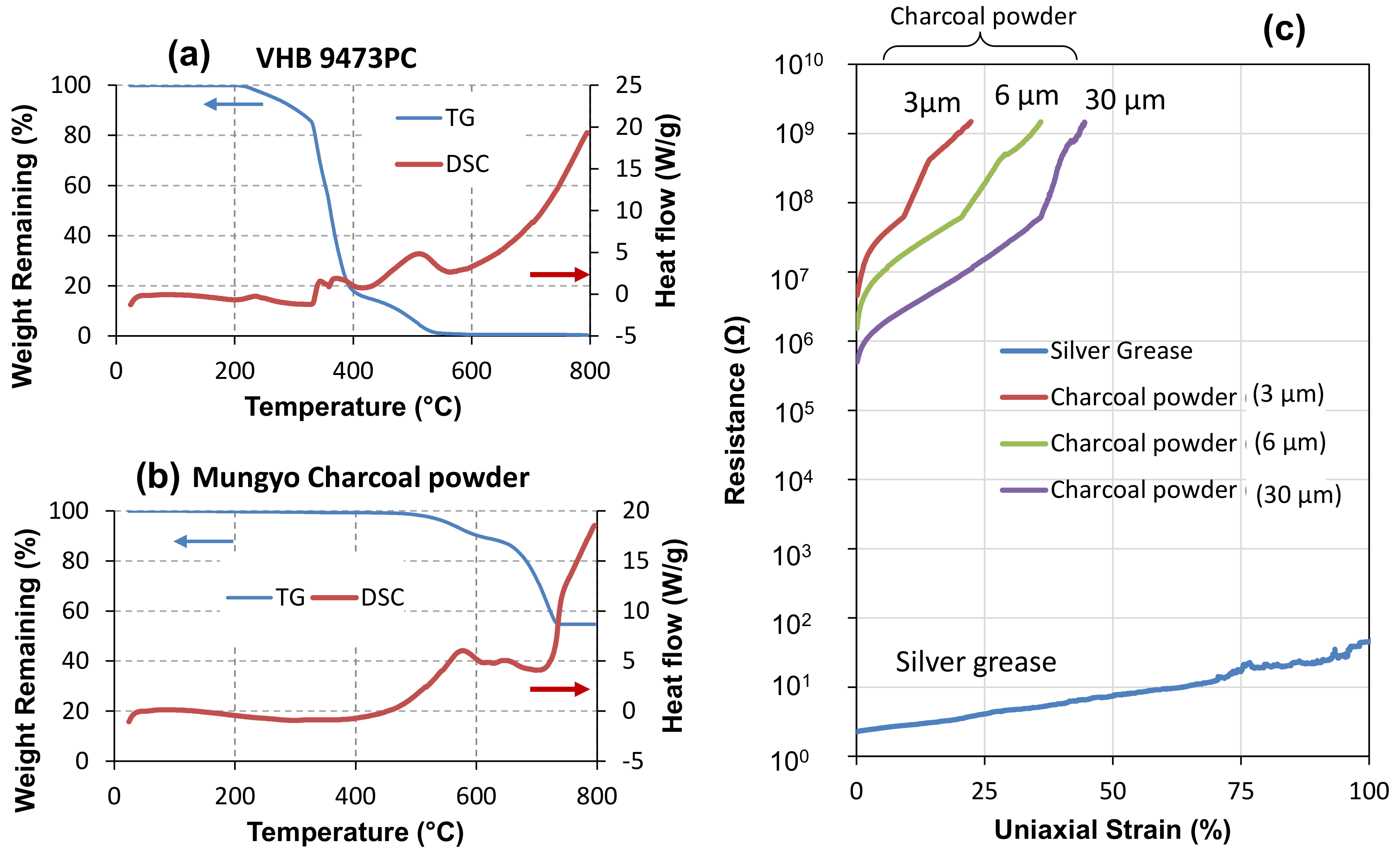
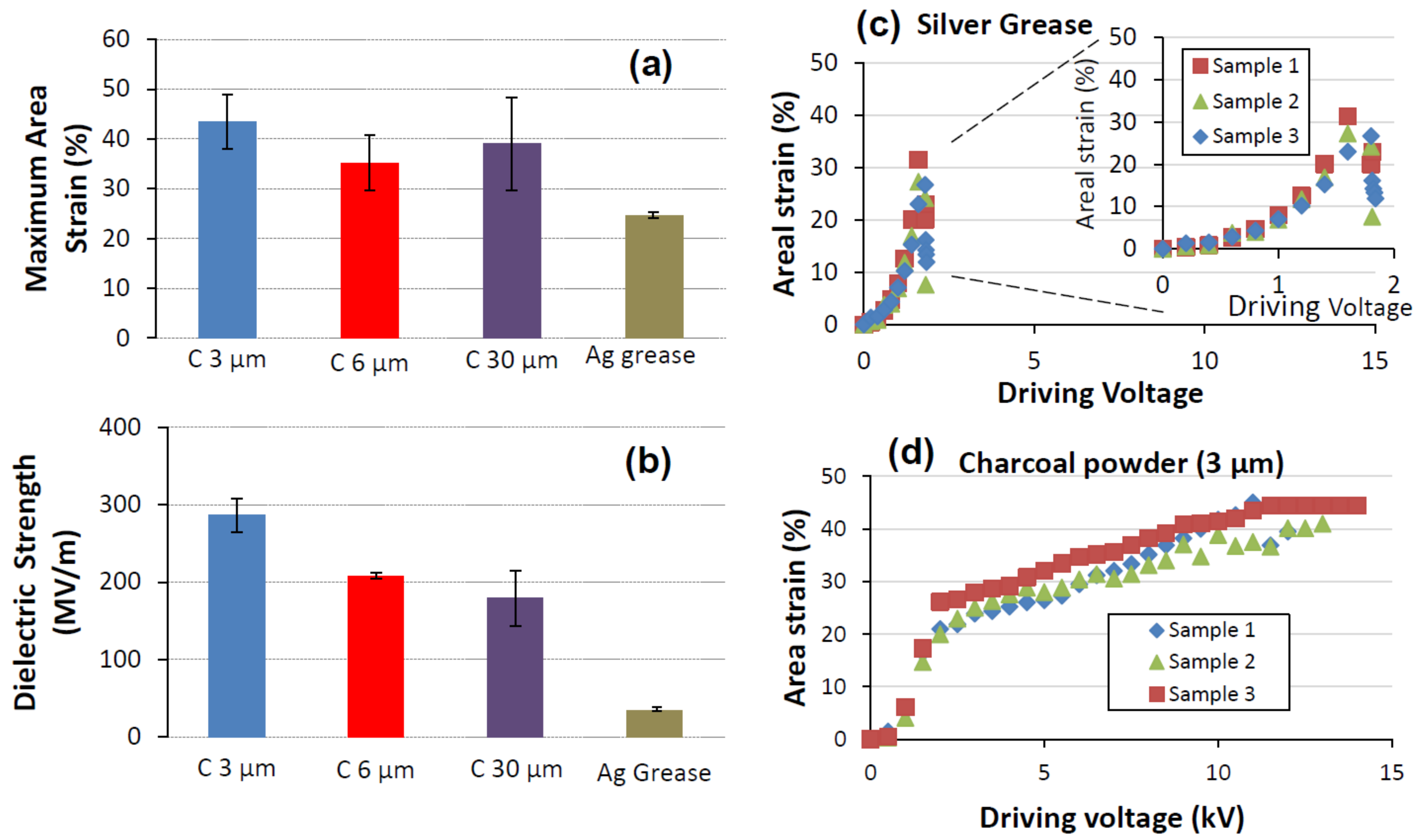
4.1. Material Characterization

First, we the tested thermal stability of VHB and charcoal powders using simultaneous thermogravimetry–differential scanning calorimetry. The tests were done at an air flow of 100.0 mL/min. Figure 3a,b shows that acrylic dielectric elastomer was ignited at 350 C in air flow while the ignition of charcoal-powder started from 450 C. In a typical device with a 65 μ m thick dielectric layer and very thin charcoal-powder electrodes (e.g., 3 μ m), the dielectric layer has much higher thermal capacitance and generates more heat once ignited (according to Figure 3a,b) than the surface conductive coating. According to thermo-physical properties of Table 1 and the calculation from (65 μ m × 2010 J/kg/k)/(3 μ m × 710 J/kg/k), heat capacitance of dielectric layer is 61.3 times that of the electrodes. This suggests that a flashover (partial discharge in air) within the dielectric layer could subsequently spread to ignite the burning of charcoal. Once the electrode material next to the defect was burnt off completely, there was no leakage current to fuel the burn of dielectric. Hence, the flash fire could be extinguished by the cooler substrate. This, however, suggests the opposite outcome with thick electrode coating (e.g., 30 μ m × 2) comparable to dielectric layer thickness. Then, the thicker and more conductive coatings of electrodes pass more leakage current to burn a pinhole across the dielectric layer. They are less ready to be completely burnt off given the power supply. Hence, dielectric breakdown persists with dielectric puncture growing in size. Subsequent experiments prove this projection.
Electrical resistance measurement shows the charcoal-powder coating is highly resistive in the range of mega-ohms. Figure 3c shows that uniaxial stretch can greatly increase the resistance of the carbon-powder coating, by two to three orders of magnitude, for not more than 50% stretch. The increased resistance of the stretched coating is due to increasing separation among the conductive charcoal dust. A thicker coating is more conductive and it can be stretched more until the loss of conductivity (at measurement limit of 1.5 G Ω ). For example, the initial resistance of carbon powder coating was 4.57 M Ω for a 3 μ m thick coating, but it was smaller at 0.5 M Ω for a 30 μ m thick coating. The maximum stretch was 22% strain for a 3 μ m thick coating, but it was larger at 50% strain for the 30 μ m thick coating. In comparison, silver grease electrode shows a much smaller initial resistance of 2.2 Ω ; it is highly stretchable and conductive due to fluidic nature. For example, the resistance of 120% stretched electrode remained low, rising little to 62 Ω .

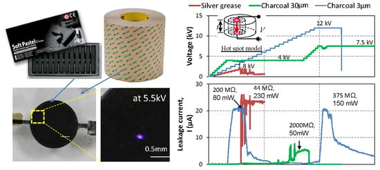
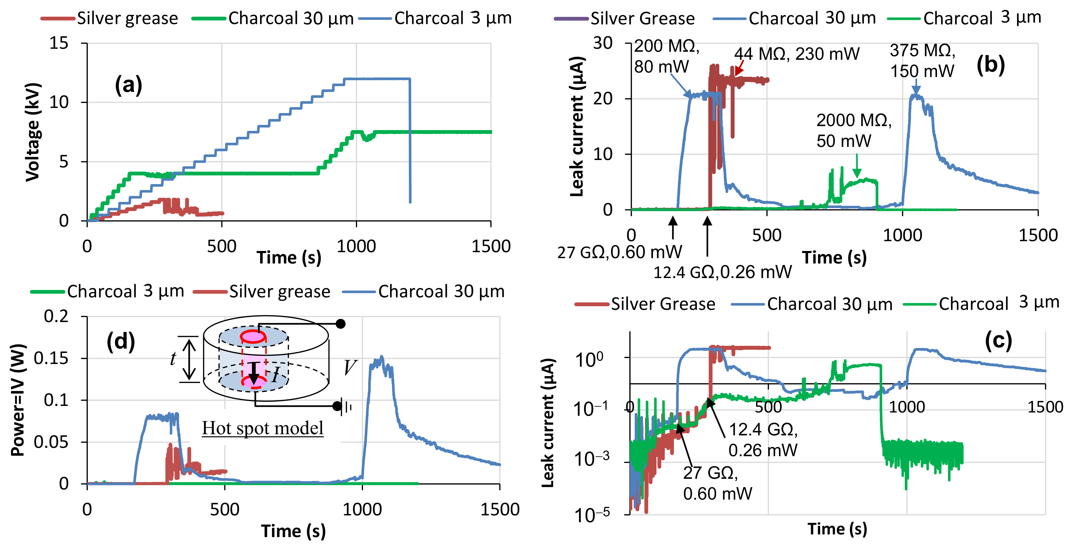
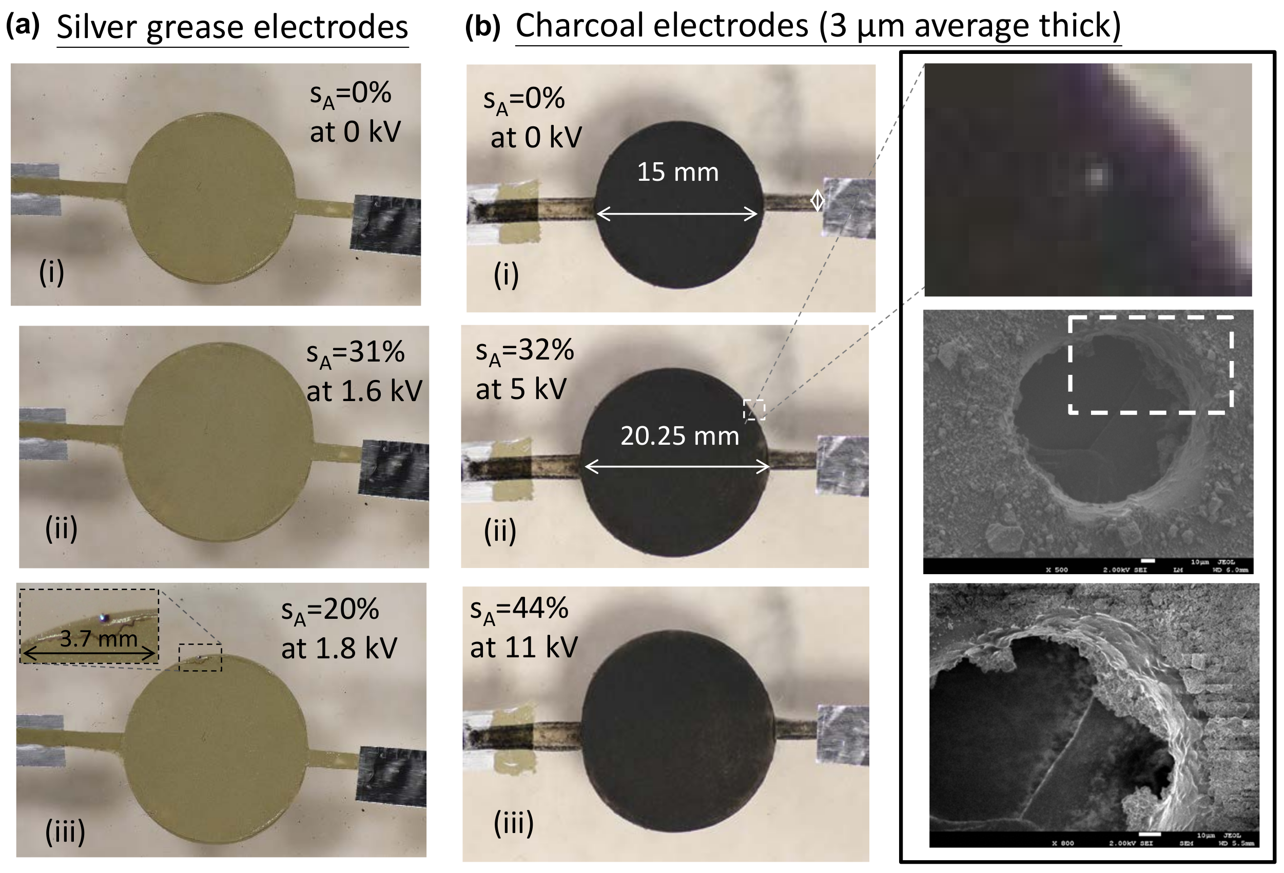
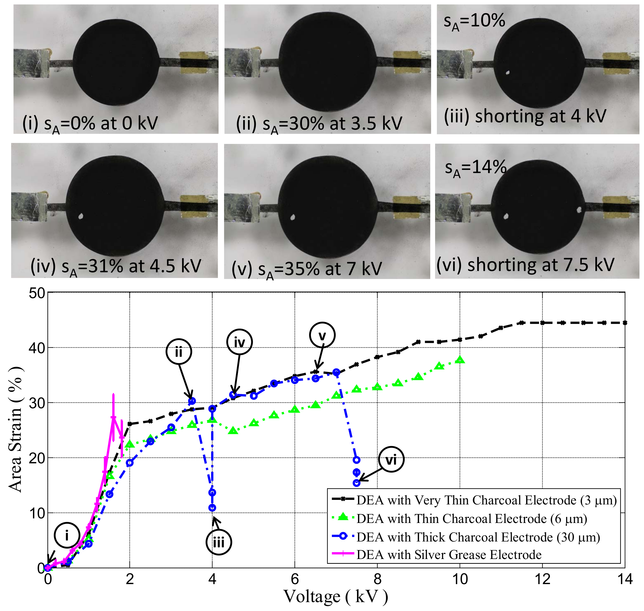
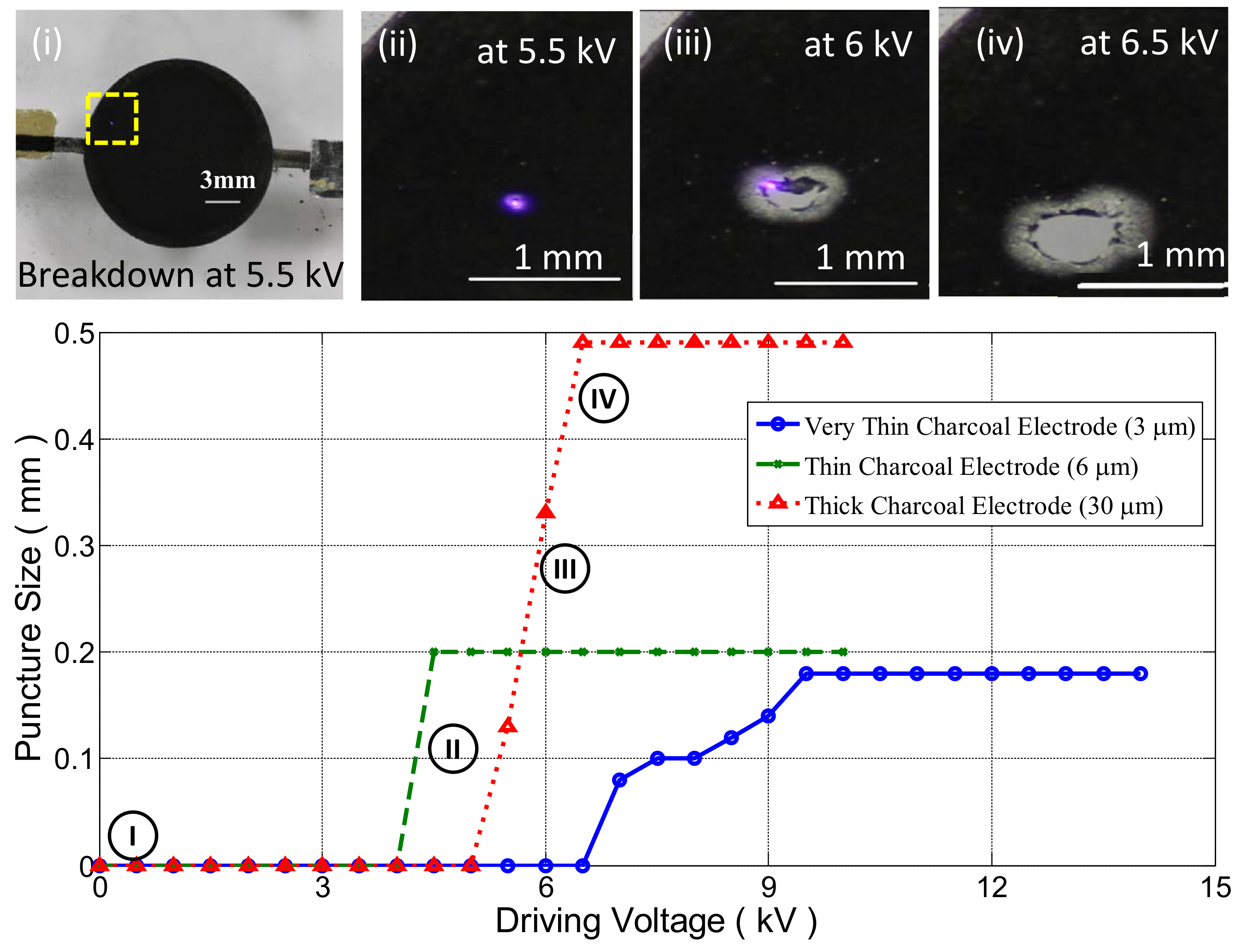
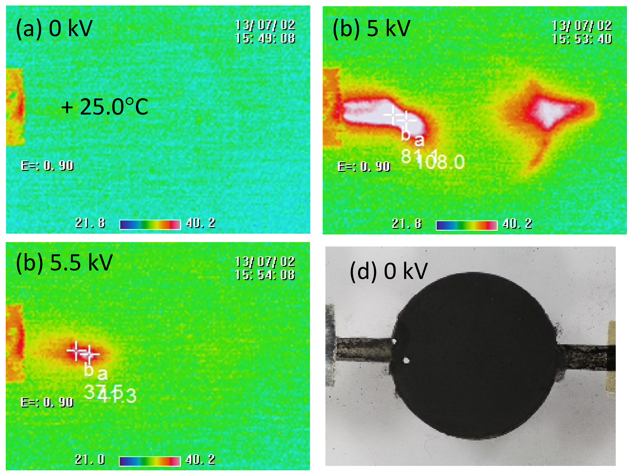
4.2. Device Characterization

Electromechanical testing of dielectric elastomer actuators showed that electrode material and thickness matter to dielectric breakdown and actuation performance. Figure 4 shows the actuators with charcoal-powder electrodes were found to sustain a higher breakdown voltage and actuated more than the ones with silver grease electrodes. Figure 4a,b shows that a thicker coating of charcoal-powder electrodes has negative impacts on both dielectric strength and maximum actuation. For example, for the actuators with thin charcoal-powder electrodes (3 μ m thick on average), the maximum breakdown field was 372 MV/m on average and the maximum active area strain was 43% on average. In contrast, for the actuator with thicker charcoal-powder electrodes (30 μ m thick on average), the maximum breakdown field was 278 MV/m and the maximum active area strain was 39%. In comparison, the ones with silver grease electrodes at best produced 31% areal strain at 1.6 kV (corresponding to an electric field 32.2 MV/m) prior to electrical breakdown.
A closer look in Figure 4 and Figure 5 of electromechanical activation reveals that dielectric elastomer actuators behave like perfect insulators below 2 kV. Figure 4c,d shows that the active area strain increased in proportion to the square of driving electric field. Beyond that threshold, the dielectric elastomer actuators behave in a “lossy” way with the leakage current jumping from very small sub-micron-amperes to a few micro-amperes (see Figure 5c). This leads to the tapering of actuation with further increasing voltage (see Figure 4c,d).
Next we investigated the impacts of electrode material and thickness on dielectric breakdown. Figure 5 shows the voltage, leakage current, and power for driving each type of dielectric elastomer actuator under a ramped activation with a pre-set 20 μ A current limit. The actuators tested and monitored were the ones with silver grease electrodes, the ones with 3 μ m thick charcoal-powder electrodes, and the ones with 30 μ m thick charcoal-powder electrodes. Among them, only the ones with very thin charcoal-powder electrodes (3 μ m thick) were self-clearable quickly so that their drives could be ramped up all the way to 12 kV prior to fatal failure. The other two actuators with more conductive electrodes showed less successes in self-clearing. For example, the one with more conductive electrodes of 30 μ m thick charcoal-powder electrodes succumbed to failure twice, a non-fatal one at 4 kV taking 6 min to clear, and a near-fatal one at 7.5 kV. Due to higher electrode conductance and persisting ignition, the leakage current during 4 kV failure surged to 24–25 μ A, beyond the pre-set current limit of 20 μ A. On the other hand, the near-fatal failure at 7.5 KV was not completely cleared; the leakage current remained in the range of several micro-amperes. In comparison, the actuator with silver grease electrodes immediately succumbed to permanent failure at a smaller driving voltage of 1.8 kV. The failed actuator was never recovered as silver grease might have flowed and filled up the pin hole. Figure 6a(iii) shows a light bluish flame on the silver grease electrodes during the terminal failure; this indicated relative high temperature at the small defective spot.
The severity of a local breakdown through a pinhole can be measured in terms of heating power and resistance (calculated respectively following Equations (3) and (4)) due to leakage current, as labeled in Figure 5b–d. The actuator with silver-grease electrodes was subjected to highest resistive heating at the least pinhole resistance, whereas the one with thin charcoal-powder electrodes was subjected to the least resistive heating at the highest pinhole resistance. Thicker charcoal electrodes (i.e., with reduced electrode resistance) lead to persisting breakdowns and the most severe resistive heating at small pinhole resistance during dielectric breakdown. According to the Klein and hot-spot model [10,11,30], a lower pinhole resistance reflects a higher temperature of the local thermal runaway.
Figure 6 and Figure 7 show the incidents of breakdowns that happened during ramp activation of the actuators. A breakdown could happen at the weakest spot, which becomes red hot under resistive heating by a surge of leakage current. The actuation decreased with voltage drop during breakdown, but recovered to be high once the breakdown was cleared. Once the device was self-cleared, it can sustain a higher voltage and will encounter the next breakdown at the next weakest spot. For example, Figure 6b(i–iii) shows that a sample of dielectric elastomer actuator with 3 μ m thick charcoal-powder electrodes being recovered from non-fatal 5 kV breakdown and sustained higher driving voltage up to 11 kV to generate 44% areal strain. Figure 7(i–vi) shows a DEA with 30 μ m charcoal-powder electrodes being recovered froma 4 kV non-fatal breakdown but succumbed to a 7.5 kV shorting.
During high voltage activation of dielectric elastomer, dielectric breakdown persisted long with the spread of flame and growth of the dielectric puncture. Figure 8 shows an actuator (with a 30 μ m thick charcoal electrodes) subjected to a voltage ramp from 5.5 to 6.5 kV. A purplish spark started a small spot at 5.5 kV, burning off the defective spot of VHB and neighboring charcoal powder. The burn was incomplete, and eventually white ash was left on the remaining VHB membrane. The purplish spark does not increase in size with growing puncture. This suggests the dielectric burn being fueled by limited power supply following Equation (5). In comparison, the actuator with thinner charcoal-powder electrodes did not show as much growth of dielectric puncture due to higher electrode resistance that further limited the current surge during dielectric breakdown. Those experimental results proved that resistive charcoal-powder electrode could act as the current limiter during non-fatal dielectric breakdown and thus suppress the pin hole formation.
During dielectric breakdown, a thermogram can identify a tiny localized breakdown as a hot spot not possibly visualized by an optical camera or eyes. Figure 9 shows thermograms of a typical dielectric elastomer actuator with thick charcoal-powder electrodes. At 25 C room temperature, the thermogram in Figure 9a shows a rather uniform temperature distribution over the inactivated charcoal-powder electrode (30 μ m thick averaged). Figure 9b shows two coincident localized breakdowns at 5 kV with hot spots of 81.1 C and 108 C appearing next to the left lead. The actuator was activated to higher voltage to 5.5 kV when the defects were cleared. Then, temperatures of the cleared defective spots decreased down to 40.13 C but not back to the room temperature due to small leakage current. Thermogram in Figure 9d shows the narrow electrical lead of charcoal powder being subjected to higher resistive heating as compared to the larger active area, where the electrostatic pressure was applied across the dielectric elastomer membrane. This problem of resistive heating near the lead can be alleviated by widening the lead, as we did with graphite powder electrode, as we reported in reference [10,11].

5. Conclusions

This study shows that the bulk of acrylic elastomer substrate carries more heat capacity at a lower ignition temperature as compared to charcoal-powder coating; its flash ignition can fuel the burning of electrodes of higher ignition temperatures. Acrylic DEAs with charcoal-powder compliant electrodes were found to survive multiple partial breakdowns, provided the electrode materials next to the breakdown spot were cleared. It was found that compliant electrodes based on very thin coatings (3 μ m) of charcoal powders could be cleared fast by oxidation next to the breakdown spot. It serves as a fuse and current limiter to isolate the defect from the healthy parts of the dielectric. However, thicker charcoal-powder compliant electrodes were less ready to be completely burnt; they took longer to clearly grow dielectric punctures. In short, the breakdown strength of a VHB DEA generally increases with decreasing electrode thickness (i.e., increasing electrode resistance). With this insight, one can design compliant electrodes for improving the dielectric strength and actuation of DEAs.

Author Contributions

G.-K.L., L.-L.S., and S.-L.C. conceived the ideas and designed the study. L.-L.S. and S.-L.C. designed and performed all experiments. L.-L.S. and G.-K.L. analyzed data. G.-K.L. derived theoretical models. G.-K.L. and L.-L.S. wrote the manuscript. All authors discussed the results and revised the manuscript. All authors have read and agreed to the published version of the manuscript.

Funding

The corresponding author G.K.L. acknowledges the support by the Ministry of Science and Technology of Taiwan (grant 108-2218-E-009-058-MY3).

Acknowledgments

The first and second authors are with the School of Mechanical and Aerospace Engineering, Nanyang Technological University, Singapore.

Conflicts of Interest

The authors declare no conflict of interest.

References

  1. Pelrine, R.; Kornbluh, R.; Pei, Q.; Joseph, J. High-speed electrically actuated elastomers with strain greater than 100%. Science 2000, 287, 836–839. [Google Scholar] [CrossRef] [PubMed]
  2. Shintake, J.; Cacucciolo, V.; Floreano, D.; Shea, H. Soft robotic grippers. Adv. Mater. 2018, 30, 1707035. [Google Scholar] [CrossRef] [PubMed] [Green Version]
  3. Dissado, L.A.; Fothergill, J.C. Electrical Degradation and Breakdown in Polymers; IET: London, UK, 1992; Volume 9. [Google Scholar]
  4. Plante, J.S.; Dubowsky, S. Large-scale failure modes of dielectric elastomer actuators. Int. J. Solids Struct. 2006, 43, 7727–7751. [Google Scholar] [CrossRef] [Green Version]
  5. Muffoletto, D.; Martinez, A.; Burke, K.; Zirnheld, J. Electrode composition and partial discharges and their role in the breakdown of dielectric elastomer films. IEEE Trans. Dielectr. Electr. Insul. 2015, 22, 1756–1762. [Google Scholar] [CrossRef]
  6. Stark, K.; Garton, C. Electric strength of irradiated polythene. Nature 1955, 176, 1225–1226. [Google Scholar] [CrossRef]
  7. Huang, J.; Shian, S.; Diebold, R.M.; Suo, Z.; Clarke, D.R. The thickness and stretch dependence of the electrical breakdown strength of an acrylic dielectric elastomer. Appl. Phys. Lett. 2012, 101, 122905. [Google Scholar] [CrossRef] [Green Version]
  8. Chen, F.; Liu, K.; Wang, Y.; Zou, J.; Gu, G.; Zhu, X. Automatic design of soft dielectric elastomer actuators with optimal spatial electric fields. IEEE Trans. Robot. 2019, 35, 1150–1165. [Google Scholar] [CrossRef] [Green Version]
  9. Gisby, T.; Xie, S.; Calius, E.; Anderson, I. Leakage current as a predictor of failure in dielectric elastomer actuators. Electroactive Polymer Actuators and Devices (EAPAD) 2010. In Proceedings of the International Society for Optics and Photonics, San Diego, CA, USA, 8–11 March 2010; Volume 7642, p. 764213. [Google Scholar]
  10. La, T.G.; Lau, G.K. Inhibiting electro-thermal breakdown of acrylic dielectric elastomer actuators by dielectric gel coating. Appl. Phys. Lett. 2016, 108, 012903. [Google Scholar] [CrossRef]
  11. Lau, G.K.; La, T.G.; Foong, E.S.W.; Shrestha, M. Stronger multilayer acrylic dielectric elastomer actuators with silicone gel coatings. Smart Mater. Struct. 2016, 25, 125006. [Google Scholar] [CrossRef]
  12. Christensen, L.R.; Hassager, O.; Skov, A.L. Electro-Thermal model of thermal breakdown in multilayered dielectric elastomers. AIChE J. 2019, 65, 859–864. [Google Scholar]
  13. La, T.G.; Lau, G.K.; Shiau, L.L.; Tan, A.W.Y. Muscle-like high-stress dielectric elastomer actuators with oil capsules. Smart Mater. Struct. 2014, 23, 105006. [Google Scholar] [CrossRef]
  14. Shaw, D.; Cichanowski, S.; Yializis, A. A changing capacitor technology-failure mechanisms and design innovations. IEEE Trans. Electr. Insul. 1981, 16, 399–413. [Google Scholar] [CrossRef]
  15. La, T.G.; Lau, G.K. Very high dielectric strength for dielectric elastomer actuators in liquid dielectric immersion. Appl. Phys. Lett. 2013, 102, 192905. [Google Scholar] [CrossRef]
  16. Acome, E.; Mitchell, S.; Morrissey, T.; Emmett, M.; Benjamin, C.; King, M.; Radakovitz, M.; Keplinger, C. Hydraulically amplified self-healing electrostatic actuators with muscle-like performance. Science 2018, 359, 61–65. [Google Scholar] [CrossRef] [PubMed] [Green Version]
  17. Finis, G.; Claudi, A. On the dielectric breakdown behavior of silicone gel under various stress conditions. IEEE Trans. Dielectr. Electr. Insul. 2007, 14, 487–494. [Google Scholar] [CrossRef]
  18. Yuan, W.; Hu, L.; Yu, Z.; Lam, T.; Biggs, J.; Ha, S.M.; Xi, D.; Chen, B.; Senesky, M.K.; Grüner, G.; et al. Fault-tolerant dielectric elastomer actuators using single-walled carbon nanotube electrodes. Adv. Mater. 2008, 20, 621–625. [Google Scholar] [CrossRef]
  19. Yuan, W.; Brochu, P.; Ha, S.M.; Pei, Q. Dielectric oil coated single-walled carbon nanotube electrodes for stable, large-strain actuation with dielectric elastomers. Sensors Actuators Phys. 2009, 155, 278–284. [Google Scholar] [CrossRef]
  20. Stoyanov, H.; Brochu, P.; Niu, X.; Lai, C.; Yun, S.; Pei, Q. Long lifetime, fault-tolerant freestanding actuators based on a silicone dielectric elastomer and self-clearing carbon nanotube compliant electrodes. RSC Adv. 2013, 3, 2272–2278. [Google Scholar] [CrossRef]
  21. Michel, S.; Chu, B.T.; Grimm, S.; Nüesch, F.A.; Borgschulte, A.; Opris, D.M. Self-healing electrodes for dielectric elastomer actuators. J. Mater. Chem. 2012, 22, 20736–20741. [Google Scholar] [CrossRef]
  22. Lau, G.K.; Chua, S.L.; Shiau, L.L.; Tan, A.W.Y. Self-clearing dielectric elastomer actuators using charcoal-powder electrodes. Electroactive Polymer Actuators and Devices (EAPAD) 2012. In Proceedings of the International Society for Optics and Photonics, San Diego, CA, USA, 12–15 March 2012; Volume 8340, p. 834016. [Google Scholar]
  23. Hsien Low, S.; Lynn Shiau, L.; Lau, G.K. Large actuation and high dielectric strength in metallized dielectric elastomer actuators. Appl. Phys. Lett. 2012, 100, 182901. [Google Scholar] [CrossRef]
  24. Low, S.H.; Lau, G.K. Bi-axially crumpled silver thin-film electrodes for dielectric elastomer actuators. Smart Mater. Struct. 2014, 23, 125021. [Google Scholar] [CrossRef]
  25. Chua, S.L.; Neo, X.H.; Lau, G.K. Multi-walled carbon nanotubes (MWCNT) as compliant electrodes for dielectric elastomer actuators. Electroactive Polymer Actuators and Devices (EAPAD) 2011. In Proceedings of the International Society for Optics and Photonics, San Diego, CA, USA, 7–10 March 2011; Volume 7976, p. 79760V. [Google Scholar]
  26. Baechler, C.; Gardin, S.; Abuhimd, H.; Kovacs, G. Inkjet printed multiwall carbon nanotube electrodes for dielectric elastomer actuators. Smart Mater. Struct. 2016, 25, 055009. [Google Scholar] [CrossRef]
  27. Schlatter, S.; Rosset, S.; Shea, H. Inkjet printing of carbon black electrodes for dielectric elastomer actuators. Electroactive Polymer Actuators and Devices (EAPAD) 2017. In Proceedings of the International Society for Optics and Photonics, Portland, OR, USA, 26–29 March 2017; Volume 10163, p. 1016311. [Google Scholar]
  28. Tseng, S.H.; Tai, N.H.; Hsu, W.K.; Chen, L.J.; Wang, J.H.; Chiu, C.C.; Lee, C.Y.; Chou, L.J.; Leou, K.C. Ignition of carbon nanotubes using a photoflash. Carbon 2007, 45, 958–964. [Google Scholar] [CrossRef]
  29. Kao, K.C. Dielectric Phenomena in Solids; Elsevier: Amsterdam, The Netherlands, 2004. [Google Scholar]
  30. Klein, N.; Burstein, E. Electrical pulse breakdown of silicon oxide films. J. Appl. Phys. 1969, 40, 2728–2740. [Google Scholar] [CrossRef]
  31. 3M. Technical Data of 3M VHB Tape. 2011. Available online: https://www.alliedelec.com/m/d/e4e1ef3b96100de3bc461d617b0cdfa2.pdf (accessed on 1 January 2020).
  32. McGough, K.; Ahmed, S.; Frecker, M.; Ounaies, Z. Finite element analysis and validation of dielectric elastomer actuators used for active origami. Smart Mater. Struct. 2014, 23, 094002. [Google Scholar] [CrossRef]
  33. Chemtronic. Technical Data Sheet of CircuitWorks. Silver Conductive Grease. 2019. Available online: https://www.chemtronics.com/circuitworks-silver-conductive-grease (accessed on 1 January 2020).
  34. Shan, W.; Lu, T.; Majidi, C. Soft-matter composites with electrically tunable elastic rigidity. Smart Mater. Struct. 2013, 22, 085005. [Google Scholar] [CrossRef]
  35. Yue, S.Y.; Ouyang, T.; Hu, M. Diameter dependence of lattice thermal conductivity of single-walled carbon nanotubes: Study from ab initio. Sci. Rep. 2015, 5, 15440. [Google Scholar] [CrossRef] [Green Version]
  36. Xiao, Y. Specific heat of single-walled carbon nanotubes: A lattice dynamics study. J. Phys. Soc. Jpn. 2003, 72, 2256–2259. [Google Scholar]
  37. MG Chemical. Technical Data Sheet 846: Carbon Conductive Grease. 2018. Available online: https://www.mgchemicals.com/products/grease-for-electronics/electrically-conductive-grease/carbon-conductive-grease/ (accessed on 1 January 2020).
  38. Khizhnyak, P.; Chechetkin, A.; Glybin, A. Thermal conductivity of carbon black. J. Eng. Phys. 1979, 37, 1073–1075. [Google Scholar] [CrossRef]
  39. Wikipedia contributors. Silver Oxide—Wikipedia, The Free Encyclopedia. Available online: https://en.wikipedia.org/wiki/Silver_oxide (accessed on 1 October 2020).
Figure 1. Self-clearing mechanism in dielectric elastomer actuators using charcoal-powder electrodes: (a) passive and active states with d I and d a c t standing for passive and active electrode diameters; D 0 and D I stand for undeformed and pre-stressed diameters of the dielectric elastomer membrane, which include the ring outside electrode; (b) photograph showing the actuator surviving reported breakdown and dielectric puncture; (c) thermogram showing a hot spot during dielectric breakdowns; (d) proposed chain effects of dielectric breakdowns ending differently: (i) local thinning of dielectric elastomer membrane under electrostatic pressure; (ii) field concentration next to air void; (iii) partial discharge at an air void; (iv) increased leakage current at the defective spot, which was subjected to partial discharge; (v,vi) thermal runaway and formation of a hot pin at the defective spot; outcomes of either (vii) permanent shorting or (viii) self-clearing of the defect.
Actuators 09 00121 g001
Figure 2. Materials for making a seal-clearable dielectric elastomer actuator: (a) charcoal pastel (Mungyo Co. Ltd., Korea, MP-12CP) to be pulverized into conductive dust; (b) acrylic adhesive foam tape (3M United States, VHB F9473PC) as the substrate of dielectric elastomer; (c) a finished capacitve actuator; (d) a scanning electron micrograph showing the surface morphology of charcoal powders smeared on adhesive substrate; (e) optical confocal micrographs showing the step height of charcoal-powder coating next to a blank substrate.
Actuators 09 00121 g002
Figure 3. Thermal stability and caloric properties of electrode materials and acrylic elastomer and electrode stretchability: (a) weight loss by and heat flow out of a VHB 9473PC sample; (b) weight loss by and heat flow out of charcoal-powder sample; and (c) the uniaxial stretch-dependent resistance change in electrode coating.
Actuators 09 00121 g003
Figure 4. Impacts of electrode materials and thickness on the performances of dielectric elastomer actuators: (a,b) variation in dielectric strength and maximum actuation with respect to electrode material and thickness; (c,d) electromechanical performance variation of dielectric elastomer actuator samples with silver grease electrodes or 3 μ m thick charcoal-powder electrodes.
Actuators 09 00121 g004
Figure 5. Time profiles of (a) voltage ramp, (b,c) leakage current, and (d) power for driving each type of dielectric elastomer actuator. Photographs of their electrode areal expansion and voltage dependence are shown in Figure 6 and Figure 7 respectively.
Actuators 09 00121 g005
Figure 6. Voltage-induced electrode areal expansions of dielectric elastomer actuators: (a) with silver grease electrodes; (b) with charcoal-powder electrodes (3 μ m averaged thick). Inset of the scanning electron micrographs shows a pin hole. Their electromechanical performances are shown in the bottom row of Figure 7.
Actuators 09 00121 g006
Figure 7. Electromechanical performance of the dielectric elastomer actuator with various electrode materials: (top) (ivi) photographs showing the active areal expansion of 30 μ m thick charcoal-powder electrodes; (bottom) active areal strain as a function of driving voltage. Photographs of actuated DEAs with silver grease or 3 μ m thick charcoal-powder electrodes are shown in Figure 6.
Actuators 09 00121 g007
Figure 8. Growth of dielectric puncture due to persistent breakdown in a dielectric elastomer actuator, which was activated by a voltage ramp from 5.5 kV to 6.5 kV: (top row) (iiv) photographs showing the purplish flash and growing dielectric puncture burnt through the dielectric elastomer membrane with 30 μ m thick charcoal-powder electrodes; (bottom graph) evolution of puncture size under increasing voltage.
Actuators 09 00121 g008
Figure 9. Thermograms showing different activated states of a dielectric elastomer actuator with thick charcoal-powder electrodes (30 μ m thick): (a) initial inactive state at 0 kV; (b) two simultaneous breakdowns under 5 kV activation; (c) clearing the defects on the left lead by 5.5 kV activation; (d) photograph showing the dielectric rupture in the surviving DEA, which had self-cleared and sustained up to 10 kV activation.
Actuators 09 00121 g009
Table 1. Thermophysical properties of an acrylic dielectric elastomer [31,34] and electrode materials, including single walled carbon nanotubes (SWCNTs) [18,28,35,36], carbon conductive grease [37,38], and silver conductive grease [33,39].
 VHB SubstrateSingle Walled Carbon NanotubesCarbon-Black Load GreaseSilver-Particle Load GreaseCharcoal Powder (This Work)
Electrical resistivity at 25  C ( Ω cm)3.1 × 10 15 [31]2.5 × 10 3 [18]114 [37]10 × 10 3 [33]13.7 × 10 3
Thermal conductivity at 25  C (W/m/K)0.16 [34]3500 [35]0.2–0.3 [38]5.6 [33]Poor
Heat capacity at 25  C   (J/kg/K )2010 [34]686 [36]710 of graphite240 of bulk SilverLike graphite
Ignition temperature ( C)350 (This work)475 in [28]315 [37]280 of AgO2 [39]450 (This work)
Layer thickness ( μ m)30 to 1000.005 to 0.25Less than 100Less than 1003 to 30
Self clearability-SuccessFailureFailureSuccess
Publisher’s Note: MDPI stays neutral with regard to jurisdictional claims in published maps and institutional affiliations.

