Abstract
The purpose of this study was to determine how to improve the energy-harvesting properties of polymer electrolyte membranes by varying their porosity. We achieved this by applying microcellular foaming process (MCP) to Nafion-based ionic polymer–metal composites (IPMCs). We manufactured an IPMC by forming a Pt electrode through an electroless plating method on the Nafion film, to which porosity was imparted by varying the foaming ratio and inducing deformation by vibrating the specimen using a prototype device that we developed ourselves. We attempted to harvest energy via fluid flow that occurred owing to displacement movement. When the Nafion film was foamed at a temperature of 140 °C or higher, it was observed that cells with size of approximately 1 µm or more were formed, and when the saturation temperature was lowered, a denser and larger number of cells were formed. Moreover, the cells formed on the electrolyte membrane allowed the retention of more water. Water retention generated charges contributed to the operational stability of IPMC. This was attributed to the difference in the amount of charge generated by changing only the internal morphology of the electrolyte membrane, without changing the substrate or the electrode material.
1. Introduction
In this study, we considered the change in radio wave or electrical signal by using the piezoelectric effect described above and morphological changes inside the polymer. Moreover, ionic electro-active polymer (EAP), which has various advantages such as excellent workability, lightweight, fast response speed, and low applied voltage was used as a piezoelectric material, which is a polymer material that generates an electrical response to mechanical vibration or deformation. It has the advantage of higher energy conversion efficiency than conventional energy conversion elements. When an external voltage is applied to an ionic electroactive polymer, the polymer contracts and expands owing to ionic movement and diffusion [1,2,3,4,5,6]. Since it has an energy density of up to approximately 10 times higher than that of conventional energy conversion elements, it is used in most energy harvesting technologies as the next-generation intelligent material. For this reason, it has been attracting a lot of attention recently. EAPs convert mechanical energy to electrical energy by its internal changes, and receives electrical energy and shows mechanical movements outside. Early studies were focused on obtaining the driving force by converting it into mechanical energy using electrical energy. This can be achieved by the reverse piezoelectric effect. These studies mainly investigated driving displacement, driving force, and response speed. However, recently, owing to the emergence of energy harvesting technology, the possibility of developing a generator is being explored and application studies on it have been published [7,8,9,10,11,12,13,14,15,16,17]. Ionic polymer–metal composite (IPMC), which is a type of EAP, has been studied as the next-generation actuator and sensor. It is the most intelligent material closest to commercialization, owing to the large displacement it can produce, and the potential to be used at low voltages. Previously, studies related to IPMC energy harvesting changed the plating conditions on the outside and the experimental conditions for the counter ion inside, but some researchers conducted studies to improve the harvesting efficiency through a method of fundamentally changing the shape of the polymer electrolyte membrane.
In this regard, studies have been conducted to improve the performance of IPMC by forming porous materials [18,19,20,21,22,23]. Kim et al. used chitosan/polyaniline film as an ion exchange membrane of IPMC, and they obtained a porous membrane by immersing the membrane in water to swell and then freeze drying it [6]. In the bending experiment, it was observed that after freeze drying, the membrane showed a faster and larger bending motion compared to other non-freeze-dried samples. Palmre et al. synthesized IPMC with porous electrodes of carbide-derived carbon and coconut-shell-based carbon to compare their electromechanical behavior with conventional electrodes [18]. The electrodes were applied to Nafion membranes by a direct assembly. The porous electrodes generated peak-to-peak strain output of more than 100% when compared to RuO2 electrodes from an actuation signal. Guo et al. formed a membrane on Nafion by doping polyoxometalate (POM) supramolecule composite with amorphous SiO2 particles and removed the POM composite with alkaline water to fabricate a highly porous membrane [19]. Using the process, an Si-Nafion membrane with numerous channels of 0.4–1.4 µm size and pores of 300–700 nm size was fabricated, and its water-saving and ion-exchange capabilities were improved, especially when compared with self-casting Nafion membrane. Additionally, the Si-Nafion membrane exhibited better blocking force, displacement, and working time than the self-casting Nafion membrane.
Unlike conventional studies, recent research efforts in this field have attempted to improve the electrical performance by impregnating a polymer electrolyte membrane with a new material or by enhancing the porosity of the electrode material [24,25]. For this purpose, we highlight a method of changing the internal morphology of the polymer electrolyte membrane by applying the microcellular foaming process (MCP) (one of the processes applied in the polymer production technology) to IPMC. MCP is one of the technologies used for plastic production, and by using a blowing agent, small and innumerable cells are formed inside the plastic to realize weight reduction, material usage reduction, and other various advantages [26,27,28,29]. MCPs have a cell distribution density of 109 cells/cm3 or more, and a size of approximately 10 µm or less in diameter, and can realize excellent mechanical properties and morphology compared with conventional foaming methods for plastic materials. The principle of this technology is to change the solubility of a gas by controlling the pressure and temperature of the blowing agent, so that the gas molecules penetrate the plastic by diffusion, and then suddenly lowering the pressure and increasing the temperature, causing instantaneous thermodynamic instability to form a cell. In this study, MCP was applied to Nafion, a polymer electrolyte membrane, to produce a porous foamed IPMC (F-IPMC) (Figure 1). By designing the harvester considering the harvestable current or voltage, we attempted to realize an EAP with higher efficiency than the existing IPMC, thus confirming the former’s application potential as an energy harvester.
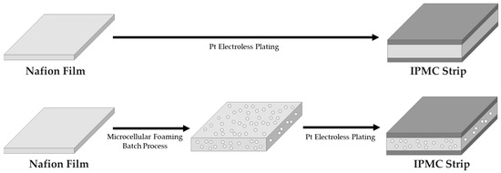
Figure 1.
Ionic polymer–metal composite (IPMC) strip prepared by microcellular foaming process of Nafion, which is the polymer electrolyte of this study.
2. Materials and Methods
2.1. Fabrication
In the batch process, MCP was performed on Nafion (type: film, product grade: NE-1110, density: 1.99 g/cm3, thickness: 200 µm, Dupont Co., Korea Branch, Seoul, Republic of Korea) (Figure 2 and Figure 3) as follows. Nafion specimen was placed in a high-pressure vessel, and CO2 (selected as the blowing agent) was injected through a completely sealed compressor. The CO2 penetrated the Nafion by diffusion until full saturation. This was achieved by setting the saturation pressure to 5 MPa and the saturation time to 24 h for all specimens in the experiment. The saturation temperatures were set to 20 and 40 °C, respectively, according to the experimental conditions listed in Table 1. After the saturation process, the Nafion specimen was taken out of the high-pressure vessel and thermodynamically destabilized by instigating rapid pressure drop and heat to induce a change in solubility, so that a cell could grow inside the Nafion as a substrate (Figure 4 and Figure 5). The foaming process temperature was set to 120 °C and 140 °C. Since the glass transition temperature of Nafion is 110 °C and its melting temperature is 160 °C, it was intended to select temperature points within that range. Moreover, glycerin was used as a medium for inducing the foaming, and the foaming time was 20 s, for all experimental conditions. Finally, Nafion films were foamed via each experiment, followed by the electrode layer, which was formed by reduction deposition of platinum by electroless plating [30].

Figure 2.
Nafion-based ionic polymer-metal composites: (A) structure of polymer electrolyte base layer and electrode; (B) scanning electron microscope image of a cross section.
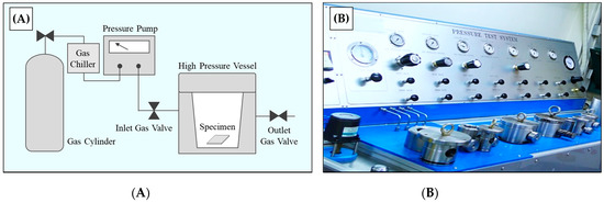
Figure 3.
(A) Schematic diagram of the microcellular foaming process in the batch process; (B) microcellular foam batch process equipment used in this study.

Table 1.
Experimental conditions of saturation and foaming process in microcellular foam batch process.
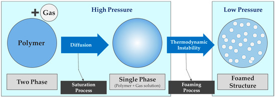
Figure 4.
Schematic diagram of theoretical principle of the microcellular foaming process.
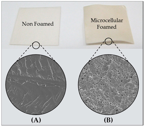
Figure 5.
Comparison of appearance and cross section of (A) non-foamed and (B) microcellular foamed Nafion specimens.
2.2. Measurements
2.2.1. Foaming Ratio
To derive the foaming ratio of the foamed Nafion, the density of the specimen (MD-300S, ALFA MIRAGE Co., Ltd., Osaka, Japan) was measured, and the foaming ratio was calculated using Equation (1), where d0 is the density of the non-foamed solid specimen, and d1 is the density of the microcellular foamed specimen.
2.2.2. Water Uptake Capability
The higher the water content of a polymer electrolyte membrane, the better the performance of the IPMC [31,32,33,34,35]. To obtain the water uptake capability value, the foamed Nafion film was vacuum dried, weighed, immersed in distilled water for 24 h, and then weighed again. The water uptake capability is calculated using Equation (2), where Mw is the weight of the Nafion film measured after dipping in distilled water for 24 h, and Md is the weight measured after vacuum drying the Nafion film.
2.2.3. Scanning Electron Microscopy
Cell morphology was determined by observing the cross section of specimens prepared according to the foaming conditions of the experiment using a field emission scanning electron microscope (FE-SEM-EDS, Product No. S-4700, HITACHI, Ltd., Tokyo, Japan). For IPMC, specimens coated with a Pt electrode layer on a Nafion film were observed; the cross section revealed a fracture formed by quenching, resulting in a notch on the specimen when subjected to liquid nitrogen.
2.2.4. Energy Harvesting Device
For our experiments, we designed and produced a device for investigating the energy harvesting properties of IPMC depending on the presence (or absence) of foamed cells (Figure 6). IPMC energy harvesting capabilities are generated by excitation when the voltage is applied to both electrodes, resulting in a driving displacement through the IPMC. An electric field is generated in the specimen by the applied voltage, and the water molecules located in the cations inside the Nafion film move toward the cathode. As the Nafion film contains water, one electrode expands and the other electrode expands and contracts consistently, causing a change in volume, resulting in a bending motion (Figure 7). Experiments were performed on each of the three non-foamed (NF) specimens, F1, F2, and F3 (each with different foaming ratios), for 30 min under the same conditions. During the experiments, a 20 s time period exhibiting the maximum value was selected, and the experiment was repeated 5 times to increase its reliability. The experiment was conducted under dry conditions without additional water supply during the experiment; the setup values of the harvesting device are listed in Table 2.
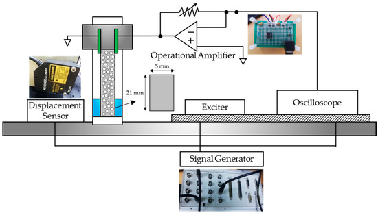
Figure 6.
Schematic diagram of the composition of harvester equipment.
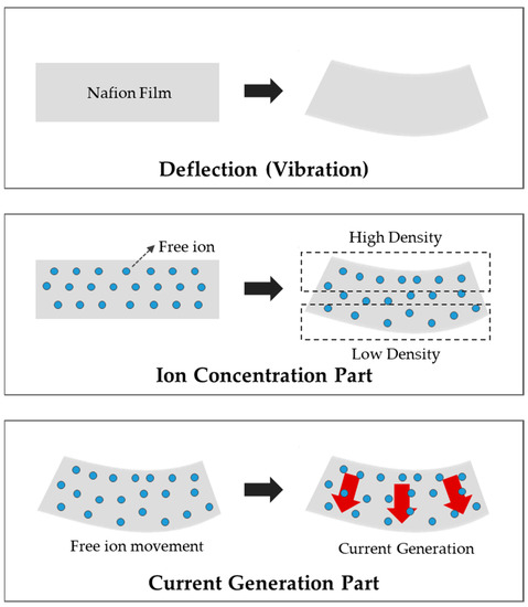
Figure 7.
Schematic diagram of working principle of the IPMC actuator.

Table 2.
Experimental conditions of lab-scale harvester prepared in this study.
The detailed experimental process is shown in Figure 6; the upper part of the IPMC specimen is fixed with the electrode, and the lower part is excited by changing the frequency to a predetermined signal using an exciter (Product No. Mini-shaker Type 4810, Brüel & Kjær Inc., Copenhagen, Denmark). The generated current value is increased using an operational amplifier (op-amp) to increase the harvest width. Moreover, the voltage drop was compensated by a power amplifier to provide a signal from the signal generator (Model No. DS1104 RTI, dSPACE Inc., Wixom, MI, USA) and obtain the desired type of movement. To simulate the uniform external force on each specimen, the experimental conditions were selected depending on the magnitude of the voltage applied to the exciter. The signal generator is a device that stores digital signals as analog signals or transforms analog signals into digital signals. A displacement sensor was installed to observe the actual movement during excitation, and its signal was received by an oscilloscope.
The exciter was excited by applying the signal listed in Table 2, and the electric charge was harvested using the signal. In this experiment, the current generated in the specimen was recorded. For this, an op-amp circuit including a variable resistor capable of recording the current in various bands was used. The incoming signal was converted to an enlarged voltage using an op-amp and received by an oscilloscope. Upon receiving the signal, the amount of current obtained from the specimen was set through a basic harvesting experiment that sets the size of the resistance for receiving the signal in a harvestable size.
2.2.5. Calibration
Since the enlarged current was harvested using the op-amp, it is necessary to verify that the calculated amount of current was obtained correctly after passing through the circuit. As there is a limit to the strength of the signal that can be recognized by the oscilloscope, a method of harvesting the specimen current by calculating the signal inversely by sending it through a specific current and then accepting it through the op-amp was used. After confirming that the current was obtained at the level of 0.1 µA, it was magnified by approximately 107 times to obtain it at the level compatible with the oscilloscope. Then, the signal was sent through a 1-V signal exciter, dropped to a desired level of current using a 10 MΩ resistor, and then received again to confirm that the op-amp was working properly. However, in the case of specimens corresponding to the specific experimental conditions, the experiment was conducted by lowering the magnification of the current to 106 times, as values exceeding the range were harvested.
3. Results and Discussion
3.1. Cell Morphology of Microcellular Foamed IPMC according to Foaming Ratio
Each specimen showed a difference in foaming properties according to the experimental conditions (Table 3). In the case of NF, under the test conditions highlighted, it was observed that the cross section of the Nafion specimen is constant, and it hardly changed from that before applying the foam to that after plating Pt by electroless plating (Figure 8). Under its specific experimental conditions, F1 reported a saturation temperature of 40 °C. F1 also showed a relatively low solubility than that of 20 °C, and a few cells were visually confirmed to have formed at the calculated foaming ratio (Figure 9). However, when examining changes in thickness and changes in water content, cell nucleation occurred inside, but since the foaming temperature was relatively low, sufficient thermodynamic instability was not achieved. As such, the degree of growth of cells was small, as observed clearly for F2, which has the same saturation conditions as F1 but different the foaming temperature. CO2, (the blowing agent) penetrated the interior of the polymer through diffusion and existed as a nucleus, and it grew owing to the thermodynamic instability of F2. For F2, voids not seen in F1 existed. Under its specific experimental conditions, F2 had a lower density of approximately 1.84 g/cm3, and its foaming ratio was also approximately 8.2% (Figure 10). The cell size of F2 was estimated to be 5 microns, and since its saturation temperature was relatively high, it was concluded that its cell density was low, owing to low solubility. In addition, it was confirmed that approximately four to five cells were formed on average in every 20 µm, lengthwise. Under its specific experimental conditions, F3 had a cell size of approximately 1 µm; it was denser with an average of approximately 15 cells formed every 20 µm in the longitudinal direction (Figure 11). Its foaming ratio was approximately 16.4%, and its cell size was smaller than that of F2. It was concluded that the blowing agent CO2 formed a relatively large number of nuclei as its solubility in F3 was higher than that in F2.

Table 3.
Density, foaming ratio, and thickness of specimens, according to foaming conditions of Nafion.
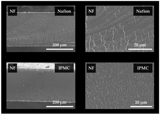
Figure 8.
Scanning electron microscope observation images of cross sections of non-foamed Nafion and IPMC specimens.
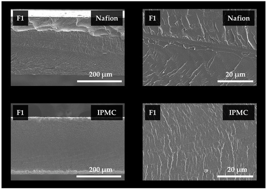
Figure 9.
Scanning electron microscope observation image of the cross section of Nafion and IPMC specimens, according to the F1 foaming condition.
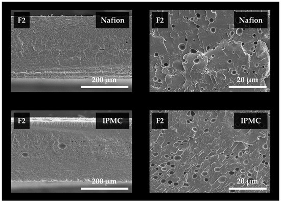
Figure 10.
Scanning electron microscope observation image of the cross section of Nafion and IPMC specimens, according to the F2 foaming condition.
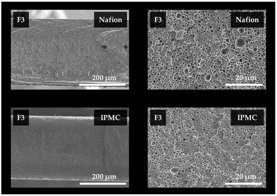
Figure 11.
Scanning electron microscope observation image of the cross section of Nafion and IPMC specimens, according to the F3 foaming condition.
3.2. Electrical Characteristics of Microcellular Foamed IPMC
The energy harvesting experiment was conducted at a frequency of 20 Hz or less. In the case of a microcellular foamed specimen, when vibrations of a specific frequency range were applied, a significant amount of energy was harvested from foamed specimens, when compared to non-foamed specimens (Figure 12). The resulting value was converted by calculating the correction value obtained through calibration for the harvested current. In the frequency band, the resulting value was converted to the root mean square (RMS) value, and a 20 s time period (from a total of approximately 30 min) that exhibited the highest value was selected and plotted. Two specimens were subjected to the same experimental conditions, and the average value was adopted. For each experimental condition, we plotted a graph of output current against time (Figure 13 and Figure 14). It was observed that foamed specimens recorded a higher frequency band with the highest value (Figure 12). However, in the low-frequency band, as shown in Figure 15A, it can be seen that the non-foamed specimens have higher energy yield than the foamed specimens. This can be attributed to the more acute movements in non-foamed specimens. In the frequency band around 10 Hz, it was observed that the foamed specimen moved much more rapidly than the non-foamed specimen, as shown in Figure 15B, and the resulting value differed by up to approximately three times.
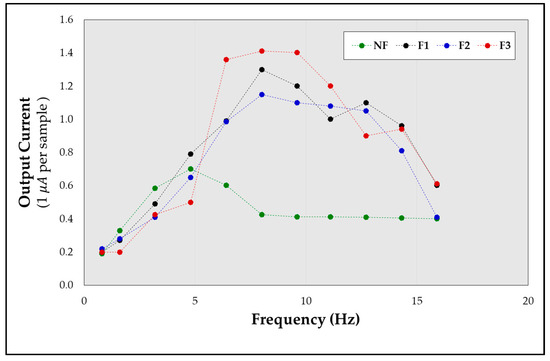
Figure 12.
Output current corresponding to frequency variations of IPMC specimens, prepared according to the foaming conditions for Nafion.
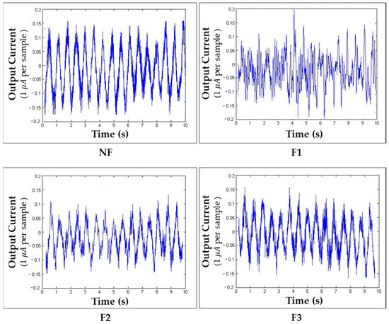
Figure 13.
Output current corresponding to time according to the foaming conditions of IPMC: 1.6 Hz, 1 V.
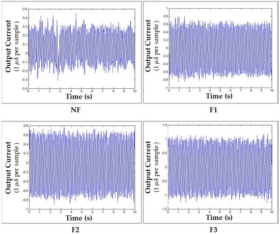
Figure 14.
Output current corresponding to time according to the foaming conditions of IPMC: 8 Hz, 1 V.
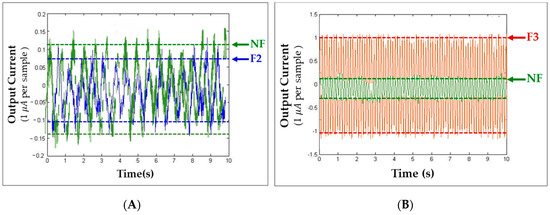
Figure 15.
Comparison of output current corresponding to time: (A) NF and F2 (1.6 Hz, 1 V); (B) NF and F3 (8 Hz, 1 V).
Capacitance was measured with a resonance of 0.001 µF in the 120 Hz region after vacuum drying the specimen under each condition. Different values were obtained for each sample. As the foaming ratio increased, the water retention capacity was increased by the cells present therein, and the capacitance was also improved (Table 4). It is assumed that the increase in the thickness of the polymer electrolyte membrane and increase in water retention improve the operational performance of the capacitance, because the water content in the IPMC acts as a factor affecting relaxation and has a major effect on the capacitance.

Table 4.
Water content and capacitance of IPMC specimens according to the foaming conditions for Nafion.
4. Conclusions
In this study, we imparted porosity to a polymer electrolyte membrane by MCP of Nafion to improve its electrical harvesting performance, especially when compared with conventional IPMC. We observed that a cell, several microns in size, was formed in the base layer Nafion film. As the thickness of the Nafion film increased, the electrical harvesting performance of the IPMC improved, owing to the retention of more water in its internal pores (Figure 16). Therefore, it was possible to improve the electrical harvesting performance, as well as the operational stability of the IPMC. This was because a fundamental change in morphology is caused by the cells generated in the base layer of the Nafion film, and the operational stability of the IPMC is ensured even with changes in the external environment. In addition, the change in the internal morphology of electrolyte membrane (due to an increase in the foaming ratio when implementing the MCP) is considered to improve the harvesting performance of the IPMC; this improvement is attributed to an increase in the amount of electric charge in the impregnated electrolyte, and changes in electrical properties (such as capacitance), as well as an increase in the water content. The enhancement in the harvesting characteristics observed in the band above a specific frequency can be ascribed to the improved electrical characteristics of the foamed IPMC and the increase in feedback, according to the input movement of the ions according to the frequency band, due to the internal morphology change (Figure 17). Previous studies have attempted to improve the IPMC performance by changing the materials (and their quantities) involved; in addition to pure metals (such as platinum, copper, and gold), alloys such as platinum/palladium or carbon nanotube-based composite materials have been used. However, the present study was conducted with a focus on the possibility of improving the harvesting performance of the IPMC through a fundamental change only in the morphology of the polymer electrolyte membrane.
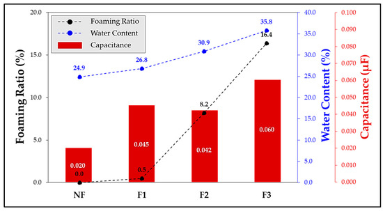
Figure 16.
Water content and capacitance corresponding to the foaming ratio of IPMC specimen prepared according to the foaming conditions of Nafion.
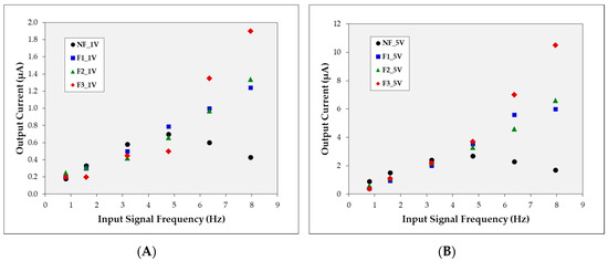
Figure 17.
Output current corresponding to input signal frequency when input signal voltage is (A) 1 V, (B) 5 V.
Author Contributions
Conceptualization, B.C.K.; investigation, B.C.K.; methodology, B.C.K., and J.S.S.; data curation, J.S.S. and Y.R.; writing—original draft preparation, B.C.K. and J.S.S.; writing—review and editing, J.S.S.; visualization, J.S.S.; supervision, S.W.C.; project administration, S.W.C.; funding acquisition, S.W.C. All authors have read and agreed to the published version of the manuscript.
Funding
This research was supported by Basic Science Research Program through the National Research Foundation of Korea (NRF) funded by the Ministry of Education (No. NRF-2018R1D1A1B07049405).
Acknowledgments
The authors would like to thank the editors and anonymous reviewers for their useful comments and feedback.
Conflicts of Interest
The authors declare no conflict of interest.
References
- Jang, L.; Kuo, K. Fabrication and Characterization of PZT Thick Films for Sensing and Actuation. Sensors 2007, 7, 493–507. [Google Scholar] [CrossRef]
- Sodano, H.; Inman, D.; Park, G. Comparison of Piezoelectric Energy Harvesting Devices for Recharging Batteries. J. Intell. Mater. Syst. Struct. 2005, 16, 799–807. [Google Scholar] [CrossRef]
- Shahinpoor, M.; Bar-Cohen, Y.; Simpson, J.O.; Smith, J. Ionic polymer-metal composites (IPMCs) as biomimetic sensors, actuators and artificial muscles—A review. Smart Mater. Struct. 1998, 7, R15–R30. [Google Scholar] [CrossRef]
- Shahinpoor, M.; Kim, K. Ionic polymer-metal composites: I. Fundamentals. Smart Mater. Struct. 2001, 10, 819–833. [Google Scholar] [CrossRef]
- Kim, K.; Shahinpoor, M. Ionic polymer metal composites: II. Manufacturing techniques. Smart Mater. Struct. 2003, 12, 65–79. [Google Scholar] [CrossRef]
- Kim, S.J.; Kim, M.S.; Shin, S.R.; Kim, I.Y.; Kim, S.I.; Lee, S.H.; Lee, T.S.; Spinks, G.M. Enhancement of the electromechanical behavior of IPMCs based on chitosan/polyaniline ion exchange membranes fabricated by freeze-drying. Smart Mater. Struct. 2005, 14, 889–894. [Google Scholar] [CrossRef]
- Lee, H.; Choi, N.; Jung, S.; Park, K.; Jung, H.; Shim, J.; Ryu, J.; Kim, J. Electroactive Polymer Actuator for Lens-Drive Unit in Auto-Focus Compact Camera Module. ETRI J. 2009, 31, 695–702. [Google Scholar] [CrossRef]
- Tan, X. Autonomous Robotic Fish as Mobile Sensor Platforms: Challenges and Potential Solutions. Mar. Technol. Soc. J. 2011, 45, 31–40. [Google Scholar] [CrossRef]
- Abdulrab, H.; Mohd Nordin, I.; Muhammad Razif, M.; Mohd Faudzi, A. Snake-like Soft Robot Using 2-Chambers Actuator. ELEKTRIKA-J. Electr. Eng. 2018, 17, 34–40. [Google Scholar] [CrossRef]
- Nemoto, Y.; Aoki, S.; Kamamichi, N. Wireless control snake-like underwater propulsion robot using ionic polymer-metal composite actuator. Proc. JSME Annu. Conf. Robot. Mechatron. (Robomec) 2018, 2018, 2P1–H12. [Google Scholar] [CrossRef]
- Kamamichi, N.; Yamakita, M.; Asaka, K.; Mukai, T. 1P1-G01 A Snake-like Swimming Robot with IPMC Actuator/Sensor: Propulsive Property and Experiment of Autonomous Locomotion. Proc. JSME Annu. Conf. Robot. Mechatron. (Robomec) 2007, 2007, _1P1-G01_1–_1P1-G01_4. [Google Scholar]
- Zhu, Z.; Chen, H.; Li, B.; Wang, Y. Characteristics and Elastic Modulus Evaluation of Pd-Nafion Ionic Polymer-Metal Composites. Adv. Mater. Res. 2010, 97–101, 1590–1594. [Google Scholar] [CrossRef]
- Bennett, M.; Leo, D. Ionic liquids as stable solvents for ionic polymer transducers. Sens. Actuator A Phys. 2004, 115, 79–90. [Google Scholar] [CrossRef]
- Akle, B.; Leo, D. Characterization and modeling of extensional and bending actuation in ionomeric polymer transducers. Smart Mater. Struct. 2007, 16, 1348–1360. [Google Scholar] [CrossRef]
- Chen, Z.; Hedgepeth, D.; Tan, X. A nonlinear, control-oriented model for ionic polymer–metal composite actuators. Smart Mater. Struct. 2009, 18, 055008. [Google Scholar] [CrossRef]
- Lee, S.; Han, M.; Kim, S.; Jho, J.; Lee, H.; Kim, Y. A new fabrication method for IPMC actuators and application to artificial fingers. Smart Mater. Struct. 2006, 15, 1217–1224. [Google Scholar] [CrossRef]
- Jo, C.; Pugal, D.; Oh, I.K.; Kim, K.J.; Asaka, K. Recent advances in ionic polymer-metal composite actuators and their modeling and applications. Prog. Polym. Sci. 2013, 38, 1037–1066. [Google Scholar] [CrossRef]
- Palmre, V.; Brandell, D.; Maeorg, U.; Torop, J.; Volobujeva, O.; Punning, A.; Johanson, U.; Kruusmaa, M.; Aabloo, A. Nanoporous carbon-based electrodes for high strain ionomeric bending actuators. Smart Mater. Struct. 2009, 18, 095028. [Google Scholar] [CrossRef]
- Guo, D.J.; Fu, S.J.; Tan, W.; Dai, Z.D. A highly porous Nafion membrane templated from polyoxometalates-based supramolecule composite for ion-exchange polymer-metal composite actuator. J. Mater. Chem. 2010, 20, 10159–10168. [Google Scholar] [CrossRef]
- Vunder, V.; Itik, M.; Poldsalu, I.; Punning, A.; Aabloo, A. Inversion-based control of ionic polymer-metal composite actuators with nanoporous carbon-based electrodes. Smart Mater. Struct. 2014, 23, 025010. [Google Scholar] [CrossRef]
- Jung, S.Y.; Ko, S.Y.; Park, J.O.; Park, S. Enhanced ionic polymer metal composite actuator with porous Nafion membrane using zinc oxide particulate leaching method. Smart Mater. Struct. 2015, 24, 037007. [Google Scholar] [CrossRef]
- Zhao, D.; Li, D.; Wang, Y.; Chen, H. Improved manufacturing technology for producing porous Nafion for high-performance ionic polymer-metal composite actuators. Smart Mater. Struct. 2016, 25, 075043. [Google Scholar] [CrossRef]
- He, Q.; Liu, Z.; Yin, G.; Yue, Y.; Yu, M.; Li, H.; Ji, K.; Xu, X.; Dai, Z.; Chen, M. The highly stable air-operating ionic polymer metal composite actuator with consecutive channels and its potential application in soft gripper. Smart Mater. Struct. 2020, 29, 045013. [Google Scholar] [CrossRef]
- Li, Y.; Zhou, X.; Qi, W.; Xie, H.; Yin, K.; Tong, Y.; He, J.; Gong, S.; Li, Z. Ultrafast fabrication of Cu oxide micro/nano-structures via laser ablation to promote oxygen evolution reaction. Chem. Eng. J. 2020, 383, 123086. [Google Scholar] [CrossRef]
- Leichsenring, P.; Serdas, S.; Wallmersperger, T.; Bluhm, J.; Schröder, J. Electro-chemical aspects of IPMCs within the framework of the theory of porous media. Smart Mater. Struct. 2017, 26, 045004. [Google Scholar] [CrossRef]
- Cha, S.W. A Microcellular Foaming/Forming Process Performed at Ambient Temperature and a Super Microcellular Foaming Process. Ph.D. Thesis, Massachusetts Institute of Technology, Cambridge, MA, USA, 1994. [Google Scholar]
- Cha, S.W.; Suh, N.P.; Baldwin, D.F.; Park, C.B. Microcellular Thermoplastic Foamed with Supercritical Fluid. U.S. Patent 5,158,986, 27 October 1992. [Google Scholar]
- Colton, J.; Suh, N. The nucleation of microcellular thermoplastic foam with additives: Part I: Theoretical considerations. Polym. Eng. Sci. 1987, 27, 485–492. [Google Scholar] [CrossRef]
- Colton, J.; Suh, N. The nucleation of microcellular thermoplastic foam with additives: Part II: Experimental results and discussion. Polym. Eng. Sci. 1987, 27, 493–499. [Google Scholar] [CrossRef]
- Oguro, K.; Ion-Exchange Polymer Metal Composites (IPMC) Membranes. Preparation Procedure. Available online: http://ndeaa.jpl.nasa.gov/nasa-nde/lommas/eap/IPMC_PrepProcedure.htm (accessed on 17 June 2020).
- Li, S.; Yip, J. Characterization and Actuation of Ionic Polymer Metal Composites with Various Thicknesses and Lengths. Polymers 2019, 11, 91. [Google Scholar] [CrossRef]
- Zhao, Y.; Sheng, J.; Xu, D.; Gao, M.; Meng, Q.; Wu, D.; Wang, L.; Lv, W.; Chen, Q.; Xiao, J.; et al. Improve the Performance of Mechanoelectrical Transduction of Ionic Polymer-Metal Composites Based on Ordered Nafion Nanofibres by Electrospinning. Polymers 2018, 10, 803. [Google Scholar] [CrossRef]
- Giacomello, A.; Porfiri, M. Underwater energy harvesting from a heavy flag hosting ionic polymer metal composites. J. Appl. Phys. 2011, 109, 40–202. [Google Scholar] [CrossRef]
- Cha, Y.; Abdolhamidi, S.; Porfiri, M. Energy harvesting from underwater vibration of an annular ionic polymer metal composite. Meccanica 2015, 50, 2675–2690. [Google Scholar] [CrossRef]
- Ru, J.; Wang, Y.; Chang, L.; Chen, H.; Li, D. Preparation and characterization of water-soluble carbon nanotube reinforced Nafion mats and so-based ionic polymer metal composite actuators. Smart Mater. Struct. 2016, 25, 095006. [Google Scholar] [CrossRef]
© 2020 by the authors. Licensee MDPI, Basel, Switzerland. This article is an open access article distributed under the terms and conditions of the Creative Commons Attribution (CC BY) license (http://creativecommons.org/licenses/by/4.0/).